How to Fix iPhone XS Unresponsive Touch Screen
Prior to commencing any repair work, confirm the device is completely disconnected from all electrical power.
- The following implements are necessary for this procedure:A Phillips-head screwdriver is needed., A soldering iron will also be required.
Caution:Careless operation of the soldering iron presents a risk of thermal injury; consistently maintain vigilance while utilizing it.
Step 1 | Screen


Initiating the repair process with step one.Begin by inspecting the motherboard meticulously; confirm its physical integrity, verifying the absence of any warping or signs of water exposure.
- Proceed with mounting the motherboard for a preliminary test; establish a display connection and attach the battery, then power on the device. The touchscreen functionality is currently unresponsive.
- Subsequently, evaluate the touch connector's electrical characteristics; a measurement reveals an open circuit on pin 21, signifying a malfunction within the circuit associated with that pin.
Step 2


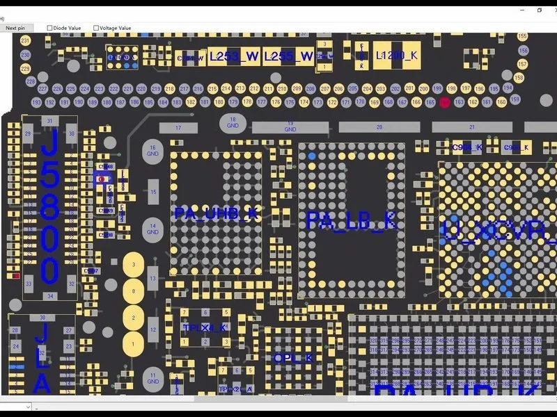
Proceed to step 2.Access the bitmap; observe that pin 21 is linked to resistor R5842. This safety resistor has both terminals joined together.
- It is essential to evaluate the resistor's condition through measurement to determine if it has failed.
- Utilize a multimeter to perform the measurement; since the resistor exhibits a functional state, we can conclude that the resistor is not the source of the problem, indicating a potential fault within the circuit located on the internal layer.
Step 3


Procedure 3:Following this, detach the motherboard and position it on a 160 °C heating platform for approximately one minute of exposure to heat.
- Utilizing tweezers, carefully extract the logic board and signal board, noting the prior separation of the motherboard.
- Consequently, it is essential to initially assess the electrical circuit on the logic board, verifying that the resistance value is within the expected range.
Step 4


Proceed to step four.An interruption exists within the electrical pathway; restore continuity by creating a direct connection with a wire.
- To facilitate soldering, apply a flux agent to the resistor's surface. Utilize a soldering iron, heated to 360 degrees Celsius, to securely attach the copper wire to the resistor.
- Subsequently, apply a protective coating of solder mask to the remaining copper wire.
- Apply a layer of solder mask to protect the signal board's pads, allowing them to harden; then, carefully remove the excess material to expose the pads, and finally, cleanse the bonding pads with a specialized PCB cleaning solution.
Step 5


Procedure 5:Reattach the signal board to the logic board, ensuring precise alignment.
Reinstall the motherboard and perform a functional test to confirm proper touch screen operation.
- Position the signal board onto the160 °C Heating Platformfor thermal processing.
- Apply a thin layer of Paste Flux to the bonding area.
- Secure the logic board in its correct location and use tweezers to apply light pressure while the heating process continues; after approximately one minute, remove the motherboard from the platform.
Reinstall the motherboard and perform a functional test to confirm proper touch screen operation.