Repair tricks for desoldering & soldering of iPhone X charging IC
Prior to commencing any repair work, it is essential to disconnect the device entirely from all electrical power supplies.
- Necessary Tools:A Phillips head screwdriver is needed for this procedure.
Should difficulties arise while performing the repair, refer to the manufacturer's provided instructions or obtain help from a qualified technician.
Step 1 | Repair tricks for desoldering&soldering of iPhone X charging IC
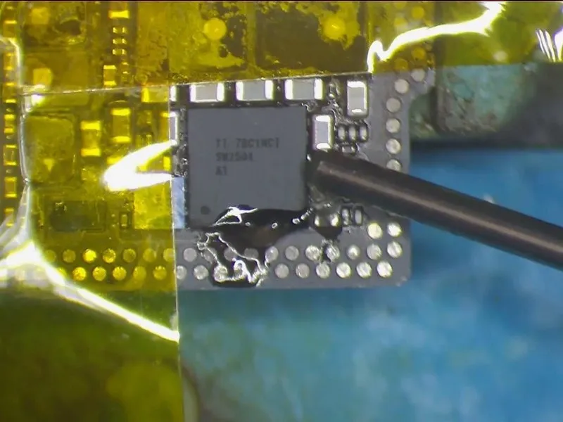

- Initially, affix high-temperature tape to the surrounding components to shield them from unintended solder bridges or shorts while working near the charging IC.
- Subsequently, distribute a thin layer of flux paste around the charging IC.
- Configure the QUICK 990 AD Vertical Wind Hot Air Gun's temperature to 330°C, maintaining an airflow rate of 3. Position the hot air gun between 5 millimeters and 10 millimeters above the charging IC and apply heat for approximately 15 to 20 seconds before attempting to lift the IC.
- Exercise careful control over the force used when separating the IC from the board, as excessive force could potentially harm the chip or its connecting pads.
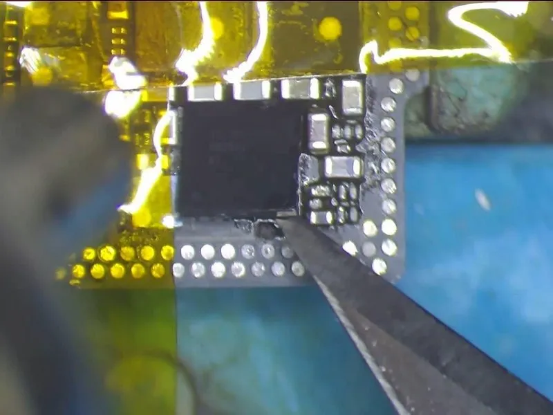
Step 2

- Proceed with the application of medium-temperature solder paste onto the bonding pad. Subsequently, utilize theQUICK 990 AD Vertical Wind Hot Air Gun employing a temperature of 280°C and an airflow rate of 3.
- Concurrently, remove excess solder from the bonding pad's joints using aSoldering Iron set to 360°C. Following this, meticulously cleanse the pad by utilizing solder wick saturated with rosin.
- Exercise caution during this procedure, as forceful actions could potentially lead to unintended solder bridges or short circuits between nearby components.
Complete the cleaning process by applying PCB Cleaner afterward.
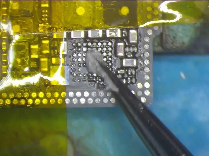
Step 3


- It is now necessary to remove any residue from the solder connections located on the reverse side of the charging IC; to facilitate this, apply a moderate temperature solder paste to the bonding area on that rear surface.
- Utilize a Soldering Ironset to a temperature of 360°C
- Furthermore, the application of a paste flux can improve the cleaning process; after the cleaning is complete, use PCB Cleaner.
Exercise caution and avoid overly aggressive cleaning of the solder joints on the pad, as retaining a few connections is advisable to ensure successful reballing in a subsequent step.
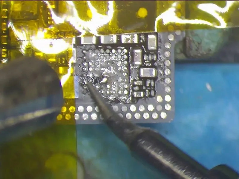
Step 4
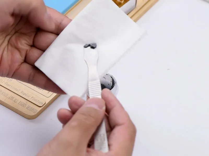
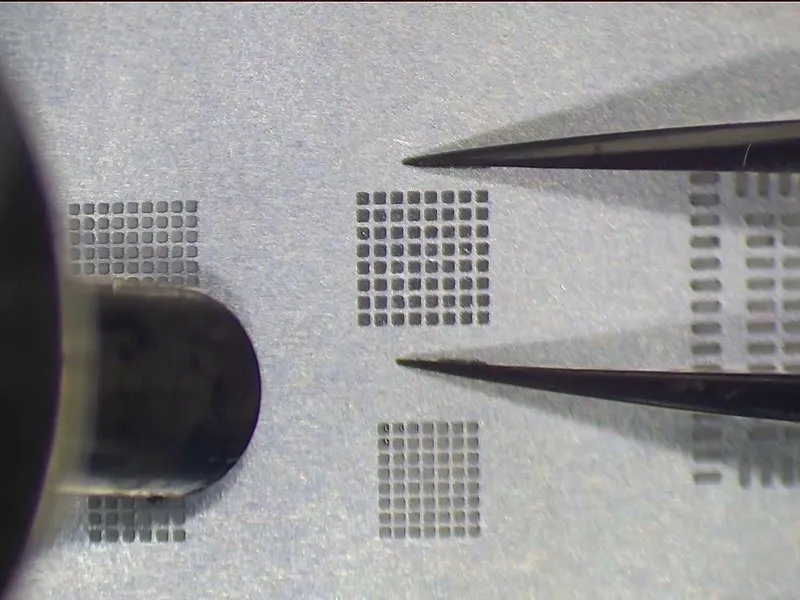
- Now, we will proceed with the reballing procedure; ensure theBGA Reballing Stencilis correctly aligned. Utilize medium-temperature solder paste and aBGA Scraper.
Step 5

- Excessive heat exposure carries the risk of stencil distortion, and may also compromise the precise formation of solder spheres.
- Allow a cooling period of 60 seconds before utilizing PCB Cleaner for cleaning.
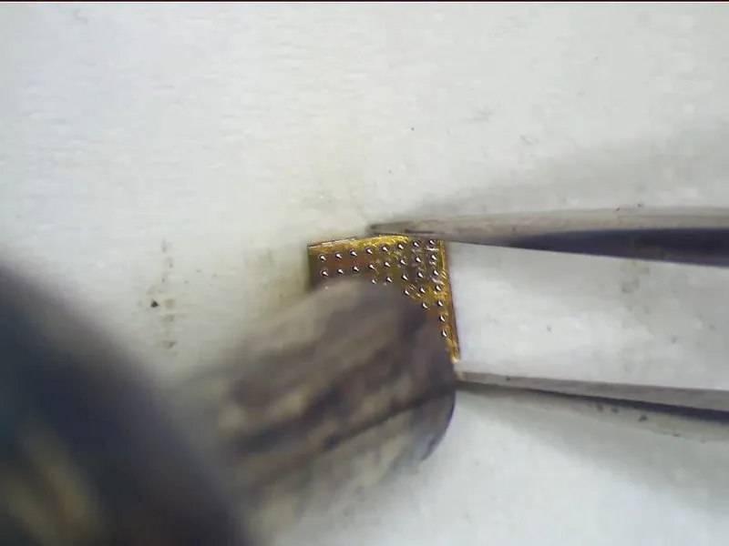
- Carefully detach the chip from the stencil using tweezers, and subsequently secure the chip with tweezers.
- Reapply heat utilizing theQUICK 990 AD Vertical Wind Hot Air Gunat a temperature of 300°C, employing an airflow rate of 3, to guarantee the ideal solder ball morphology.
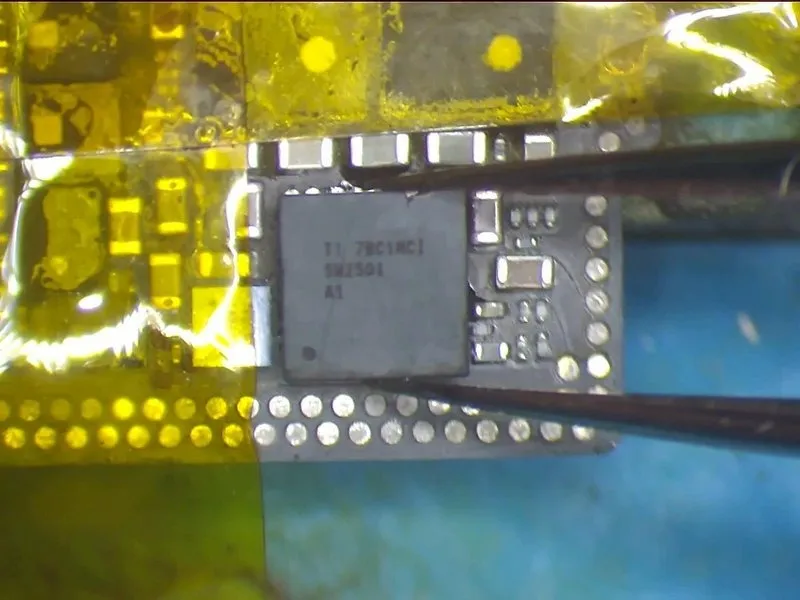
- Proceed with the soldering of the charging IC, beginning with the application of a flux paste to the bonding pad.
- Position the charging IC accurately, ensuring correct orientation to prevent improper placement.
- Employ theQUICK 990 AD Vertical Wind Hot Air Gunat a temperature of 330°C, with an airflow rate of 2, for a duration of 15 to 20 seconds, allowing the IC to settle and the flux paste to overflow.