iPhone X Says No Service? Here's the fix!
Prior to commencing any repair work, disconnect the device completely from all electrical power.
- To complete this repair, you will need the following tools:Use a Phillips head screwdriver.
Consult the user manual to find model-specific information and supplementary safety guidelines.
Step 1 | No Service
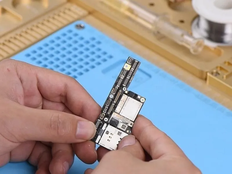
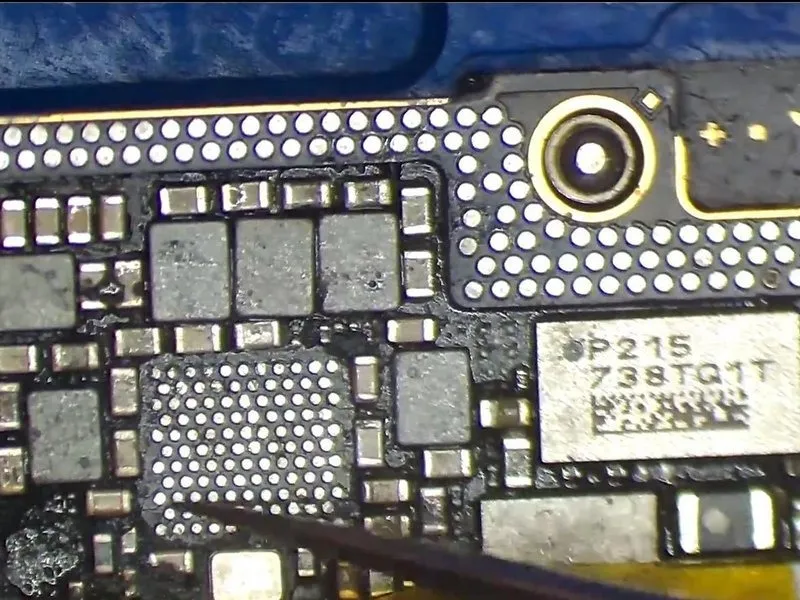
- Carefully examine the motherboard's exterior for any visible damage.Carefully handle the printed circuit board, ensuring no static discharge occurs, and noting its dimensions of 12 x 9.5 inches, while recognizing it contains delicate electronic components and requires the use of a #2 Phillips screwdriver for securing connectors, with a warning to avoid applying excessive torque (no more than 5 in-lbs) to prevent damage.Ensure the component exhibits no warping and shows no signs of water exposure.
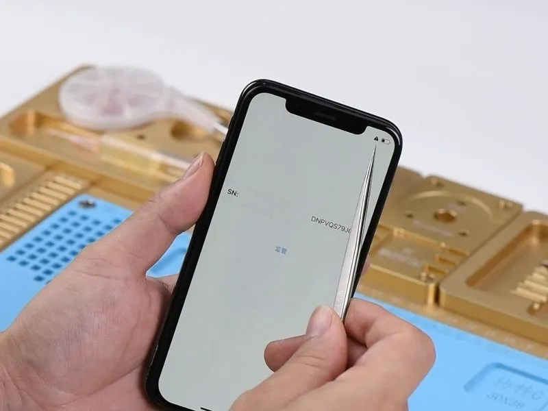
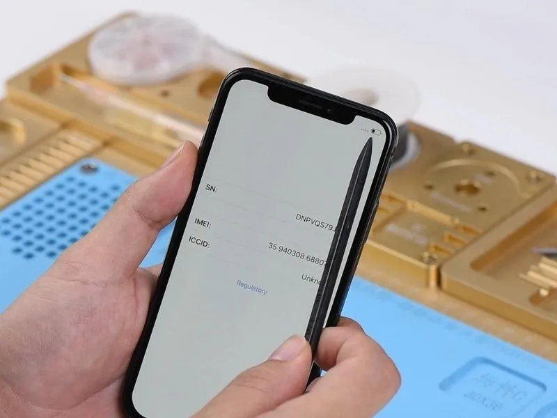
- Proceed with the installation of theCarefully handle the printed circuit board, ensuring no static discharge occurs, and noting its dimensions of 12 x 9.5 inches, as damage can result from improper handling.Following connection of the battery and display assembly, power on the device and allow it to complete its activation sequence. Then, select the icon located in the lower-right corner of the screen; a standard serial number display should appear.Locate the device's unique 15-digit identifier, designated as IMEI.Observe the displayed numerical value on the device's screen.The device is not currently connected to a service provider.A fault indication will appear in the display's top-right area.
- Given this observation, a false solder joint on the bonding pad or a failure within the lower layer is probable; proceed to detach theCarefully handle the printed circuit board, ensuring no static discharge occurs, and noting its dimensions of 12 x 9.5 inches, as damage can result from improper handling..
Step 2
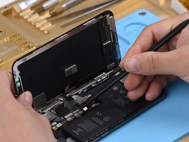
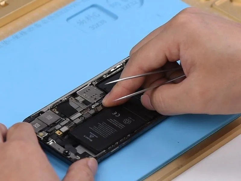
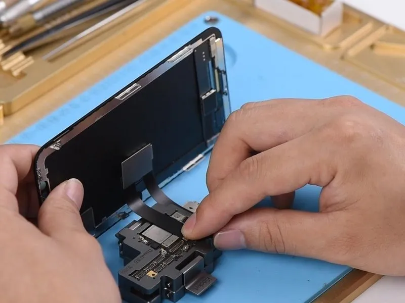
- Begin by detaching the display assembly, then sever the battery connection, and subsequently extract theCarefully handle the printed circuit board, ensuring no static discharge occurs, and noting its dimensions of 12 x 9.5 inches, as damage can result from improper handling..
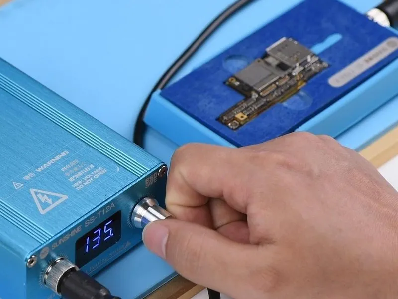
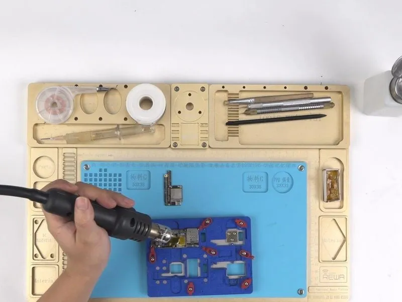
- Position theCarefully handle the printed circuit board, ensuring no static discharge occurs, and noting its dimensions are 12 inches by 9 inches, as damage to its components, including the CPU socket and RAM slots, can result in irreversible failure.Activate the heating platform, ensuring it's positioned correctly, and adjust the temperature setting to precisely 150°C.
Step 3
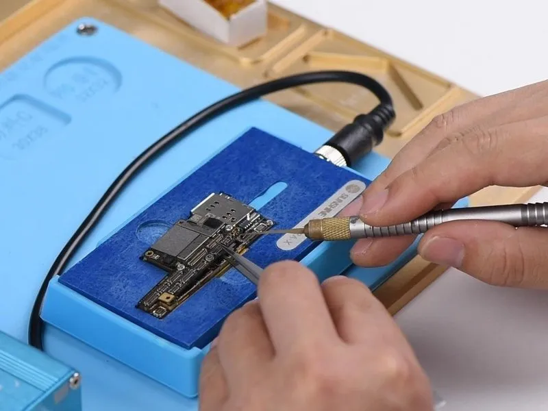
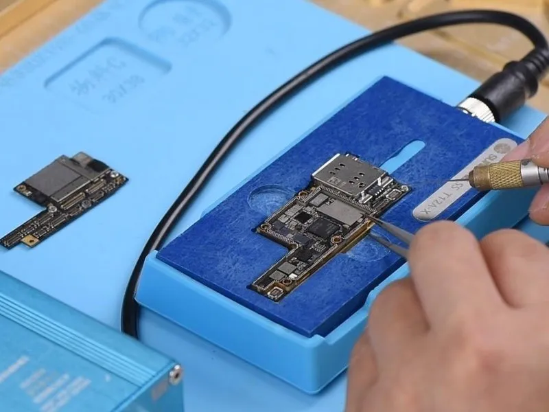
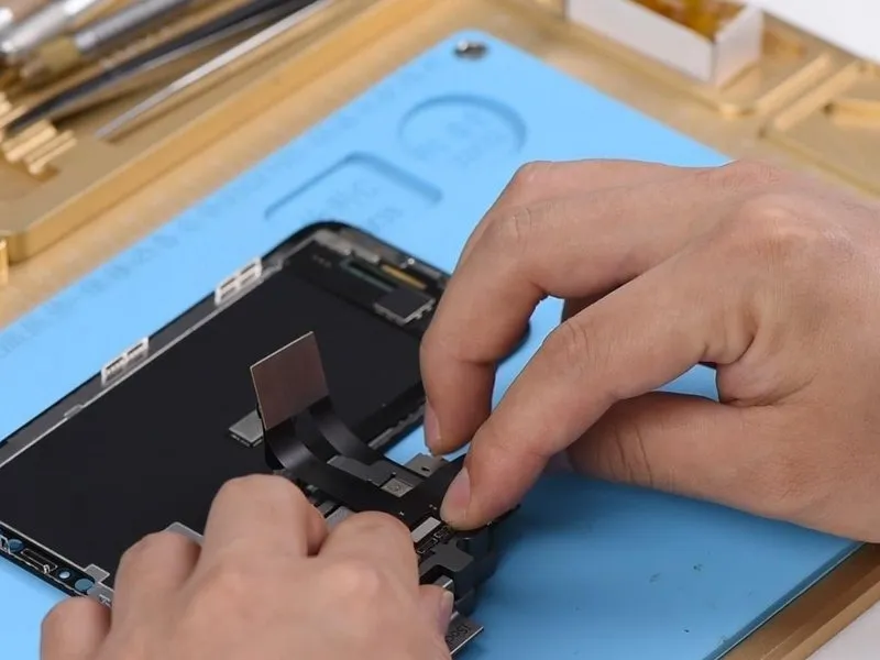
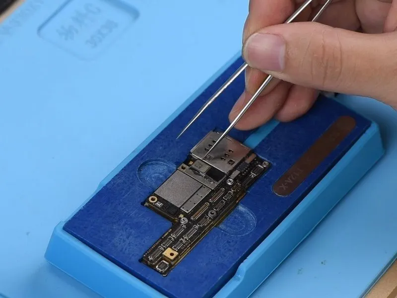
- Carefully lift the upper layer using tweezers once the platform temperature reaches 150°C.
- Detach the lower platform assembly and subsequently deactivate the heating element.
Step 4
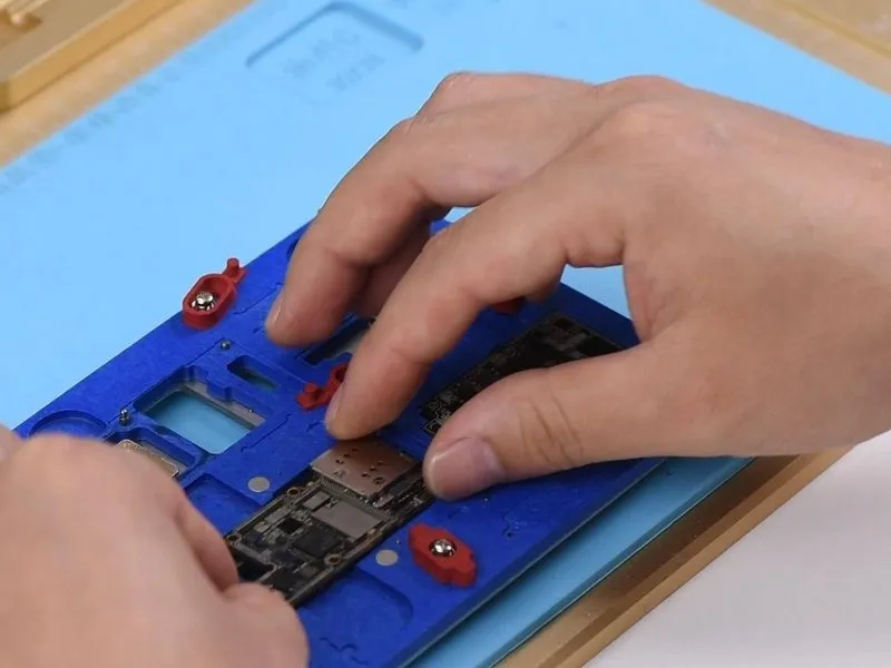

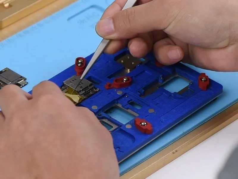
- Secure both the upper and lower PCB layers to the PCB Holder.
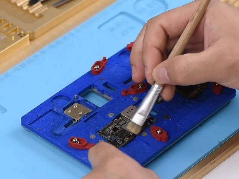
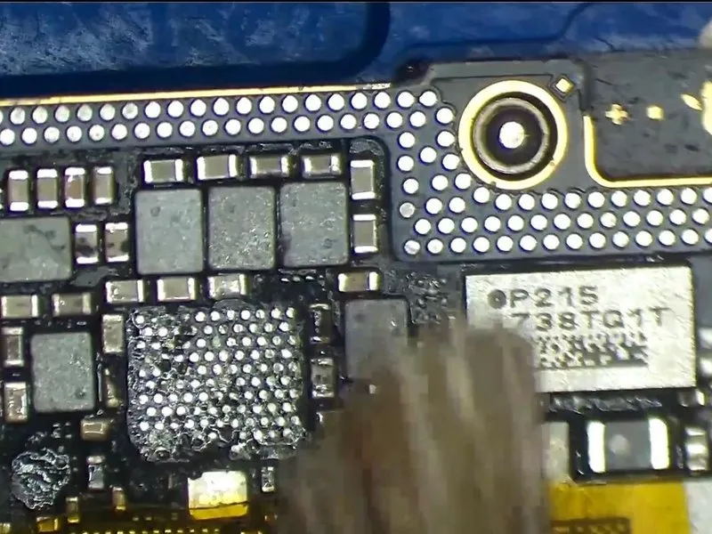
- Using a soldering iron set to 360°C, employ rosin-soaked solder wick to remove any oxidation or debris from the pads located along the upper layer's edges and the bonding pad.
- Following the procedure, use PCB Cleaner to remove any residue.
Step 5

- Carefully separate theThe component situated above all others.Using the 5/32-inch hex key, carefully tighten the retaining screw to a torque of 4.5 Nm, ensuring no damage occurs to the threaded hole.The component situated beneath other elements.Securely fasten to the printed circuit board mounting bracket.The component situated above all others.Using a 5/32-inch hex key, carefully tighten the retaining screw to a torque of 3.2 Nm, ensuring the spindle lock remains engaged and preventing over-tightening which could damage the bearing.The component situated beneath other elements.Secure the component to the designated testing apparatus.
- Establish a connection between the display assembly and the power supply by joining the battery connector. Initiate the system's power detection sequence by depressing the power button located on the Power Supplier.
Step 6

- During activation, a screen icon located in the lower-right corner should be selected, confirming the serial number's proper display; however, the absence of an IMEI number is observed on the device's screen.The device is currently unable to connect to network services.A fault indicator will appear in the upper-right corner.
- Verification indicates the bonding pad lacks a false solder connection; the issue originates fromThe component situated beneath other elements.It's necessary to perform an additional inspection.The component situated beneath other elements..
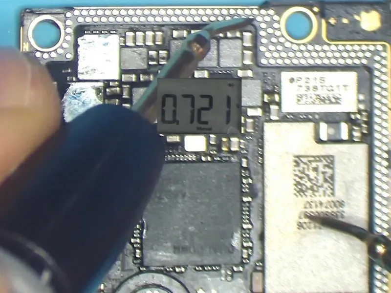
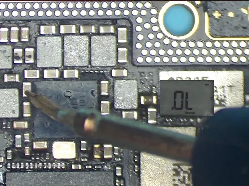
- Using diode mode, measure the voltage across the signal pins on the bonding pad; a successful test will show no errors.
- Verify the functionality of capacitors within the U_PMIC_E power supply circuit by performing ongoing diode mode measurements, ensuring no errors are detected.
- Based on these observations, the issue likely stems fromRefer to U_PMIC_E.orUsing a 5mm hex key, carefully loosen the U_MDM_E screw, ensuring to observe the specified torque of 0.8 Nm, and be aware that overtightening could damage the threads..
Step 7
- Initiate a substitution process using a fresh component.Refer to the U_PMIC_E component.Observe the functionality by initially applying High-temperature Tape toUsing a 5mm hex key, carefully loosen the U_MDM_E screw, ensuring to observe the specified torque of 0.5 Nm, and be aware that overtightening could damage the threads.Carefully handle the WiFi module.
- Detach the component.Refer to the U_PMIC_E component.Apply heat using a hot air gun set to 330°C, ensuring an airflow rate of 3.
Step 8


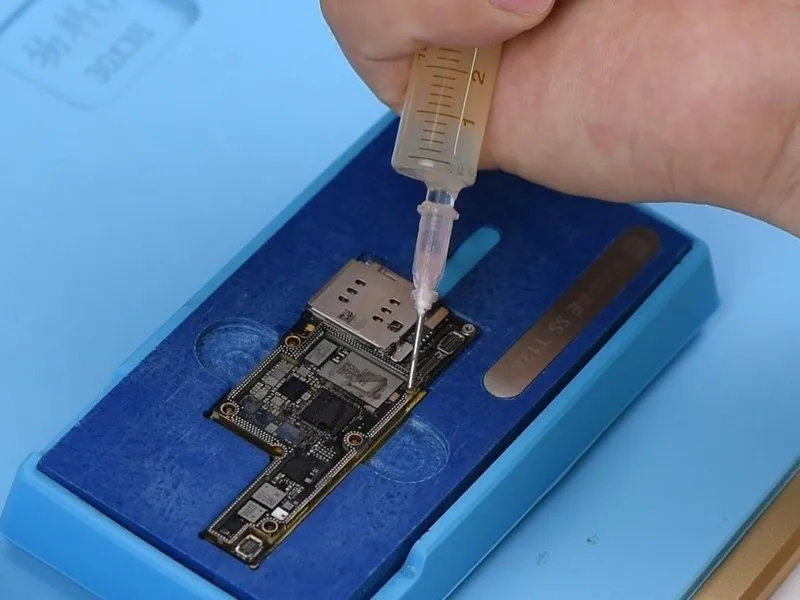
- Ensure the bonding pad remains coated with Solder Paste and Paste Flux.
- Using a soldering iron set to 360°C, thoroughly clean the bonding pad.
- Using a hot air gun set to 330°C, apply heat and simultaneously remove residual solder from the bonding pad with solder wick.
Step 9

- Using a suitable solvent, thoroughly remove any contaminants.Use a cleaning solution specifically designed for printed circuit boards to remove contaminants.Following completion of the preceding step.
- A dark adhesive sealant is present on the bonding pad.Refer to the U_PMIC_E component.Prior to soldering, carefully detach the black adhesive using tweezers.
- After completion, apply Paste Flux to the bonding pad, then obtain a freshRefer to the U_PMIC_E component.Using a hot air gun set to 330°C and an airflow of 3, secure the component and apply heat to create a solder joint.
- Subsequently, use a cleaning solution to remove any residue.Use a cleaning solution specifically designed for printed circuit boards to remove contaminants.Carefully remove the High-temperature Tape.
Step 10
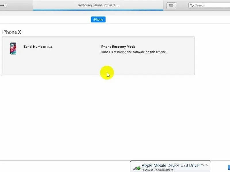

- When servicing iOS 12 iPhones, replacing baseband integrated circuits necessitates a full device restore and subsequent baseband data re-programming.
- Secure both the upper and lower layers to the test fixture, ensuring the back glass assembly is properly connected, then link the battery connector to the DC Power Supply.
- Using the provided USB cable, establish a connection between the iPhone and the computer, then utilize iTunes to initiate a restoration process. After the restoration completes, detach the USB cable, the power supply, and subsequently remove the back glass assembly.
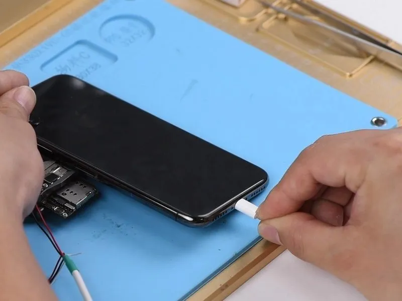
- To proceed with display assembly installation, establish a connection between the battery connector and the Power Supplier, which will initiate the device's activation sequence.
- The screen now shows the serial number and IMEI number, and the signal bars in the upper-right corner have returned to their expected appearance after selecting the icon located in the bottom-right corner, confirming the root cause of the previous "No Service" issue.Refer to the U_PMIC_E component..
Step 11
- Using a soldering iron, join the two layers by melting the solder material and creating a permanent metallic bond between them.
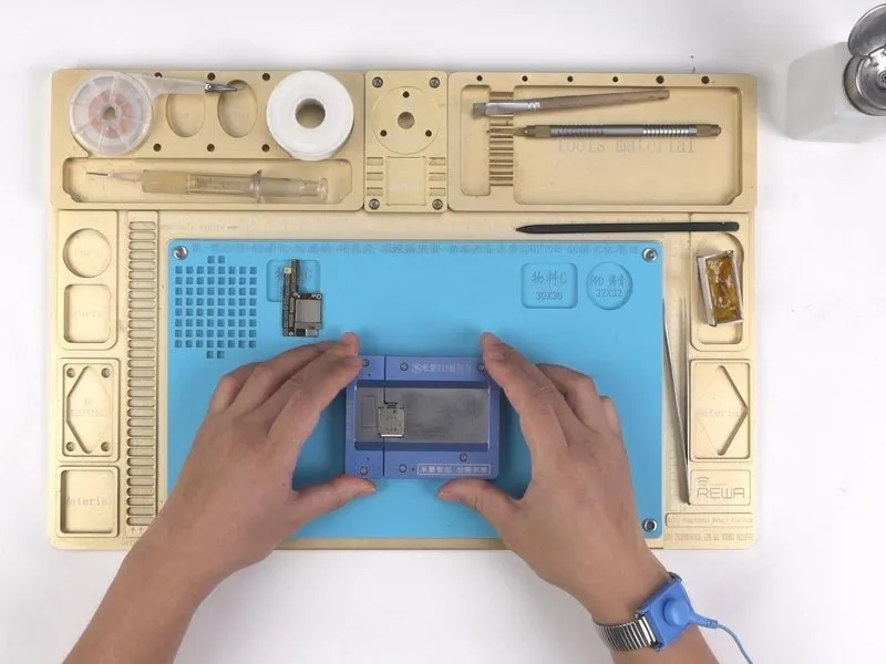
- Secure the iPhone X's lower section within the designated reballing fixture.
- Position the appropriate reballing template over the lower layer.
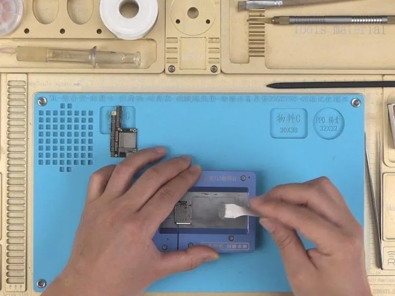
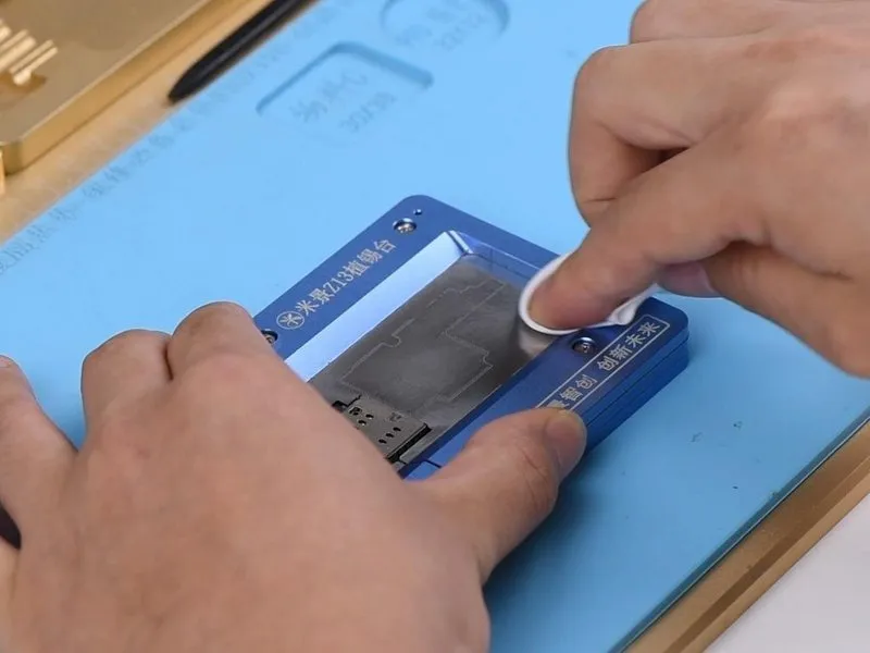
- Apply a thin, even layer of low-temperature solder paste to the stencil surface, then use a lint-free wipe to meticulously remove any excess material. Carefully lift the aligned reballing stencil afterward, verifying uniform solder paste distribution.
Step 12
- Position the lower layer assembly on the heating platform.
- Activate the heating platform and adjust its temperature to 150°C; as the solder paste liquefies, solder ball formation will begin, and after the process is finished, deactivate the platform and allow a 10-minute cooling period for the lower layer.
- Spread a thin, even layer of BGA Paste Flux across the bonding pad surface.
- Activate the heating platform while ensuring the top layer is correctly situated.
- After the platform's temperature registers 150°C, maintain that heat for a full minute. Subsequently, turn off the heating platform's power supply and allow the motherboard to cool down for a period of 10 minutes.
Step 13

- Recombine the device's components and verify functionality.
- Powering on the device initiates the standard activation sequence.
- Access the on-screen display by tapping the icon located in the lower-right corner; the device's serial number and IMEI number should then appear.
- The mobile network indicator now displays a standard signal strength, confirming resolution of the "No Service" error.
Before proceeding, ensure the component is at room temperature to prevent damage.Following verification that the issue is resolved, reassemble the device completely.