iPhone X-12 Double-stacked Board Separation & Recombination Tips
Disassembling and reassembling the dual-layered motherboard represents a critical procedure formotherboard restorationon iPhone X devices and subsequent models; even minor inaccuracies can lead to false soldering or related complications.
- REWA Academy learnershave recently communicated that the two layers frequently do not align properly during the process of repairing dual-layered motherboards.
- Significant spaces can even occur, contributing toartificial soldering.
Addressing this concern, we will provide guidance and observations regarding the separation and rejoining of dual-layered motherboards. The techniques detailed herein are applicable to iPhone X and later versions.
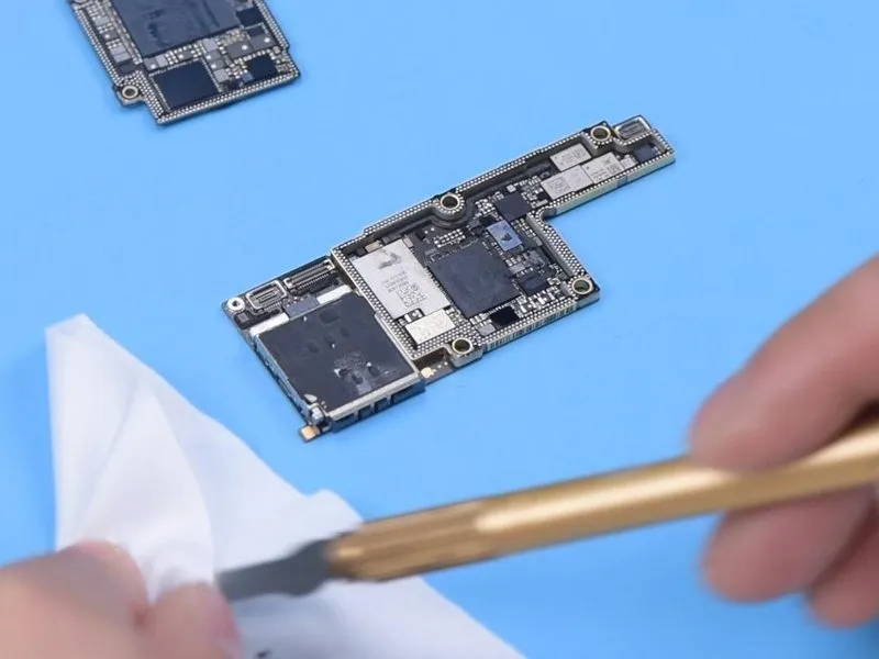
Step 1 | iPhone X-12 Double-stacked Board Separation & Recombination Tips

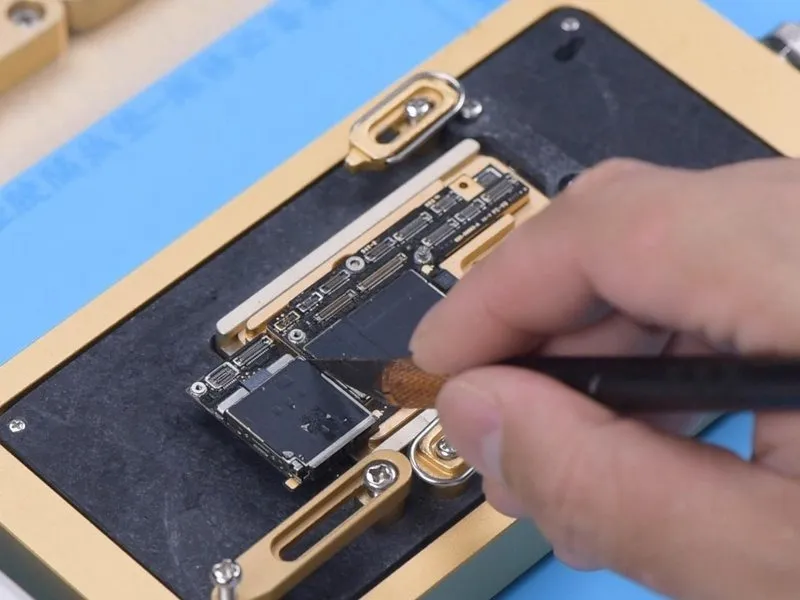

- Prior to applying heat, remove the foam layer covering the motherboard's surface.
- It is important to understand that using a hot air gun to heat a motherboard is not advised for inexperienced individuals, as this process carries a risk of uneven heat distribution and potential deformation of the board. A specialized motherboard heating platform is the recommended tool for this task.
- For easier separation of the logic board later, secure it with a screw.
- Employ a Sculpture Knife to sever the adhesive tape.
Step 2
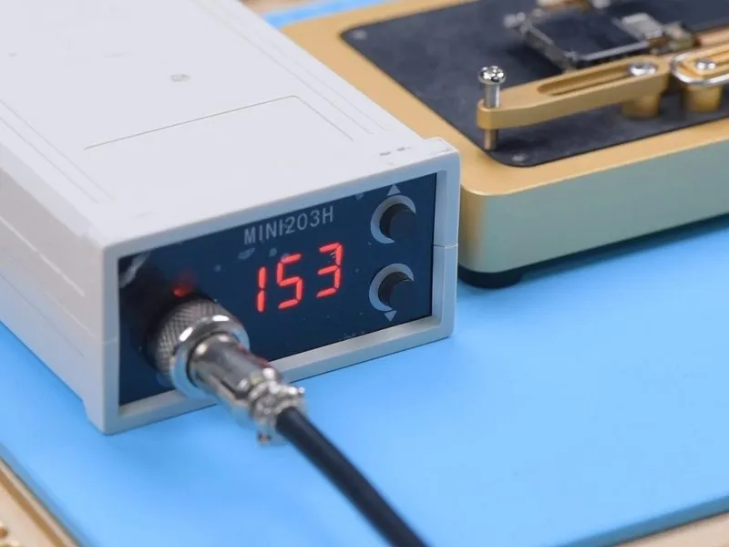
- A specialized, low-melting-point solder paste secures the logic board and intermediate layer, necessitating a carefully controlled heating platform temperature.Optimal platform temperatures should fall within the range of 155 °C to 165 °C..
- Employing tweezers, apply slight pressure to the logic board as the platform's temperature achieves 165 °C.165 °C. A detachment of the logic board indicates that the solder has transitioned to a liquid state.
Step 3

Secure the screw with a clamp to facilitate logic board detachment, subsequently enabling removal of the signal board.
Step 4
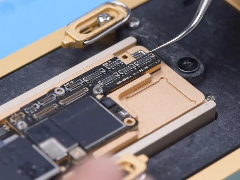
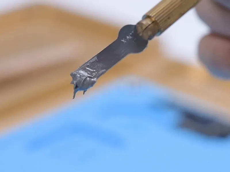
- Employ a sculpting knife to eliminate the existing thermal compound.Sculpture Knife.
- Complete removal of the thermal grease is essential; any residual compound can create a false electrical connection between the logic board and the component, mimicking a solder joint during reassembly.
- Secure the signal board within its designated holder and subsequently apply a layer of paste flux.
Step 5


- Employ a Soldering Iron to eliminate excess tin from the bonding pad's surface.Soldering IronUtilize a temperature of 365 degrees Celsius during this process, alongside Solder Wick.Solder Wick.
- Ensure the bonding pad is entirely free of residual tin, as any remaining tin will compromise future soldering operations.
- Subsequently, utilize PCB Cleaner to prepare the bonding pad's surface.PCB Cleaner.
- Apply this identical cleaning procedure to the entire logic board, exercising caution to prevent damage to surrounding components; a thorough inspection of the bonding pad's cleanliness is essential following the cleaning process.
Step 6

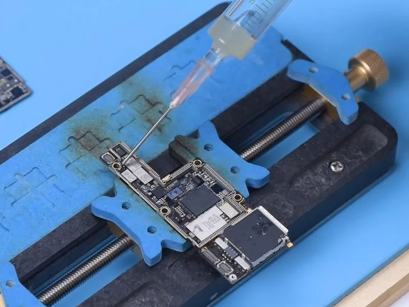
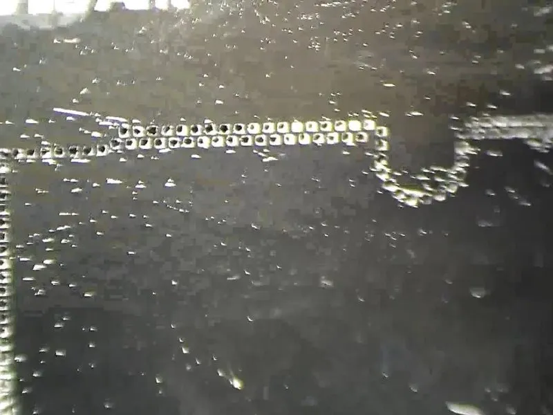
- Secure the signal board to the designated area.Position the reballing platform.Align the reballing stencil precisely, guaranteeing firm contact with the signal board's surface.
Introduce a metal plate to obstruct solder paste migration into the motherboard's separation. - Distribute a thin coating of low-temperature solder paste.Solder Pasteand subsequently eliminate surplus material utilizing a lint-free wipe.Lint-free WipeThen, detach the reballing stencil and verify the solder paste coverage on the signal board is complete.
Step 7
Maintaining a specific level of moisture in the solder paste is crucial during application.
Should the solder paste lack sufficient moisture, it will cling to the reballing stencil upon separation, potentially leading to uneven solder paste distribution on the printed circuit board and compromised soldering quality.
Step 8

- Position the signal board onto the 165 °C Heating Platform to initiate the heating process.
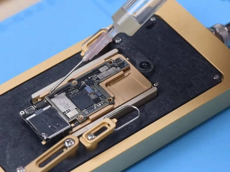
Cease the heating operation once the solder balls have fully developed. - Following the signal board's cooling, dispense a limited quantity of Paste Flux onto the surface.
Step 9
- Position the logic board in relation to the signal board, maintaining the 165 °C Heating Platform at operational temperature.
Should solder flux leakage occur, and the logic board settles, carefully reposition it using tweezers to guarantee proper contact; the adjustment should be minimal and delicate. - Following the cooling process, remove any residue from the motherboard utilizing a PCB Cleaner.
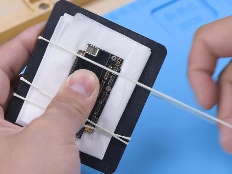
Should the motherboard exhibit warping during reassembly, secure it to a level surface and bind it with a rubber band, then apply a light, even pressure to both lateral edges, ensuring the placement of soft paper beneath the board to prevent component damage.
Step 10

Should the central bonding pad remain undamaged, an alternative reflow technique can be employed.
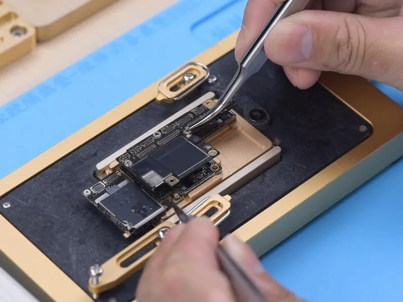
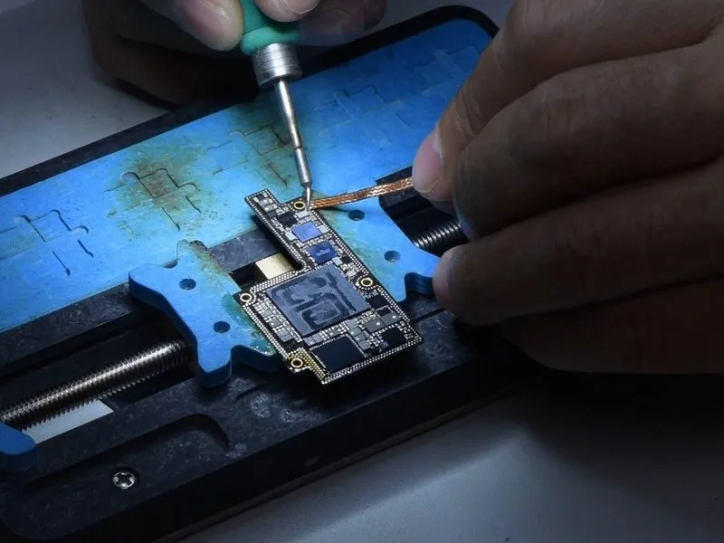
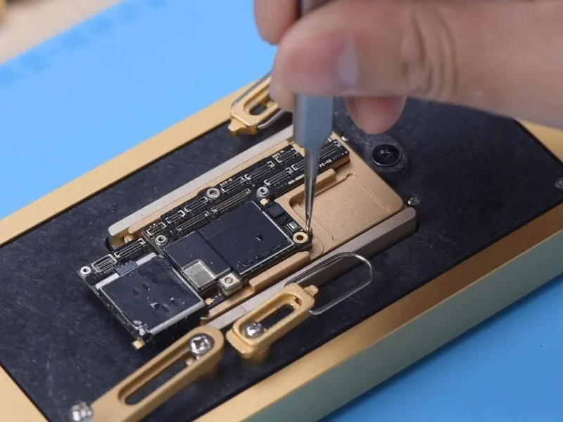
- As the solder liquefies, carefully detach the logic board from the assembly using tweezers, ensuring a vertical extraction.
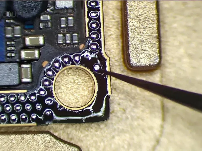
A metallic layer measuring0.05 mm in thickness, positioned near the signal board, maintains a0.05 mm separation between the logic board and the intermediate layer, mitigating the risk of solder bridging. - Following the repair procedure, thoroughly clean any residual thermal grease from the motherboard's surface.
Preserve the existing tin on the bonding pad and apply a minimal quantity of Paste Flux. - Position the logic board precisely in relation to the signal board; upon reaching a temperature of165 °C and the solder's melting point, immediately deactivate the power supply.
With the motherboard still warm, apply gentle pressure to both ends of the logic board using tweezers, guaranteeing a tight connection and preventing solder bridging or excess solder flow.