Fix unresponsive iPhone X
Prior to commencing any repair work, it is essential to disconnect the device from all electrical power supplies.
- Necessary Tools:A Phillips head screwdriver is needed.
Consult the device's user manual for detailed information pertaining to your specific model and any supplementary safety guidelines.
Step 1 | iPhone X
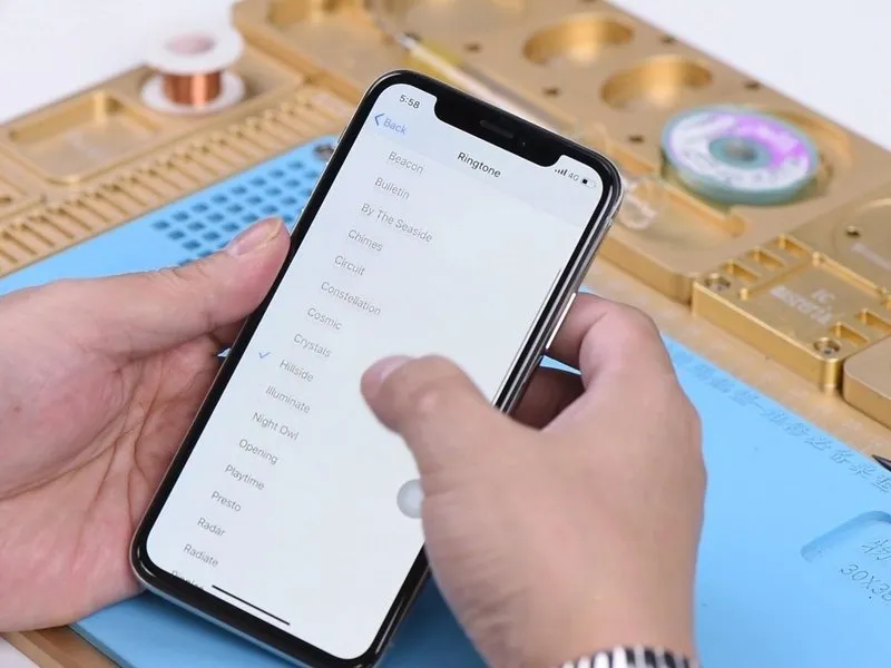

- Navigate to the Settings menu, then select Sounds & Haptics.
- If everything functions correctly, proceed.
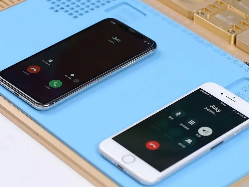
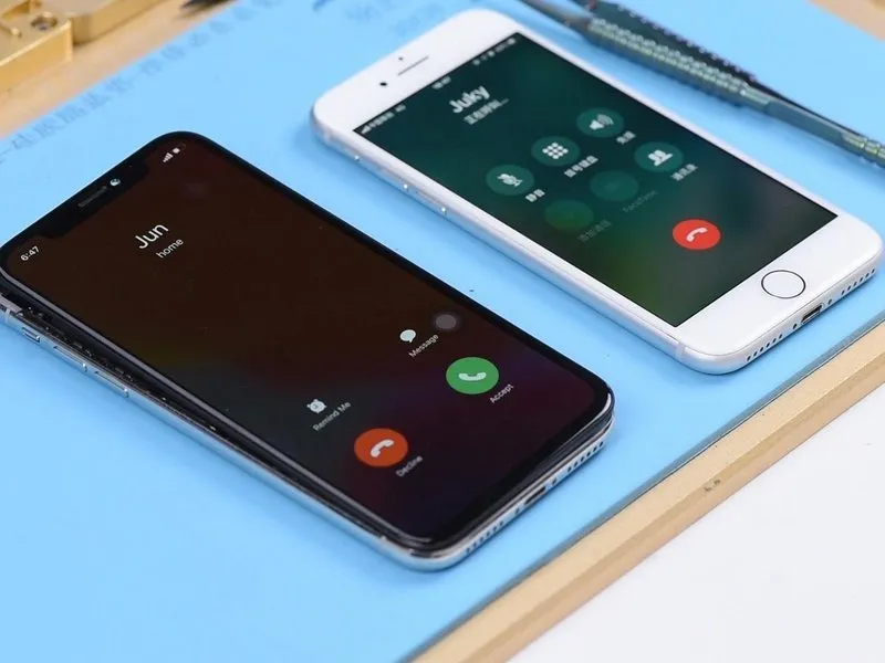
- While the display remains active, initiate a phone call utilizing a verified functional phone; the decline and answer buttons should become visible on the screen.
- Deactivate the display, then make a call using a confirmed working phone. If the device exhibits a complete lack of response, engage the power button to reactivate the screen, at which point the decline and answer buttons should be observable.
Step 2
- The baseband wake signal's underlying circuitry may be experiencing operational failures, based on the observed behavior.
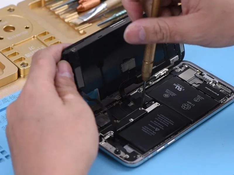
- Disassemble the device, beginning with battery disconnection. Subsequently, remove the display unit and extract the motherboard.
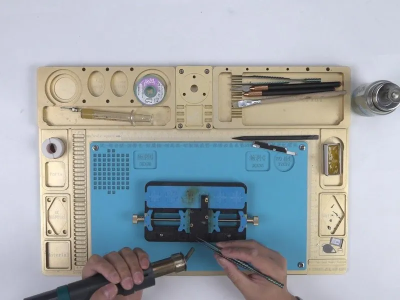
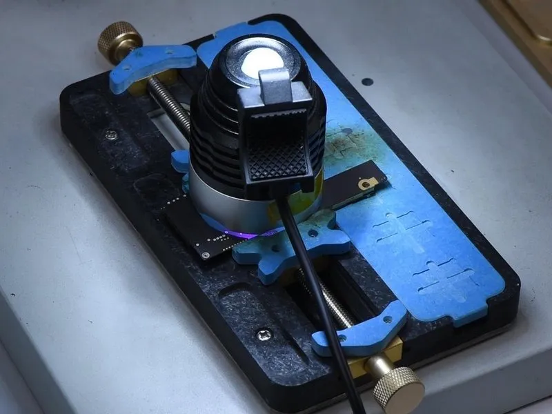
- Secure the motherboard to the PCB Holder for stability.Utilize aHot Air Gun, maintaining a temperature of 200°C and an airflow rate of 3.
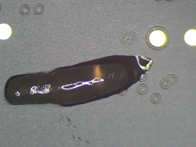
- Carefully peel away the thermal dissipation sticker adhered to the rear surface of the motherboard.
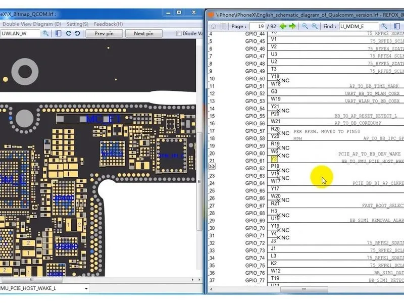
- Initiate the bitmap software application and identify the signal labeledBB_TO_PMU_PCIE_HOST_WAKE_LGiven the possibility of failures within the wake signal's associated circuits, an alternative approach involves sourcing the wake signal from the WiFi circuitry.
- Similarly, locate the signal designatedWLAN_TO_PMU_HOST_WAKETo facilitate troubleshooting, a temporary connection can be established betweenPP101_E-1 (the designated test point for the baseband wake signal) andPP7611_W-1 (the designated test point for the WiFi wake signal) via a wire jumper.
Step 3
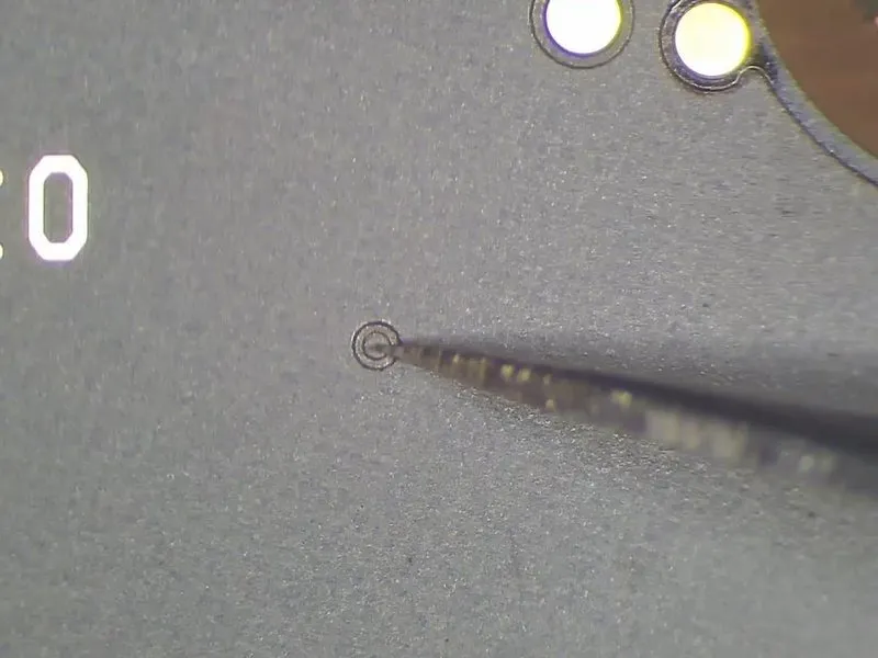
- Begin by removing the insulating material covering the designated test locations. Subsequently, deposit solder paste onto the two bonding areas. Utilize a Soldering Iron, maintaining a temperature of 365°C, to facilitate the process. Apply solder paste to the bonding pads to ensure they are properly tinned.Soldering Iron at 365°C
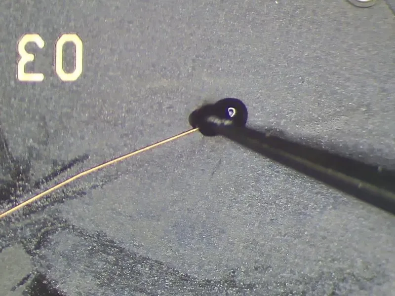
- Establish a connection betweenPP101_E-1andPP7611_W-1using 0.02mm Enameled Copper Wire.
Step 4
- Apply a layer of UV-curable solder mask to the exposed wire to provide insulation and protection.
- Proceed with reassembling the mobile device and initiating a series of tests; initially, verify functionality with the display deactivated, and subsequently, if all tests conclude successfully, the identified fault has been resolved.