Fix iPhone X with Distorted Sound
Prior to commencing any repair work, it is essential to disconnect the device from all electrical power supplies to guarantee safety.
- Necessary Tools:A Phillips head screwdriver is needed for this procedure.
Consult the device's user documentation for precise specifications related to your particular model and any further safety guidelines.
Step 1 | Fix iPhone X with Distorted Sound
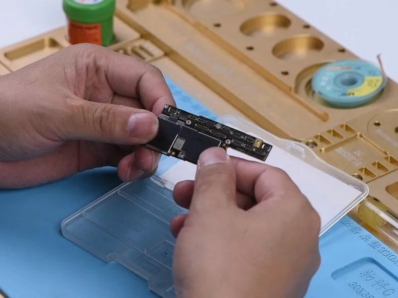

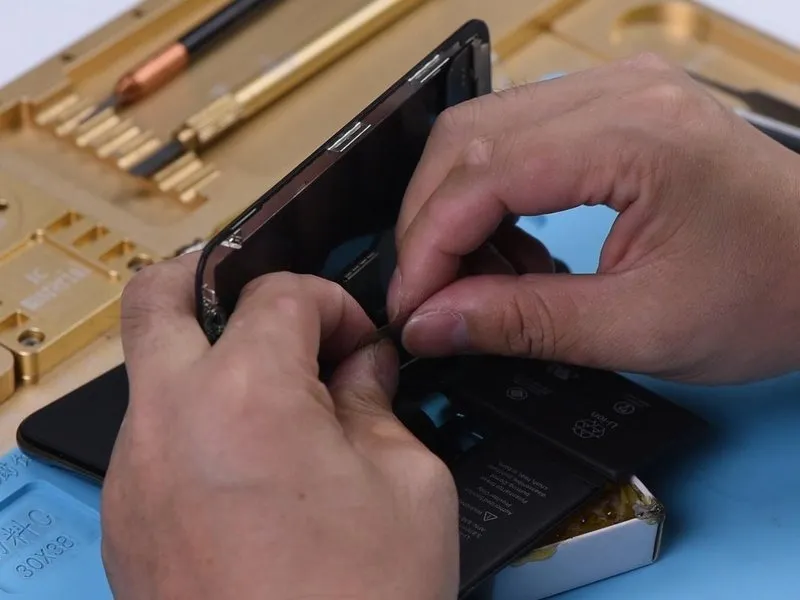
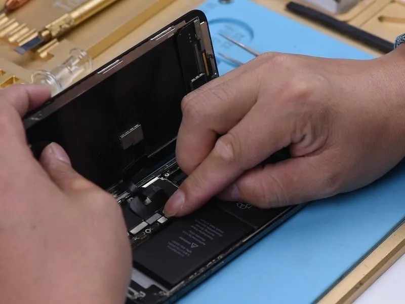
- Initially, perform a visual assessment of the motherboard's condition.A cosmetic evaluation is required.Confirm the motherboard exhibits no physical distortions or signs of water exposure.
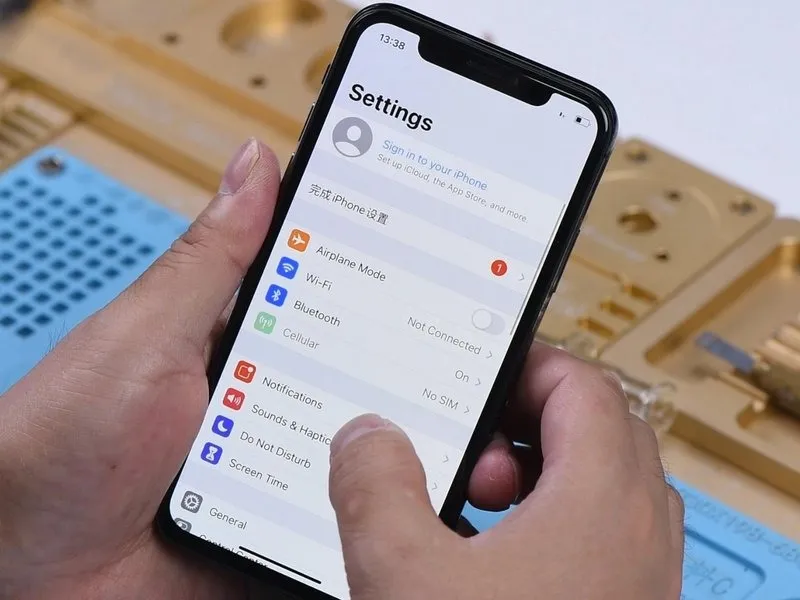
- Subsequently, mount the motherboard onto the device for preliminary testing; observe that the device powers on without issue. Proceed to the Settings menu, specifically navigating to Sounds & Haptics, and increase the volume level. Initiate playback of ringtones, noting the presence of audible interference within the audio output.
Step 2

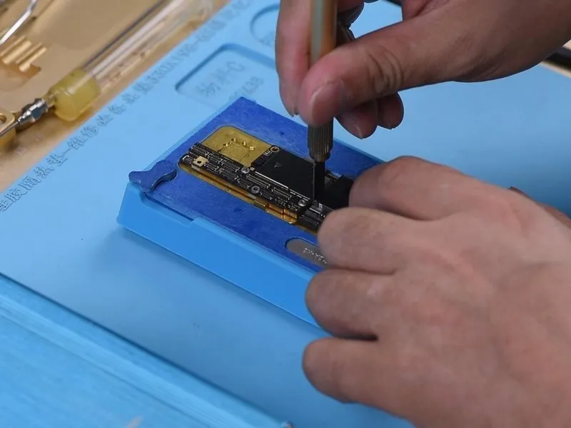
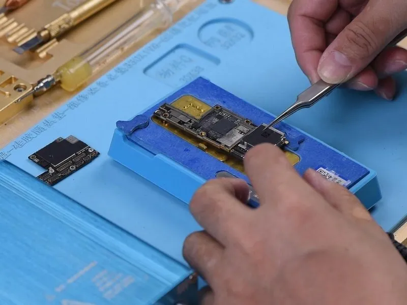
- Using appropriate measurement techniques, assess the electrical characteristics of speaker-related circuits connected to the charging port connector, ensuring the device is powered down beforehand. Subsequently, disconnect the motherboard. Perform a diode mode test on pin 1, pin 3, pin 5, and pin 45 on the J6400, confirming that the resulting diode values fall within expected norms.1, pin 3, pin 5, and pin 45 on the J6400. The diode values are normal.
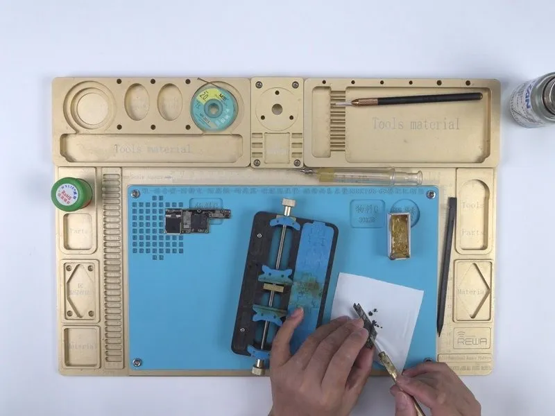
- For more in-depth analysis, the motherboard must be carefully separated from the rest of the device. Employ a Sculpture Knife to precisely cut through the protective shielding paper.Sculpture KnifePlace the motherboard on a Heating Platform and raise its temperature to 165°C. Once the temperature reaches 165°C, carefully remove both the logic board and the signal board.
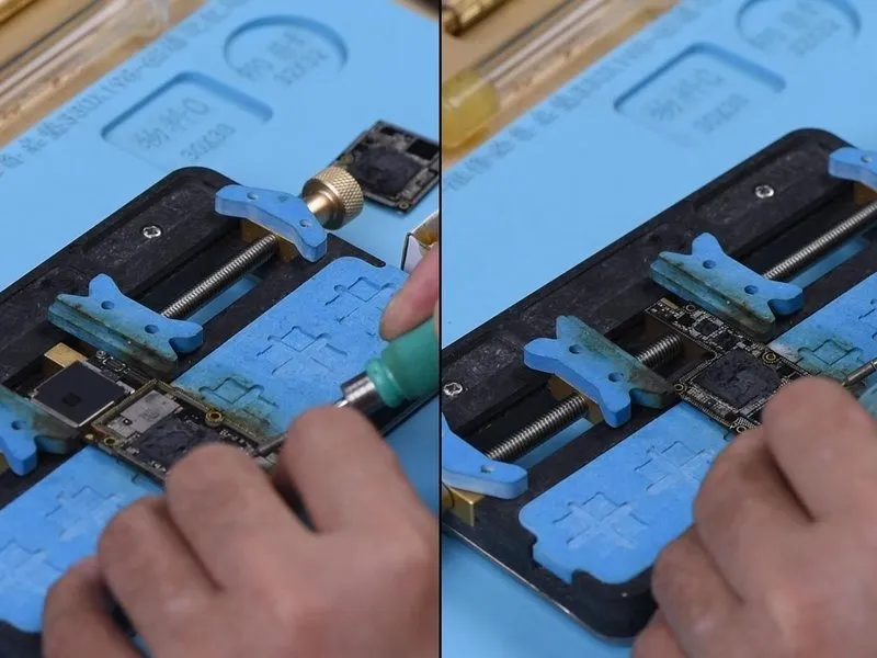
- Secure the signal board within a designated holder. Utilize a Soldering Iron set to 365°C, along with soldering wick, to effectively remove excess solder from the bonding pad. Apply the identical procedure to eliminate solder residue from the bonding pad on the logic board.
Step 3


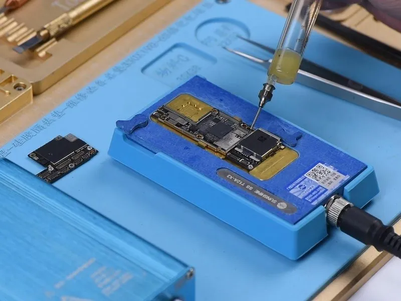
- Using a specialized sculpting knife, carefully eliminate the existing thermal compound.A sculpting knife is the recommended tool for this process.Employ a PCB cleaner to thoroughly cleanse the motherboard's surface, then secure both the signal board and logic board within the Testing Fixture.
Step 4

- Attach the Test Extension Cable, secure the Testing Fixture, and subsequently establish connections for the charging port flex cable, the battery, and the display. To initiate the boot sequence, briefly create a connection to the ground pin of J4300.9 Following this procedure, the device should power on in its standard operational mode.
Step 5


- Navigate to Settings, then select Sounds & Haptics. Because ringtones are functioning correctly, the issue likely stems from improper soldering on the motherboard's internal layers.
The subsequent step involves reconnecting the logic board and signal board; initially, the signal ball requires reballing. - Securely affix the signal board onto the Reballing Platform. Position the Reballing Stencil precisely. Distribute a uniform layer of low-temperature solder paste. Subsequently, remove the Reballing Stencil.
Step 6
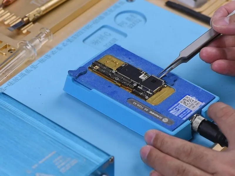
- Position the signal board onto the Heating Platform.
Warm the signal board to a temperature of 165°C, allowing solder balls to develop.
Deactivate the power supply and permit the motherboard to cool down for a duration of 5 minutes.
Distribute Paste Flux. - Carefully position the logic board in relation to the signal board.
Maintain heating of the motherboard at 165°C on the Heating Platform.
After reaching 165°C, sustain the heat for an extra minute to guarantee a secure connection.
Deactivate the power supply and allow the motherboard to cool for a further 5 minutes prior to detachment.
Step 7
- Carefully position the main circuit board within the device's housing.
Reestablish electrical connections for the screen and power cell.
Successful completion of the reassembly process should result in the device powering up as expected.
Verify audio functionality, confirming the absence of any unusual sounds or distortions.