iPhone SE 2020 Front Camera And Sensor Cable Replacement
To perform the front camera and sensor cable replacement on your iPhone SE 2020, adhere to the instructions detailed in this document.This repair procedure specifically addresses the assembly incorporating the microphone, front camera, proximity sensor, and ambient light sensor.The replacement process involves handling a delicate assembly containing multiple interconnected components.The microphone, responsible for audio recording, is an integral part of this front camera assembly.The front camera module, used for selfies and video calls, is included within the unit being replaced.The proximity sensor, which detects nearby objects to disable the screen during calls, is also part of this assembly.The ambient light sensor, which adjusts screen brightness automatically, is another component within the assembly.Careful handling is essential to avoid damage to the microphone, camera, or sensors during the replacement.Disconnection and reconnection of the cable requires precision to prevent damage to the connector pins.Ensure proper alignment of the assembly during installation to guarantee correct functionality of all sensors.Successful completion of this repair restores front camera and sensor functionality to the iPhone SE 2020.
Step 1 | Remove the pentalobe screws
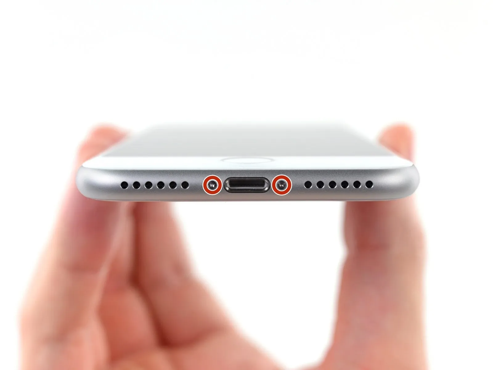
- To initiate the repair process, ensure the iPhone's battery level falls below 25% by fully depleting it.A fully charged lithium-ion battery presents a fire and/or explosion hazard if it sustains accidental physical damage.Deactivate the iPhone's power supply prior to commencing the disassembly procedure.
- Utilize a specialized tool to extract the pair of 3.5 mm pentalobe fasteners located along the iPhone's lower edge.
- Separating the iPhone's display assembly will irreversibly damage its integrated waterproofing capabilities.
- Procure replacement waterproof seals beforehand to prevent liquid ingress, or exercise extreme caution to avoid moisture exposure during reassembly if new seals are not used.
Step 2 | Mark your opening picks


- Excessive insertion of a prying tool poses a risk of device damage; implement the following procedure to identify a safe insertion depth.
- Using a precise measuring tool, determine a distance of3 millimetersfrom the tool's distal end and visibly indicate this point on the prying tool using a permanent marking instrument.
- For enhanced precision, consider applying distinct markings at various points along the tool's edges, each representing a different measurement.
- As an alternative method for limiting insertion depth, securely affix a coin to the prying tool's tip, positioning it3 millimetersfrom the foremost edge.
Step 3 | Anti-Clamp instructions


The following three actions detail the operation of the Anti-Clamp, a specialized instrument developed to simplify the initial separation process; if this tool is unavailable, proceed to the subsequent three steps for an alternative approach.
A separate instructional document provides comprehensive details regarding the Anti-Clamp's utilization.
- To release the locking mechanism, retract the blue handle, which will disengage the Anti-Clamp's gripping arms.
- Carefully position the arms across either the left or right side of the iPhone's frame.
- Place the suction cups close to the lower edge of the iPhone, situated directly above the home button—one on the front face and one on the rear.
- Apply pressure by compressing the cups together to establish a secure vacuum seal on the intended surface.
- Should the iPhone's exterior prove excessively smooth, hindering the Anti-Clamp's ability to maintain adhesion, applying adhesive tape can enhance surface friction.
Step 4


- Advance the blue handle to engage the locking mechanism on the arms.
- Rotate the handle in a clockwise direction.Continue the rotation until a full circle, or approximately 360 degrees, has been completed.The process should conclude when the cups begin to exhibit signs of deformation.
- Maintain proper alignment of the suction cups; if misalignment occurs, slightly release the suction cups and readjust the arms.
Step 5


- Employing an iOpener, introduce it between the Anti-Clamp’s arms.Alternative heating methods, such as hair dryers, heat guns, or hot plates, are acceptable; however, exercise caution to prevent damage to the display or internal battery due to excessive temperatures.Position the iOpener to rest along the lower edge of the iPhone’s casing.Allow a sixty-second interval for the adhesive to soften and facilitate separation.Introduce an opening tool into the newly formed space.
- Should the Anti-Clamp fail to generate an adequate separation, increase the localized heat and adjust the handle’s position by ninety degrees.
- Incremental handle rotations, not exceeding ninety degrees, are recommended, accompanied by sixty-second pauses between adjustments.Rely on the Anti-Clamp’s pressure and the passage of time to achieve separation.The iOpener should be heated to facilitate separation.
- Carefully manage the heat source to avoid battery or display damage.
- A one-minute wait allows the adhesive to weaken.
- A specialized opening pick is required for insertion.If insufficient separation is achieved, apply additional heat and rotate the Anti-Clamp handle.Avoid excessive handle rotation to prevent damage; wait one minute between adjustments.
- The Anti-Clamp and time are essential for effective separation.The iOpener’s purpose is to create an initial separation point.Adhesive release requires a period of time following heat application.
Step 6 | Heat the display
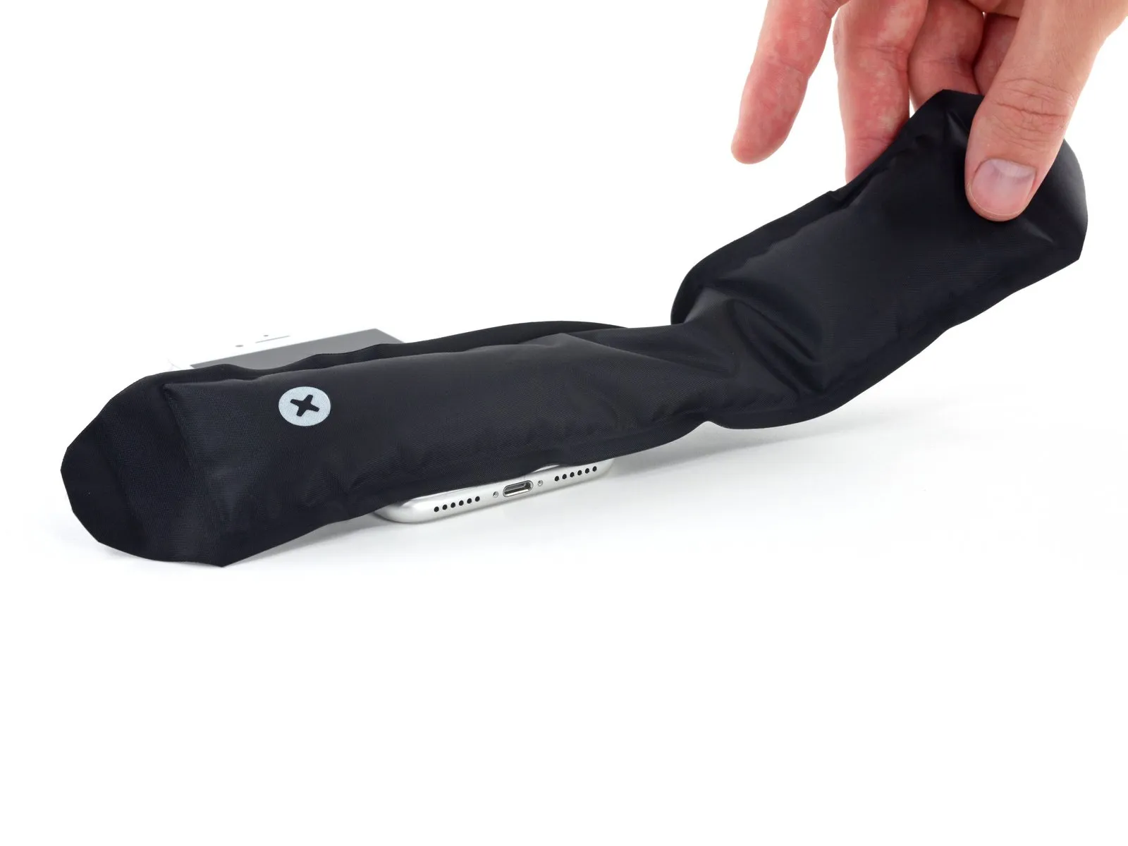
The subsequent procedures illustrate the process of detaching the display assembly with the aid of a specialized suction device.
- Applying heat to the phone's bottom border facilitates the loosening of the adhesive bonds holding the screen in place, simplifying the separation process.
- Employing a hairdryer or utilizing an iOpener is recommended for warming the lower edge.The iOpener, if used, should be applied to the phone's lower edge for approximately 90 seconds to reduce the adhesive's tackiness.This heating period serves to soften the adhesive securing the display, easing the separation procedure.
Step 7 | Separate the display
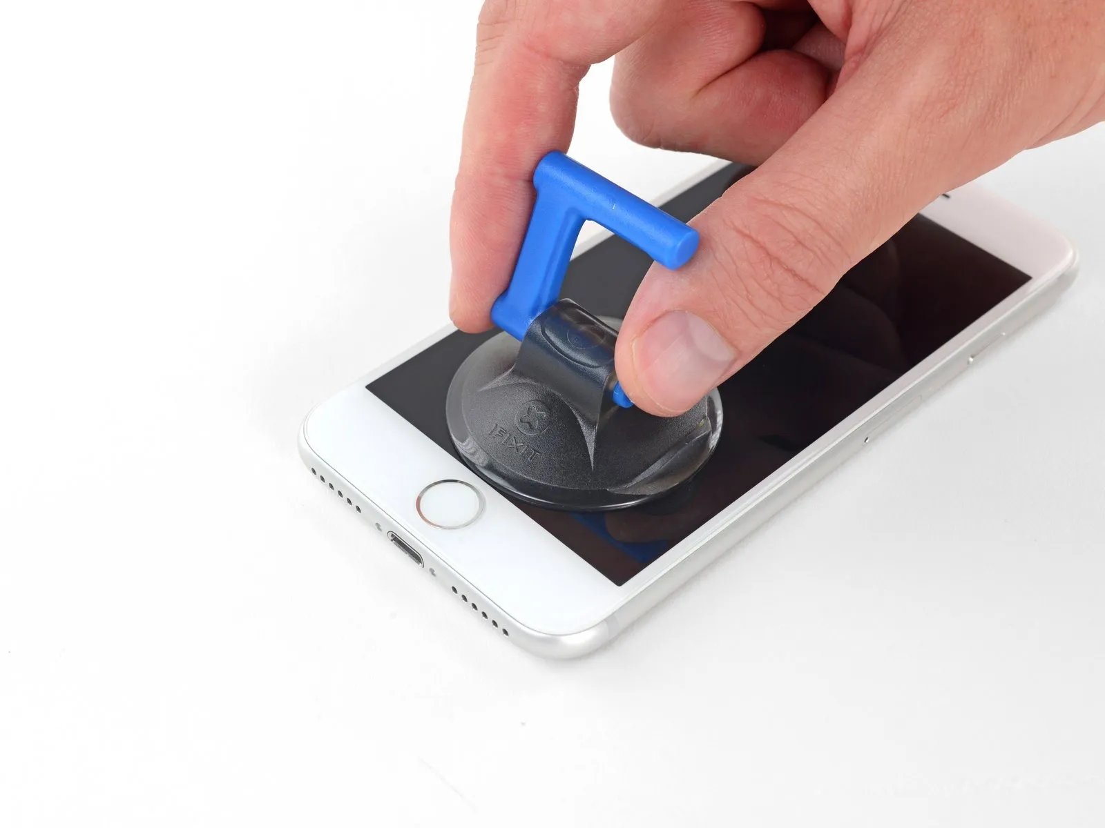

Securely affix a suction cup to the lower portion of the front panel, positioning it directly over the home button area.
Ensure the suction cup's surface area remains clear of the home button's position to guarantee a proper airtight bond between the cup and the glass.
Step 8
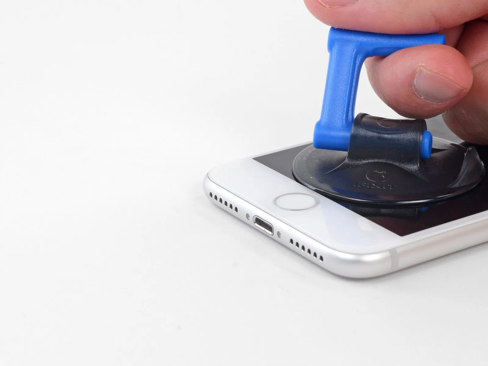


- Maintain consistent, forceful upward traction on the suction cup to generate a minimal separation between the display assembly and the device's border.
- Introduce an opening tool into the newly formed separation.
- Due to the robust nature of the waterproof sealant securing the display, a considerable amount of force might be necessary to initially create this separation; if encountering difficulty, apply additional heat and gently oscillate the display to reduce adhesive strength until sufficient space exists for tool insertion.
Step 9
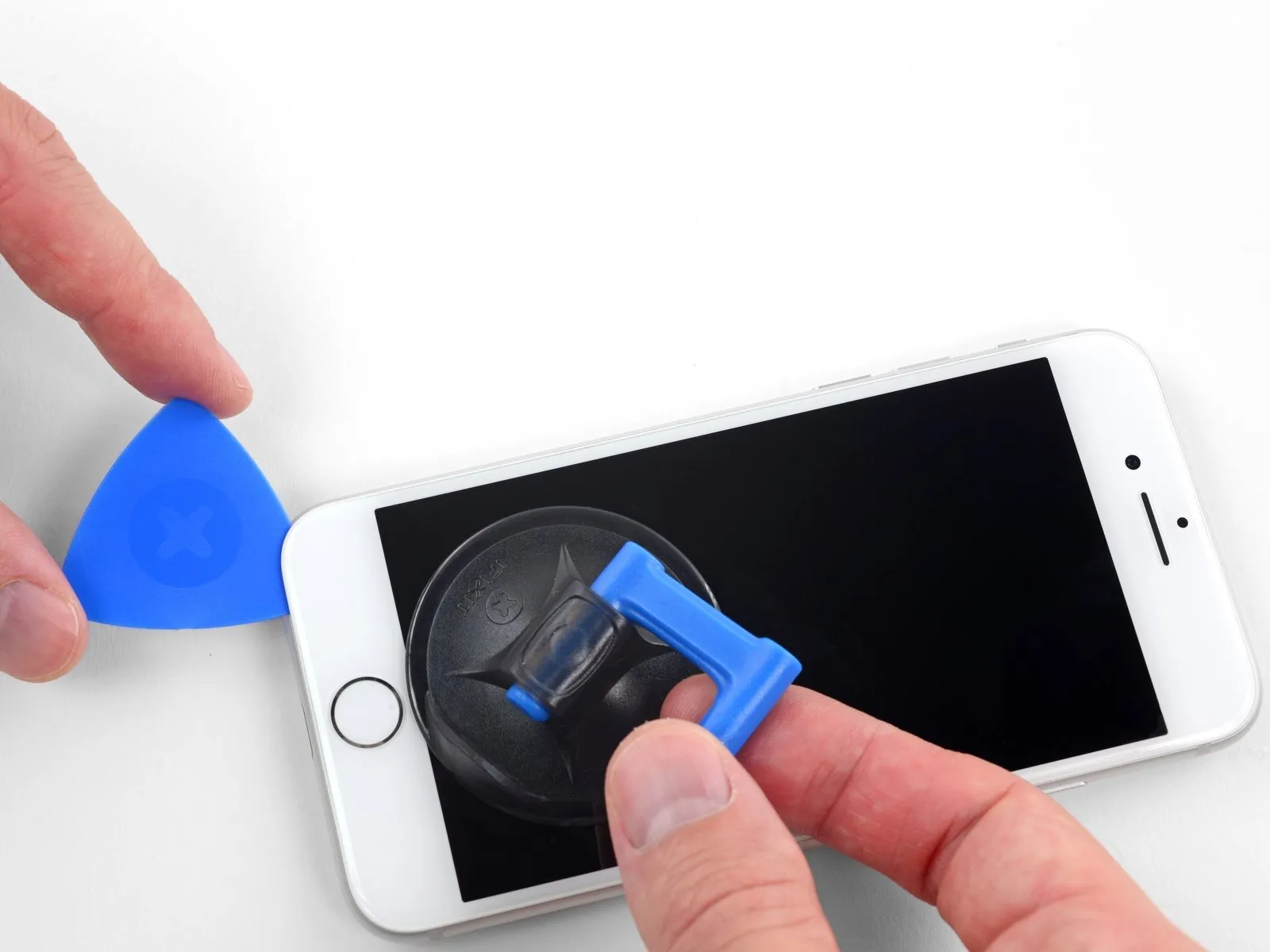


- Begin separating the display assembly from the chassis by inserting a prying tool into the lower edge of the phone's left side, then carefully advancing it towards the volume buttons and the silent switch while disrupting the adhesive seal.
- Cease the separation process when the tool reaches the upper-left portion of the display's surface.
- Avoid attempting to dislodge the display's upper edge from the rear housing, because it is secured with fragile plastic retaining clips that are susceptible to damage.
Step 10 | Screen information

Fragile wiring is situated along the iPhone's right side; avoid inserting any tools in this area to prevent potential cable damage.
Step 11
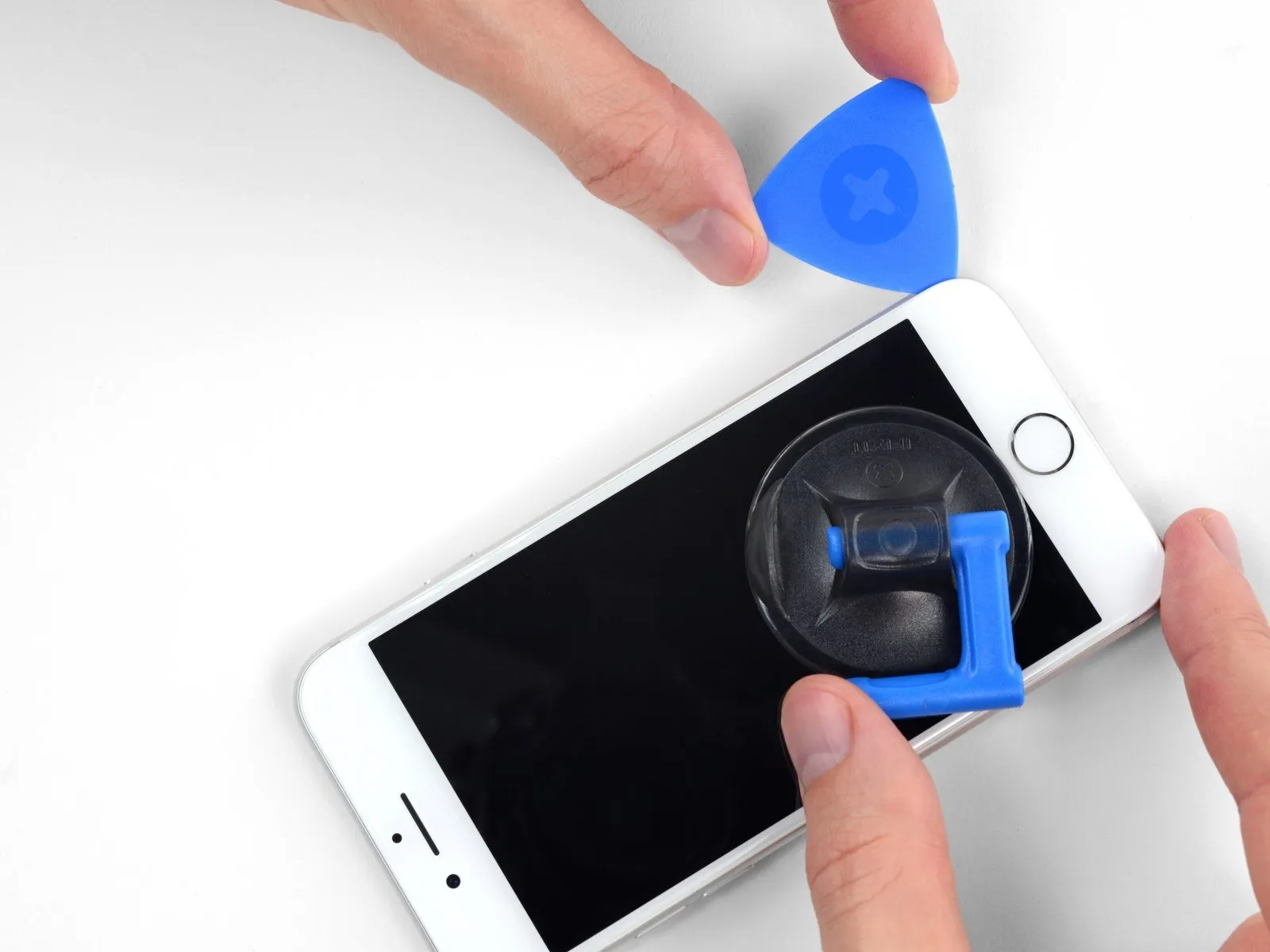


- To release the adhesive securing the iPhone, reposition your opening tool at the lower-right edge and maneuver it along the corner and up the right side.
- Ensure the tool's insertion depth remains under 3 mmto prevent potential damage to the delicate display cable connections.
Step 12


- Employing a delicate upward force on the suction cup facilitates separation of the display's lower boundary.
- The display's elevation should be restricted to a maximum angle of 15 degrees to prevent potential damage to the flexible ribbon cable connectors.Exceeding this angular limit introduces a risk of stress or rupture to the display's ribbon cables.A small protrusion on the suction cup's surface serves as a convenient point for its detachment from the display's front surface.
- To disengage the suction cup, grasp and exert traction on this designated nub.
Step 13
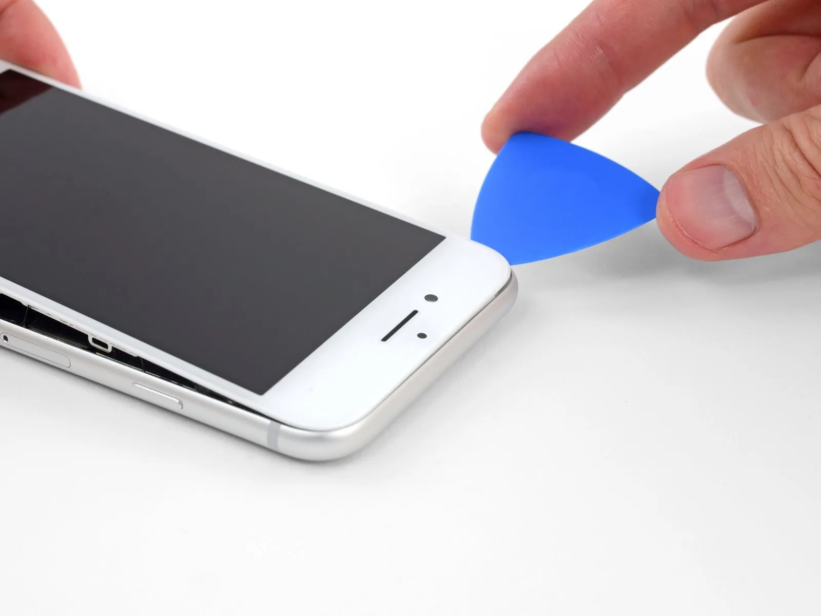

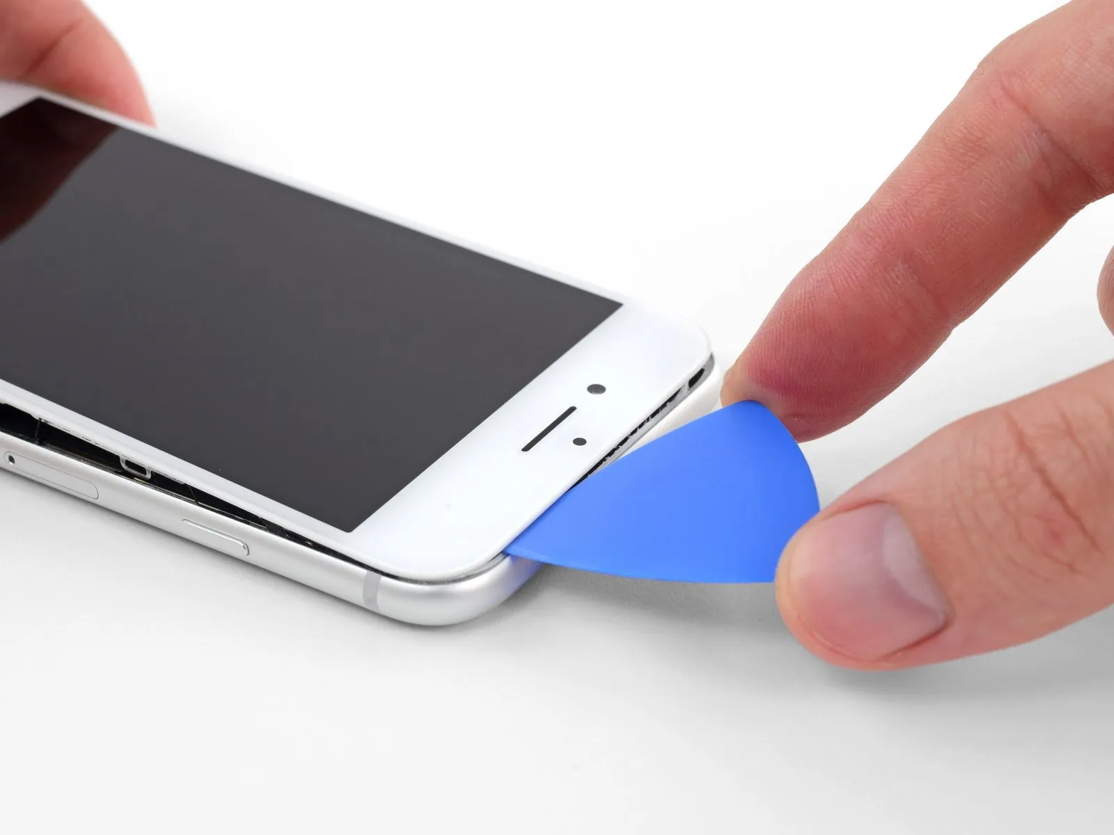
- Using a specialized opening tool, carefully insert it beneath the display's surface, initiating at the upper-left corner and progressing along the top edge, to release the remaining adhesive securing the screen.
Step 14


- To release the retaining clips securing the display assembly to the rear case, move the display downwards, shifting it away from the phone's upper boundary.
Step 15


- Initiate the iPhone's disassembly process by pivoting the display assembly upwards, commencing from the left edge, mirroring the action of opening a book's cover.
- Refrain from completely disconnecting the display at this stage, because multiple delicate ribbon cables maintain its electrical connection to the device's main circuit board.
- Secure the display in an upright position using a support to prevent it from shifting during subsequent repair procedures.
Step 16 | Disconnect the battery


- Detach the four Phillips screws that fasten the lower display cable bracket to the logic board.The screws used for this attachment have differing lengths, specifically two measuring 1.3 millimeters and two measuring 2.8 millimeters.Maintain meticulous organization of all screws throughout this repair process to ensure proper placement during reassembly.
- Incorrect screw placement during reassembly can result in irreversible damage to the device.
- Carefully note the location of each screw to facilitate correct reinstallation.
- Proceed to remove the bracket from the device.
Step 17


- Employing the tip of a spudger, carefully disengage the battery connector from its corresponding receptacle on the logic board.
To inhibit unintended power delivery to the device during the repair process, gently deflect the battery connector cable slightly outward from the logic board's socket.
Step 18 | Disconnect the display and digitizer


- Employ the tip of a spudger to disengage the lower display connector from its receptacle.
For reattachment, depress one edge of the connector until a click is heard, then repeat the process on the opposing edge; avoid applying pressure to the central portion, as misalignment can result in bending and irreversible damage to the connector.
Step 19


- Employ the tip of a spudger tool to release and separate the connector securing the second lower display cable.
Step 20


- To detach the bracket that covers the front panel sensor assembly connector, first eliminate the three screws with a 1.3 mm Phillips head.The screws holding the bracket in place must be taken out to allow access to the connector.Utilize a Phillips screwdriver of 1.3 mm size to unscrew and remove the fasteners.
Following screw removal, the bracket can now be taken away from the assembly.
Step 21


Step 22 | Remove the display assembly
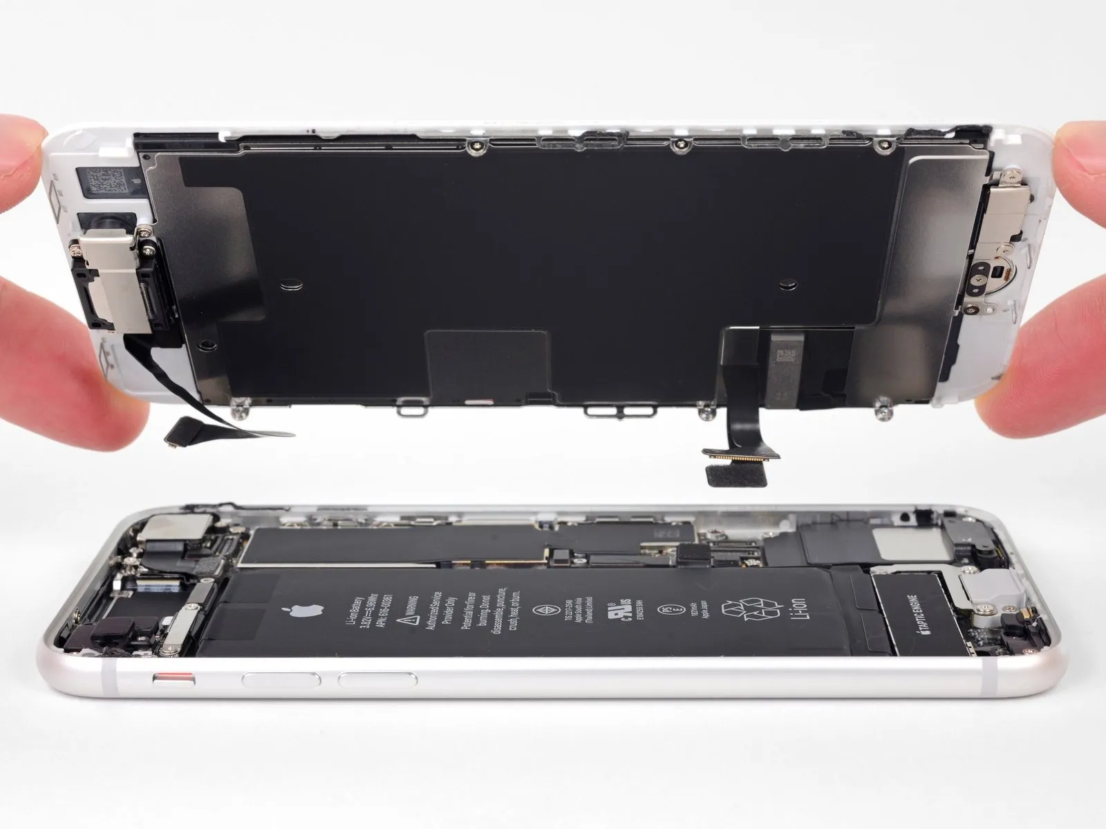
- Detach the display unit from the device.
- If edge adhesive replacement is desired during reassembly, halt the process at this stage.
Step 23 | Remove the earpiece bracket

- Detach the top earpiece bracket from the front panel by eliminating the fasteners that hold it in place.The bracket is affixed using three Phillips head screws.Specifically, two screws with a 2.6-millimeter diameter are used.
- Additionally, a single screw measuring 1.8 millimeters in diameter is also present.Carefully unscrew these fasteners to release the bracket.
- Ensure proper identification of each screw size before removal.The screws must be removed to allow for disassembly of the earpiece assembly.
Step 24

Step 25 | Move the front-facing camera


Step 26 | Remove the earpiece speaker

- A single fastener with a diameter of 1.8 millimeters is utilized.The second fastener employed measures 2.3 millimeters in diameter.These screws hold the speaker in place.
- Carefully unscrew the fasteners to avoid damaging surrounding components.Ensure proper alignment when removing the screws.The speaker is affixed using these two distinct screw sizes.
Step 27

Step 28 | Remove the front camera and sensor cable

Allow approximately 120 seconds for the adhesive to become pliable prior to proceeding with subsequent repair actions.
Step 29


- Employ the tip of a spudger to carefully dislodge the proximity sensor from its housing on the device's front surface.Ensure the tool's insertion extends completely beneath the sensor to facilitate detachment from the underlying transparent plastic component.Applying force solely to the cable risks severing the sensor from its connector, necessitating a replacement.
- The potential for sensor/cable assembly separation is inconsequential should a replacement of that entire unit be already planned.
Step 30


- Utilizing a spudger's pointed end, carefully insert it beneath the ambient light sensor's flexible cable connection.Gently elevate the sensor assembly from its retaining structure with the spudger.This action disengages the ambient light sensor from its mounted position.
Step 31


Utilize a specialized opening tool to carefully disengage the adhesive securing the front camera cable assembly, facilitating separation of the camera and sensor cable.
Step 32

Disconnect and detach the assembly containing the front-facing camera and associated sensor wiring harness.