iPhone SE Volume Controls Replacement
Follow these instructions to detach the button covers associated with the ringer switch and volume controls on your iPhone SE; please note that this procedure focuses solely on the covers and does not involve the removal or servicing of the internal switches themselves.
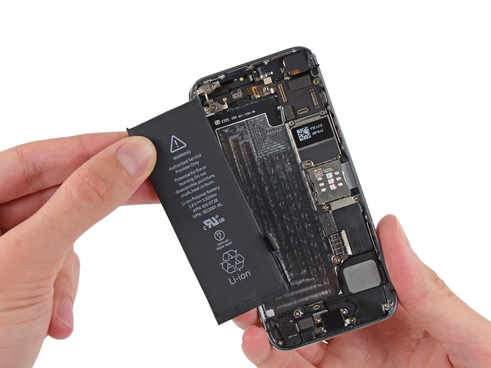
Performing this repair necessitates disconnecting the battery; because the adhesive securing the battery is designed for single use, ensure you have replacement adhesive strips available prior to commencing the process, or alternatively, utilize double-sided tape to secure the battery, as it is held firmly within the device to prevent movement.
These button covers are designed to be interchangeable with components originally intended for the iPhone 5s.
Step 1 | Removing the Pentalobe screws

Initiate the repair process with this first step:As a critical safety precaution, ensure your iPhone's battery level is depleted to less than 25% prior to commencing work; a fully charged lithium-ion battery presents a significant fire or explosion hazard if compromised by a puncture.
Deactivate the device's power supply to prevent any electrical issues during the disassembly procedure.
Using an appropriate screwdriver, extract the pair of 3.9 mm Pentalobe screws located on both sides of the Lightning connector.
Deactivate the device's power supply to prevent any electrical issues during the disassembly procedure.
Using an appropriate screwdriver, extract the pair of 3.9 mm Pentalobe screws located on both sides of the Lightning connector.
Step 2 | Taping the display glass


Proceed to step 2.To mitigate the risk of additional shattering and potential injury, secure any fractured display glass with tape if damage is present.
Apply strips of transparent packing tape across the iPhone's screen, ensuring they overlap to completely cover the entire front surface.
This method will restrain loose glass fragments and maintain the display's stability while applying leverage to separate it.
Always utilize safety glasses to safeguard your vision from any dislodged glass particles that may occur during the repair process.
Step 3 | Display separation prevention


Phase Three:The subsequent procedures involve lifting the display assembly away from the phone's chassis. This component consists of a glass screen bonded to a plastic bezel reinforced with metal clips.
It is essential to ensure the entire display assembly is raised uniformly, irrespective of the chosen tool.
Should the glass layer detach from the plastic frame, as illustrated in the initial image, insert a plastic prying tool into the gap between the plastic frame and the metal phone body to disengage the metal clips from the casing.
When reassembling a device with a detached display bezel, applying a narrow adhesive strip between the plastic bezel and the glass can help maintain closure.
Step 4 | Anti-Clamp instructions


Phase Four:The subsequent two procedures illustrate the function of the Anti-Clamp, a specialized instrument developed to simplify the initial separation process. Should you choose not to utilize the Anti-Clamp, proceed to the steps located further down for an alternative approach.
Detailed instructions regarding the Anti-Clamp's operation are available in this separate documentation.
To release the locking mechanism, draw the blue handle in a rearward direction, disengaging the Anti-Clamp's gripping arms.
Carefully position the arms across either the left or right side of your iPhone's frame.
Place the suction cups close to the lower edge of the iPhone, situated directly above the home button; one cup should be positioned on the front surface, and the other on the rear.
Apply pressure by compressing the cups together, establishing a secure vacuum seal on the intended area.
In cases where the iPhone's exterior is excessively smooth, preventing adequate adhesion by the Anti-Clamp, employ the provided tape pad to generate a more textured surface for improved grip.
Step 5


Proceed to step 5:Advance the blue handle towards the front to secure the arms in their locked position.
Rotate the handle clockwise a full 360 degrees, or continue until the suction cups begin to expand.
Confirm that the suction cups maintain their parallel orientation; should they start to deviate, slightly release the suction cups and readjust the arms.
Introduce an opening pick beneath the display screen once the Anti-Clamp has generated a noticeable separation.
Should the Anti-Clamp fail to produce an adequate gap, rotate the handle by 90 degrees.
Avoid rotating the handle excessively, limiting turns to a quarter rotation at a time, and pausing for several seconds between adjustments, allowing the Anti-Clamp and time to facilitate the separation.
Step 6 | Manual Opening Procedure

In the absence of an Anti-Clamp tool, a solitary suction cup can be employed to elevate the front panel.
Apply a suction cup to the display surface, positioned directly above the home button's location.
Ensure the suction cup establishes full contact with the screen's surface to achieve a secure and airtight bond.
Apply a suction cup to the display surface, positioned directly above the home button's location.
Ensure the suction cup establishes full contact with the screen's surface to achieve a secure and airtight bond.
Step 7 | Start lifting the front panel assembly

The front panel is secured using clips, and numerous flexible ribbon cables provide its electrical connections to the internal components of the phone. The objective at this stage is to disengage the clips and only partially open the device to permit cable disconnection, requiring deliberate and cautious movements to prevent component damage.
Ensure a secure adhesion of the suction cup to the front panel assembly, positioning it close to the home button's location.
Maintaining downward pressure on the iPhone with one hand, exert an upward force on the suction cup to create a slight separation between the home button end of the front panel and the rear case.
Using a plastic opening tool, carefully apply pressure to the edges of the rear case, moving them away from the front panel assembly, concurrently with the upward pull of the suction cup.
Proceed deliberately, maintaining consistent and substantial force; the front panel assembly exhibits a significantly tighter fit compared to many other devices.
Step 8


Avoid a full separation of the front panel assembly from the rear case during disassembly, because multiple fragile ribbon cables provide the electrical connections between them.
To break the vacuum, grasp and draw back the plastic projection on the suction cup.
Detach the suction cup from the display surface.
To break the vacuum, grasp and draw back the plastic projection on the suction cup.
Detach the suction cup from the display surface.
Step 9 | Removing the Touch ID cable bracket


Carefully separate the phone's housing, exposing the metallic shield protecting the home button cable's connection.
Avoid excessive separation of the phone's components, as this could potentially harm the home button cable or its corresponding connector. Ensure the cable remains relaxed; any noticeable tension indicates the separation is too extensive.
The phone's original home button assembly is essential for Touch ID functionality; substituting it with a replacement will only restore basic home button operation, excluding Touch ID features.
Employ the pointed end of a spudger to disengage the bracket, subsequently removing it with tweezers.
The following procedures are intended for reassembly; proceed directly to Step 12 if you are not currently reassembling the device.
Step 10


When putting the device back together, ensure the Touch ID cable bracket is reattached. To properly position it, guide the upper portion of the bracket between the battery and the Touch ID cable connector, placing it ahead of the metal tab. Subsequently, secure the lower section by engaging it over the connector.
To install the bracket, move the upper portion over the Touch ID cable connector, progressing from the left side to the right.
As an alternative method, position the bracket directly above the connector. The side featuring the "leg" will elevate the bracket at a small incline, while the opposing edge should be situated between the cable connector and the metal tab located close to the battery. Using a spudger laid flat against the bracket, apply a mild downward force to secure the rear and front clasps.
Step 11


When putting the device back together, utilize the planar edge of a spudger to secure the upper section of the Touch ID cable bracket onto the cable connector.
Should the bracket fail to seat completely, a re-attempting the installation by removing it and repositioning it over the cable connector might be necessary to achieve proper alignment.
Should the bracket fail to seat completely, a re-attempting the installation by removing it and repositioning it over the cable connector might be necessary to achieve proper alignment.
Step 12 | Disconnecting the home button cable connector


Employ the pointed end of a spudger to carefully lift the home button cable connector away from its corresponding receptacle.
Confirm that you are disengaging the cable connector from its socket, rather than inadvertently lifting the entire socket assembly. The socket is affixed to a separate, glued-down cable, and improper leverage can detach it.
Confirm that you are disengaging the cable connector from its socket, rather than inadvertently lifting the entire socket assembly. The socket is affixed to a separate, glued-down cable, and improper leverage can detach it.
Step 13 | Opening up the phone


After disengaging the connector, carefully separate the home button portion of the assembly from the rear case, utilizing the phone's upper edge as a pivot point.
Position the display open to approximately 90 degrees, and support it with an external object to maintain its position during the repair process.
Employing a rubber band will secure the display in its open position, minimizing potential stress on the delicate display cable connections.
As an alternative solution, an unopened, sealed beverage container can be used to prop the display open.
Step 14

To detach the metal battery connector bracket from the logic board, carefully unscrew the two Phillips screws, each measuring 1.6 mm in length and utilizing a #000 driver.
Step 15

Detach the metallic clasp securing the battery connector from the iPhone's internal components.
Step 16


Employing the planar edge of a spudger, carefully lift the battery connector away from its corresponding receptacle situated on the logic board.
Exercise extreme caution, ensuring that force is applied solely to the battery connector, avoiding contact with the logic board socket. Applying pressure to the socket or the logic board itself carries the risk of socket destruction or damage to adjacent components.
Exercise extreme caution, ensuring that force is applied solely to the battery connector, avoiding contact with the logic board socket. Applying pressure to the socket or the logic board itself carries the risk of socket destruction or damage to adjacent components.
Step 17

Detach the front panel assembly cable bracket from the logic board by removing the listed screws.
Maintaining an accurate inventory of screws during this procedure is critical for successful reassembly; incorrect screw sizes, such as using the 1.3 mm screw or either of the 1.7 mm screws in the bottom right hole, will cause substantial logic board damage and prevent the device from powering on.
Avoid applying excessive force or over-tightening the screws during removal and reinstallation; if a screw does not easily thread, it is likely the incorrect size.
- A 1.7 mm Phillips #000 screwdriver is needed for one screw.
- A 1.2 mm Phillips #000 screwdriver is needed for one screw.
- A 1.3 mm Phillips #000 screwdriver is needed for one screw.
- Another 1.7 mm Phillips #000 screwdriver is required for one screw.
Maintaining an accurate inventory of screws during this procedure is critical for successful reassembly; incorrect screw sizes, such as using the 1.3 mm screw or either of the 1.7 mm screws in the bottom right hole, will cause substantial logic board damage and prevent the device from powering on.
Avoid applying excessive force or over-tightening the screws during removal and reinstallation; if a screw does not easily thread, it is likely the incorrect size.
Step 18

Detach the cable securing bracket, which is affixed to the logic board, to facilitate its removal.
Step 19


Carefully detach the front-facing camera and its associated sensor cable assembly from the device using a non-conductive tool such as a spudger or fingernail.
Step 20


Prior to detaching or reattaching the cable during this procedure, ensure the battery is completely disconnected to prevent potential electrical hazards.
Carefully release the LCD cable connector from its socket.
During reassembly, the LCD cable connector might inadvertently become detached, potentially causing display anomalies such as white lines or a completely unresponsive screen upon powering on the device; in such a scenario, a simple reconnection of the cable, followed by a power cycle, should resolve the issue, and the most reliable method for power cycling is to temporarily disconnect and then reconnect the battery.
Step 21


As a concluding step, ensure the digitizer cable's connector is detached.
Step 22

Detach the front panel assembly from the rear case.
Step 23 | Battery


Carefully insert the pointed end of a spudger into the space separating the battery and the headphone jack, utilizing it to release the adhesive securing the battery tab.
Step 24


To disconnect the battery, carefully peel back the protective adhesive strip.
Employing a cutting tool, sever the black adhesive tab situated between the pair of white adhesive strips to achieve separation.
Employing a cutting tool, sever the black adhesive tab situated between the pair of white adhesive strips to achieve separation.
Step 25


To ensure successful removal, maintain the strips' flatness and prevent wrinkles, as creases can cause them to adhere and tear rather than detach smoothly.
Gently draw one of the battery adhesive strips away from the battery's surface, directing it towards the iPhone's lower section. Whenever feasible, grasp the white portion of the strip, as the black tab may detach during the process.
Apply consistent, even force as you extract the strip, keeping tension steady while it separates from the space between the battery and the rear case; an angle of 60 degrees or less will yield optimal results.
Exercise caution to avoid catching the strip on any of the iPhone's other internal parts.
Anticipate significant stretching of the strip, potentially extending its length many times over its initial size; persist in pulling, repositioning your grip closer to the battery as needed, until the complete strip is dislodged.
Step 26


Proceed to step 26.
- Perform this procedure again for the remaining strip.
- Should both adhesive strips be successfully removed, advance directly to the subsequent instruction.
- Should the adhesive unexpectedly fracture and remain adhered to the battery, rendering it unrecoverable, carefully introduce a small quantity of isopropyl alcohol, possessing a concentration exceeding 90%, beneath the battery's edge, specifically targeting the location of the detached adhesive strip(s).
- Allow approximately sixty seconds for the alcohol to diminish the adhesive's binding strength, then utilize the planar end of a spudger to delicately elevate the battery.
- Refrain from employing excessive force to dislodge the battery; should further assistance be required, introduce additional drops of alcohol to reduce the adhesive's hold. Under no circumstances should the battery be deformed or perforated with the prying instrument.
- Exercise caution to prevent contact with the main circuit board during the separation process, as this could result in device malfunction.
- Prevent prying actions near the upper-left region, close to the volume controls, to avoid potential damage to the volume button ribbon cable.
- Alternatively, consider the different techniques detailed in the following step.
Step 27 | Alternative methods to unstick the battery from the case

Proceed to step 27.
- Should the battery adhere persistently to the rear enclosure, utilize an iOpener or apply warmth to the rear case's surface immediately behind the battery with a hair dryer.
- Excessive heat applied to the iPhone carries the risk of battery ignition.
- Refrain from employing forceful leverage to dislodge the battery; it is imperative to avoid any deformation or perforation of the battery using your prying instrument.
- Ensure that your prying actions do not engage the logic board, as this could result in damage to the device.
- Exercise caution to prevent prying near the upper-left area, close to the volume controls, to prevent potential damage to the volume button ribbon cable.
- Dental floss can be employed to facilitate separation of the battery from the rear case; a more robust substitute for dental floss is an unwound guitar string, specifically a 0.009 E string sourced from a 12-string guitar set.
- Pass the floss or string behind the battery's upper corners, combine the ends, encircle them with a folded cloth, and exert even tension to effect separation.
Step 28


Proceed to step 28.
Extract the battery from within the rear enclosure.
Should your replacement battery be encased in a plastic covering, detach it by separating it from the ribbon cable prior to installation.
Ensure complete evaporation or careful removal of any residual alcohol solution from the phone's interior to avoid interference during battery installation.
To guarantee correct positioning within its designated space, briefly reconnect the battery connector to the logic board socket before securing the replacement battery.
Affix the battery in place, subsequently disconnect it, and proceed with the remaining reassembly steps.
In the event that your new battery lacks pre-applied adhesive, consult this guide for instructions on replacing the adhesive strips.
Following the completion of reassembly, execute a hard reset to mitigate potential problems and streamline any necessary troubleshooting.
Step 29 | Volume Controls

Phase 29:
Detach the brackets that hold the volume button and ringer switch by unscrewing the fasteners that affix them to the rear case's lateral surface.
- A 1.9-millimeter Phillips head screw is required.
- Utilize two 1.6-millimeter Phillips head screws for this process.
Detach the brackets that hold the volume button and ringer switch by unscrewing the fasteners that affix them to the rear case's lateral surface.
- A 1.9-millimeter Phillips head screw is required.
- Utilize two 1.6-millimeter Phillips head screws for this process.
Step 30


Procedure 30:
Employing the pointed end of a spudger, carefully separate the ringer switch bracket from the device's side casing.
Extract the ringer switch from its designated space, situated between the ringer switch bracket and the case's body.
For correct reinstallation, observe the initial alignment: The red marking must be positioned at the uppermost point of the button, and the notch on the ringer switch button's rear surface should correspond to and engage with the mechanical switch on the cable.
Step 31


Procedure 31:
- Employing a spudger, carefully detach the volume button bracket situated on the rear case's lateral edge.
- Extract the volume buttons from their position.
- When putting the device back together, ensure the '+' (volume up) button aligns with the aperture nearest the ringer switch.