iPhone 8 Plus Lightning Connector Assembly Replacement
Should attempts to clean the Lightning port prove ineffective, proceed with this procedure to substitute the Lightning connector assembly within your iPhone 8 Plus.Lightning connector assembly in your iPhone 8 Plus. This replacement can effectively address a variety of charging and data connection problems.
Step 1 | Pentalobe Screws
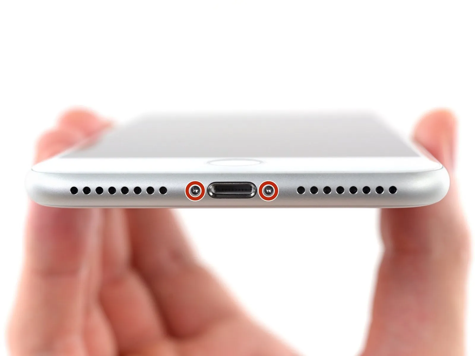
- As a preliminary precaution, ensure your iPhone's battery is depleted to a level below 25% prior to commencing the repair process.A fully charged lithium-ion batteryposes a risk of ignition and/or detonation if it sustains accidental physical damage, such as a puncture.
- Deactivate your iPhone by powering it down completely before you start disassembling it.
- Using a suitable tool, extract the pair of 3.5 mm pentalobe screws located along the iPhone's lower edge.
- Separating the iPhone’s display assembly will damage the integrated waterproof barriers; therefore, obtain replacement seals beforehand to continue beyond this point, or exercise extreme caution to prevent moisture ingress if you intend to reassemble the iPhone without new seals.
Step 2 | Mark your opening picks


- To avoid potential harm to your device, ensure the opening pick does not penetrate excessively; this procedure details how to identify the safe insertion depth by marking the pick.
- Determine the distance of3 mmfrom the pick's leading edge, then use a permanent marker to create a visible indicator on the opening pick.
- For enhanced precision, consider applying distinct markings at various points along the pick's edges, each representing a different measurement.
- As another method, affix a coin to the pick's shaft,3 mmaway from its point.
Step 3 | Tape over any cracks
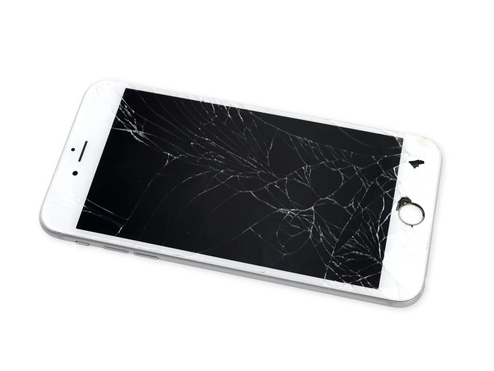
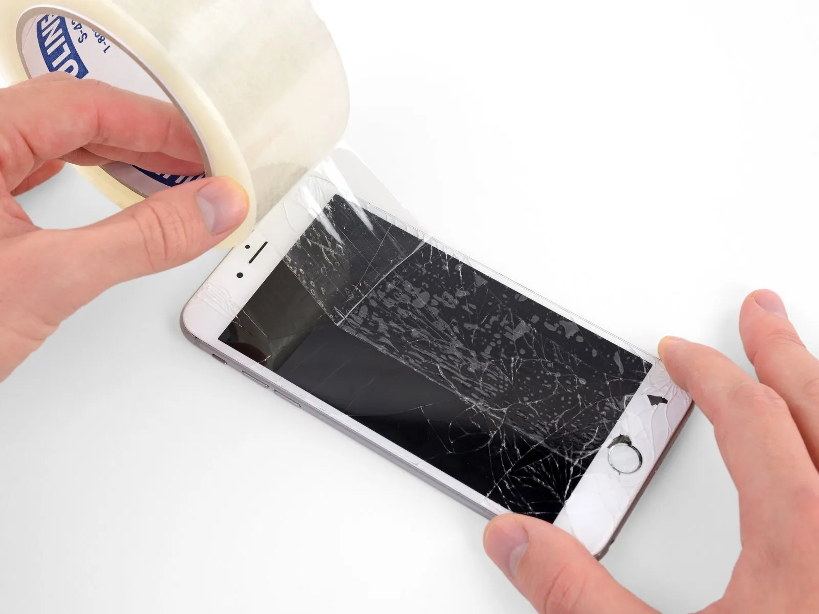

- To mitigate additional damage and potential injury when addressing a cracked iPhone screen, secure the fractured glass with adhesive tape.
- Apply multiple, overlapping layers of transparent packing tape across the entire iPhone screen surface.
- Always utilize eye protection, specifically safety glasses, to guard against glass fragments that may become dislodged during the repair process.
- Should the suction cup fail to maintain adhesion during subsequent steps, create a handle from a robust tape, like duct tape, and employ it to gently elevate the screen.
- As a last resort, secure the suction cup directly to the screen's surface using superglue.
Step 4 | Anti-Clamp instructions


- The following three actions illustrate the function of the Anti-Clamp, a specialized tool developed to simplify the initial opening process; if this tool is not available, proceed to the subsequent three steps for an alternative approach.
- Detailed instructions regarding the Anti-Clamp's operation are available in a separate, dedicated guide.
- Grasp theblue handleand move it in a rearward direction to disengage the Anti-Clamp's securing arms.
- Carefully position the arms across either the left or right side of your iPhone's frame.
- Place the suction cups close to the lower edge of the iPhone, situated directly above the home button—one on the front surface and one on the rear surface.
- Apply pressure by compressing the cups together to establish a secure suction hold on the intended area.
- Should the iPhone's surface prove excessively slick, preventing the Anti-Clamp from maintaining a firm grip, applying adhesive tape can generate a more textured surface for improved adhesion.
Step 5


- To secure the arms, advance the blue handle in its direction.
- Rotate the handle a full 360 degrees, or continue until you observe the cups beginning to deform.
- Maintain the precise alignment of the suction cups; should they become misaligned, marginally reduce the suction cup's tightness and reposition the arms.
Step 6


- Position the iOpener so that it rests along the lower edge of the iPhone’s frame.
- Allow a period of one minute to elapse, enabling the adhesive to soften and facilitating a separation.
- Once the Anti-Clamp has generated a substantial opening, carefully slide an opening pick beneath the display screen.
- Should the Anti-Clamp fail to produce an adequate separation, increase the heat applied to the area and rotate the handle by 90 degrees.
- Avoid rotating the handle beyond a 90-degree increment at any point, and allow one minute to pass between each rotation; rely on the Anti-Clamp and time to achieve the desired effect.
Step 7

- Applying heat to the iPhone's bottom border will assist in loosening the adhesive that holds the screen in place, facilitating easier separation.
- Employ a hairdryer, or alternatively, prepare aniOpenerand direct it towards the iPhone's lower edge for approximately 90 seconds to reduce the adhesive's tackiness.
Step 8


- Ensure the suction cup's surface area remains clear of the home button's location to guarantee a complete and effective bond between the suction device and the glass.
Step 9


- Introduce an opening tool, or a similarly slender prying implement, into the created space, inserting it only a few millimeters.
Step 10


- Cease movement in the vicinity of the display's upper left corner.
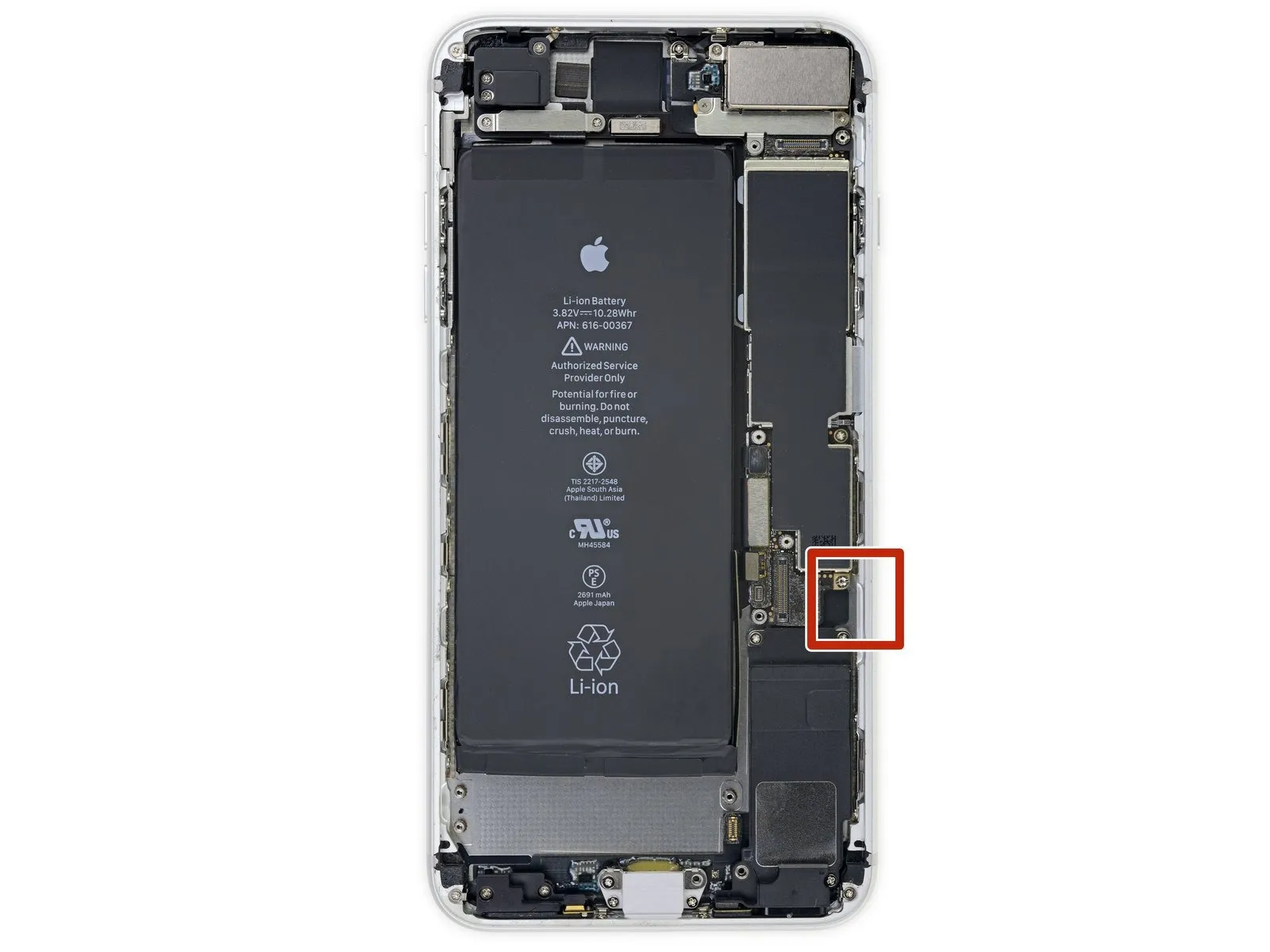
Step 11 | Screen information
Step 12


- Ensure the tool's insertion depth remains under 3 millimeters to prevent potential harm to the display cable connections.
Step 13
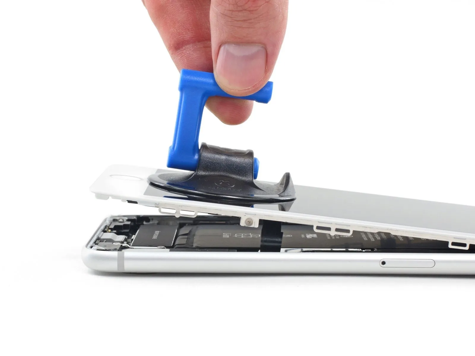
- Carefully elevate the display's lower boundary by applying upward force to the suction cup.
- Avoid lifting the display beyond an angle of15 degreesas exceeding this limit could potentially damage or sever the flexible cable assemblies that interface with the display.
Step 14
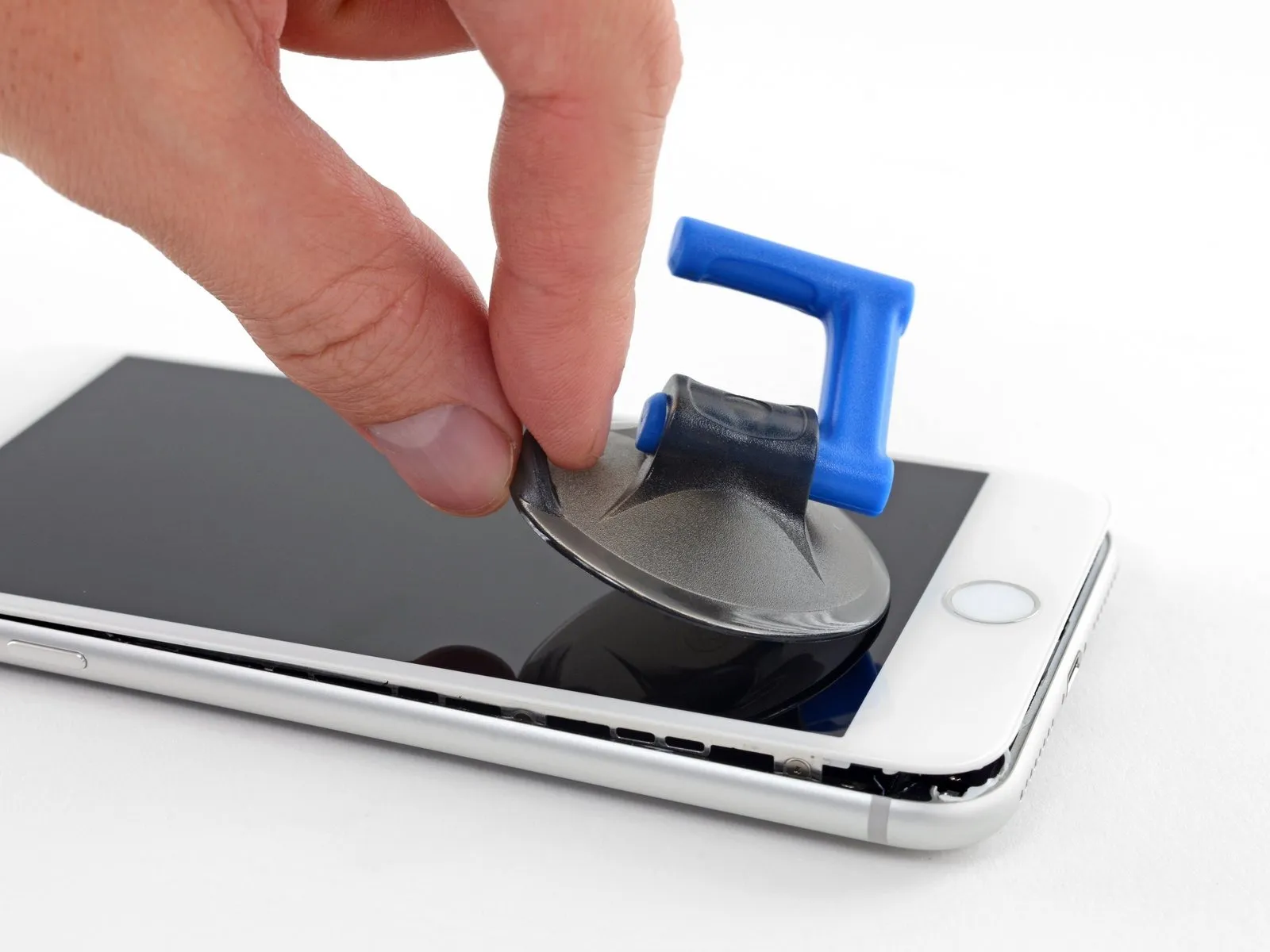
- To detach the suction cup from the front panel, grasp and exert force on the small projection located on its surface.
Step 15
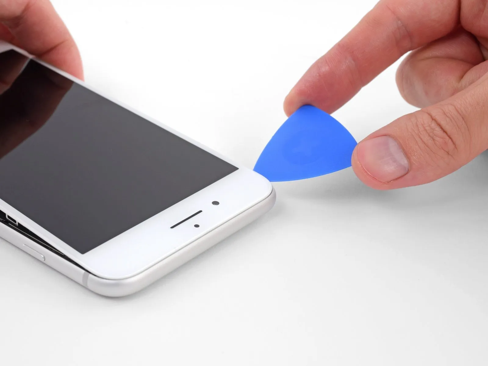


- Carefully insert a separation tool beneath the screen's upper edge, working along the top to release the remaining adhesive bond.
Step 16


- To release the retaining clips securing the display assembly to the rear case, carefully move the display downwards, shifting it away from the phone's upper border.
Step 17
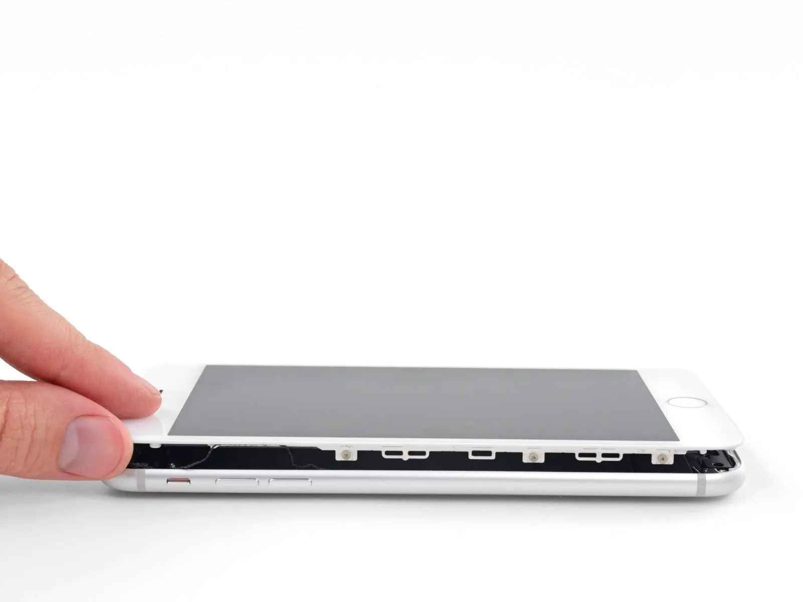


To access the iPhone's internal components, initiate the opening process by pivoting the display upwards, originating from the left edge, mimicking the action of opening a book's cover.
Refrain from completely disconnecting the display assembly at this stage, because multiple delicate ribbon cables remain attached, linking it to the iPhone's main circuit board.
Secure the display in an upright position using a support to prevent it from obstructing your work area during the repair procedure.
Step 18 | Battery Disconnection
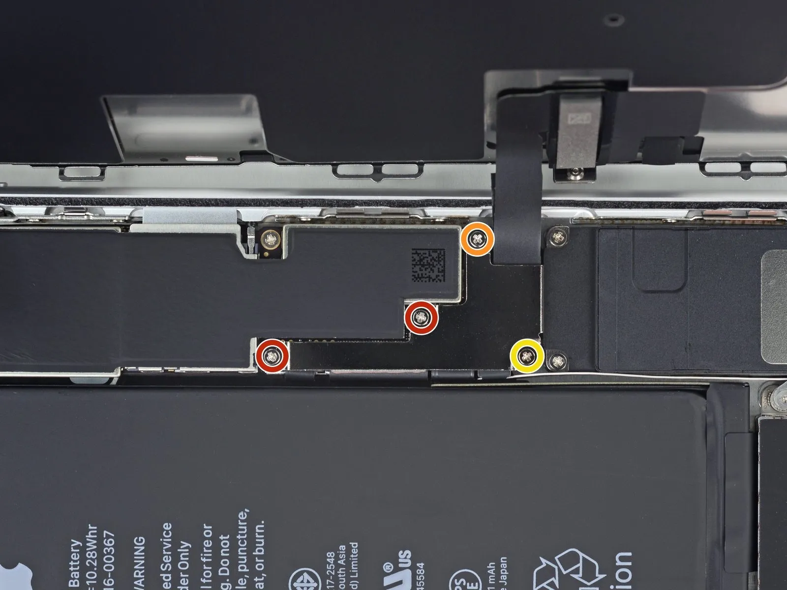

- Detach the four screws that hold the lower display cable bracket in place on the logic board.These screws utilize a Phillips (JIS) head.The screws vary in length, as detailed below:
- Two screws measure1.3 mmin length.
- A single screw is1.4 mmlong.
- Additionally, one screw has a length of2.7 mm.During the repair process, meticulously organize all screws to ensure correct placement during reassembly; improper screw installation can result in irreversible component failure.
Maintaining screw organization is vital to prevent permanent damage.
Step 19
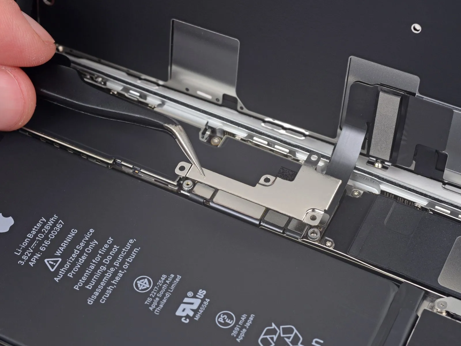
Detach the securing bracket that holds the lower display cable in place.
Step 20
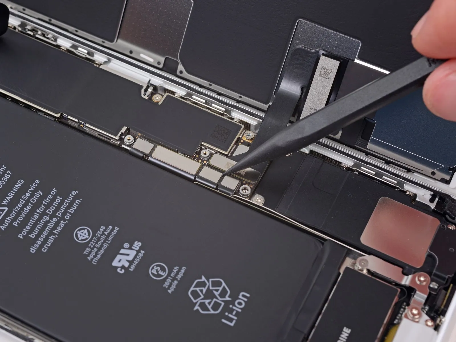

Employ the tip of a spudgerto carefully lift the battery connector away from its corresponding receptacle on the logic board.
Gently elevate the connector cable a small amount to ensure it remains disengaged from the socket, thus avoiding unintended power delivery to the device during the repair process.
Step 21 | Display Assembly
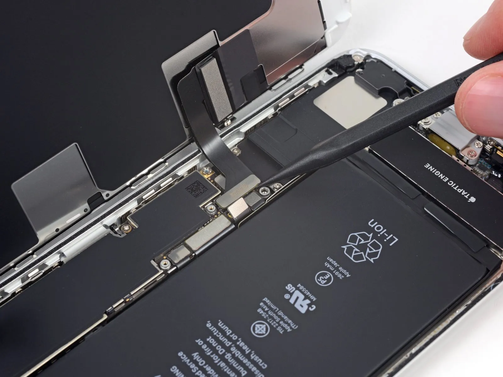

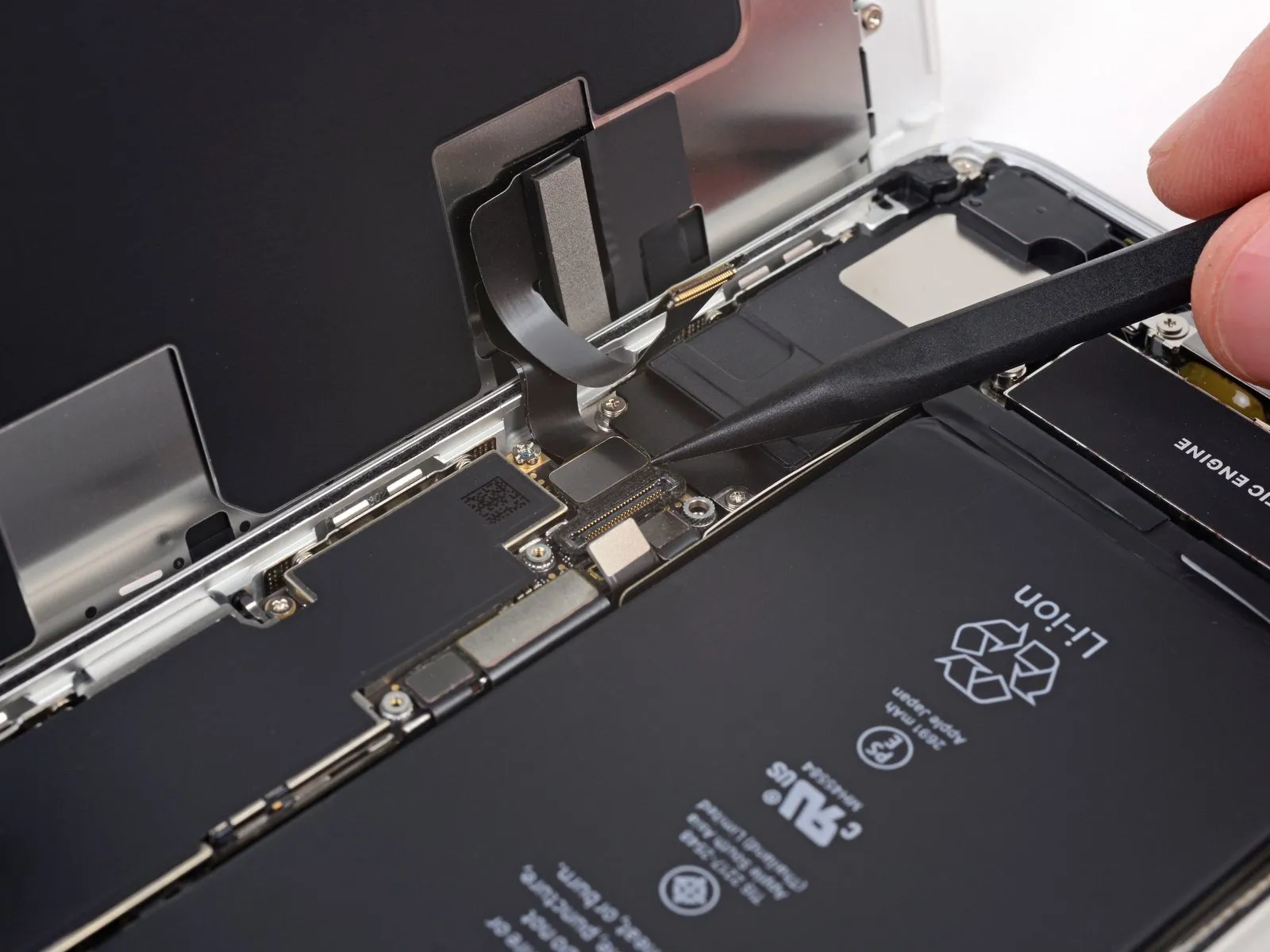
- Employ the pointed end of a spudgeror a fingernailto release the substantial lower display connector, lifting it vertically away from its receptacle.
- When reinstalling connectors, such as this one, apply pressure to one lateral edge until a secure engagement is heard, then repeat the process on the opposing side; avoid applying pressure to the central portion. Even minor connector misalignment can result in bending, potentially leading to irreversible damage.
Step 22

Step 23
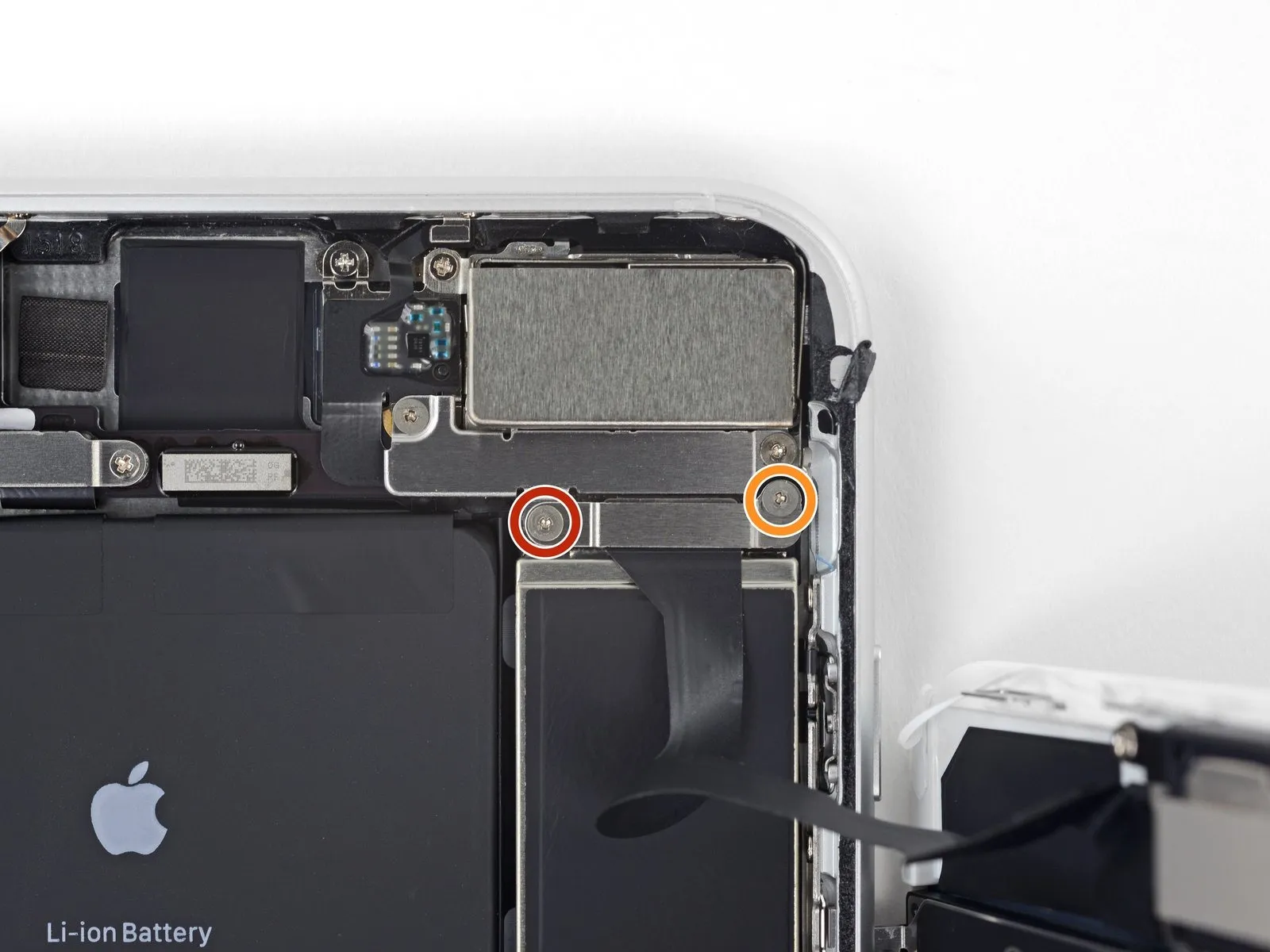

- Detach the pair of screws, utilizing a tri-point tool, that hold the bracket in place, which covers the connector for the front panel sensor assembly.Y000These screws include a 1.0 mm screw and a 1.2 mm screw.
1.0 mm
1.2 mm
Step 24

Step 25

Step 26

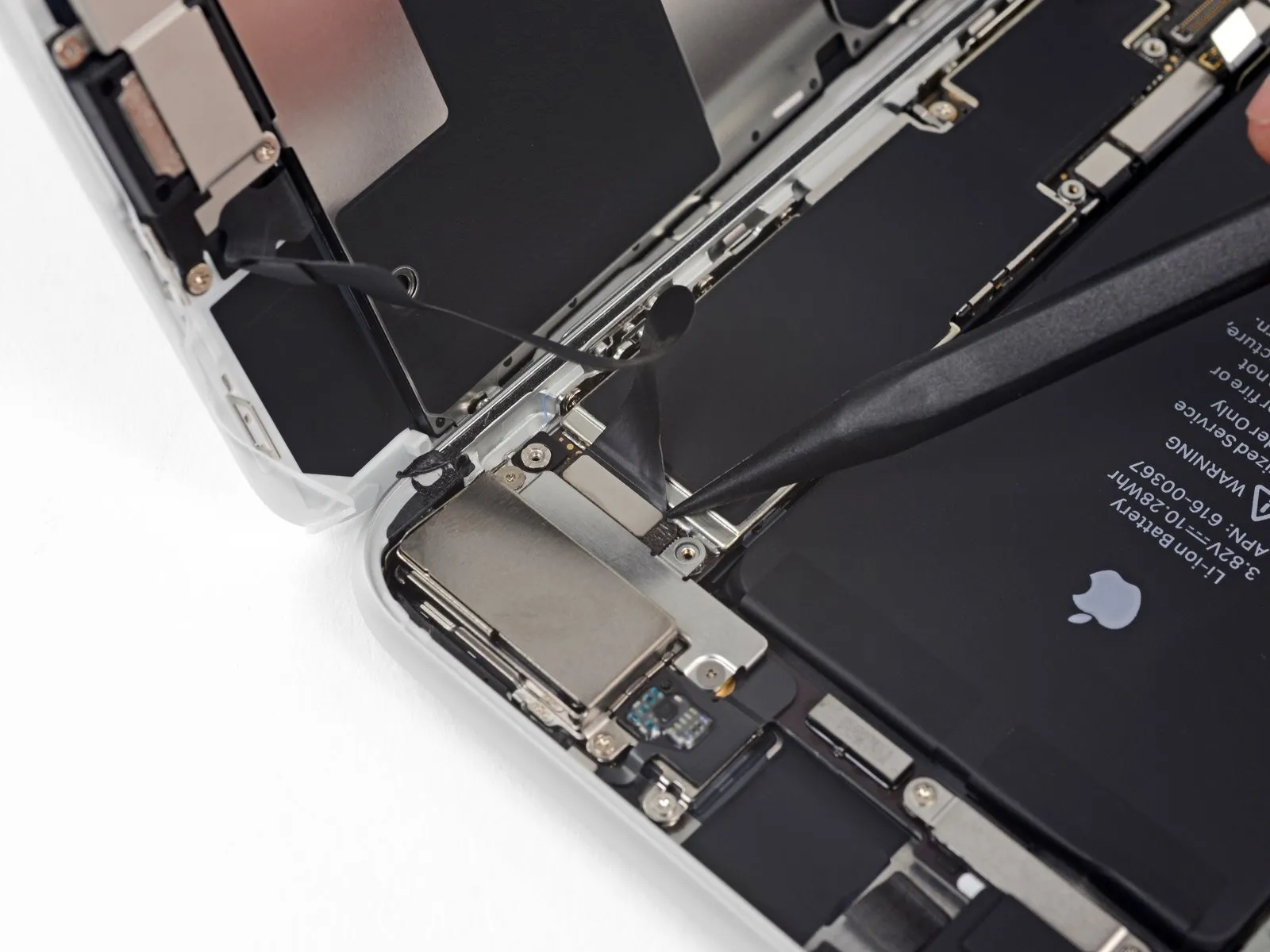
- Detach the display assembly from the device.
- If you intend to substitute the adhesive securing the display's perimeter during reassembly, halt the process at this stage.
Step 27 | Rear-Facing Cameras


- Detach the two fasteners that hold the rear camera connector cover bracket in place.Utilize a Y000 screwdriver to remove these screws.The bracket's purpose is to protect the camera connector.
- A single 1.4-millimeter screw
- along with another 1.4-millimeter (nonferrous) screw
Step 28

- Detach the bracket from its affixed location.
Step 29


- To detach the rear camera module cover plate, first eliminate the two screws that hold it in place.
- A 1.8 mm Phillips screwdriver is required for one of the screws.
- The second screw is a 2.7 mm standoff screw, made of a nonferrous material.
If a standoff screwdriver isn't available, a small flathead screwdriver can be substituted; however, exercise heightened care to prevent slippage and potential harm to surrounding parts.
Step 30

Step 31


Step 32


Should you encounter resistance during separation, reposition to the pointed tip of the spudger and apply leverage from the camera's upper right quadrant.
Step 33

Step 34 | Top Left Antenna

- To detach the upper left antenna assembly, first eliminate the three Phillips head screws that hold it in place.
The fastening process requires two screws, each measuring 1.3 millimeters in diameter. - A single screw, with a diameter of 3.1 millimeters, is also necessary for this procedure.
Step 35

Step 36


A small indentation along the iPhone's upper edge secures the screw boss located on the antenna component.
- Elevate the antenna component, angling it upwards towards the phone's uppermost section.
- Move the screw boss in a downward direction, subsequently disengaging it from its holding space.
Step 37

Step 38 | Wi-Fi Diversity Antenna


- A single Y000 screwdriver bit is required to fasten a 1.3-millimeter screw.
- A Phillips head screwdriver, sized for a 2.6-millimeter screw, is needed.
- Secure a 3.5-millimeter fastener using a Phillips screwdriver.
Step 39

Step 40


Carefully detach the antenna flex cable from the speaker's upper surface utilizing a prying tool, exercising caution to avoid damage.
A minimal adhesive secures this flex cable segment; applying warmth via an iOpener or hairdryer can facilitate separation by softening the adhesive, simplifying the process and allowing for subsequent reattachment without risk.
Step 41


Employ the tip of a spudgerto carefully lift and separate the antenna flex cable from its connection on the logic board.
Step 42


- Employ the tip of your spudgerto carefully lift and detach the antenna flex cable's opposite connector from its receptacle, which is situated adjacent to the Lightning Port.
- Re-establishing the connection of this cable presents a challenge; simplify the process by utilizing tweezers to secure the flex cable, ensuring the connector is properly positioned relative to its socket. Subsequently, apply gentle downward pressure on the connector with the broad side of your spudger until you hear a distinct clicking sound indicating secure engagement.
Step 43

Detach the Wi-Fi diversity antenna from its location.
Step 44 | Taptic Engine
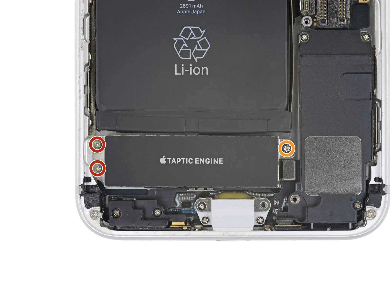
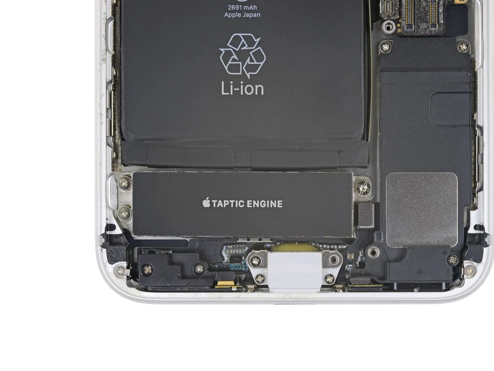
- To detach the Taptic Engine, begin by eliminating the three screws that hold it in place.
- You will need two1.5 mm Phillips head screws for this process.
- Additionally, there is one2.4 mm standoff screw that must be removed.
- For optimal results when removing standoff screws, a standoff screwdriver or a specialized bit is recommended.
- If a standoff screwdriver is unavailable, a small flathead screwdriver can be substituted; however, exercise heightened care to prevent slippage and potential harm to nearby parts.
Step 45
Step 46
Step 47 | SIM Card
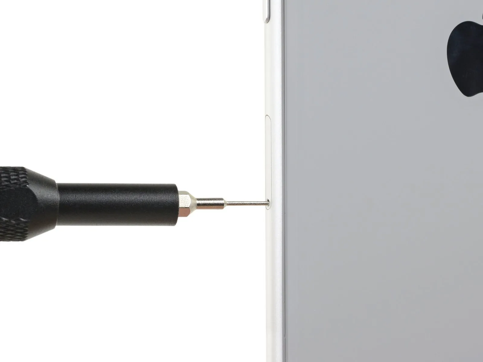


- To release a SIM card, utilize a SIM card eject tool or a straightened paperclip, carefully inserting it into the aperture located on the SIM card tray.
- Apply consistent pressure to the tray to facilitate its complete removal.
Step 48

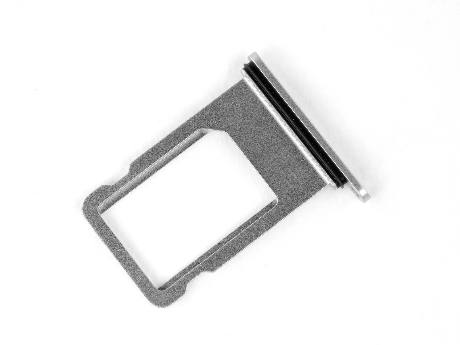
- Extract the SIM card tray from the iPhone's housing.
- The SIM card should detach from the tray with minimal effort.
- During the process of putting the SIM card back into the tray, confirm its correct alignment.
- A flexible, thin seal made of rubber encircles the SIM tray, safeguarding the iPhone's interior from moisture and particulate matter; should this seal become compromised or absent, either substitute the seal or the SIM tray assembly to maintain the iPhone's internal component protection.
Step 49 | Lightning Connector Assembly
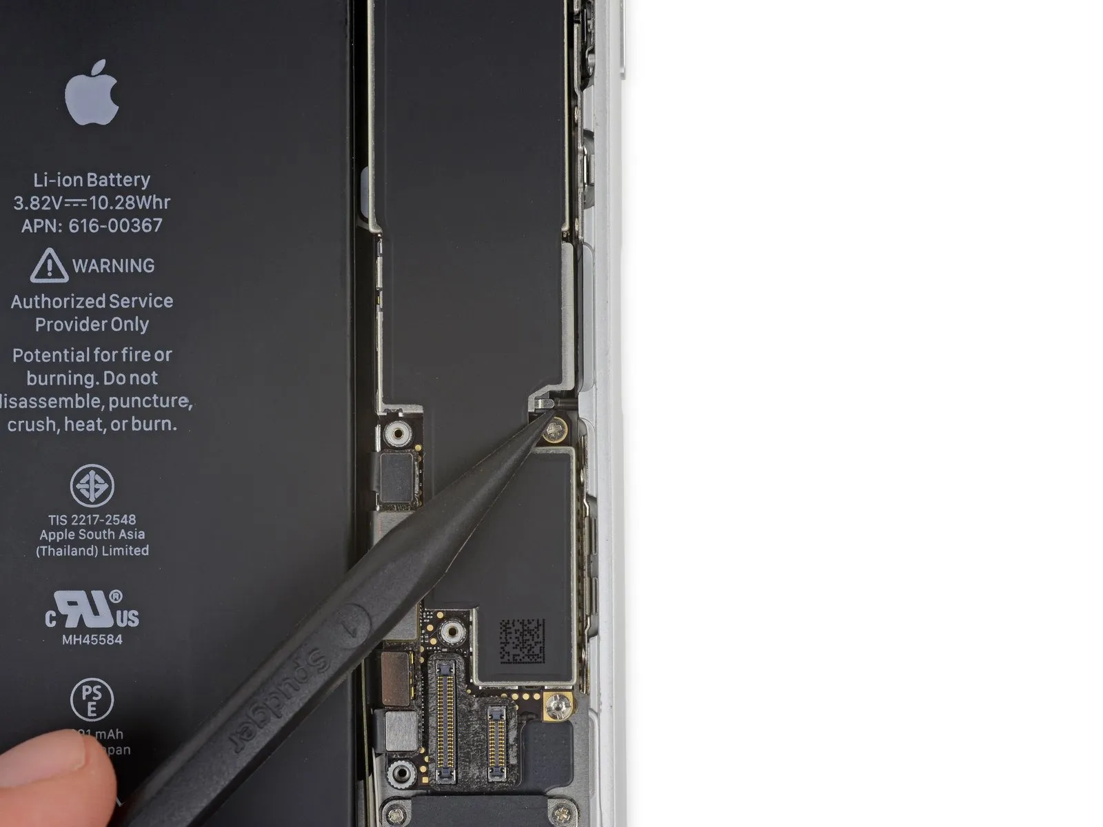
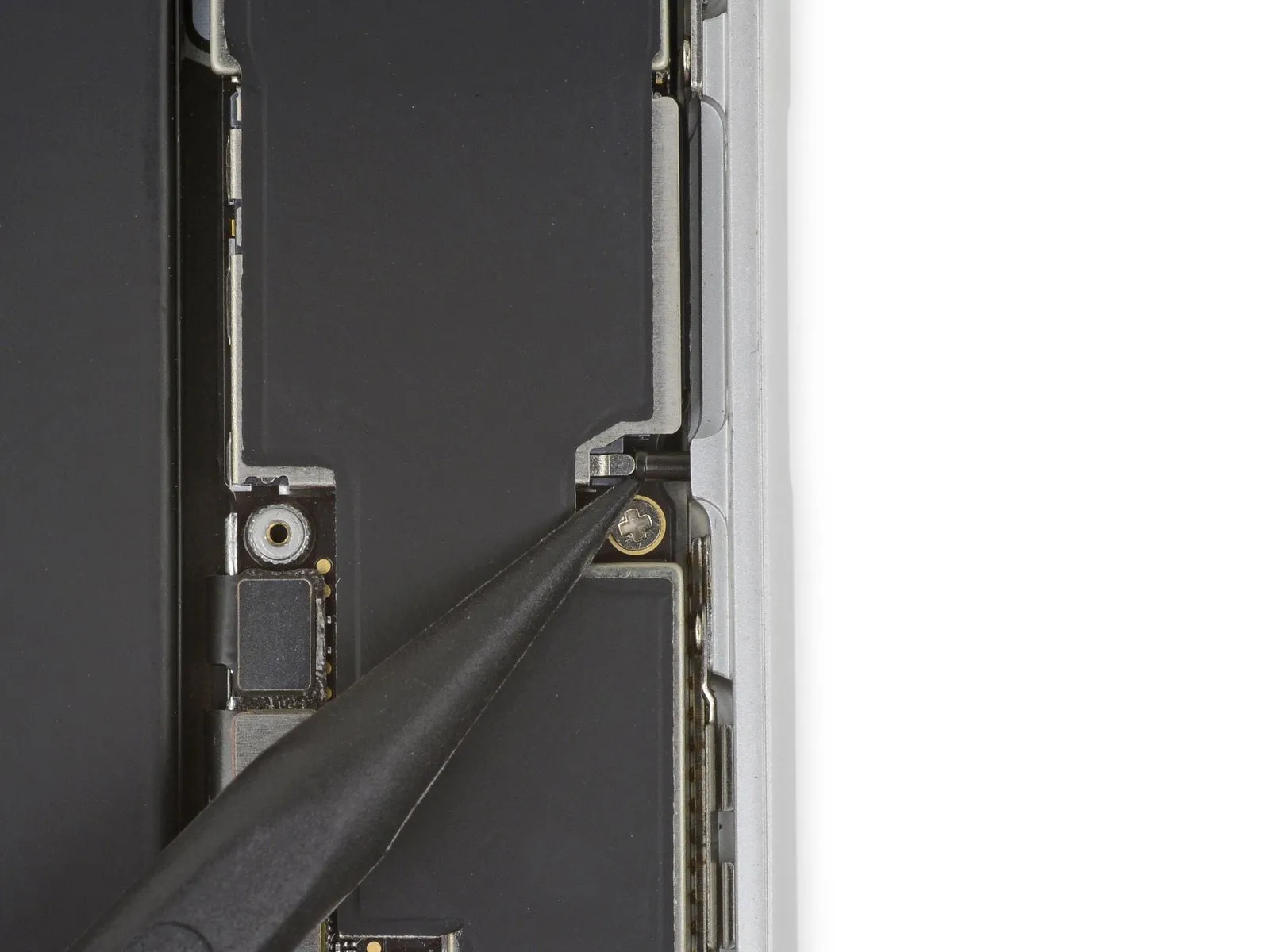
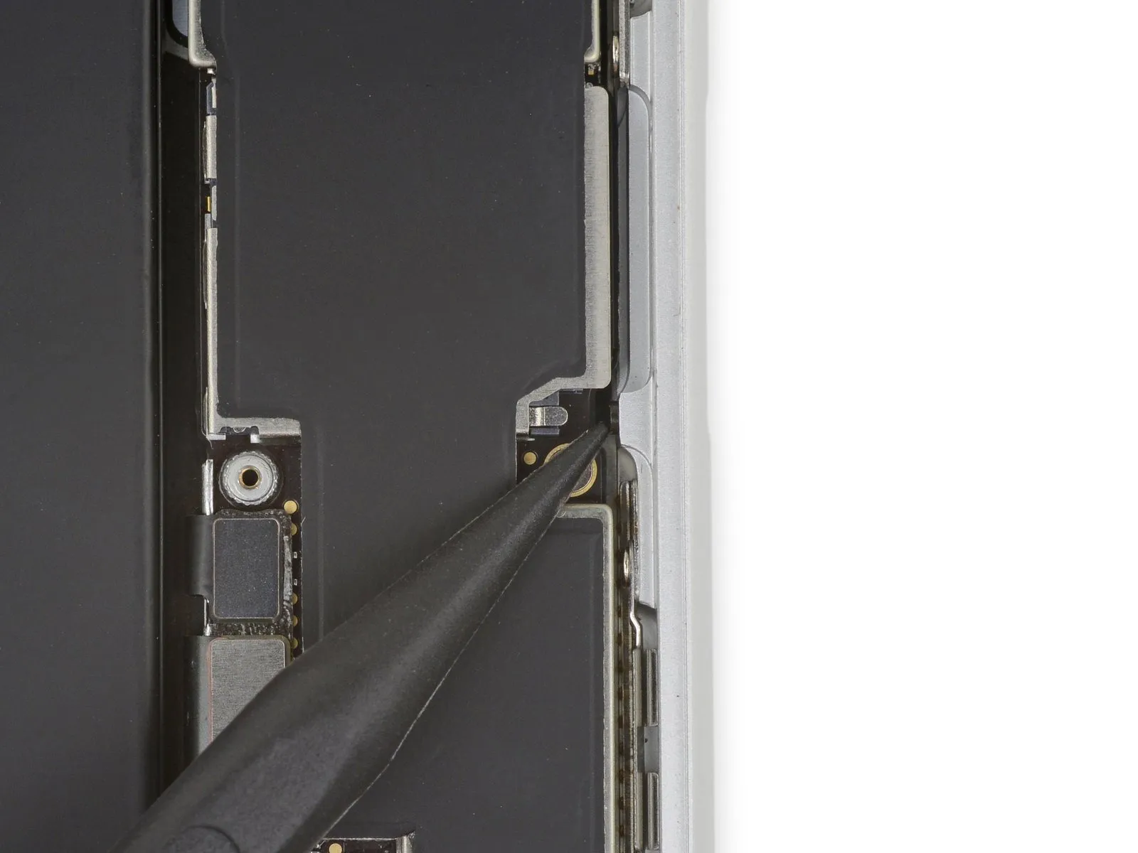
Step 50
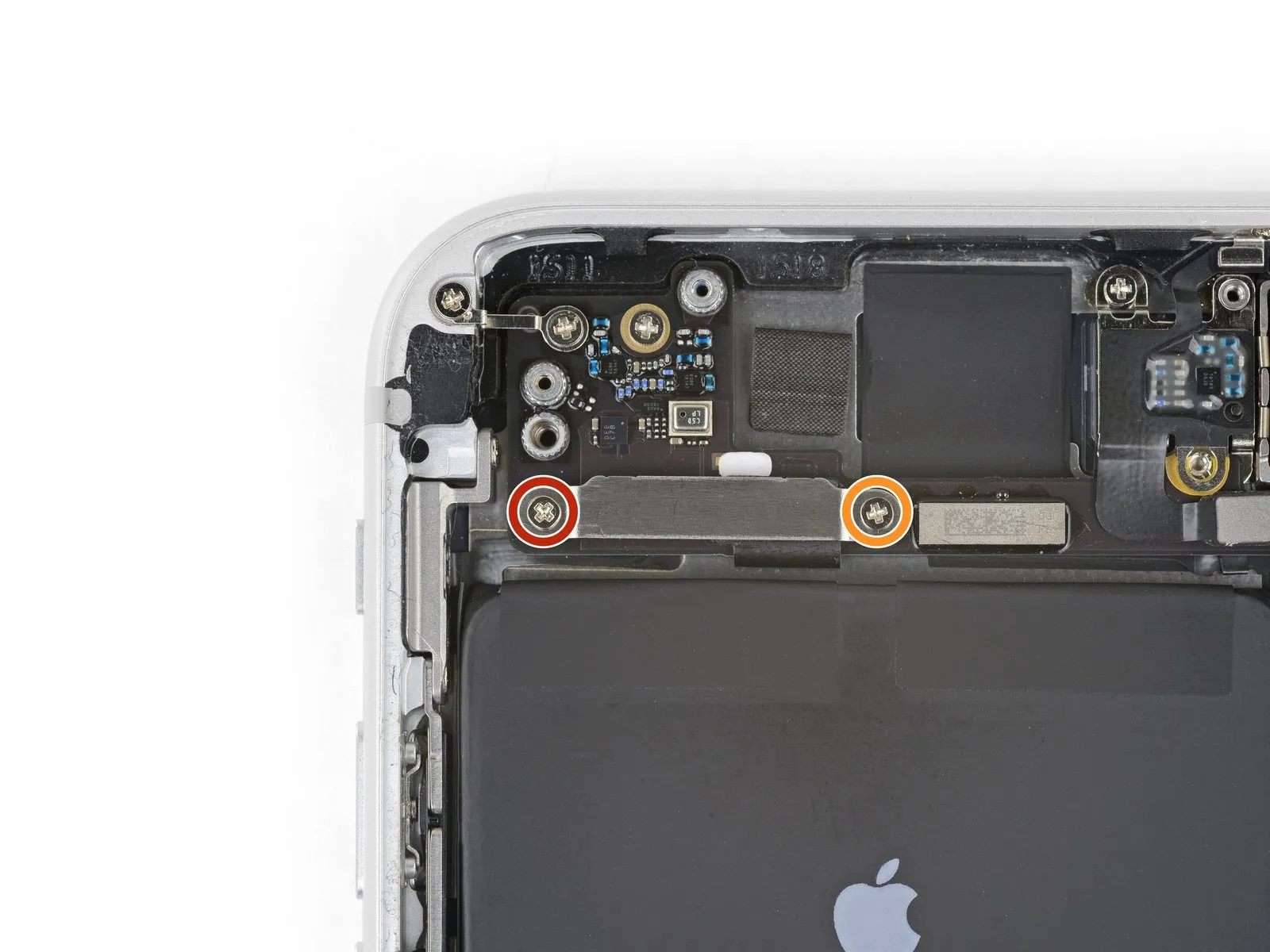
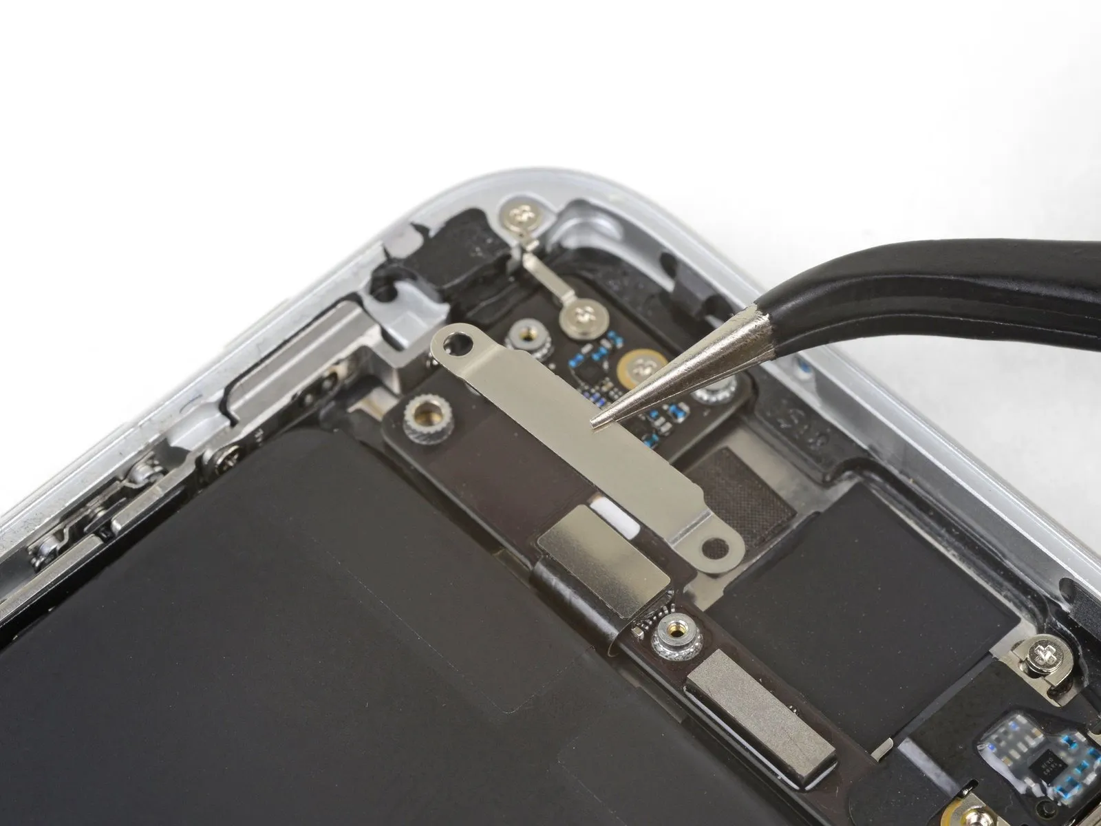
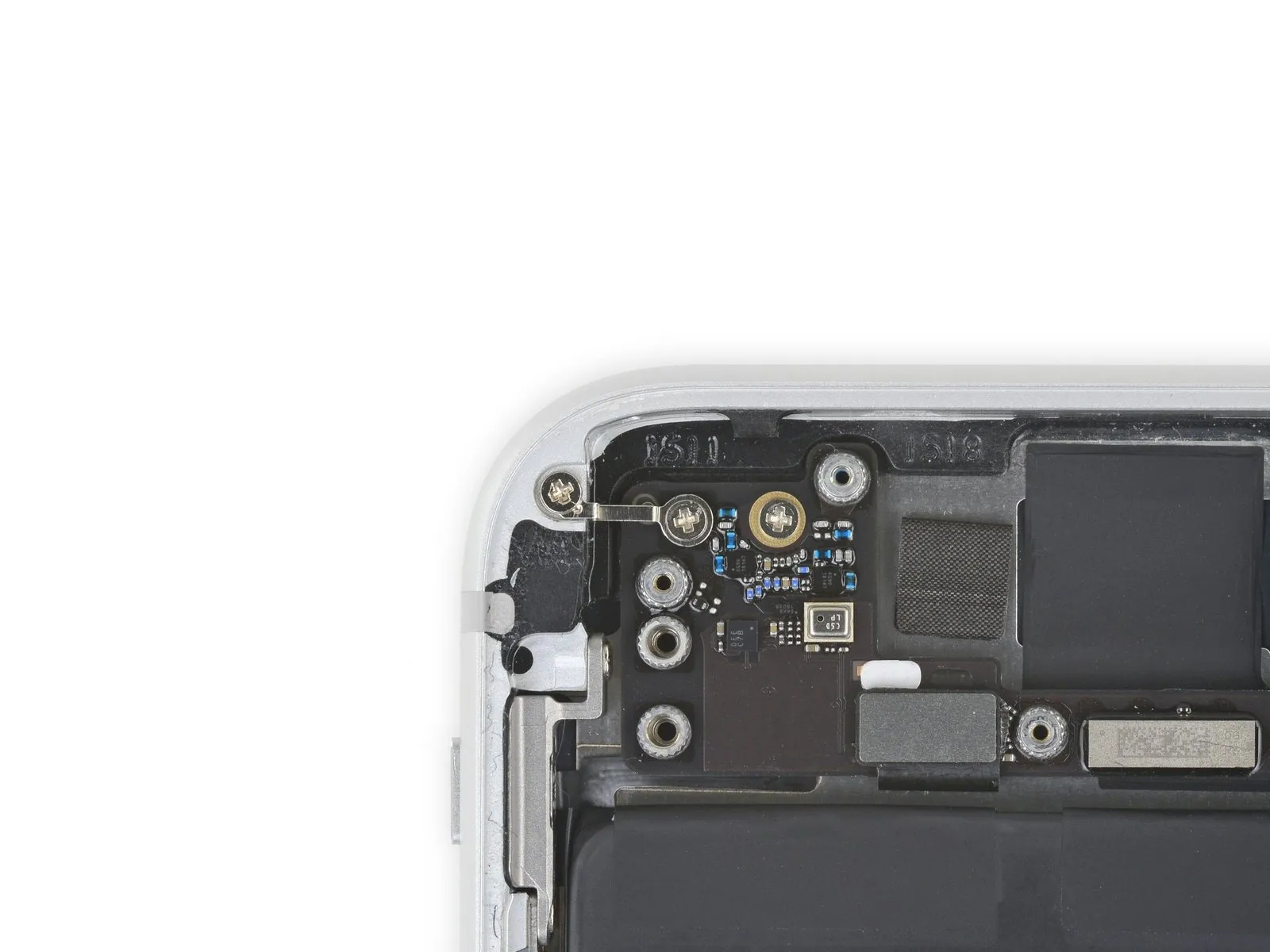
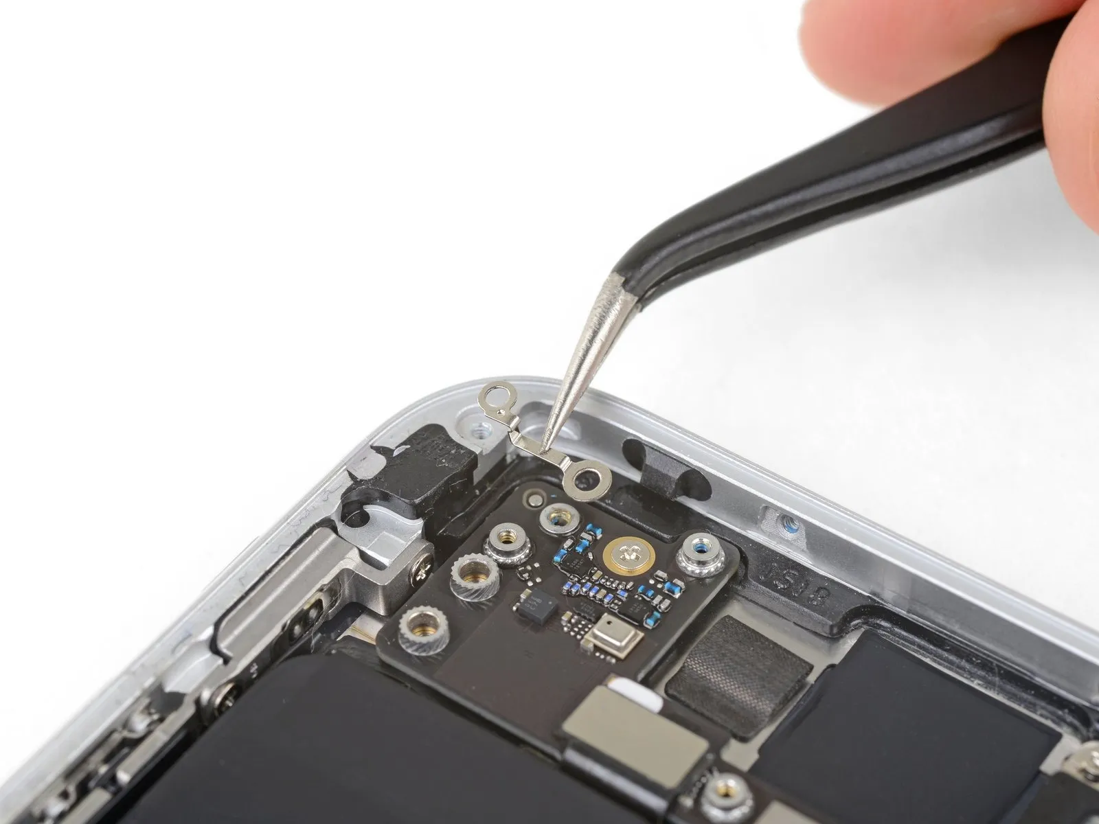
- Detach the bracket that covers the upper cable connector by unscrewing two Phillips head fasteners.
A 3.1 millimeter screw is required.
A 1.3 millimeter screw is also needed.
Ensure the longer screw is positioned on the left-hand side during reassembly.
Step 51
Step 52
Step 53
Step 54
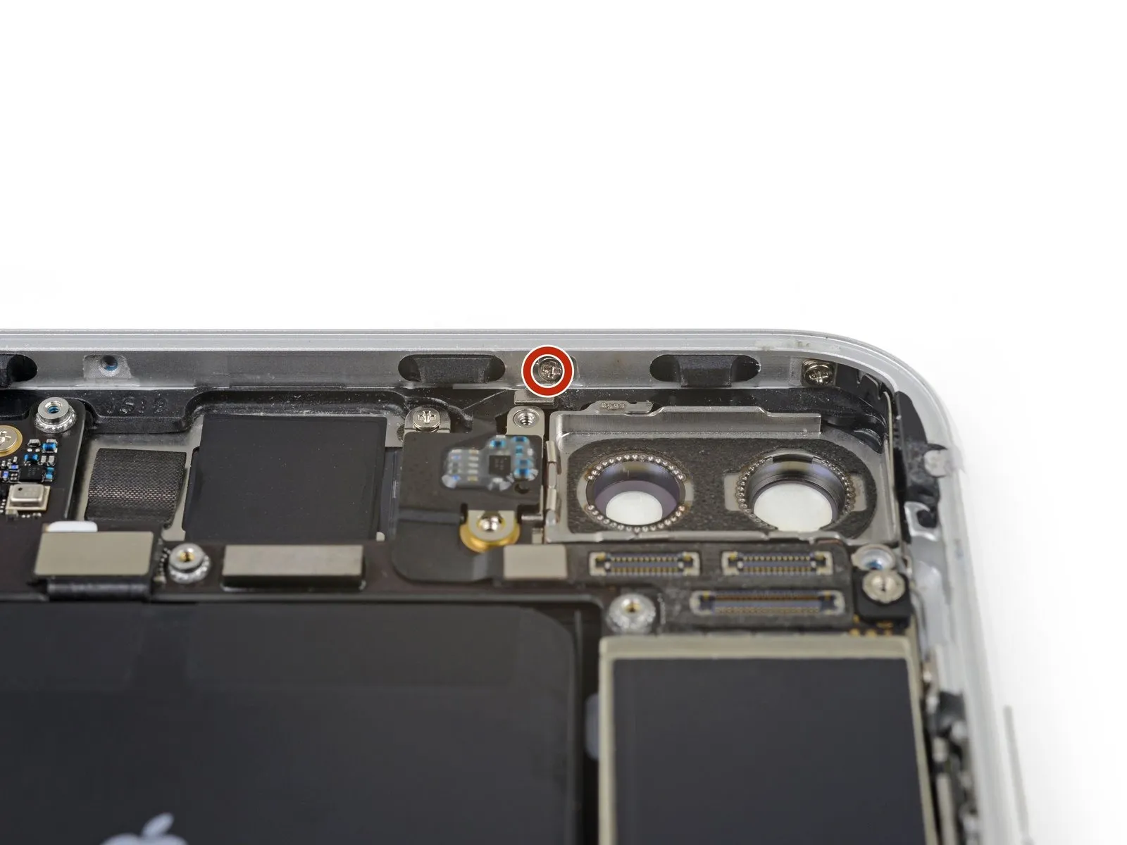
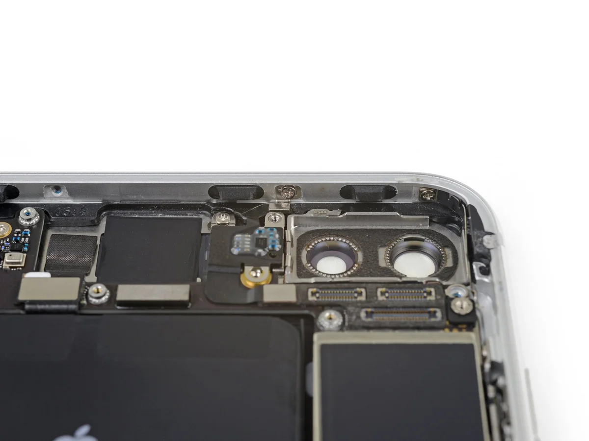
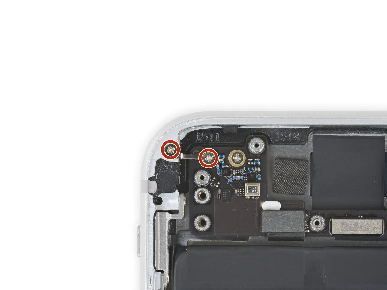
- Detach the1.2-millimeter Phillips screwthat fastens the antenna flex cable to the upper border of the iPhone's back cover.
Step 55
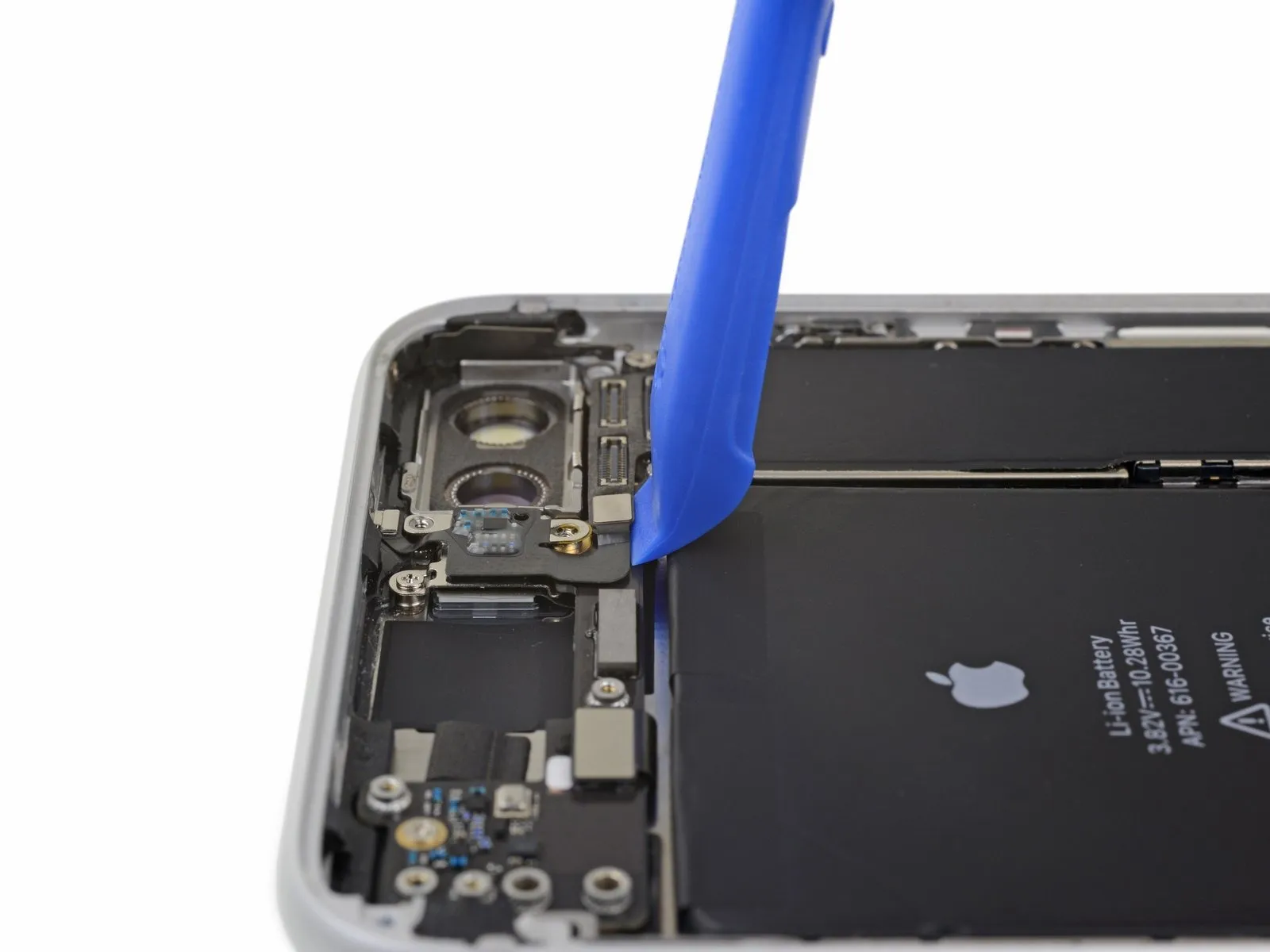
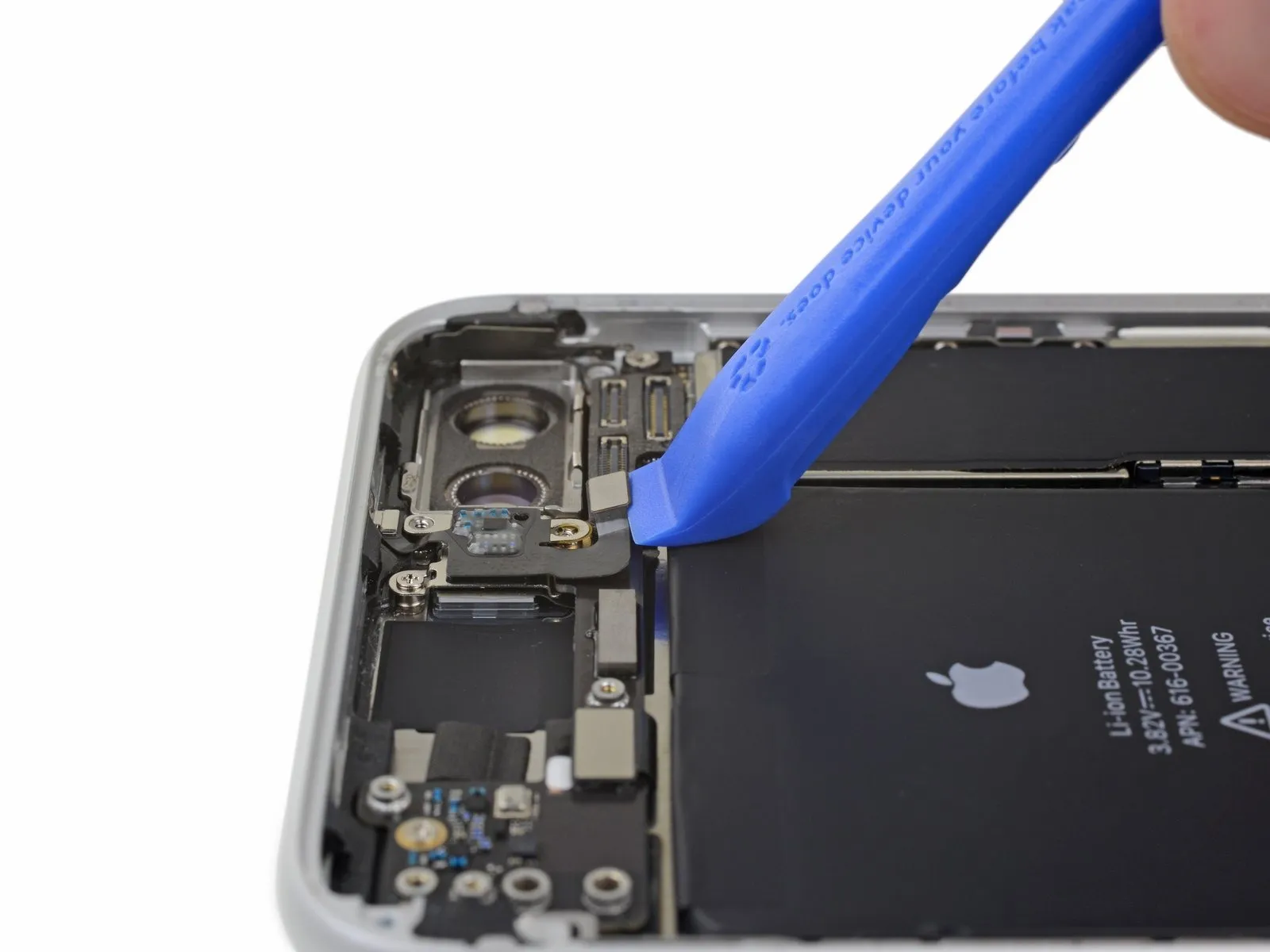
- Employing either a fingernail or the pointed tip of an iFixit opening tool, carefully separate and detach the antenna flex cable connector from the logic board.iFixit opening toolto pry up and disconnect the antenna flex cable connector from the logic board.
Step 56
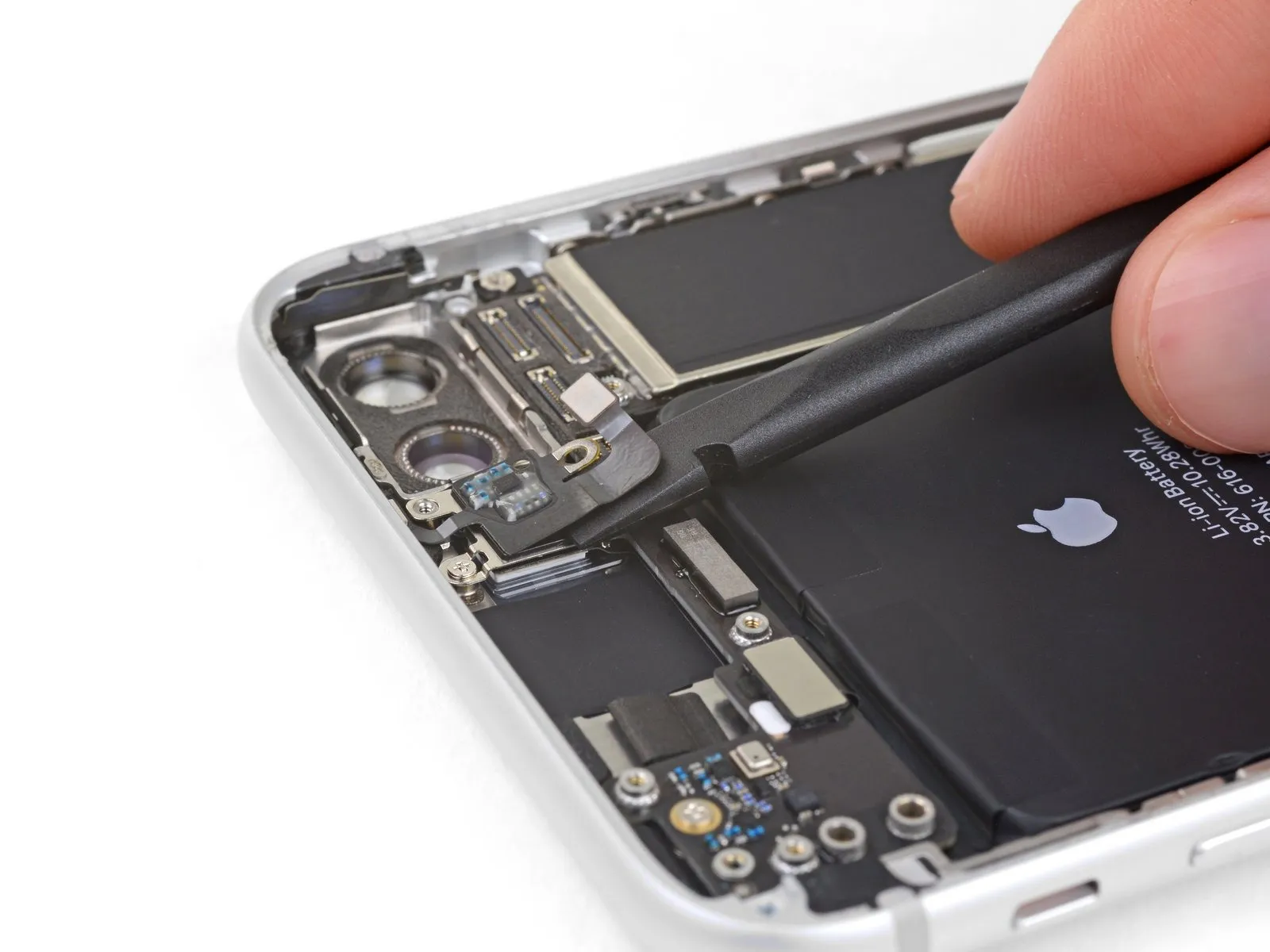
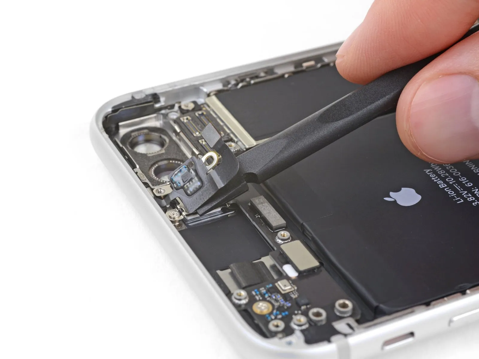
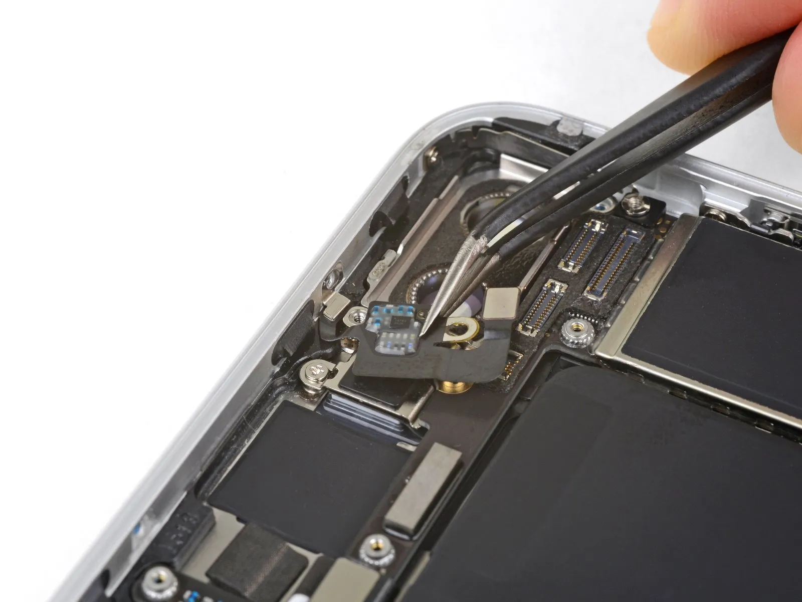
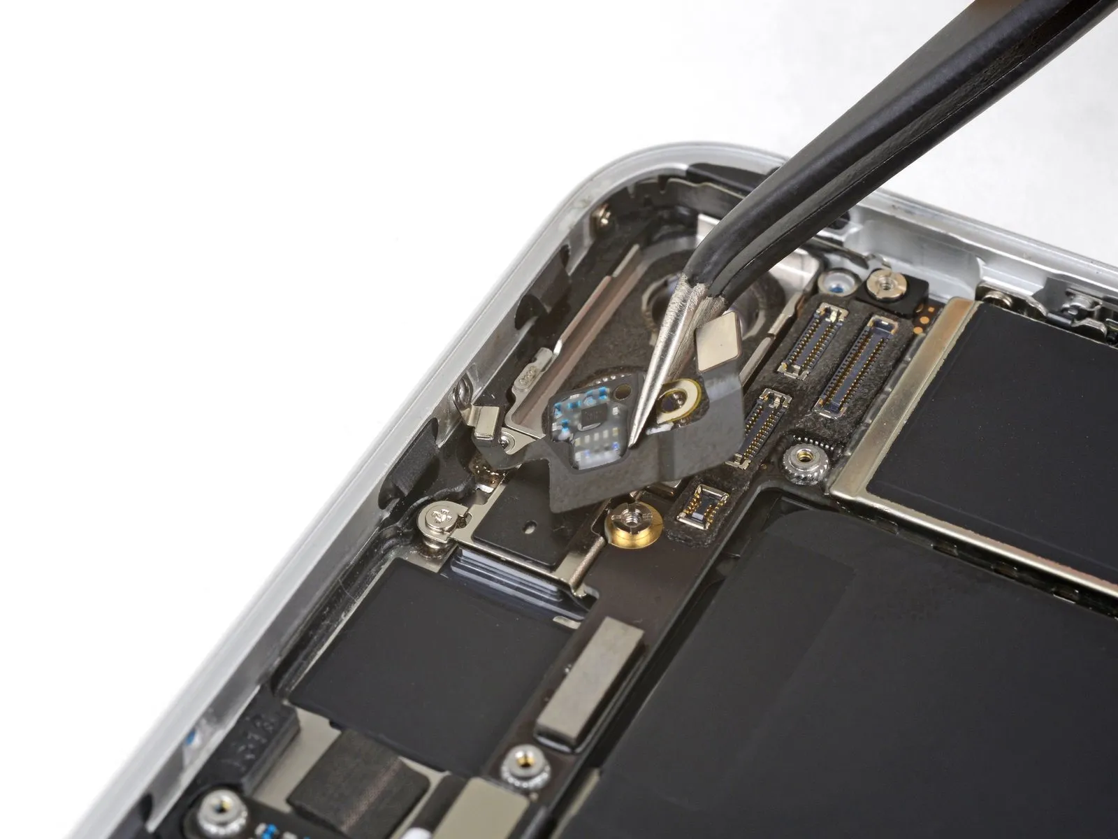
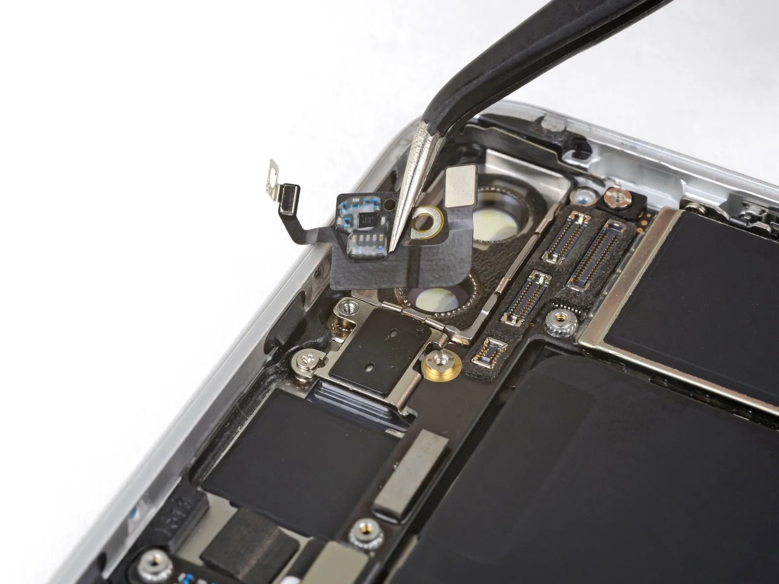
- Utilize the planar edge of a spudger to carefully lift the antenna flex cable, releasing the adhesive securing it.
Step 57
Step 58
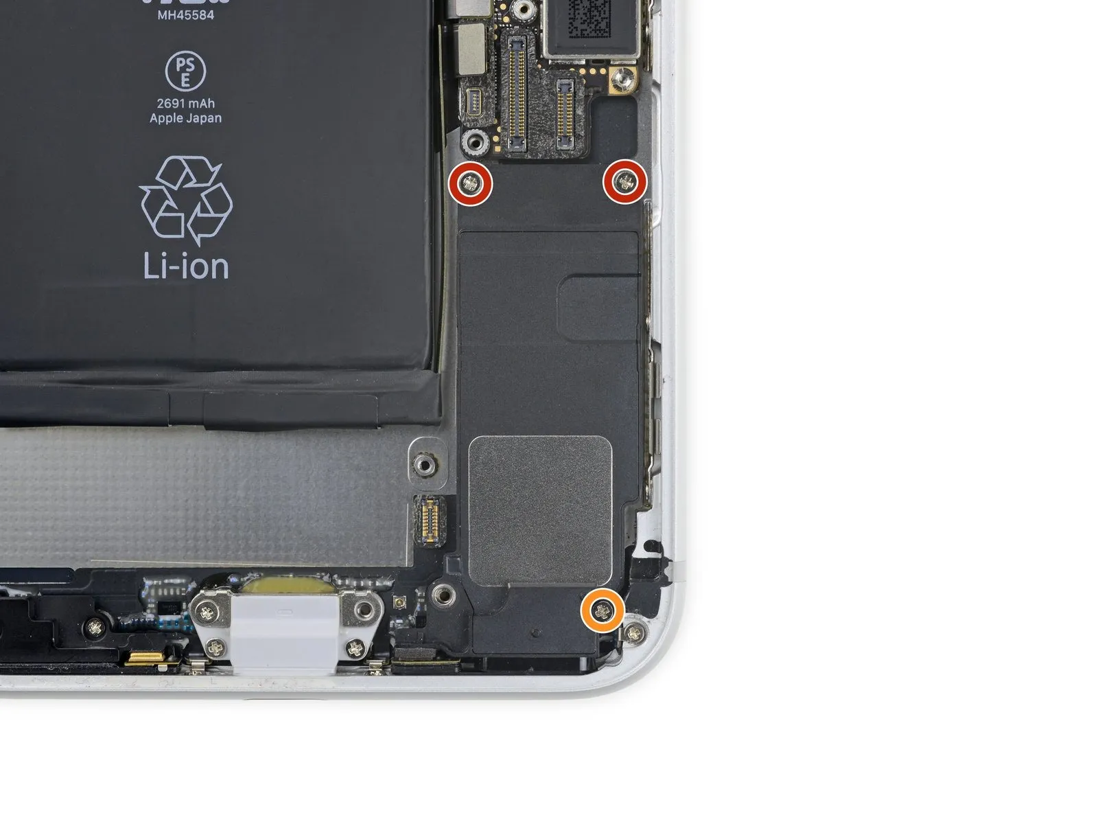
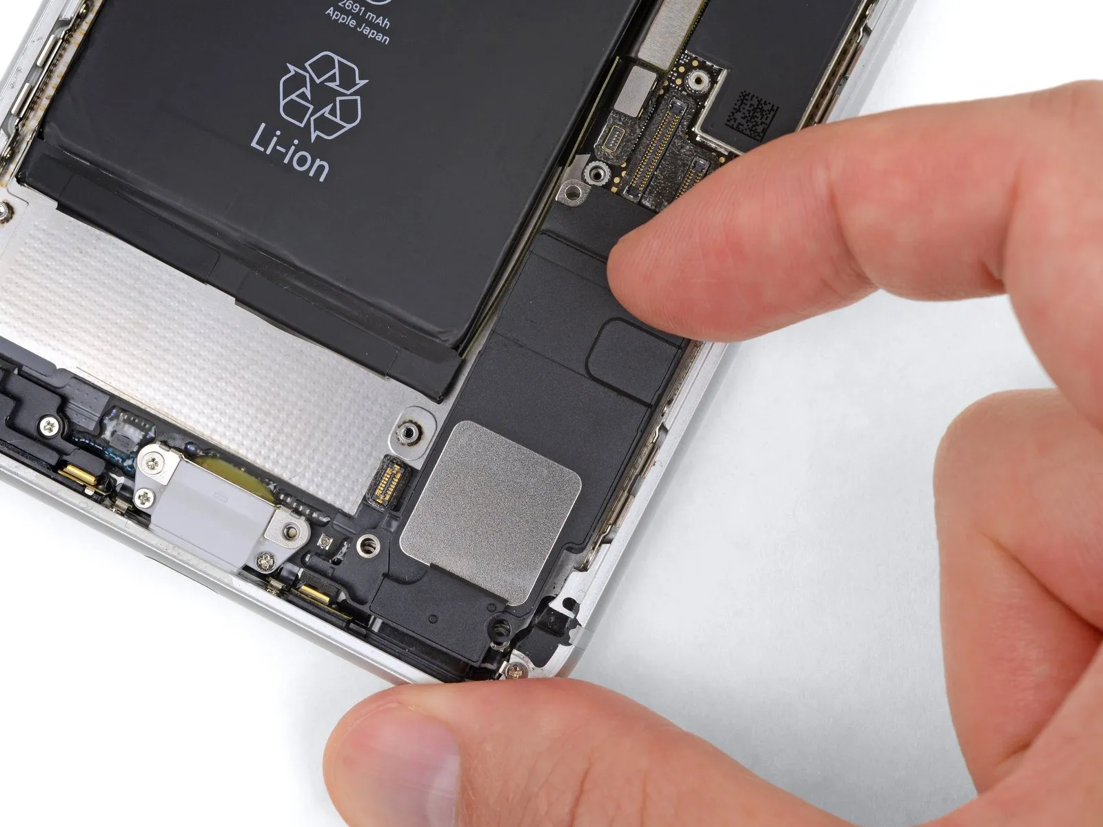
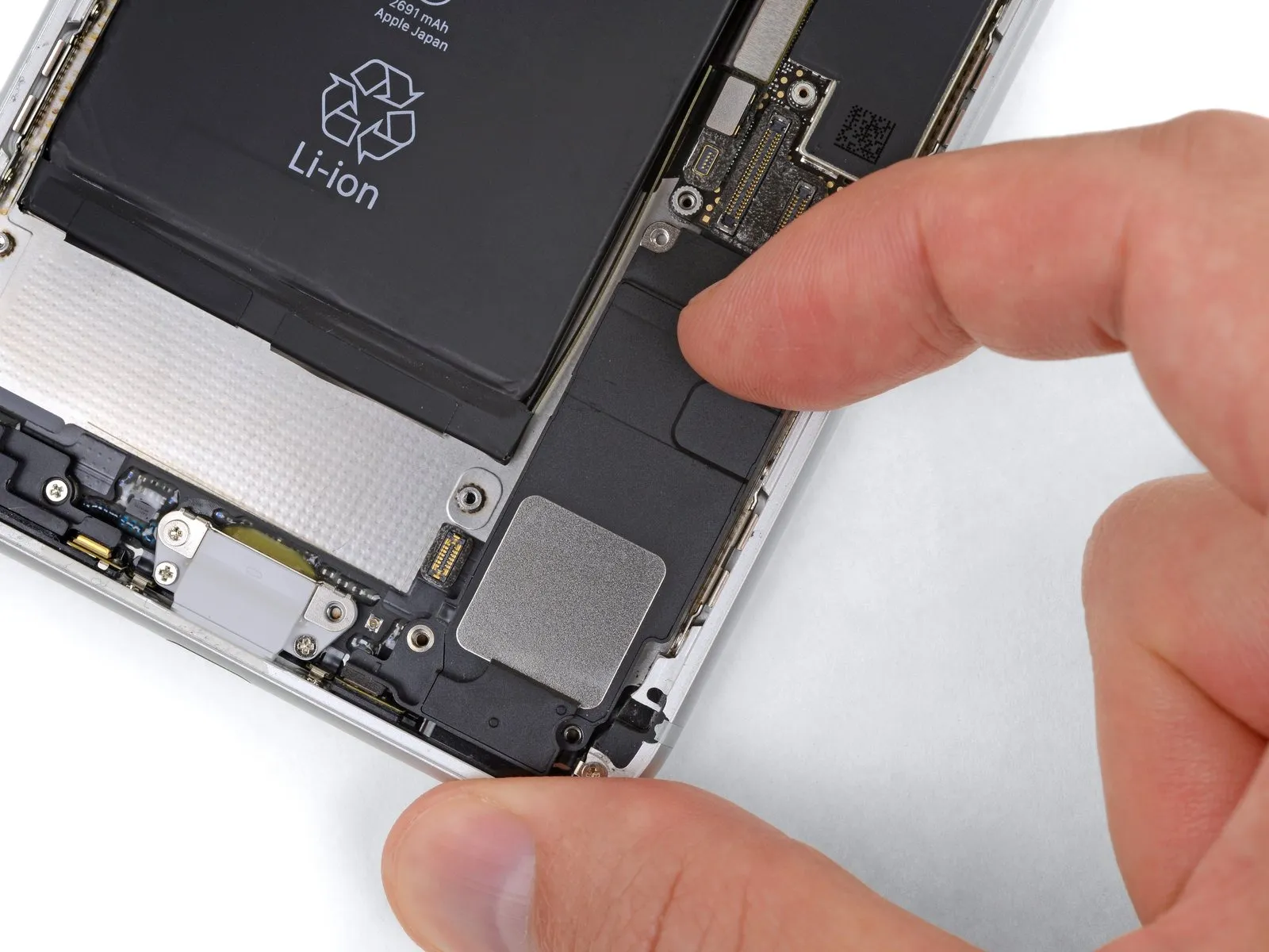
- Two 1.4 mm screws
- One 2.4 mm screw
Step 59
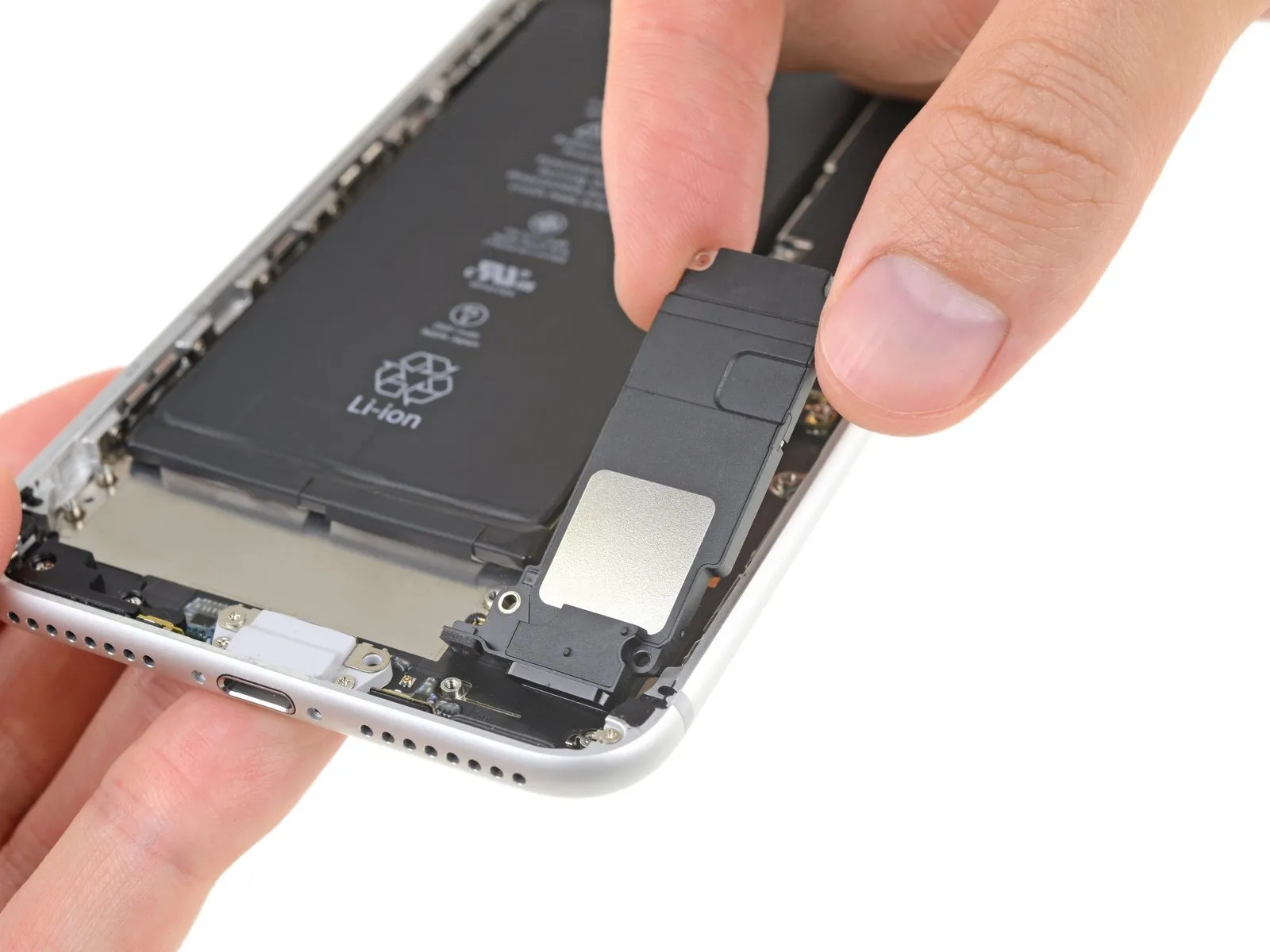
Step 60
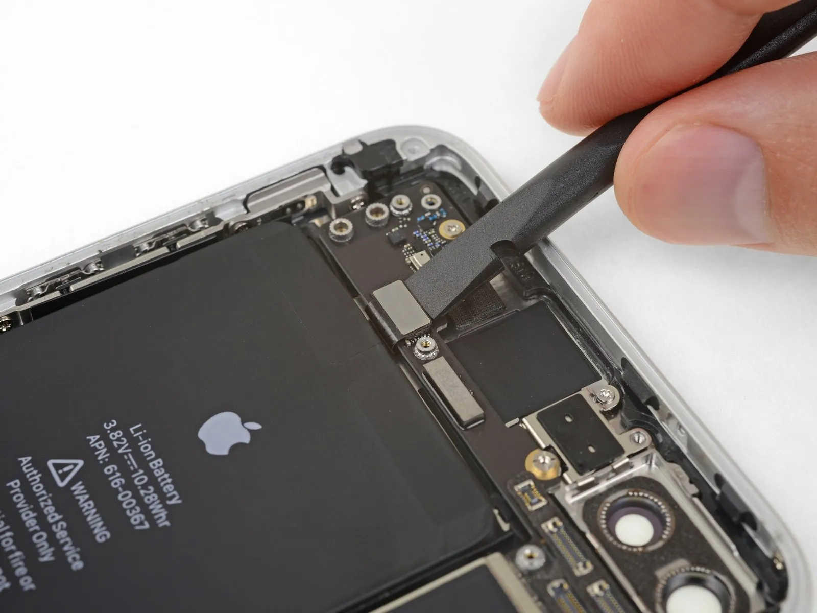
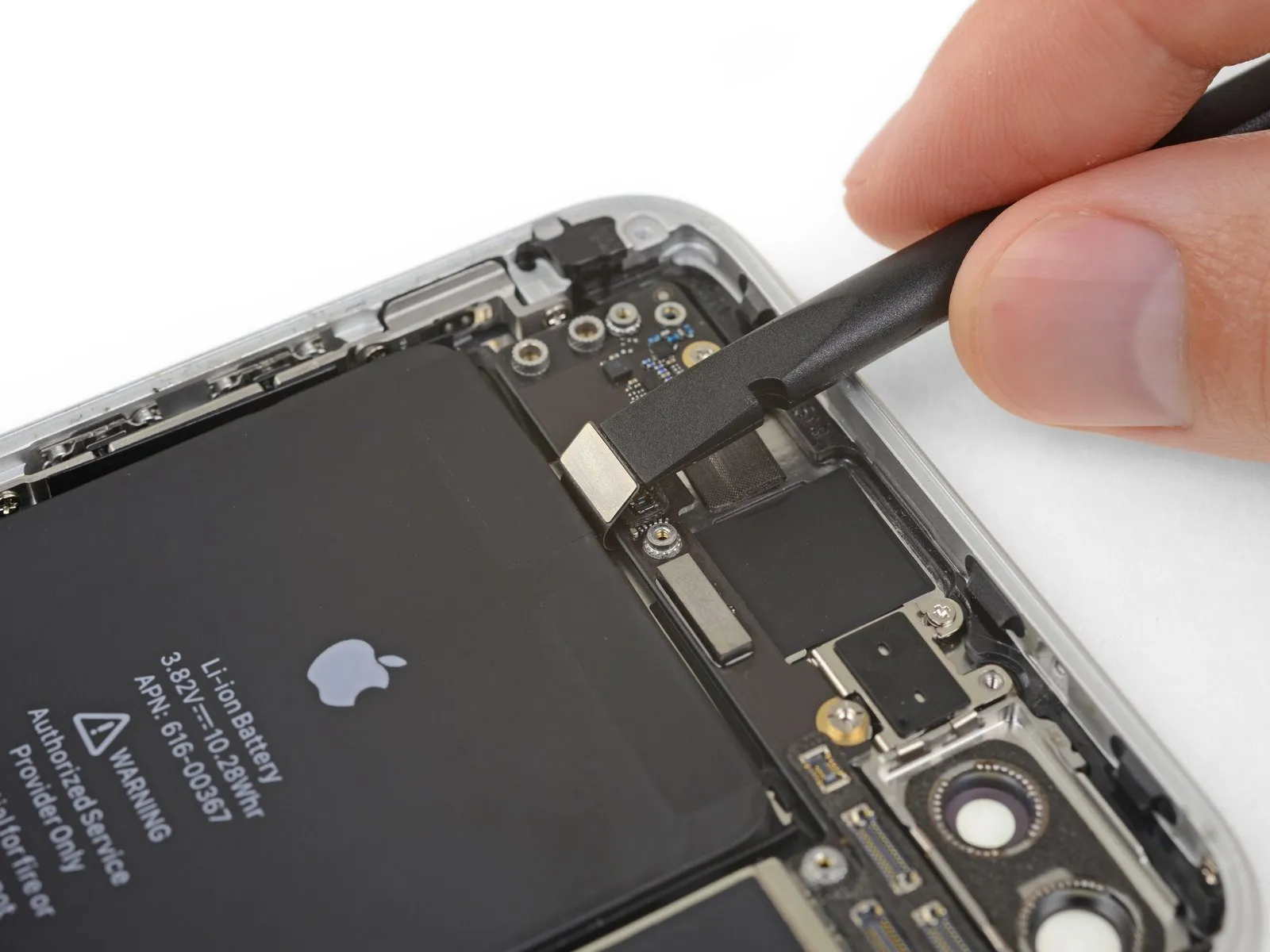
Step 61
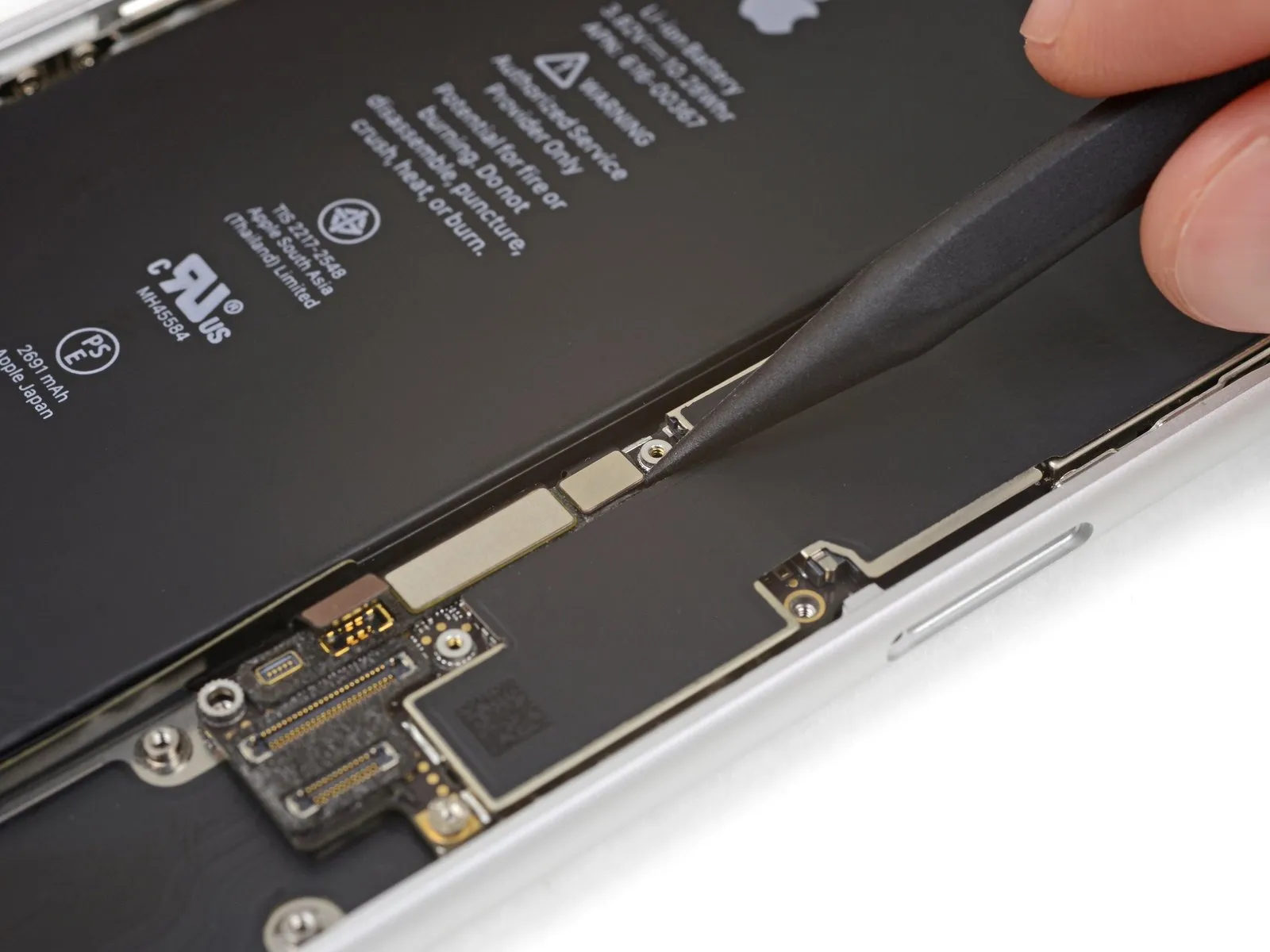
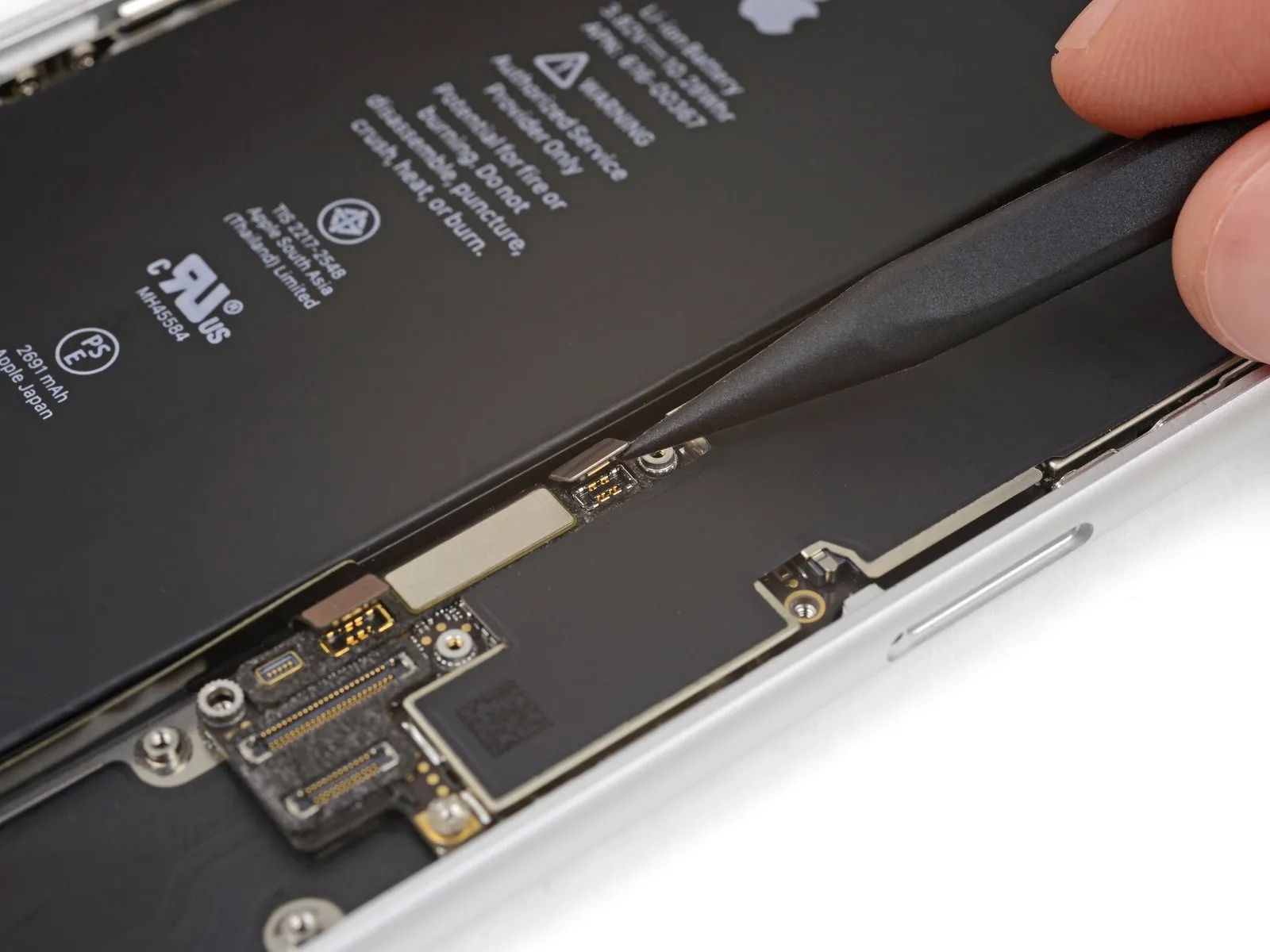
Employ the tip of a spudgerto gently lift and detach the wireless charging coil's flex cable, exercising caution.
Step 62
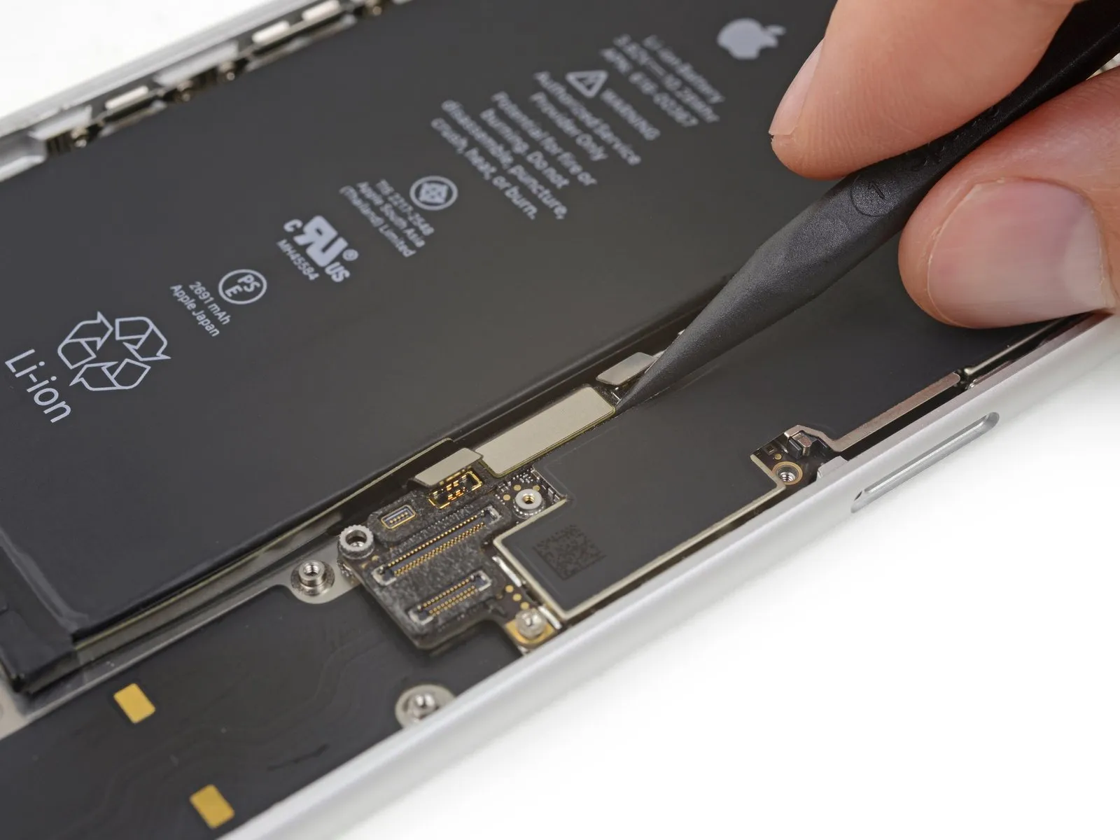
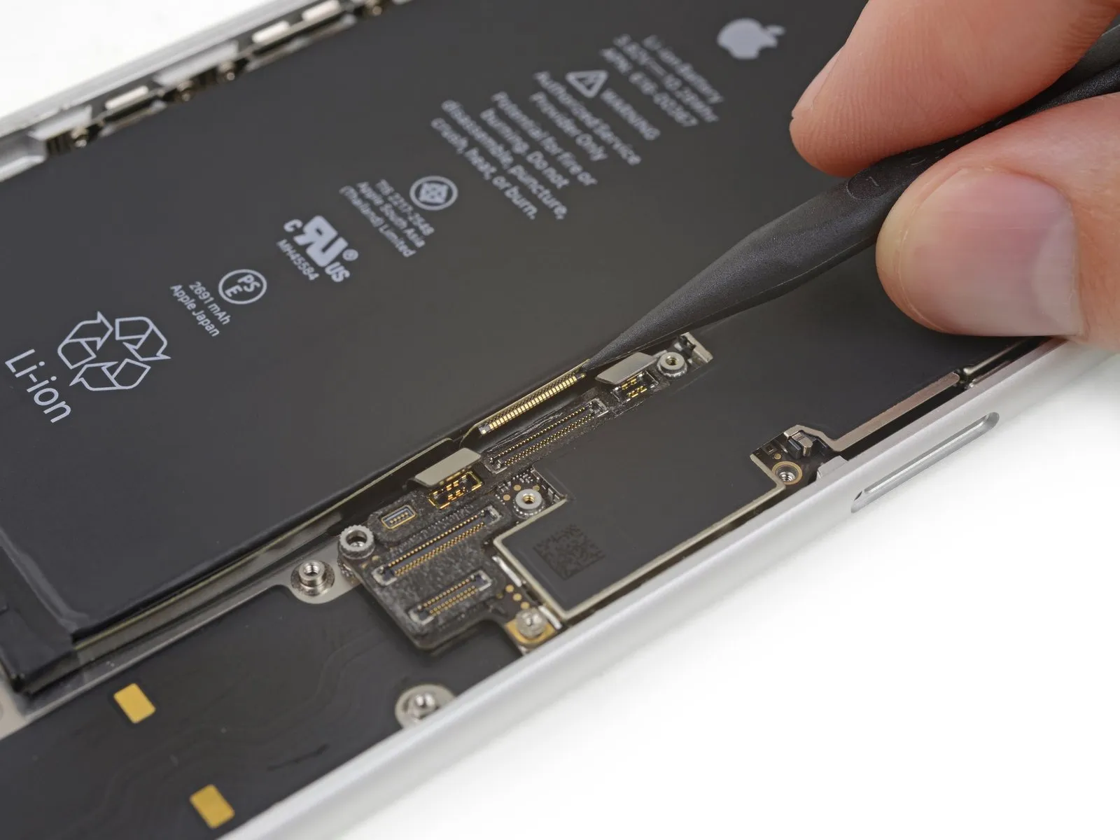
Employ the tip of a spudgerto carefully lift and release the flex cable connecting the Lightning connector assembly to the logic board.
Step 63
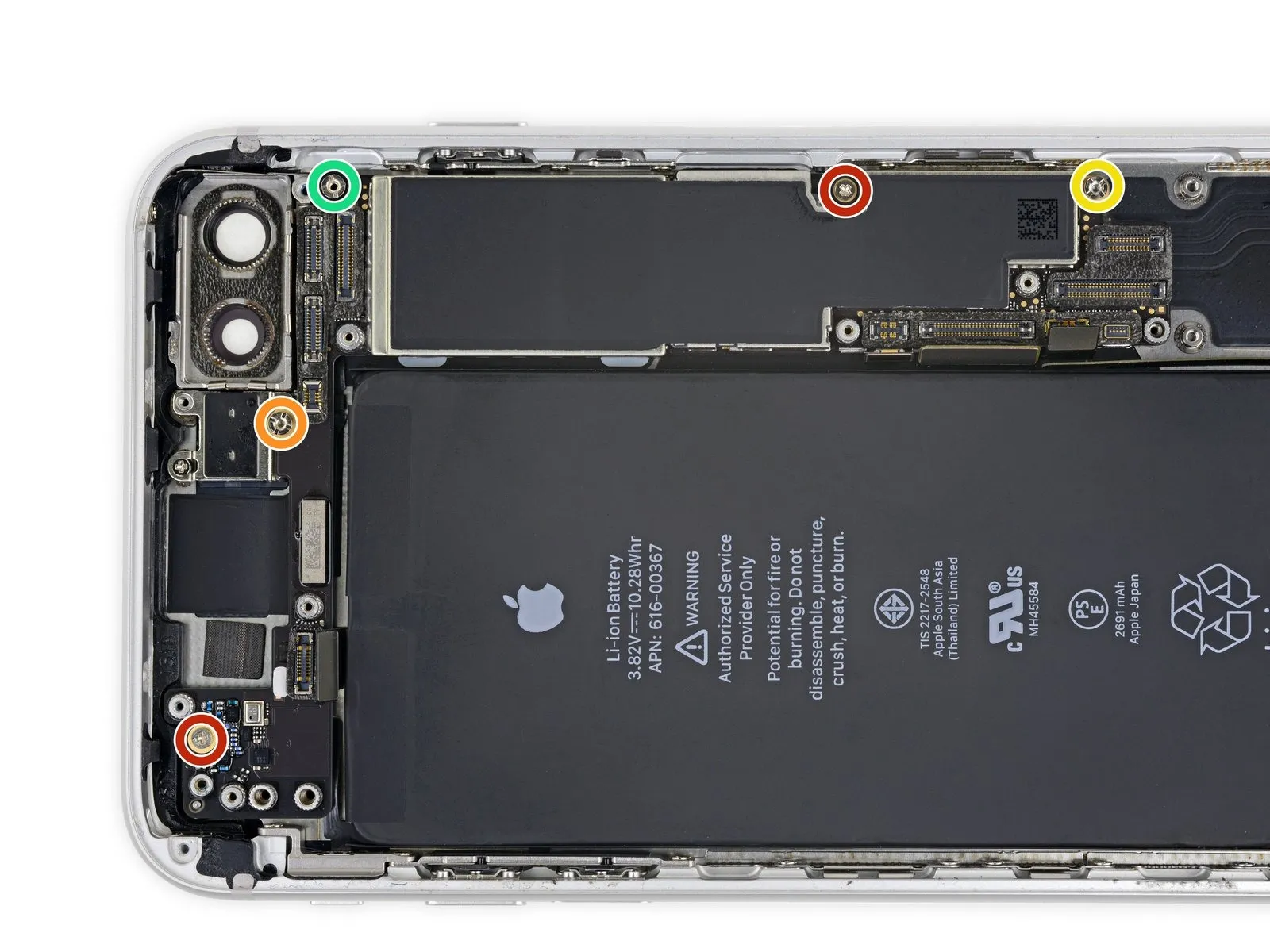
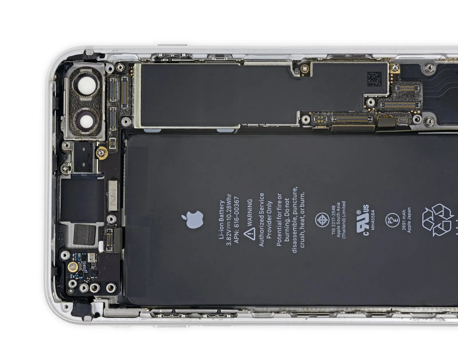
To detach the logic board, first, eliminate the five screws that hold it in place.
- Utilize two Phillips screws, each measuring 1.8 mm in length.
- A 2.3 mm standoff screw is also required for disassembly.
- Additionally, one standoff screw with a 2.4 mm dimension is needed.
- Furthermore, a 2.7 mm standoff screw must be removed.
- For optimal results when removing standoff screws, employ a specialized tool, specifically an IF145-343 along with a driver handle.
- If the recommended tool is unavailable, a small flathead screwdriver can be substituted; however, exercise heightened care to prevent slippage and potential harm to nearby components.
Step 64
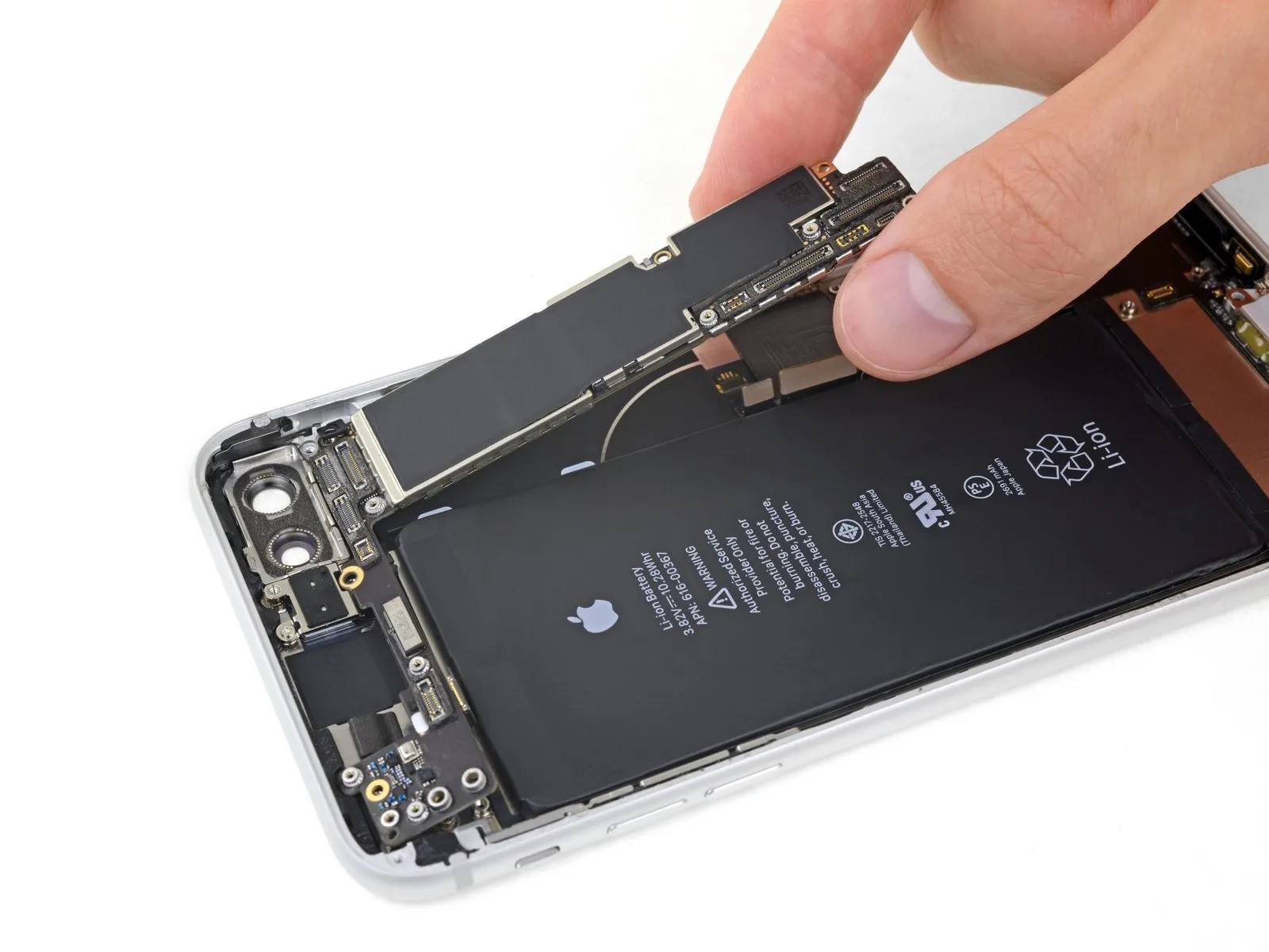
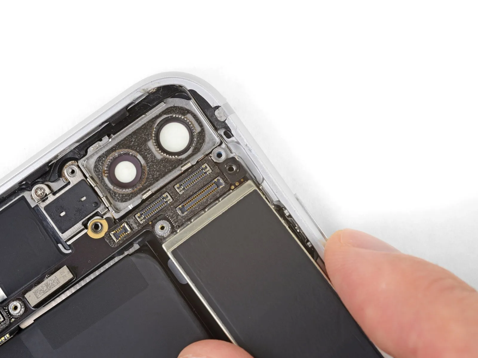
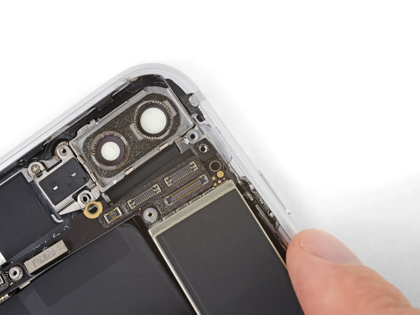
To detach the logic board, gently raise it from the lower borders and move it downwards within the iPhone's chassis.
Exercise caution to prevent the logic board from catching on any connecting wires.
When putting the device back together, observe the placement of the black grounding clip situated on the upper right side of the logic board, close to the rear-facing cameras; the logic board must be positioned beneath this clip.
Step 65
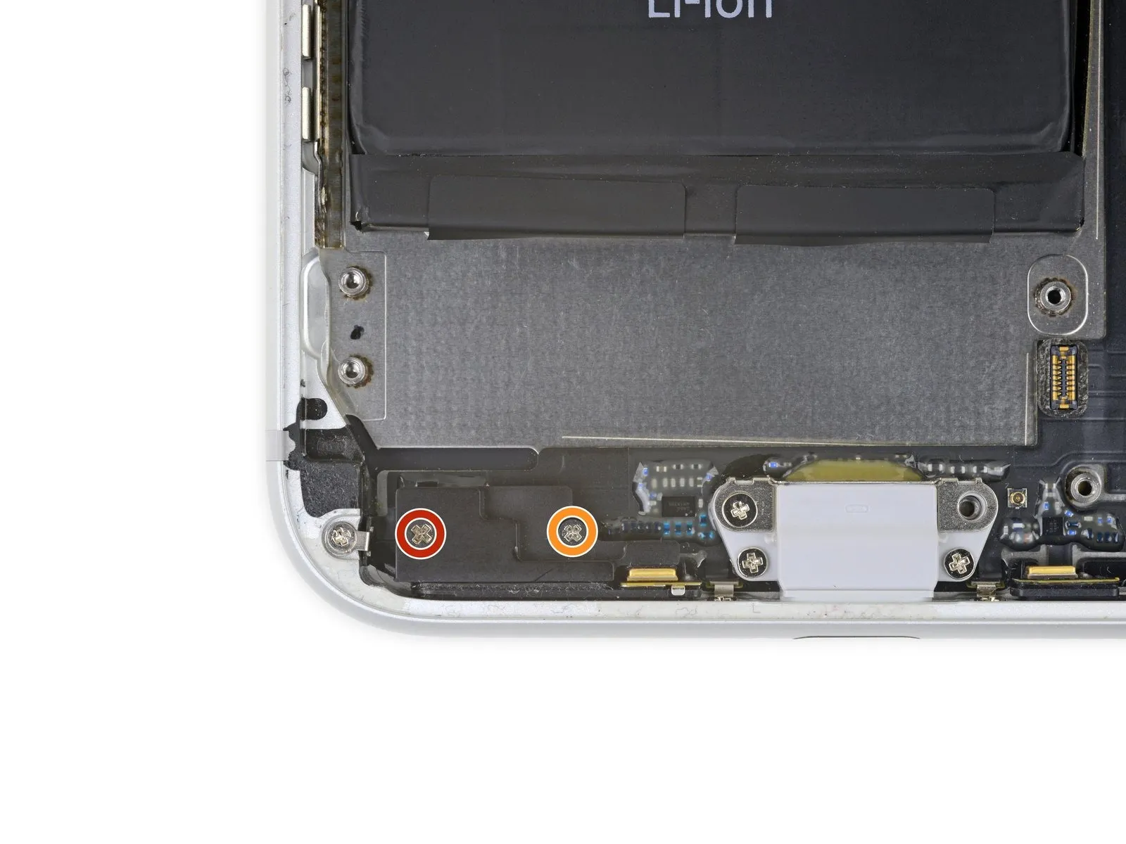
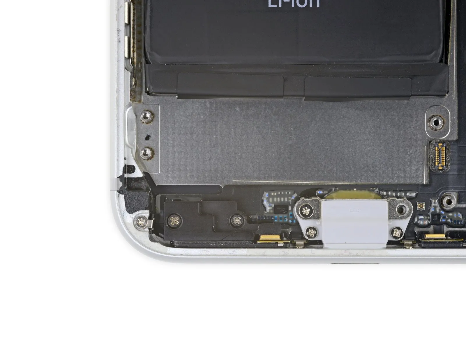
- Detachthe pair ofPhillips head fastenersthat hold the barometric vent in place, located at the lower-left edge of the iPhone:
A single 3.2-millimeter screw
along with a single 1.8-millimeter screw
Step 66
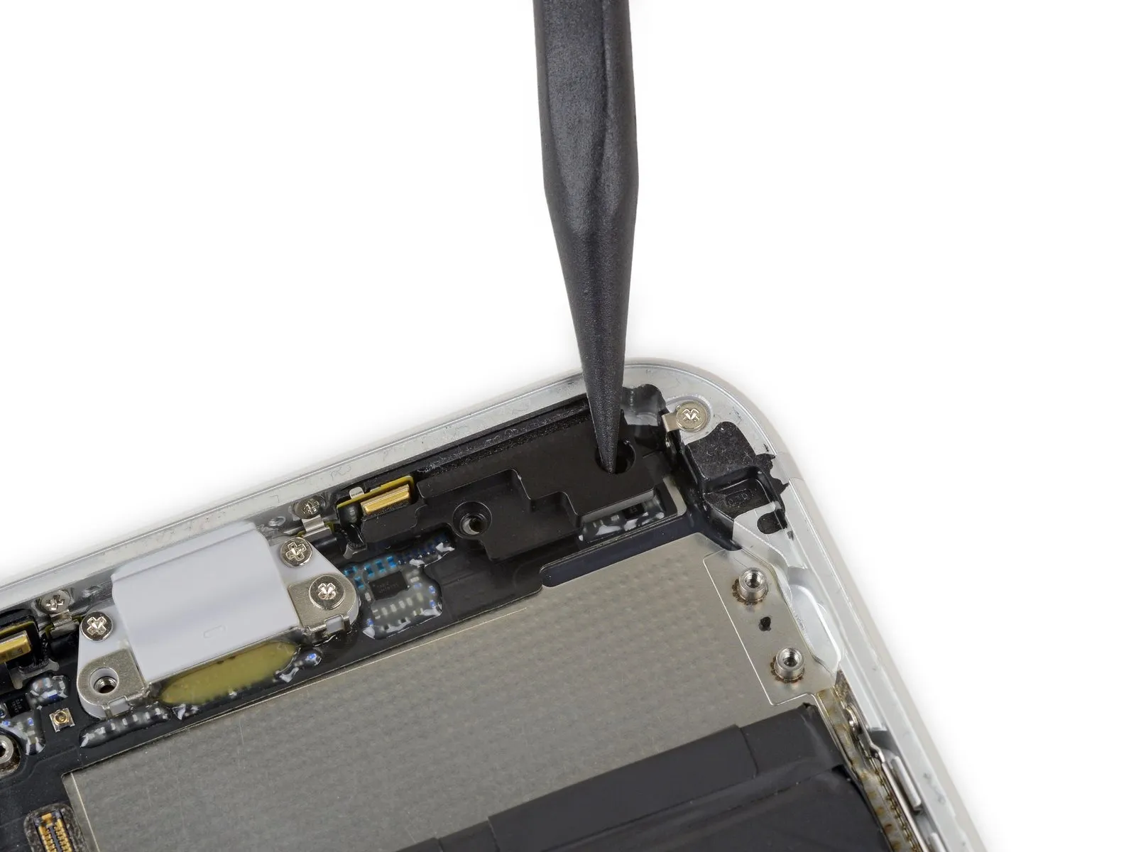
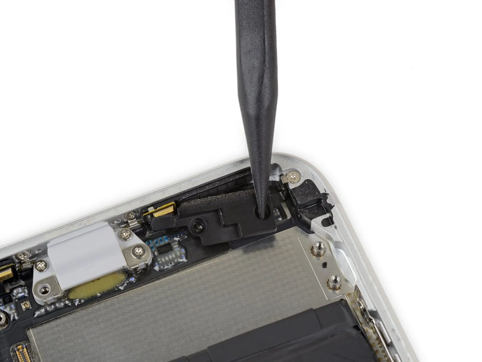
To release the barometric vent's adhesive bond to the iPhone's lower edge, carefully depress the vent inward, towards the battery compartment.
Step 67
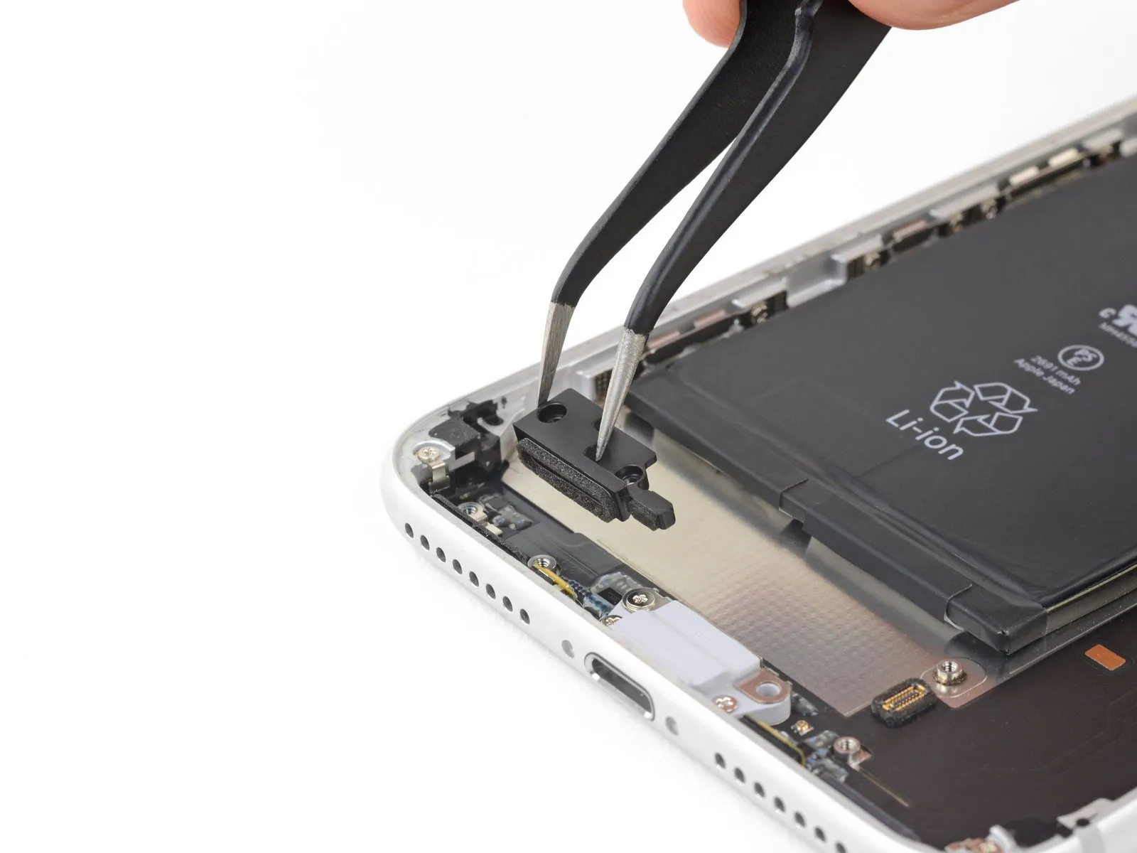
Detach the vent assembly.
Step 68
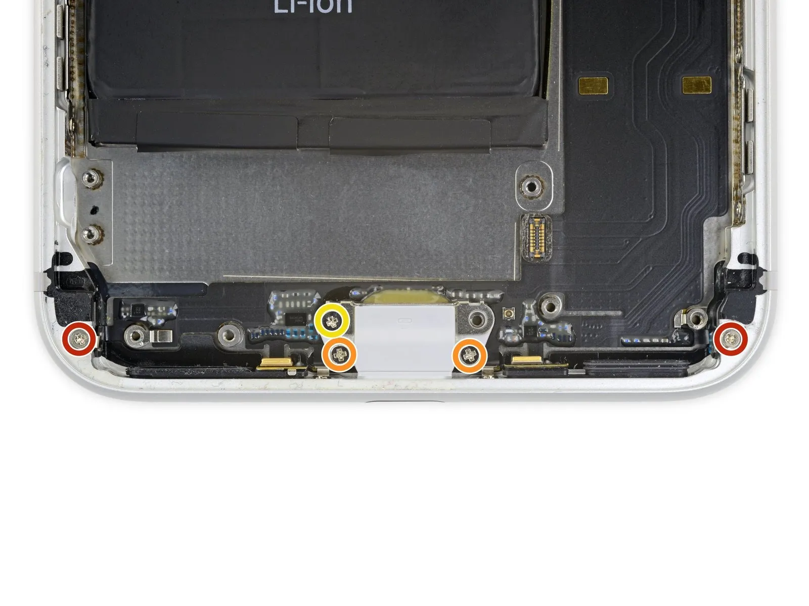
- Detachthe total of fivePhillips head fastenersthat hold the Lightning connector assembly in place on the back cover:
Utilize two screws measuring 1.2 millimeters in length
along with two screws measuring 2.4 millimeters in length
and a single screw measuring 2.5 millimeters in length
Step 69
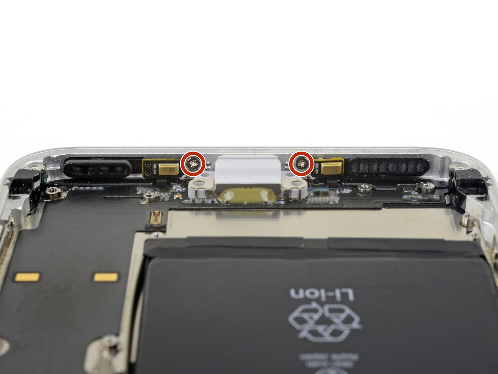
To detach the Lightning port from the iPhone's lower edge, first eliminate the pair of1.3 mm Phillips screwsthat are holding it in place.
Step 70
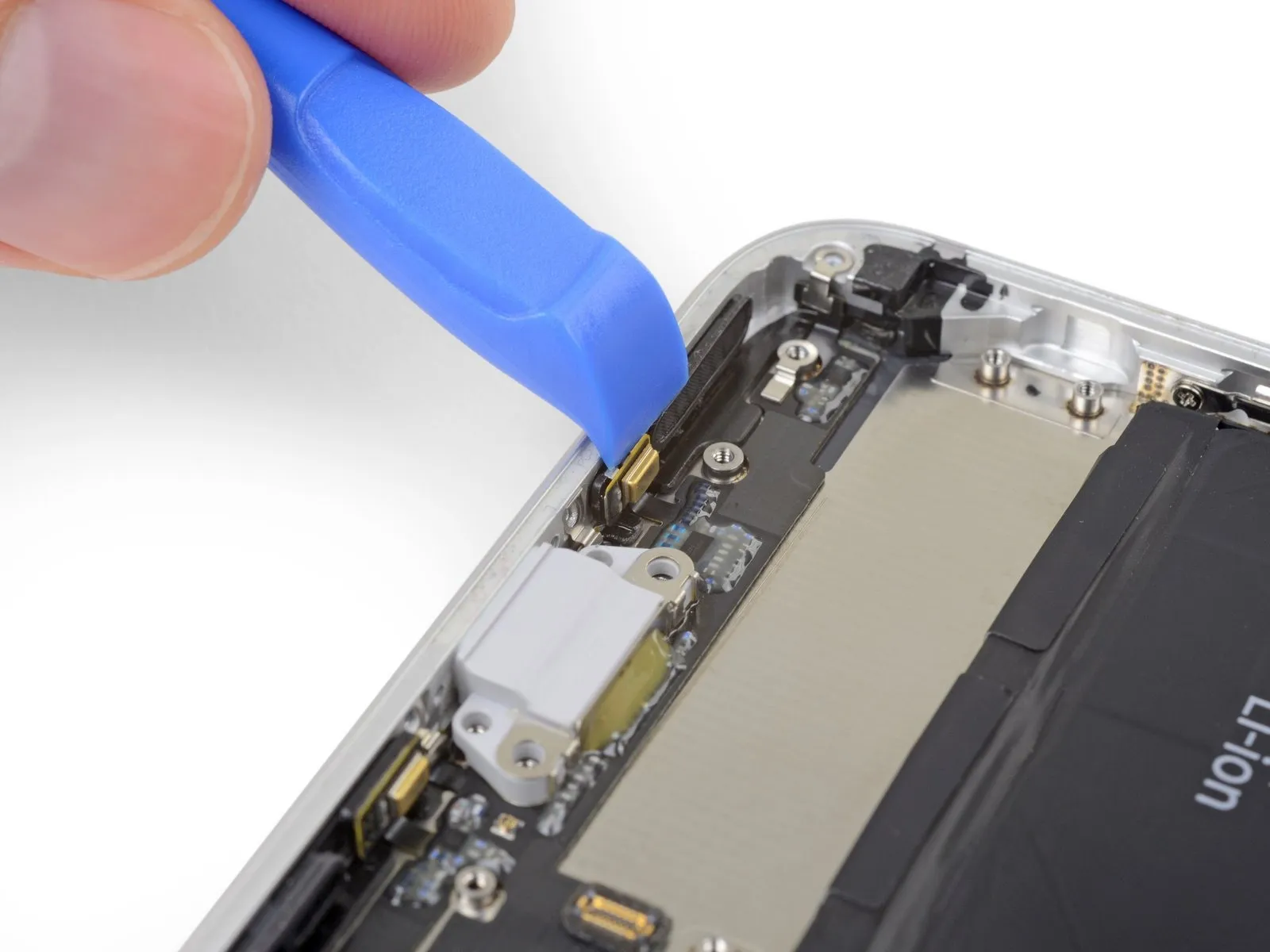
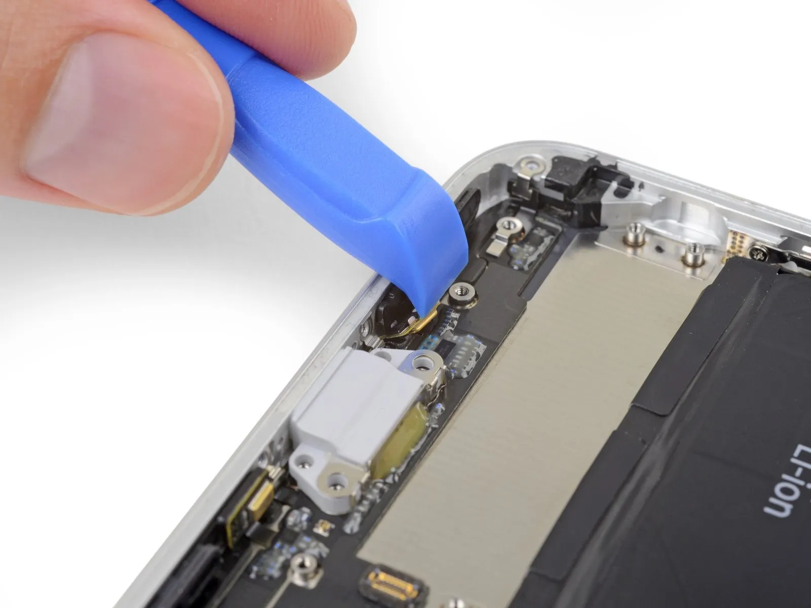
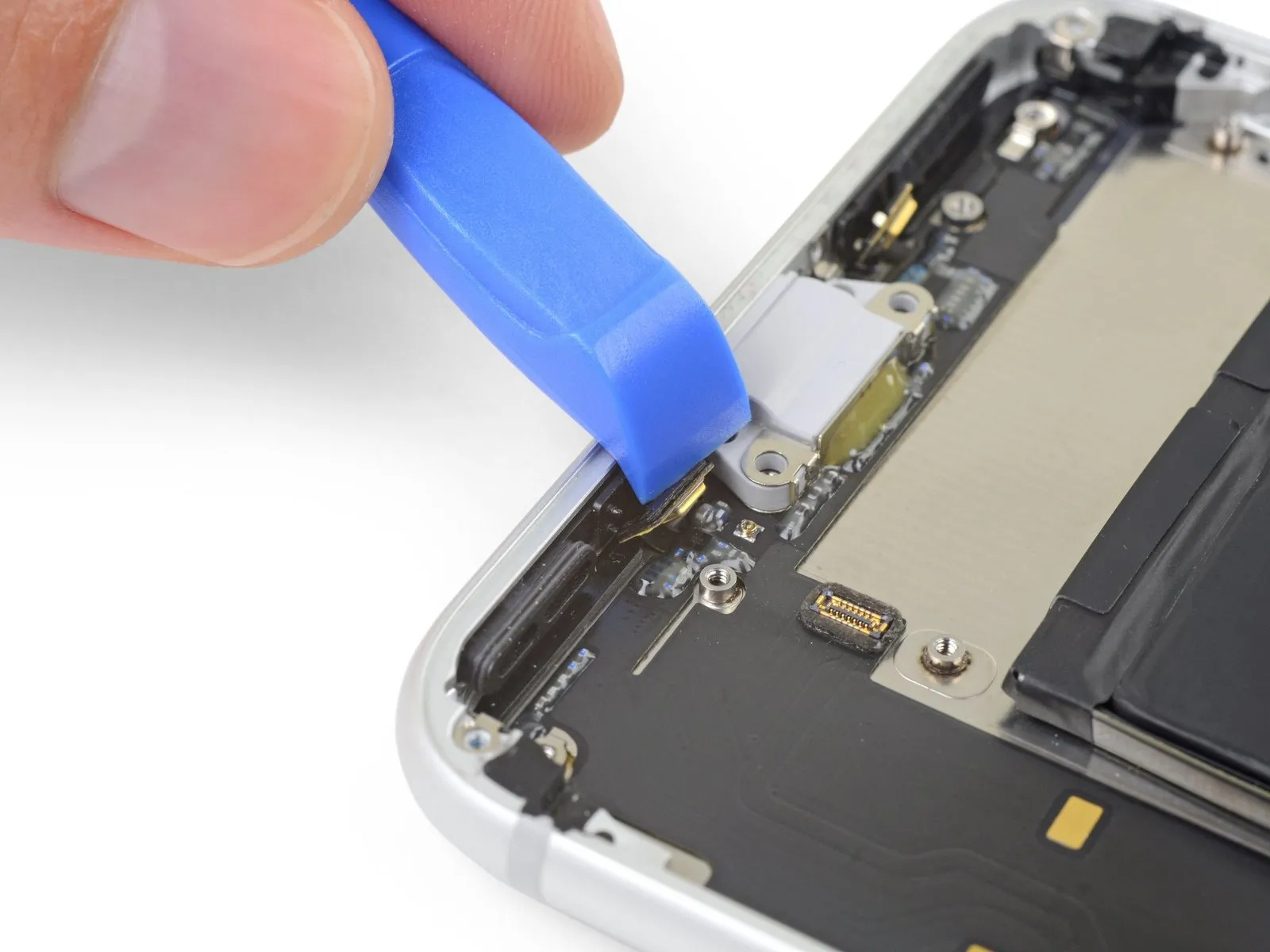
- Employ the pointed end of an iFixit Opening Tool to carefully disengage the two microphones from the adhesive that holds them in place along the iPhone's bottom edge.
- Refrain from attempting a full removal of the microphones; the objective is solely to loosen the adhesive bond, as illustrated.
Step 71
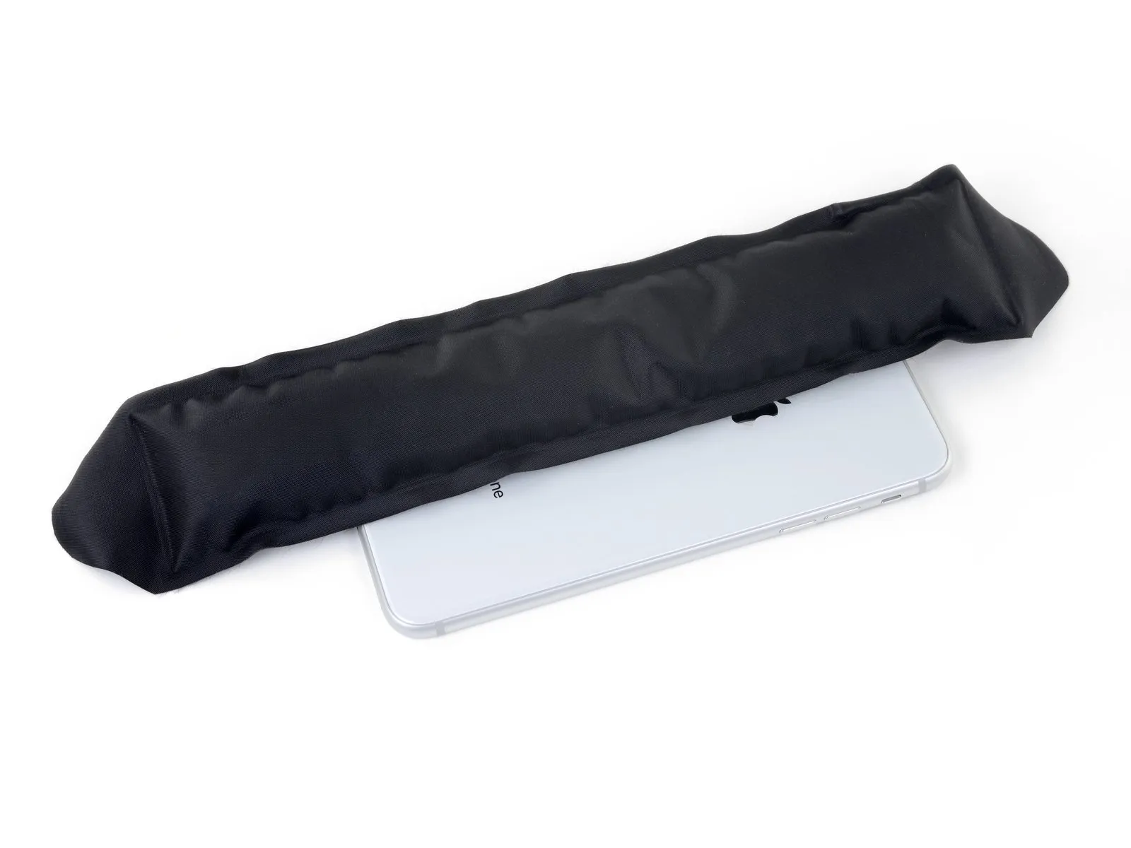
Utilize a device like an iOpener, or alternatively, a hair dryer, to apply heat to the rear enclosure's surface, specifically in the area behind the Lightning connector flex cable; this process will reduce the adhesive's firmness, thereby simplifying the separation of the flex cable.
Step 72
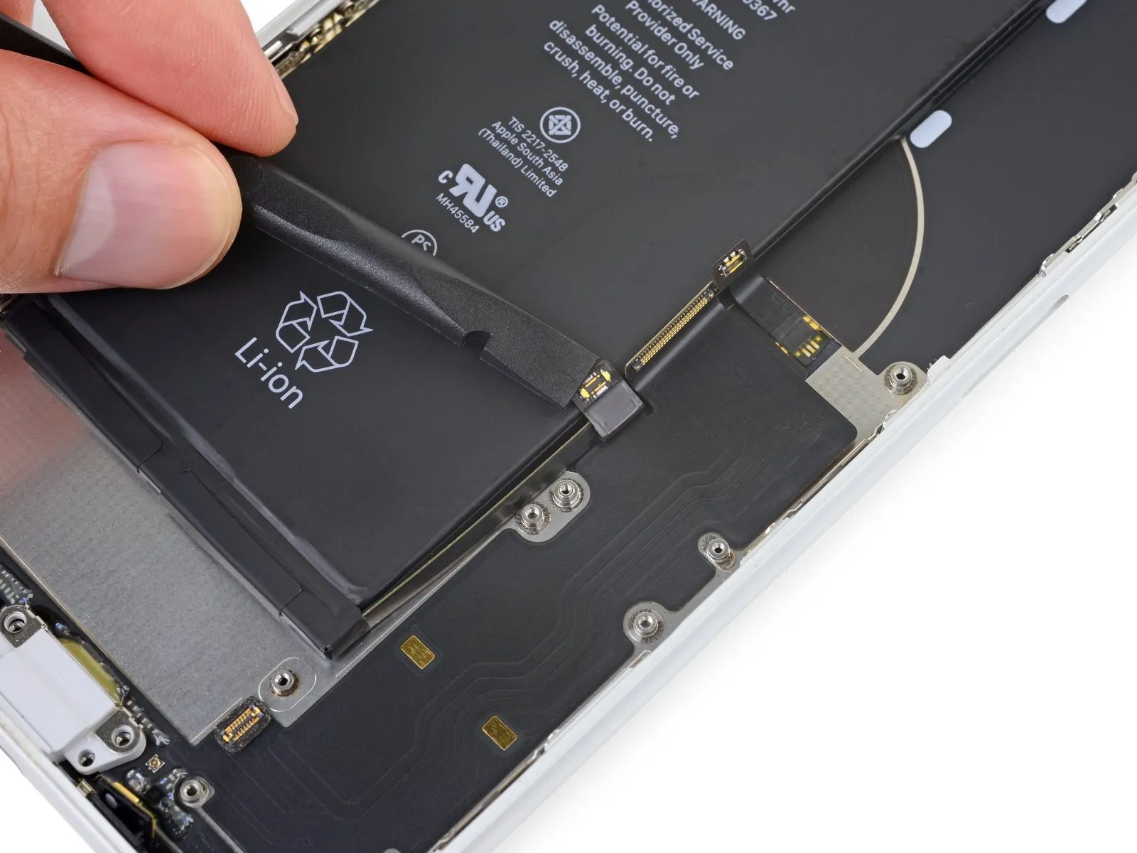
- Employing the planar surface of a spudger, carefully maneuver the battery flex cable connector back from the upper section of the Lightning connector assembly.
- Throughout the subsequent procedures, exercise caution to prevent unintended harm to the battery flex cable while disengaging the Lightning connector assembly.
Step 73
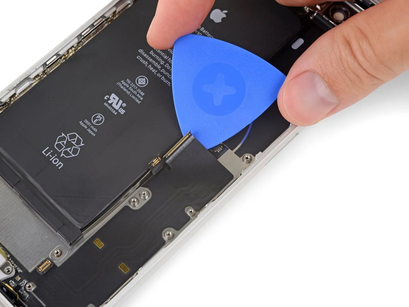
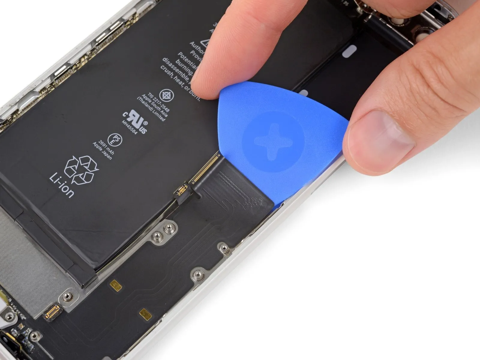
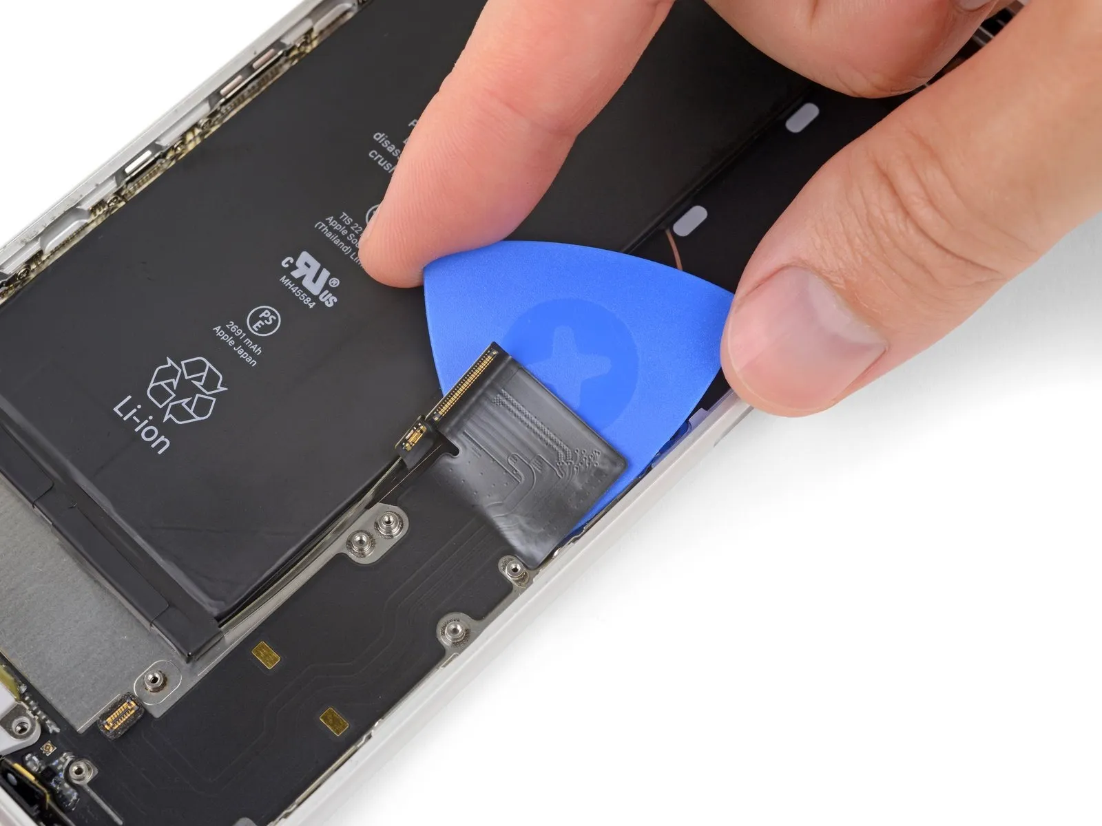
- Employ a specialized opening pick or a slender prying tool to create a gap beneath the upper section of theLightning connector assembly flex cable.
- Carefully move the pick towards the exterior of the iPhone, distancing it from the battery.
- A segment of the wireless charging coil is positioned directly below this section of theLightning connector flex cable. Excessive force during separation could potentially harm the coil.
- Should separation prove difficult, repeatedly apply heat to the area behind theLightning connector assembly flex cable utilizing a hair dryer or iOpener, to facilitate easier detachment.
Step 74
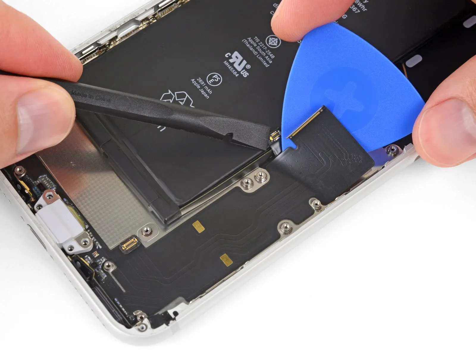
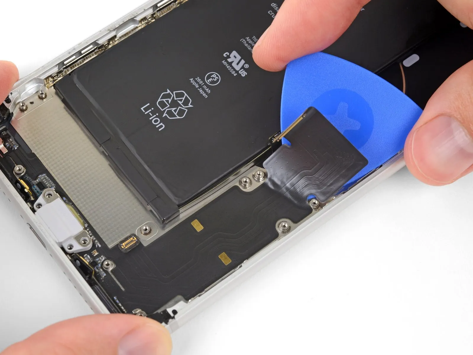
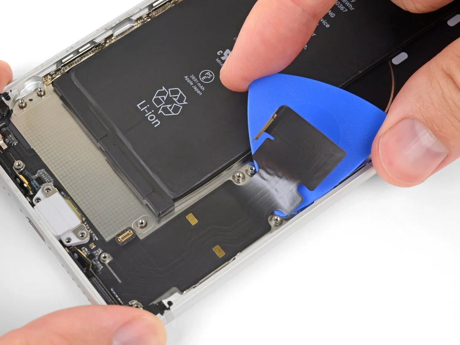
- Proceed with detaching the upper assembly of theLightning connector flex cable, exercising caution to prevent harm to surrounding parts.
- Maintain the battery connector in a carefully folded position to avoid potential damage.
- Exercise extreme care to prevent any harm to the battery; a compromised battery may release hazardous substances and/or ignite.
Step 75
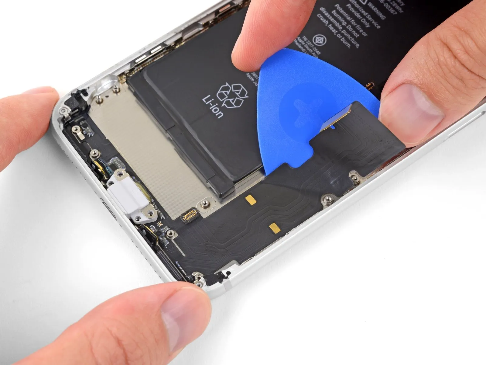
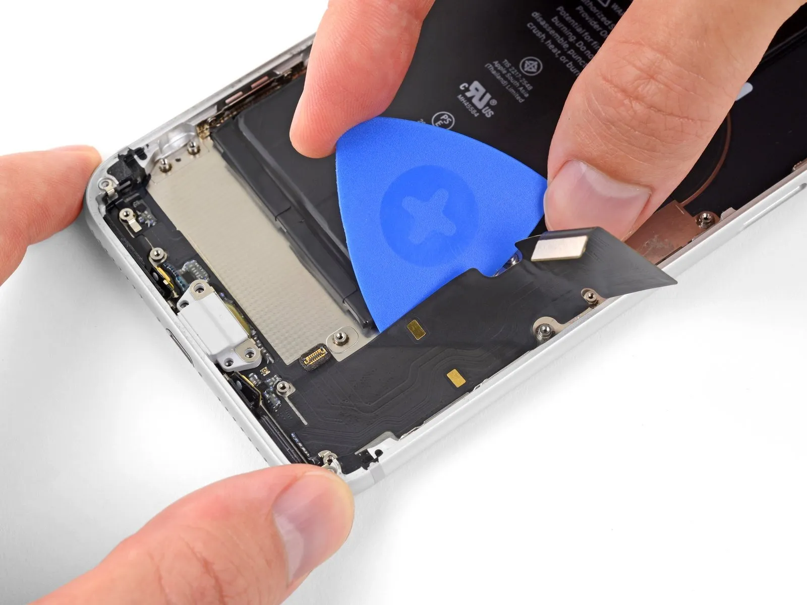
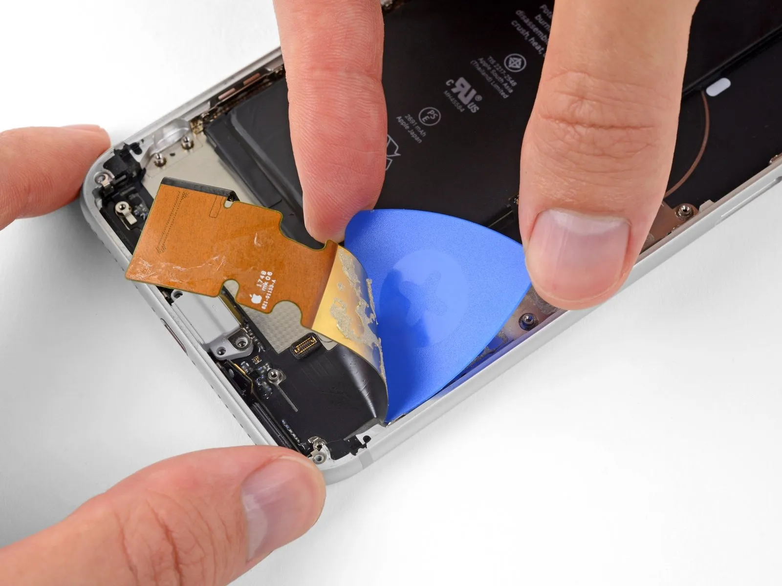
Proceed with detaching theflexible cable connected to the Lightning connector assemblyuntil the lower boundary of the battery is reached.
Step 76
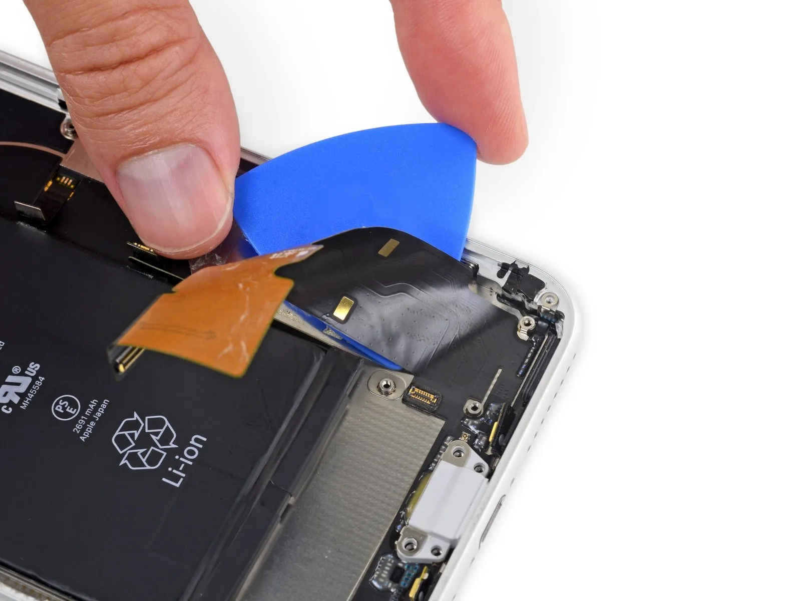
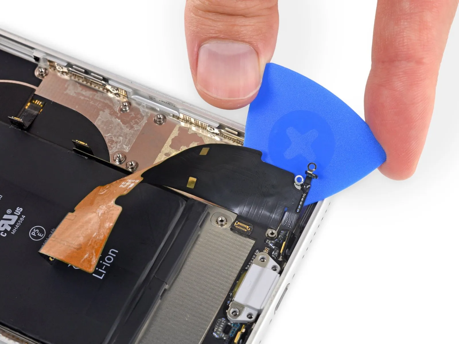
Using a specialized tool, gently insert it into the gap between the battery and the iPhone's outer casing, progressing from one corner to the opposite to release the adhesive bond.flex cable securing it to the device's frame.
Step 77
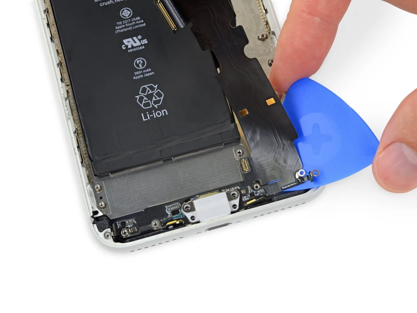
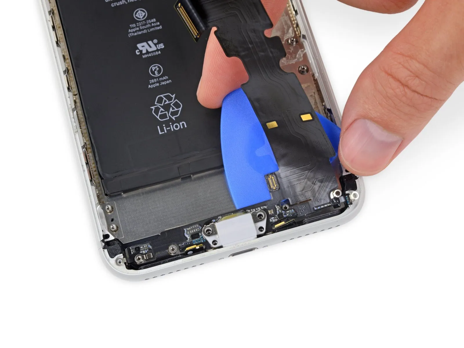
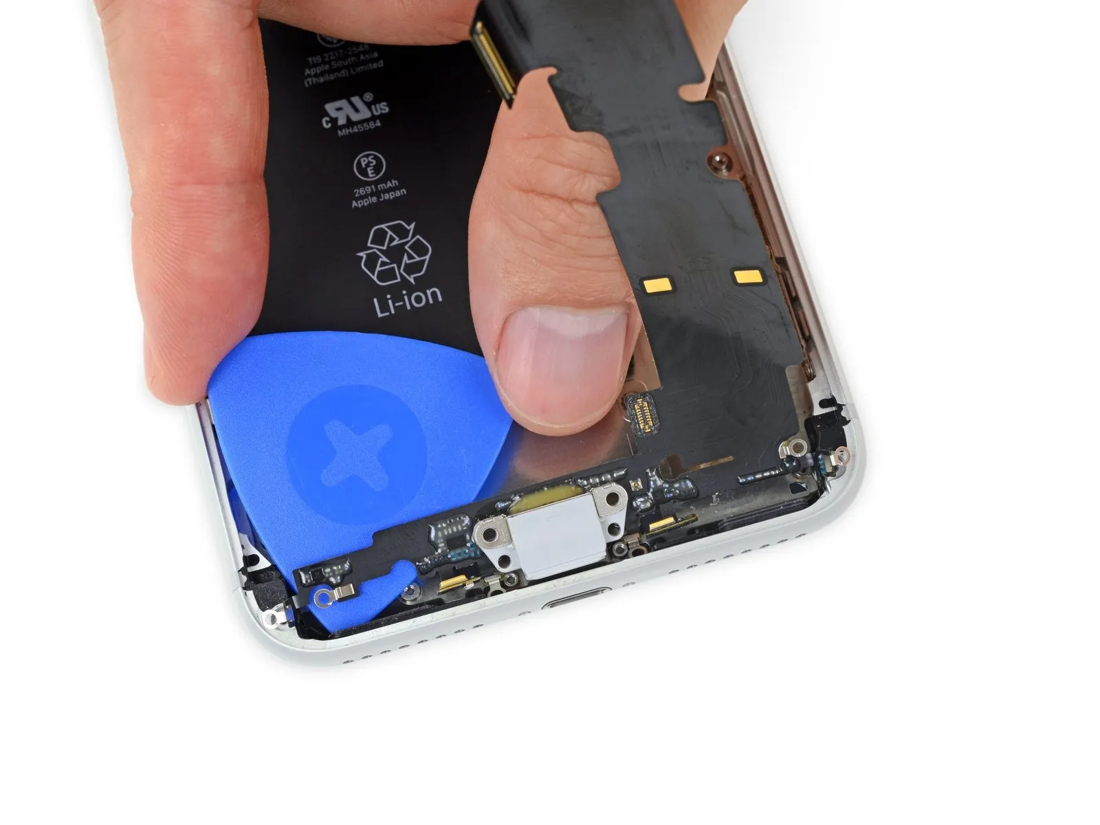
Step 78
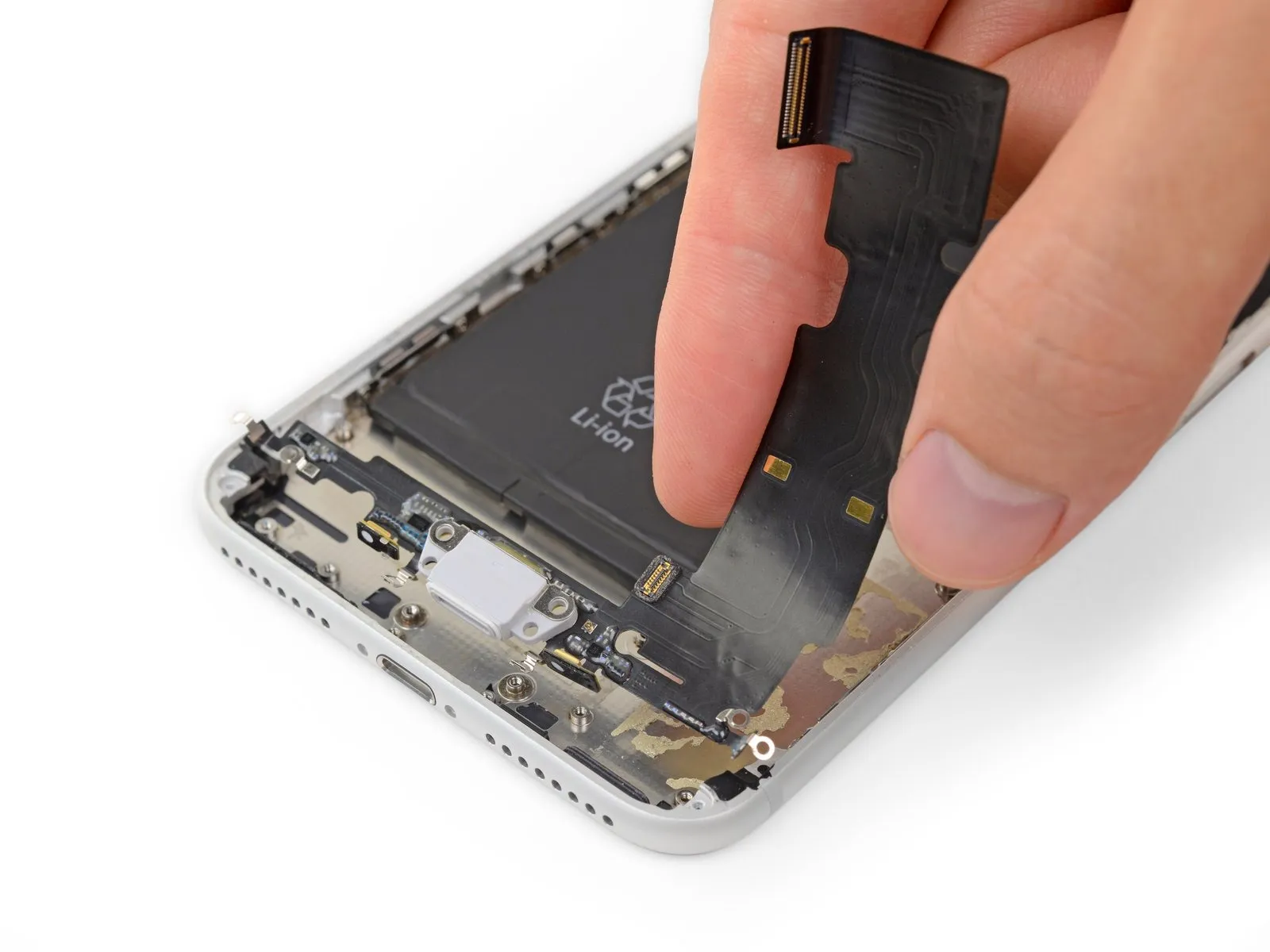
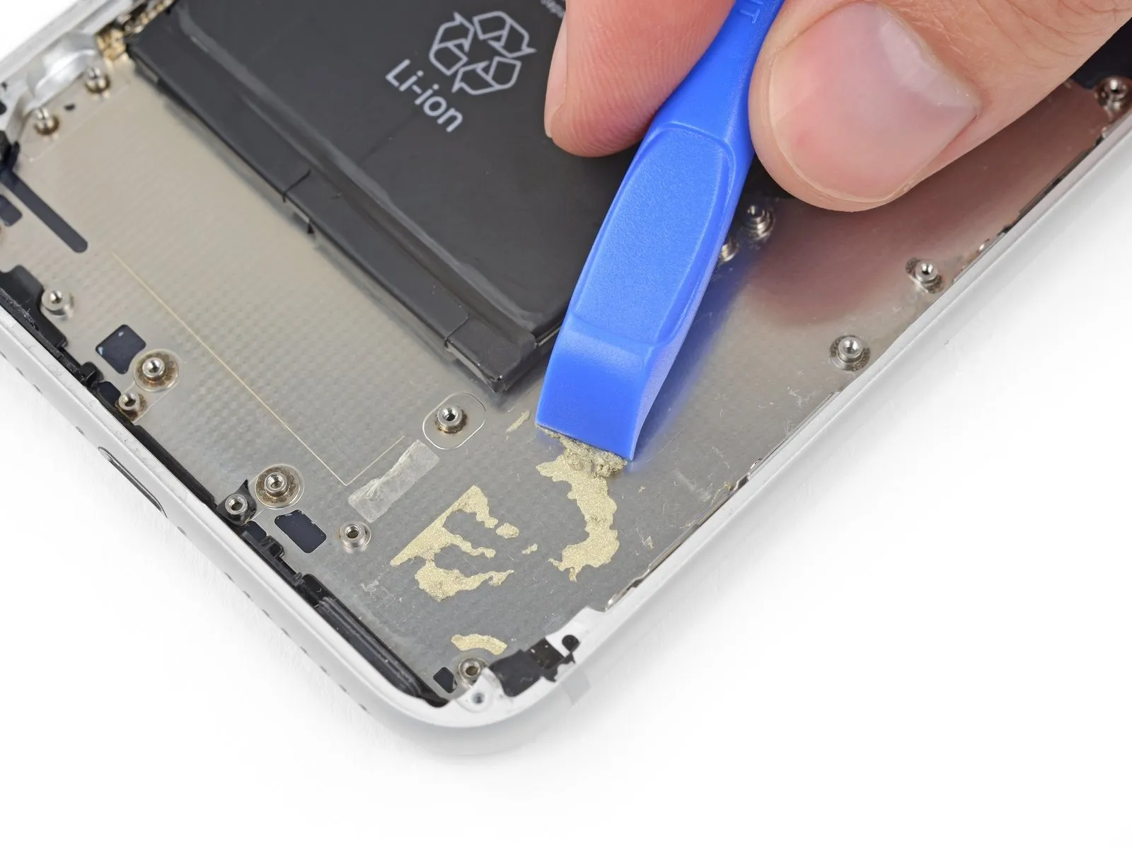
- Detach the Lightning connector assembly.
- Prior to either installing or substituting the Lightning connector assembly:
- Employ a non-metallic instrument to eliminate any traces of adhesive left on the rear case.
- Completely eliminate any lingering residue from the surface utilizing isopropyl alcohol (a concentration of less than or equal to 90%, or higher) and a cloth that produces no fibers. Apply the cleaning motion in a single direction, avoiding a reciprocating pattern.
Step 79
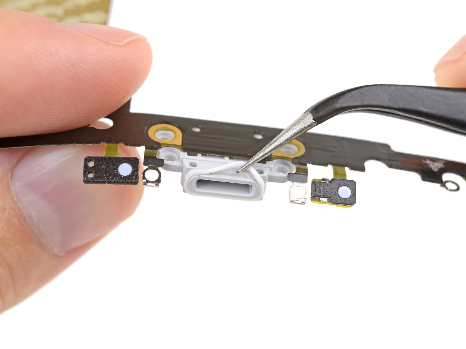
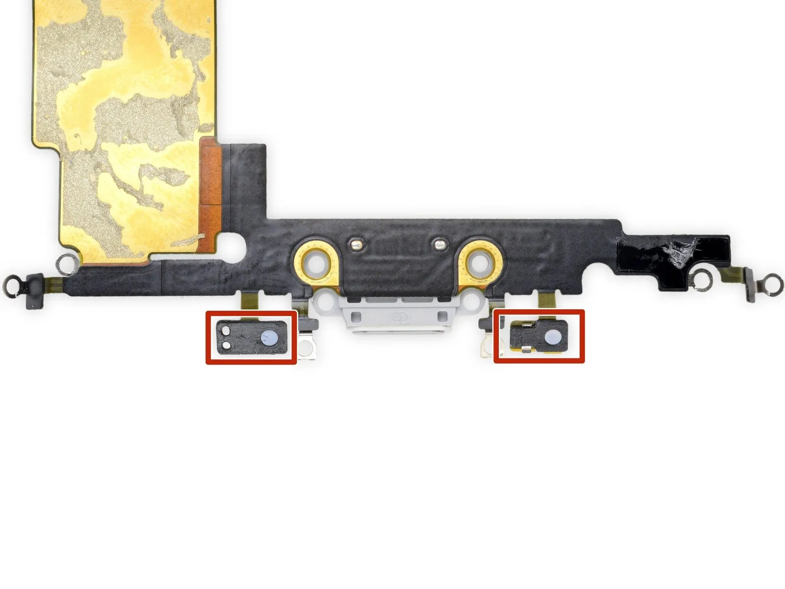
To safeguard your iPhone against liquid and dust, a rubber gasket is situated at the base of the Lightning connector. When replacing the Lightning connector assembly, it might be necessary to delicately detach and relocate this gasket to the substitute part.
Each microphone is shielded by a tiny adhesive patch, which also prevents liquid and dust from entering your iPhone. To achieve optimal performance, it is recommended to substitute both of these adhesive patches prior to installing the Lightning connector assembly.
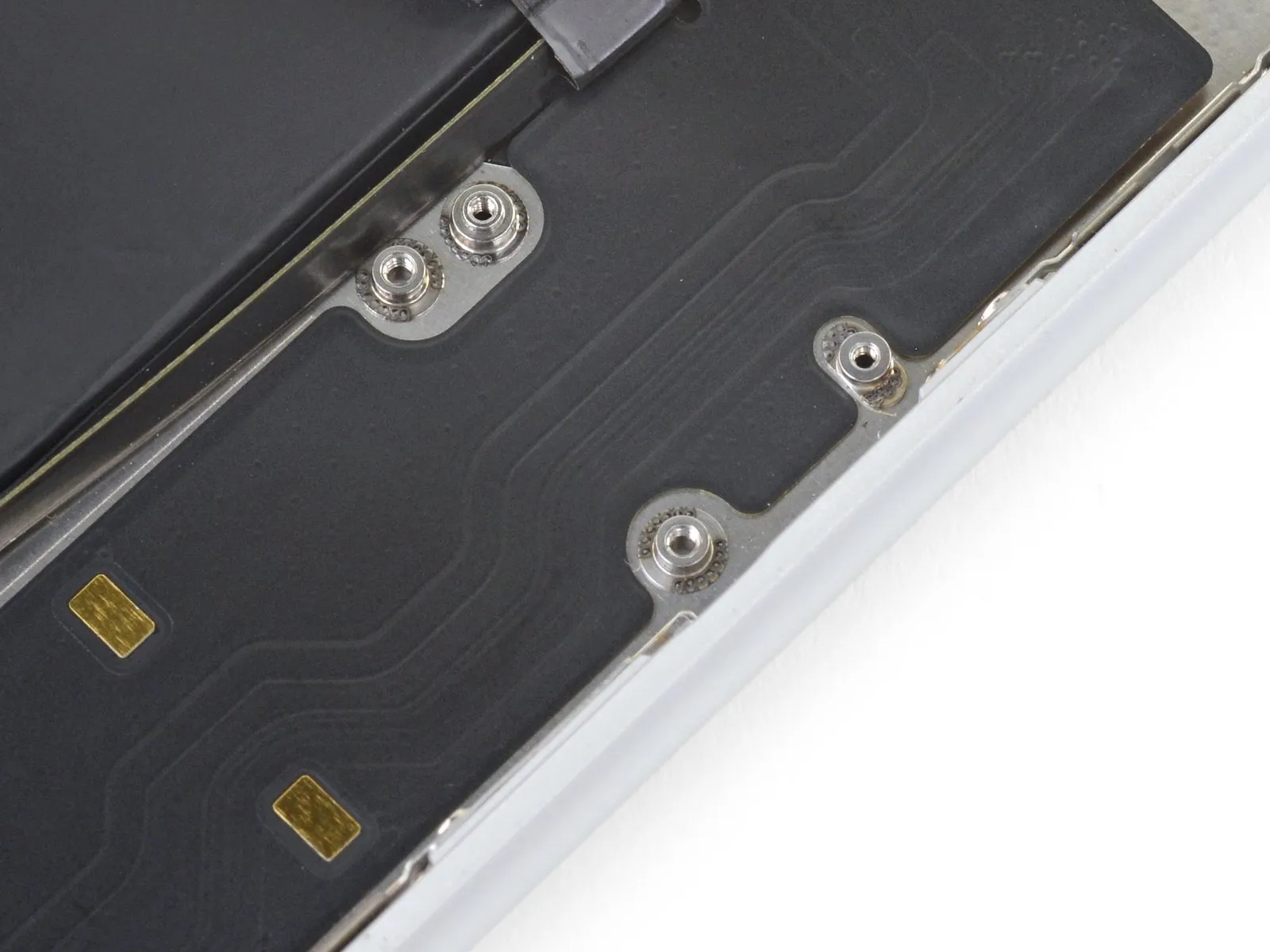
Significant Note:Ensure the new Lightning connector assembly is accurately aligned during the installation process, with the cable’s openings precisely positioned over the four screw bosses located on the rear case. Failure to do so will result in a flex cable misalignment, hindering its reconnection to the socket on the logic board.