iPhone 7 Plus Rear Camera Lens Glass Replacement
This document details the procedure for substituting the camera lens component on the iPhone 7 Plus.iPhone 7 Plus.
Step 1 | Pentalobe Screws
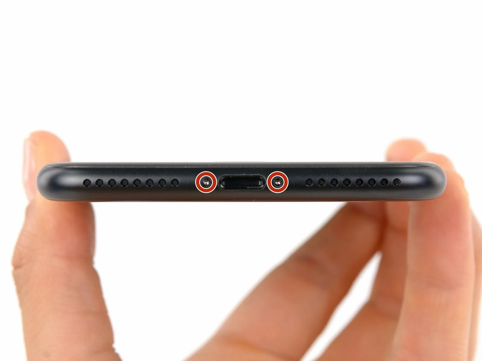
- As a crucial safety precaution prior to commencing the repair, ensure your iPhone's battery level drops below 25%; a fully charged lithium-ion battery presents a fire hazard and potential explosion risk if it sustains accidental physical damage.
- To ensure safety and prevent short circuits, completely de-energize the iPhone by turning it off before starting the disassembly process.
- Utilizing a P2 screw bit, or a similar tool, carefully unscrew and remove the pair of 3.4 mm pentalobe screws located along the iPhone's lower edge.
- Separating the iPhone's display assembly will inevitably damage the integrated waterproof seals.To maintain the iPhone's water resistance, prepare replacement seals beforehand; alternatively, exercise extreme caution to prevent liquid ingress if you intend to reassemble the device without new seals.
Step 2 | Opening Procedure

- Applying warmth to the iPhone's bottom perimeter assists in loosening the adhesive that holds the display in place, which simplifies the opening process.
- Employing a hairdryer or utilizing an iOpener, direct heat to the lower edge of the iPhone for approximately one minute to reduce the adhesive's tackiness.
Step 3


- Secure a suction cup to the bottom portion of the front panel, positioning it directly over the home button's location.
- Ensure the suction cup's surface area remains clear of the home button to guarantee a complete bond between the cup and the front glass.
- For displays exhibiting severe cracking, applying a sheet of transparent packing tape can improve suction cup adhesion; alternatively, utilize a robust adhesive tape in place of the suction cup. As a last resort, superglue can be employed to affix the suction cup to the fractured screen.
Step 4


- Apply steady, consistent upward force to the suction cup to generate a small separation between the front panel assembly and the rear casing.
- Carefully slide the flat end of a spudger tool into the newly formed gap.
- The display is secured by a robust, waterproof adhesive; overcoming this initial seal requires considerable force. Should you encounter difficulty in creating this separation, gently move the screen in an upward and downward motion to reduce the adhesive's strength, allowing for spudger insertion.
- Maintain upward pressure on the suction cup and rotate the spudger to expand the space between the display and the rear case.
Step 5


- Begin by positioning the planar extremity of the specialized tool, a spudger, into the gap situated between the device's front panel and its rear enclosure, specifically at the lower-left corner.Advance the spudger along the left side of the iPhone, initiating at the bottom and progressing upward toward the volume adjustment buttons and the mute switch, to sever the adhesive bonds securing the display assembly.Avoid attempting to separate the display from the rear case at the upper edge, because it is secured by fragile plastic retaining clips that could fracture.The spudger is the tool being referenced.
- The lower left edge is the location being referenced.
- The adhesive is the material being separated.
Step 6


- Extract the spudger from the phone's left side, then position the flat tip into the lower-right corner.
- Advance the spudger along the right side of the device towards the upper corner, separating the adhesive securing the display assembly.
Step 7


- To detach the display assembly and gain access to the iPhone's internal components, utilize the suction cup and apply upward force.
- Exercise caution and limit the display's elevation to a maximum angle of10°because fragile, thin ribbon cables are situated along the device's right side, facilitating communication between the display and the main circuit board.
Step 8


- To detach the suction cup from the front panel, grasp and lift the small protrusion located on its surface.
Step 9


Step 10


- To release the retaining clips securing the display assembly, gently move it away from the phone's upper boundary.
- Initiate the opening process of the iPhone by pivoting the display upwards, beginning from the left-hand side, mimicking the action of opening a book's cover.
- Refrain from completely detaching the display at this stage, because multiple delicate ribbon cables remain connected to the iPhone's logic board.
Step 11 | Battery Disconnection
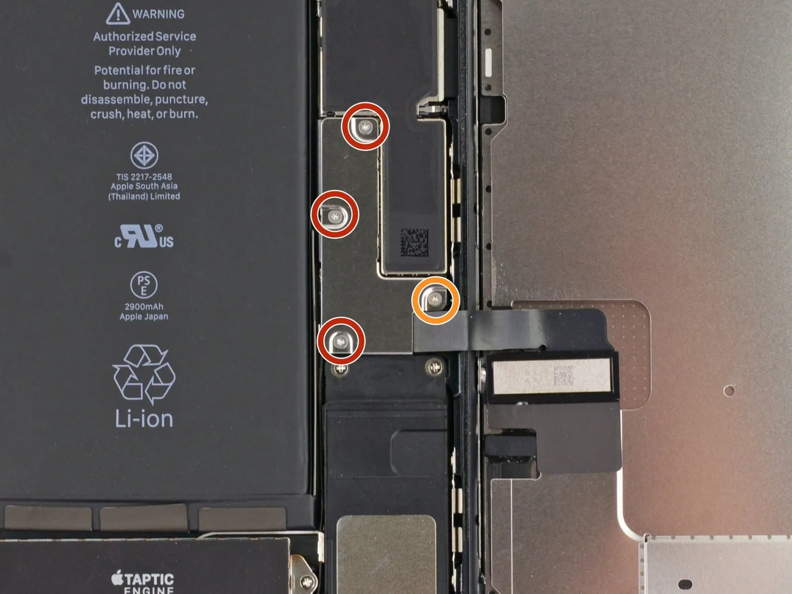
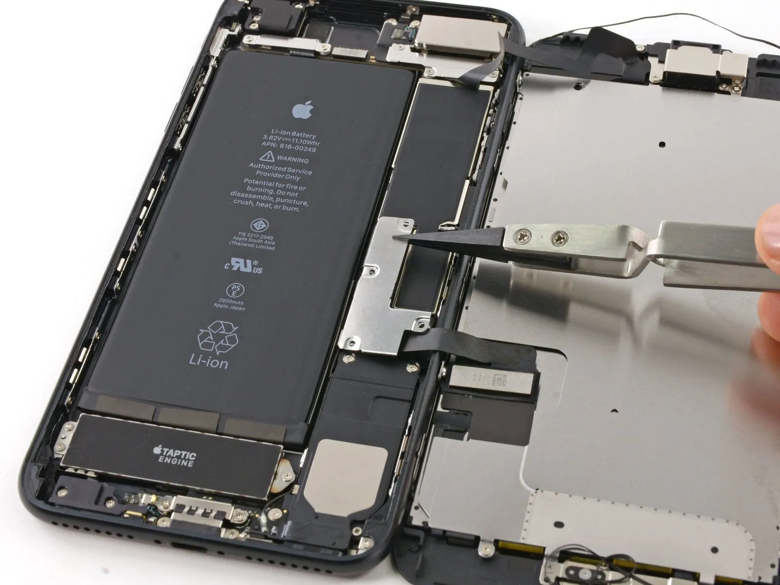
- To detach the lower display cable bracket from the logic board, carefully extract the four tri-point Y000 screws that hold it in place.
- Three 1.2 mm screws
- One 2.6 mm screw
Step 12

Step 13
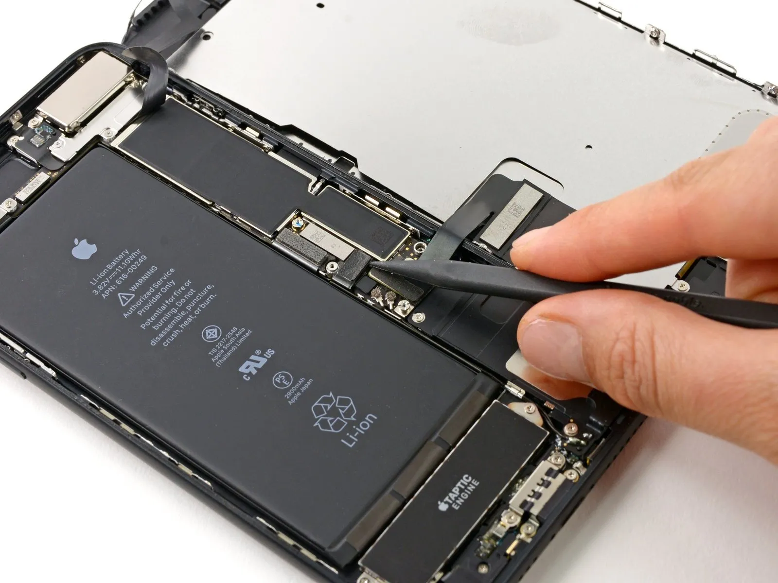


- Employ the tip of a spudgerto disengage the battery connector from its corresponding receptacle on the logic board.
- Gently elevate the connector cable a small amount to ensure it remains disconnected from the socket, thereby preventing any electrical current from reaching the device.
Step 14 | Display Assembly
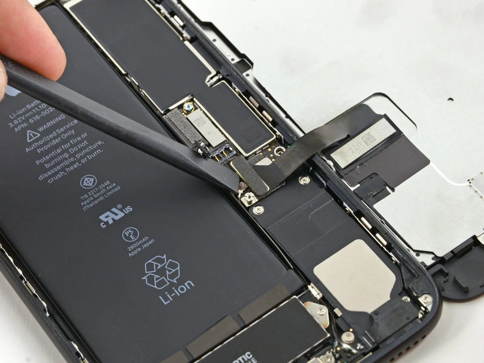


- Employ the planar edge of aspudgeror a fingernail to release the two lower display connectors; achieve this by applying upward pressure directly above them to separate them from their corresponding locations on the logic board.
- To secure the connectors during reassembly, apply downward force to one terminus until an audible click is heard, then repeat this process for the remaining terminus. Avoid applying pressure to the central portion of the connector; even minor misalignment can result in bending, which may lead to irreversible damage.
Step 15
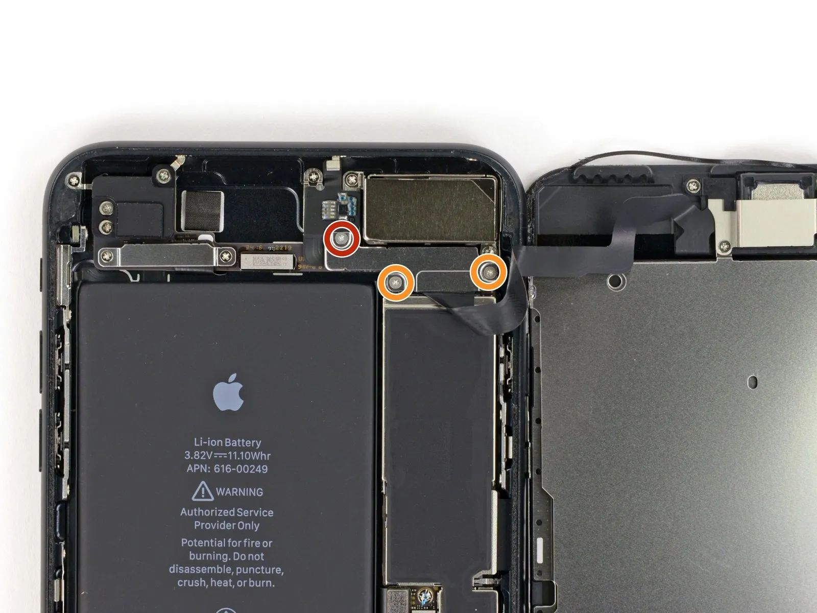


- To detach the bracket that covers the connector for the front panel sensor assembly, first extract the three screws with a tri-pointY000 driverThese screws, one measuring 1.3 mm and two measuring 1.0 mm, hold the bracket in place.
Following screw removal,carefully lift the bracket away from the device.
Ensure all screws are retained for reassembly.The bracket's removal allows access to the sensor assembly connector. - Proceed with caution to avoid damaging adjacent components.
Step 16
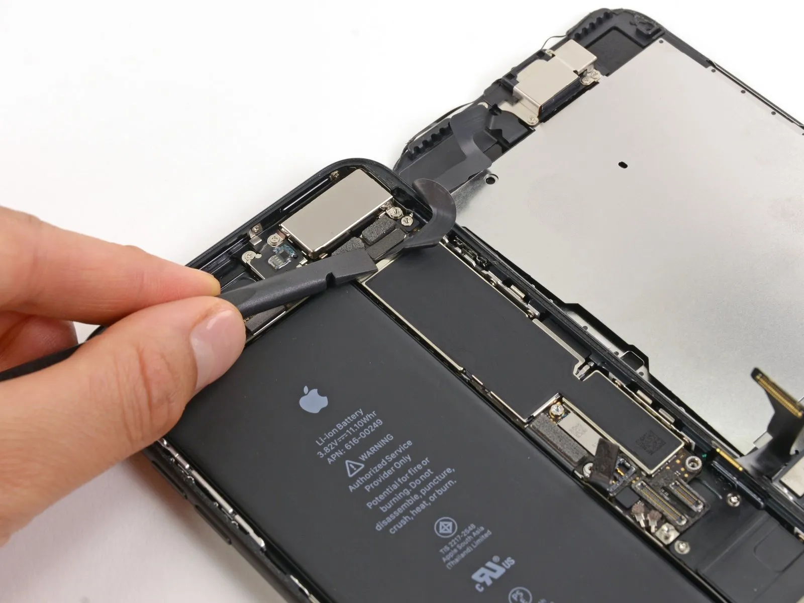

- To prevent damage, detach the connector linking the front panel sensor assembly to its socket on the main circuit board.
- To reduce the likelihood of deformation, ensure this press-fit connector is reattached incrementally, connecting one side at a time.
Step 17
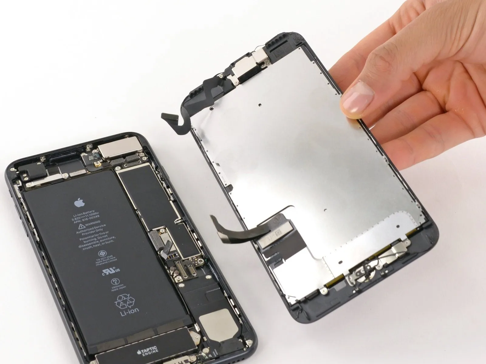
- Detach the display assembly from the device.
- If you intend to substitute the adhesive securing the display's perimeter during reassembly, halt the process at this stage.
Step 18 | Rear-Facing Cameras

- To detach the bracket that holds the rear camera in place, it is necessary to eliminate the two screws that fasten it.
The screws are secured with a Phillips head, measuring 1.6 mm in width.
Additionally, a standoff screw is present, with a diameter of 2.2 mm. - For optimal screw removal, a specialized standoff screwdriver or bit is recommended.
- If a standoff screwdriver is unavailable, a small flathead screwdriver can be employed as a substitute; however, exercise heightened care to prevent slippage and potential harm to nearby parts.
Step 19
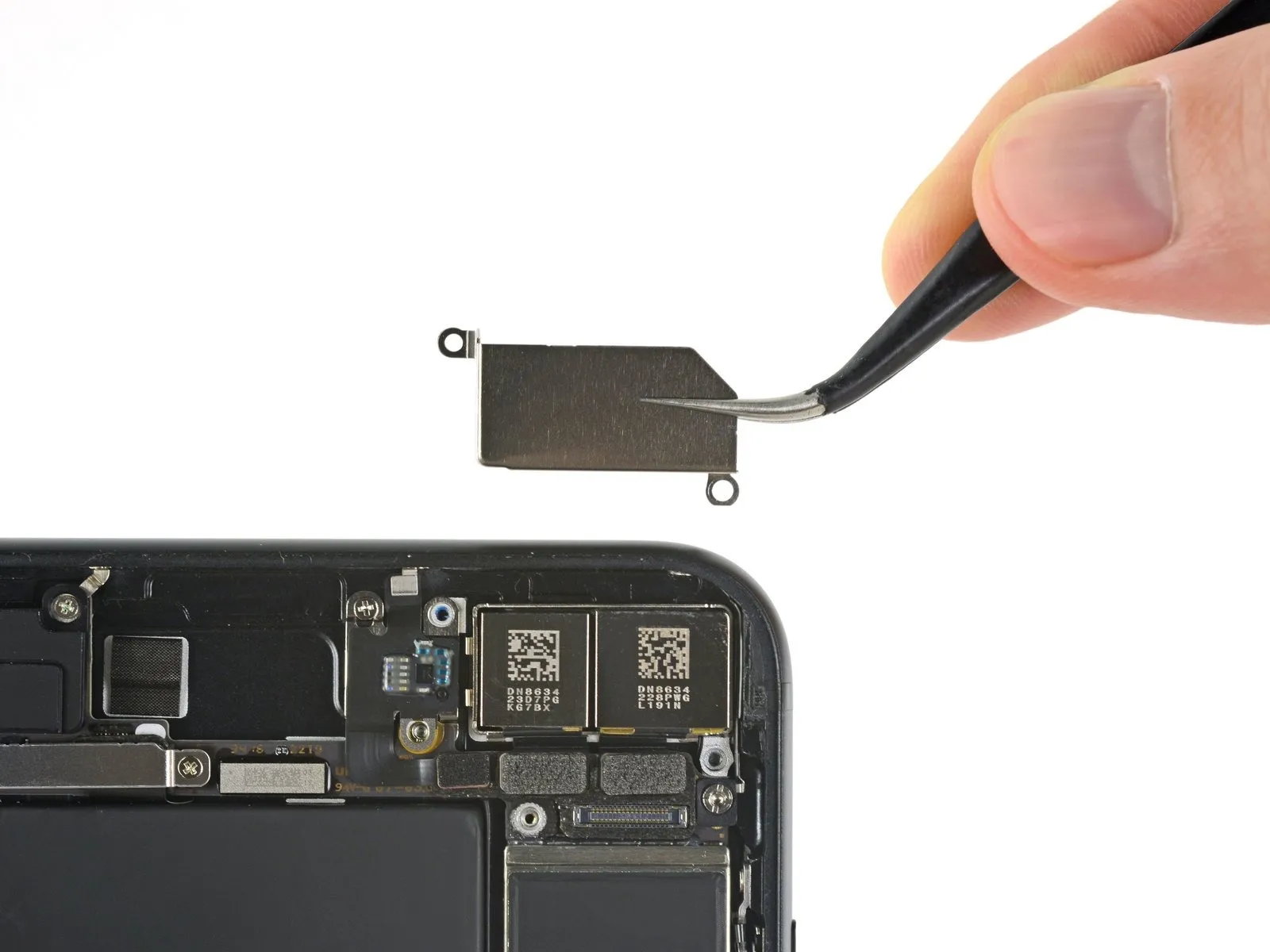
- Carefully detach the protective cover that shields the rear camera module.
Step 20
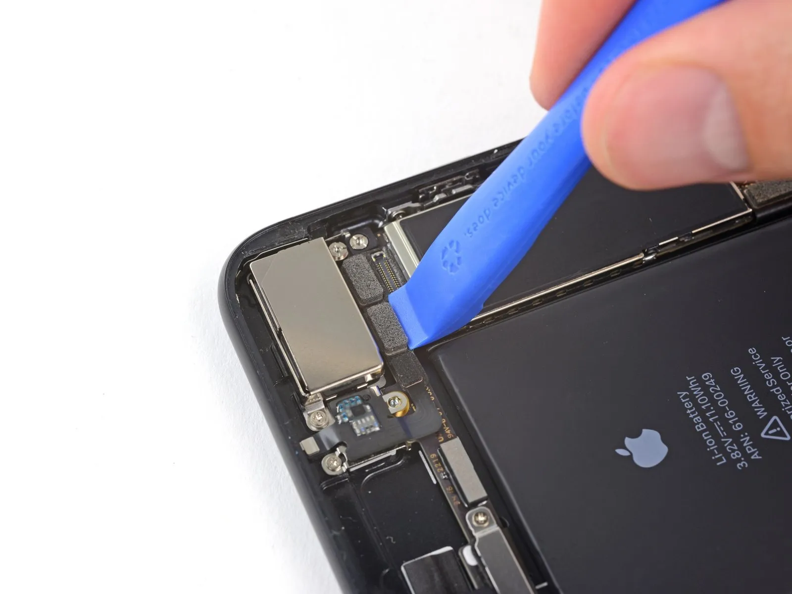


- To release the two camera cable connectors, employ an iFixit opening tool or a fingernail, carefully lifting them vertically away from their respective connection points.
Step 21


Employ the planar surface of a spudger toolto carefully lift the rear-facing camera component away from the iPhone's upper boundary.
Step 22

Carefully detach the rear camera module from the device.
Step 23 | Camera bottom bracket


Extracting this bottom bracket presents a significant challenge, as its inner circular edge appears to be affixed with a substance resembling the sealant used on camera lenses, necessitating considerable force and increasing the risk of complete bracket failure.
- My preferred method involves utilizing a flat screwdriver to insert into the assembly, carefully avoiding any contact with surrounding parts, and applying traction until audible cracking sounds are detected.
- These cracking sounds indicate the location of the adhesive bond, as visually confirmed in image three.
Step 24 | Final step


To conclude the repair, carefully extract the fractured camera lens from within the device.
- Initially, select a tool that provides comfortable control and requires minimal force to operate.
- Position your hands strategically to shield the rear casing from deformation during the repair process.
- Apply force to displace the camera lens, exercising extreme caution to prevent damage to both the phone and your hand.
Secure the replacement camera lens using adhesive or glue, ensuring a firm bond with both the lens itself and the new bottom bracket.
- Replacement of the bracket is optional; it is not a required step for this repair.
Should you be concerned about potential damage to the iPhone 7 Plus, consider seeking professional assistance at an Apple service center.
- My procedure involves stabilizing the phone on a flat surface, orienting the camera outwards, and positioning myflat screwdriverat the location indicated by the red marker, followed by a gentle tapping motion with a hammer.
Step 25 | Inserting a new camera lens

- For installation of a replacement, position the component on a flat surface and carefully lower the device onto it, applying gentle pressure to slide it into place.
- Confirm the new camera lens sits level with the rear housing before retracing the disassembly procedure.