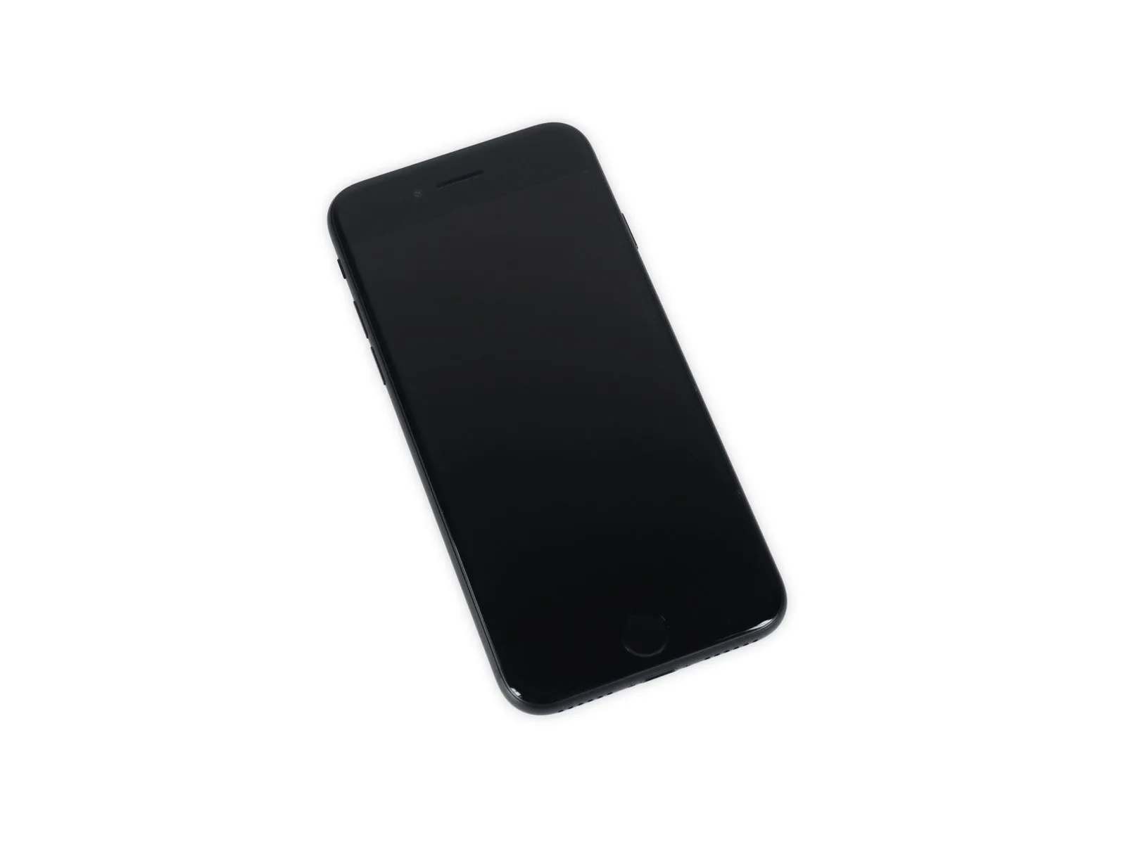
iPhone 7 Teardown
Following complete disassembly of the iPhone 7 Plus, this guide proceeds with the third step in our Tokyo teardown series. The device is missing one camera module and retains the original quantity of headphone jacks.Ensure the device is a 7 Plus model.We are pleased to present this guide.Apple iPhone 7Disassemble the unit.
- Exercise caution and adhere to safety protocols while performing this procedure.
- For ongoing support and updates throughout this repair process, connect with us on Facebook, Instagram, or Twitter.
Step 1 | iPhone 7 Teardown

- The device utilizes an Apple-designed A10 Fusion processor.Carefully position the 12mm wrench on the fastener and rotate it counterclockwise to loosen, ensuring you observe the safety warning regarding potential pinch points and wear appropriate hand protection.The system incorporates an M10 motion coprocessor.
- The device offers internal storage options of either 32, 128, or 256 gigabytes.
- The screen is a 4.7-inch Retina HD display utilizing IPS technology and supports multitouch input.The display resolution is 1334 by 750 pixels, equating to a pixel density of 326 pixels per inch.
- A 12-megapixel camera.The lens features an f/1.8 aperture, incorporates optical image stabilization technology, and provides a 5x digital zoom capability.
- A 7-megapixel FaceTime high-definition camera.The camera features a maximum aperture of f/2.2 and supports recording video in 1080p HD resolution.
- The home button utilizes a touch-sensitive interface, not physical moving parts.The device now incorporates a redesigned Taptic Engine.
- The device incorporates 802.11a, 802.11b, 802.11g, 802.11n, and 802.11ac Wi-Fi connectivity alongside MIMO Bluetooth version 4.2 and NFC functionality.
Step 2

- The screen utilizes an IPS panel with LED backlighting and has a resolution of 1334 pixels by 750 pixels.The display offers a wider P3 color range and delivers 25% greater brightness compared to the 6s model.
- The camera features a 12-megapixel image sensor and a maximum aperture of f/1.8.The integrated optical image stabilization system offers a 60% performance increase and 30% greater power efficiency compared to the prior model.
- Four LEDs provide True Tone illumination.The display's luminance is 50% greater than that of an iPhone 6s.
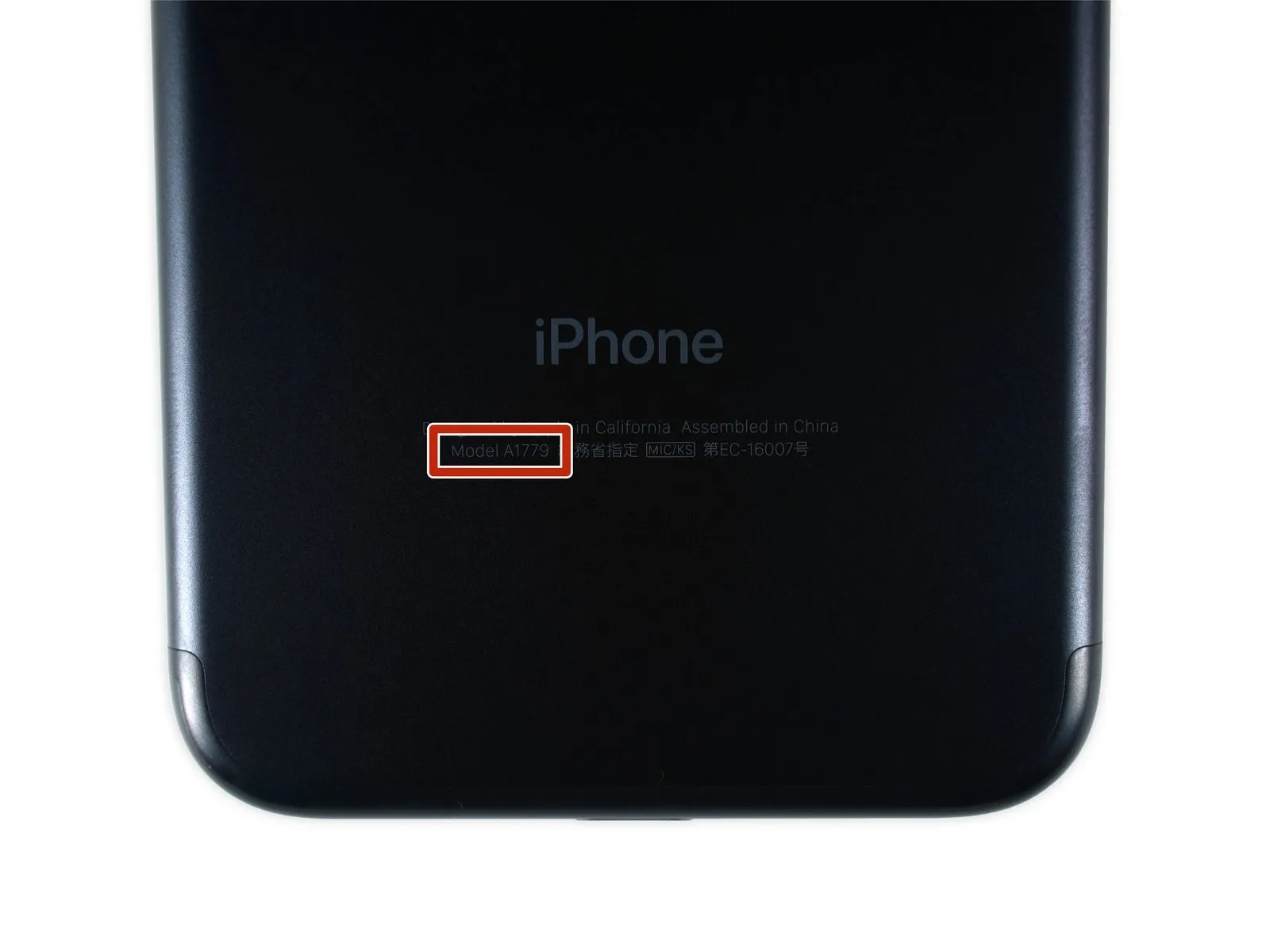
- The rear case bears a newly applied model identifier: A1779.
Step 3
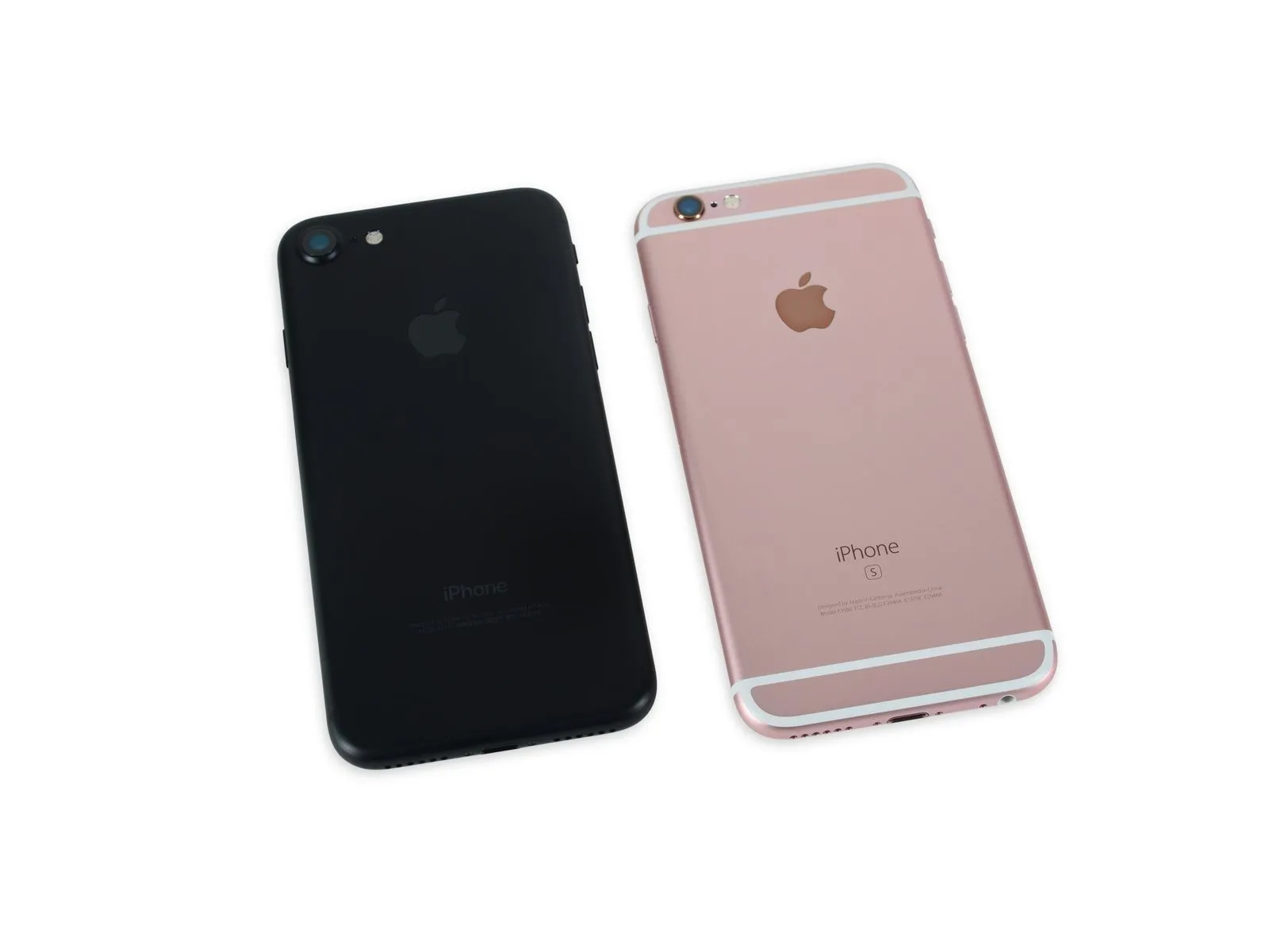
- At 138.3 mm x 67.1 mm x 7.1 mm, the iPhone 7's physical size is identical to the iPhone 6s, although it weighs slightly less.The component's weight is 138 grams.When making a comparison, use the following values.The required mass is 143 grams.Regarding the iPhone 6s,
- The observed weight variation is five grams, equivalent to the mass of roughly two U.S. pennies; this discrepancy is significant only if it impacts ease of repair, a consideration we acknowledge with a touch of irony.
- The iPhone 7’s design incorporates a more subtle appearance for the antenna lines, unlike previous models, however, the camera housing remains prominently raised.
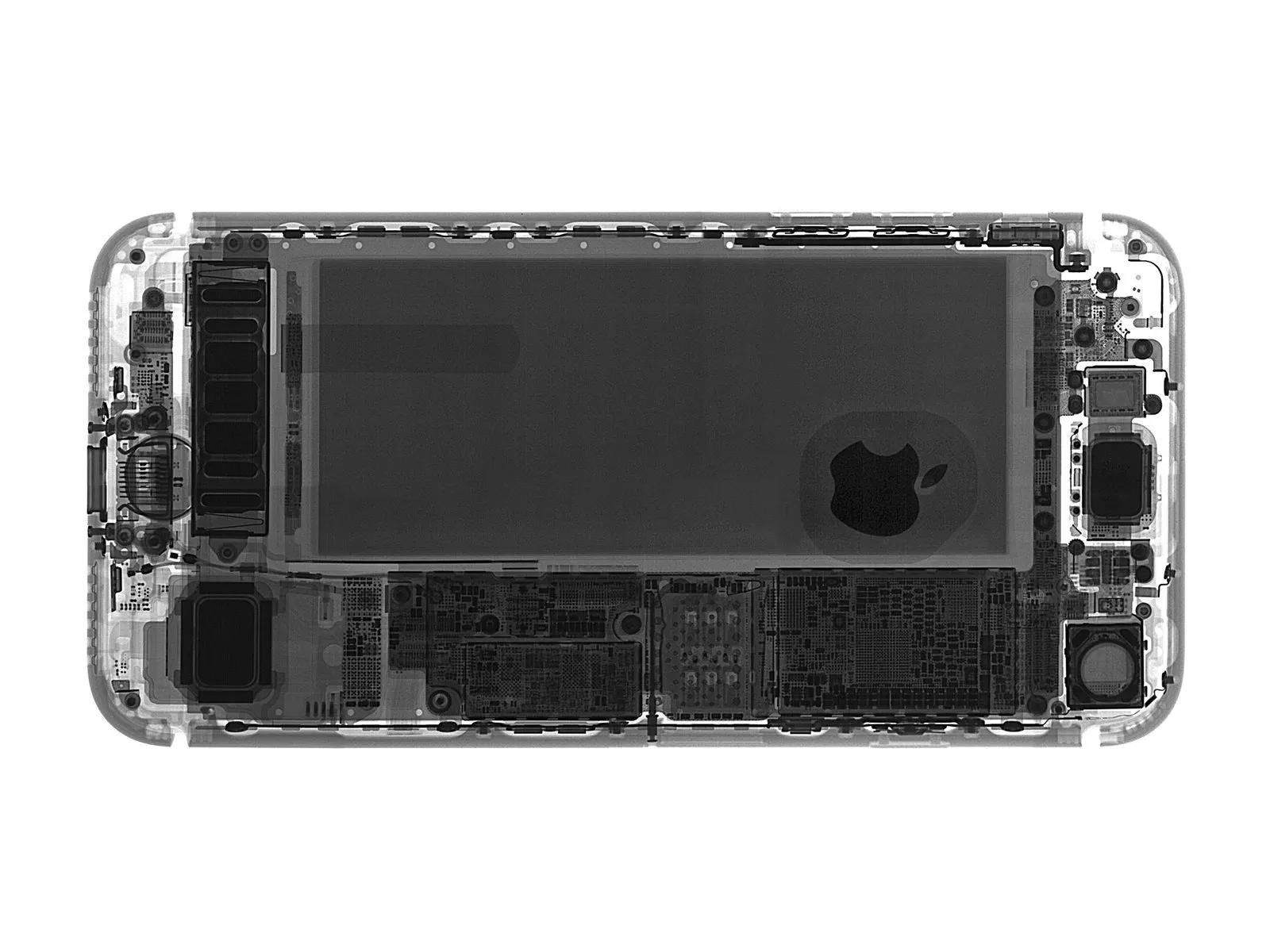
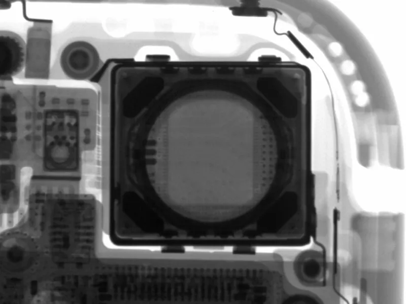
- Using X-ray imaging, Creative Electron has allowed us to examine the internal components of this unit, providing a detailed view of the assembly.
Step 4
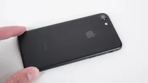
- The iPhone 7 is available in several color options, including matte black, gold, rose gold, jet black, or silver.
- Be aware that the jet black coating is particularly susceptible to scratches, which are difficult to repair.
Step 5
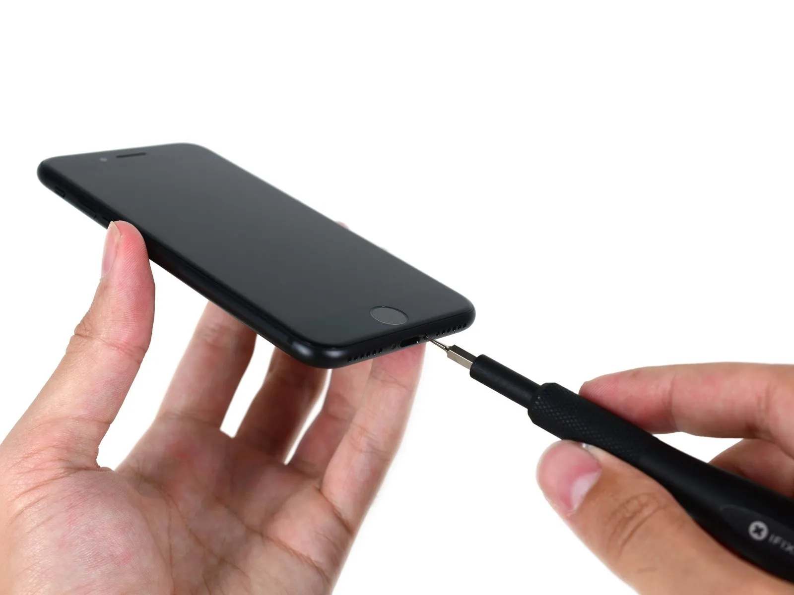
- Carefully detach the two Pentalobe screws, which are unique to this device, using a Pentalobe screwdriver.
- This technician demonstrates a high level of skill in performing repairs.
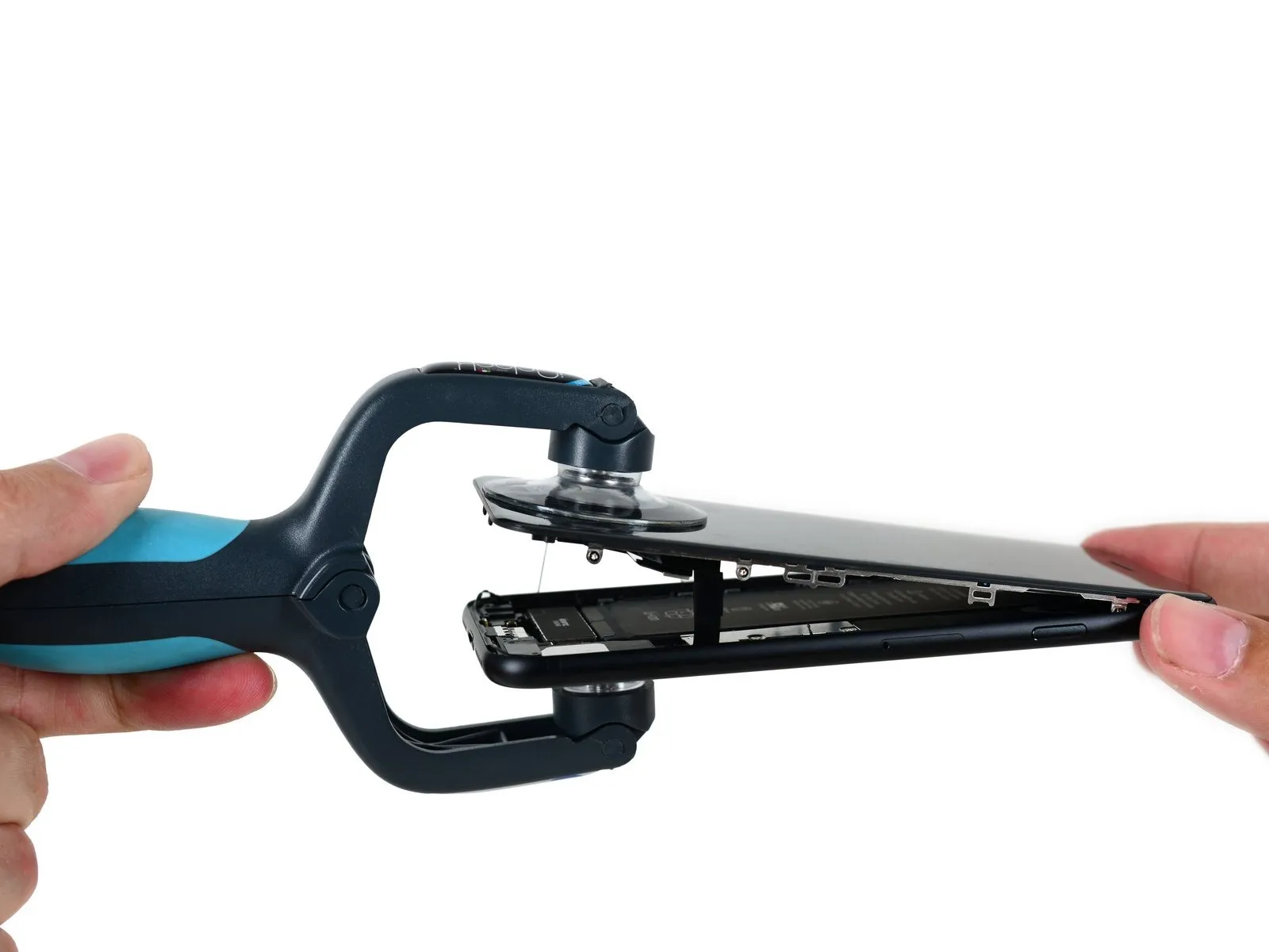
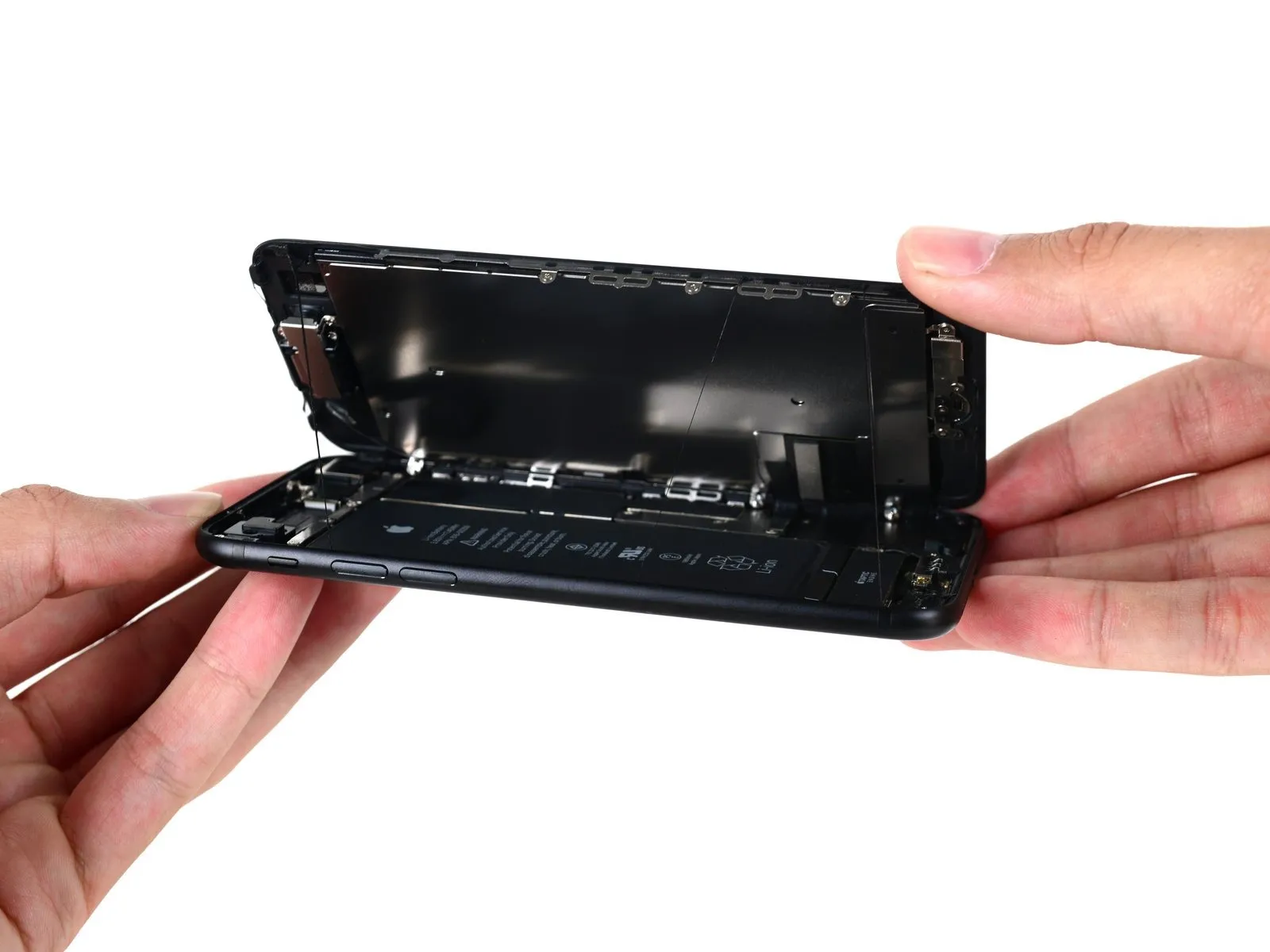
- Using the iSclack tool, carefully create a small gap, ensuring no damage occurs to the iPhone's casing.
- Unlike earlier iPhone models, the iPhone 7’s display assembly separates from the casing by sliding it laterally along the device’s side, and the internal connectors appear undamaged, suggesting a successful repair.
- Before drawing any conclusions, a comprehensive examination of the device will commence, beginning with the battery compartment.
Step 6
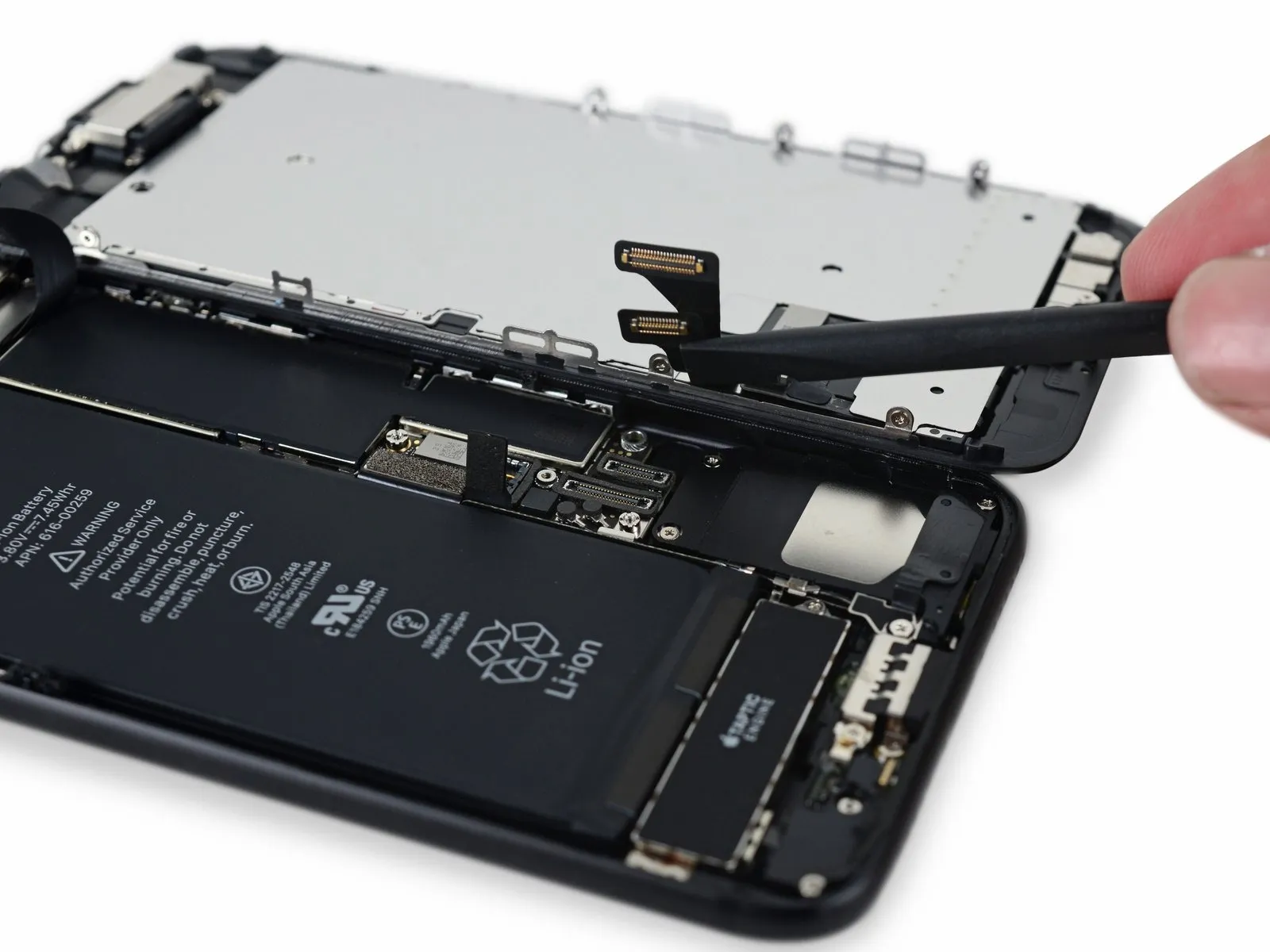
- Carefully separate the case halves, noting the adhesive sealant; you will encounter small tri-point screws that fasten the cable bracket, a design element also found in the larger iPhone 7 Plus.
- The specialized driver needed for battery replacement in your iPhone is already part of the included 64-bit toolkit, eliminating any sourcing concerns.
- After removing the front panel and adhesive strips, use a spudger to carefully disconnect the battery, then employ the same tool to release the display connectors.
Step 7
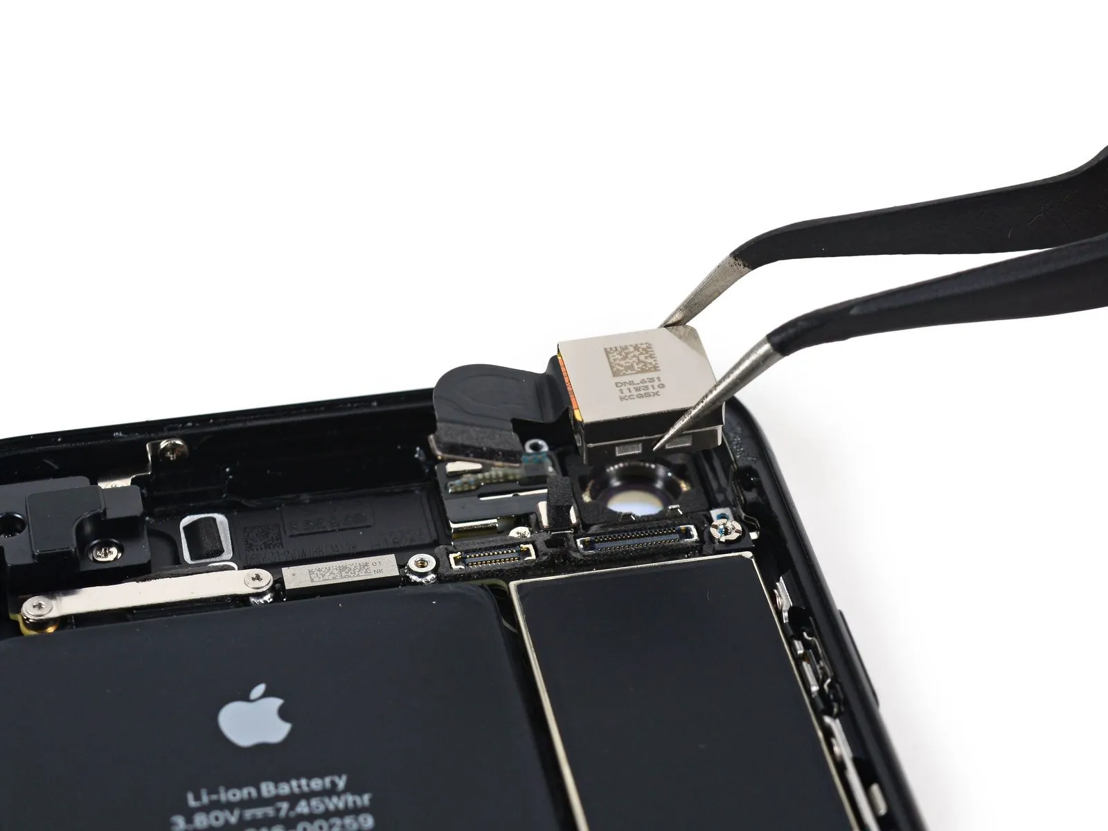
- Initiate the system by activating the illumination source, positioning the recording device, and commencing the operational sequence.
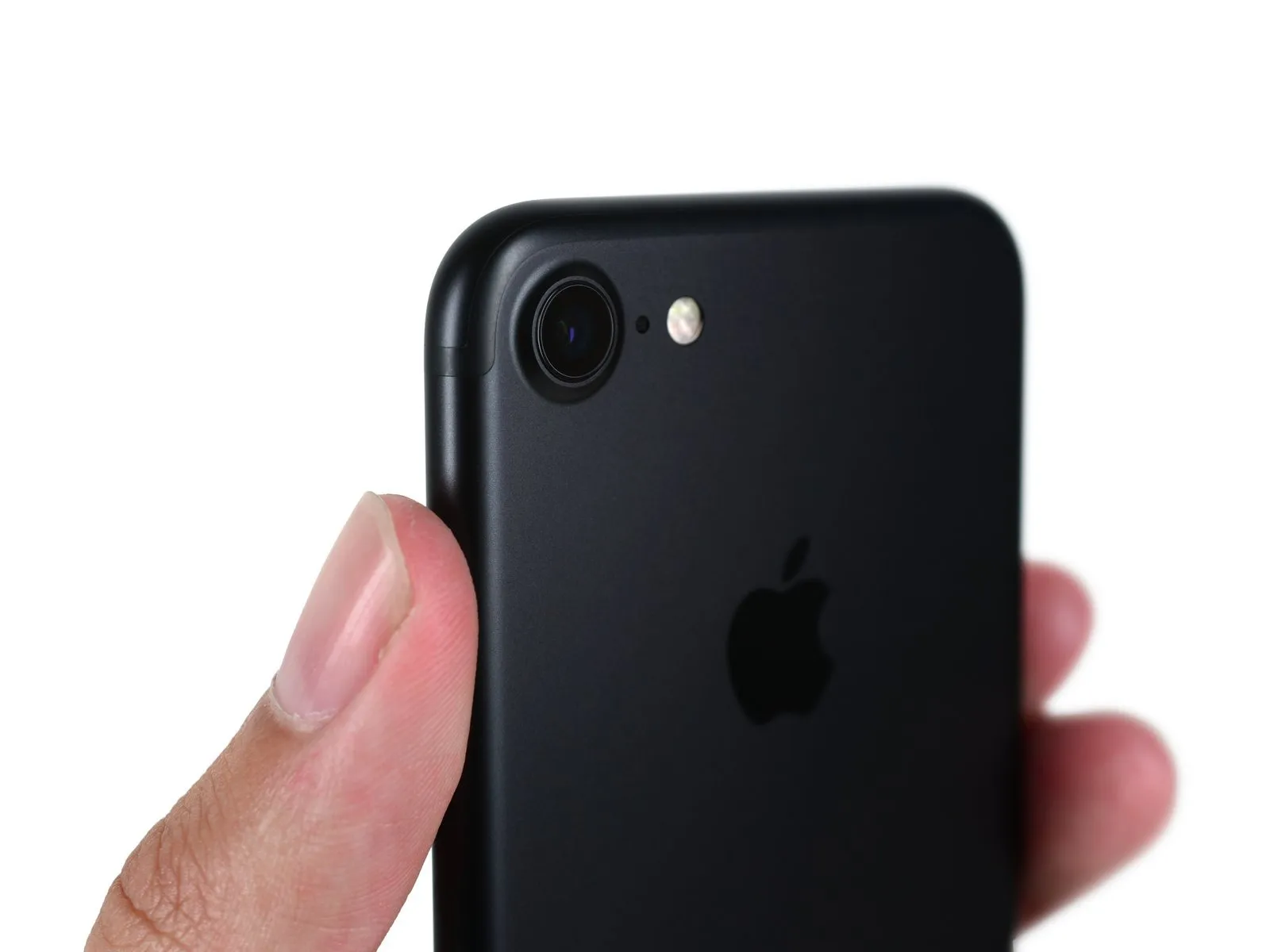
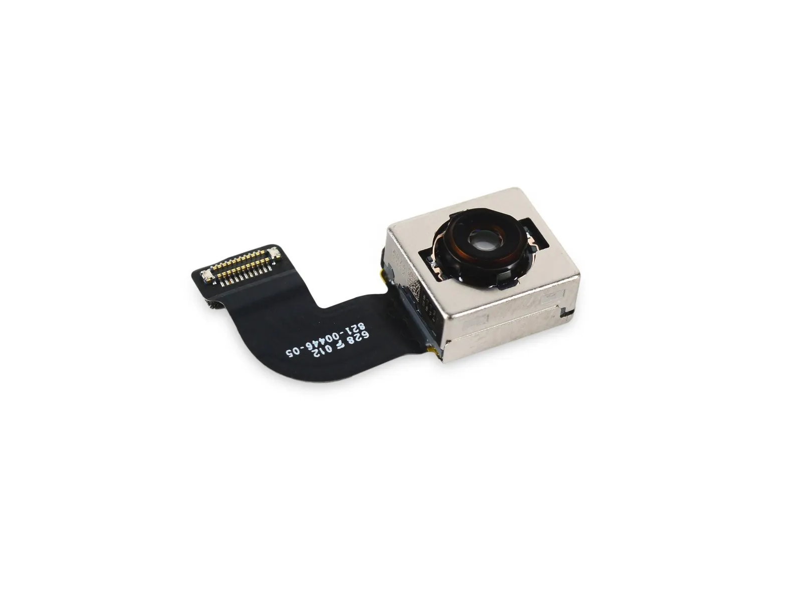
- The iPhone 7's camera system incorporates a 12 MP sensor, a new 6-element lens design, an f/1.8 aperture, four LEDs, and a flicker sensor to automatically adjust for fluctuating light sources in both photos and videos.
- This camera features a visually striking design.
- X-ray imaging confirms the camera's pristine condition both externally and internally.
- The device shares a strikingly similar external design to a previously encountered camera model.
Step 8
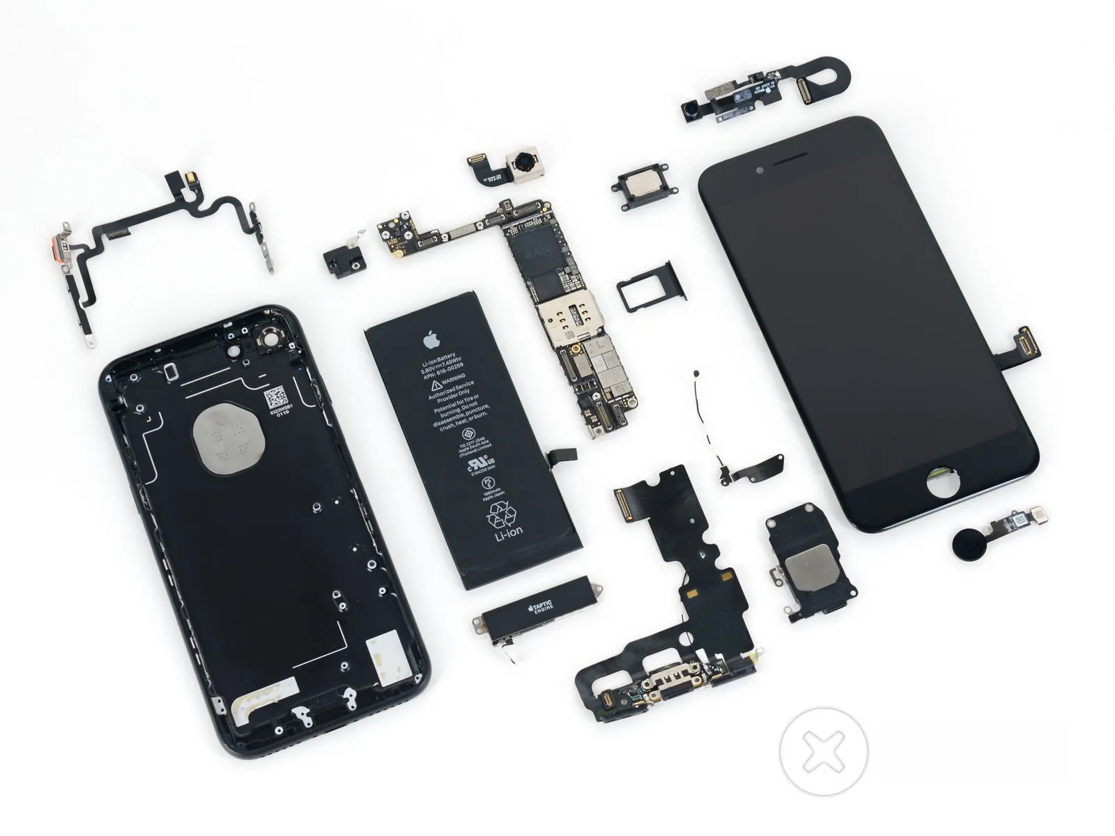
- After removing the camera assembly, proceed with disassembly of the 7.
- Carefully remove the audio baffle, which functions as a headphone jack, ensuring no damage occurs.
- Disassembly of the unit is now underway.Apple designates this plastic piece as a barometric vent, and its function is to allow pressure equalization between the iPhone's interior and the surrounding atmosphere, ensuring accurate altimeter readings thanks to the watertight seal's added protection.
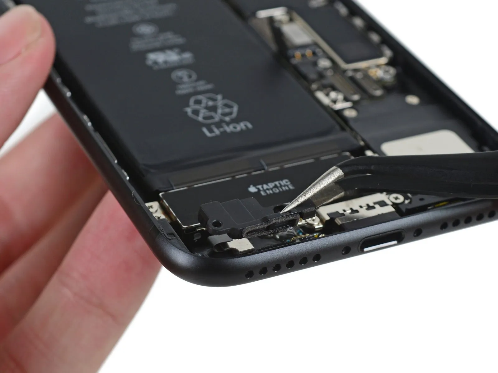
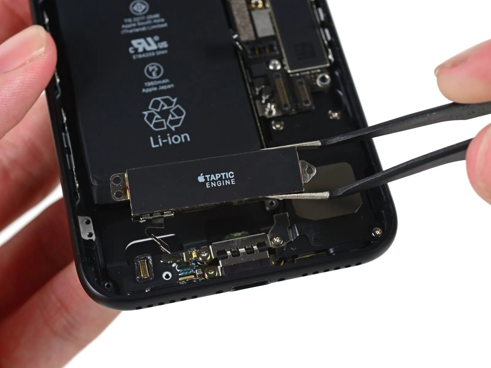
- To fulfill its function of providing haptic feedback for the home button, the Taptic Engine’s dimensions are larger than standard.
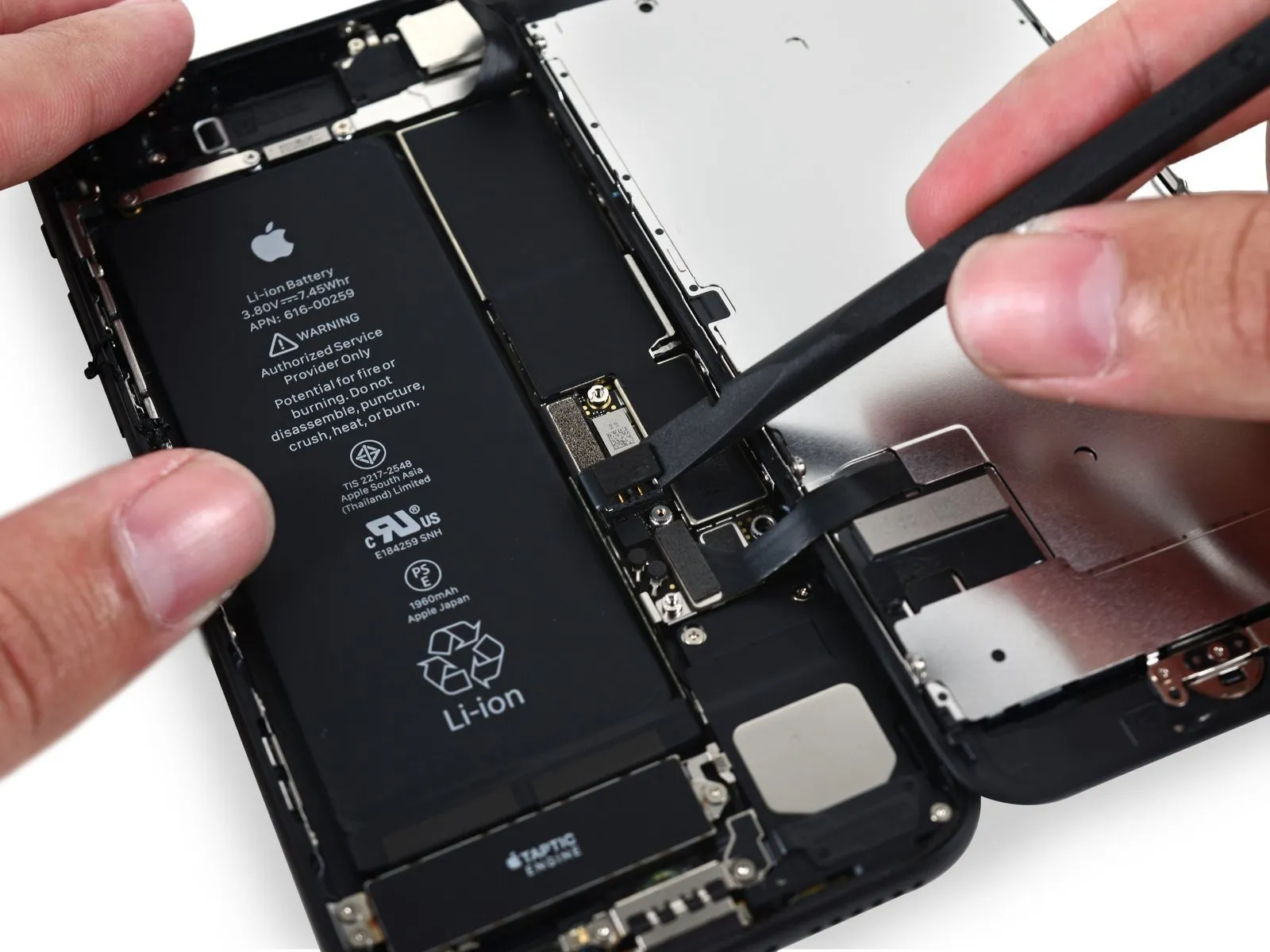
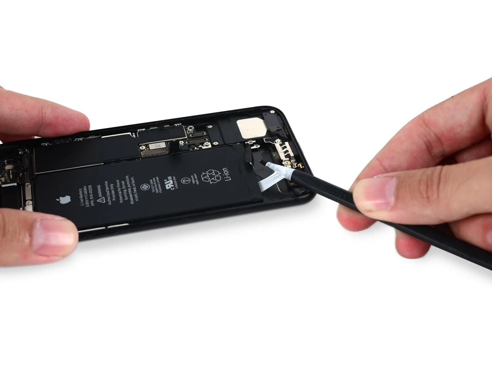
- After ensuring the surrounding area is free of obstructions, carefully use a spudger to detach the adhesive securing the battery. Then, gently wind and extract the three battery pull tabs.
Step 9
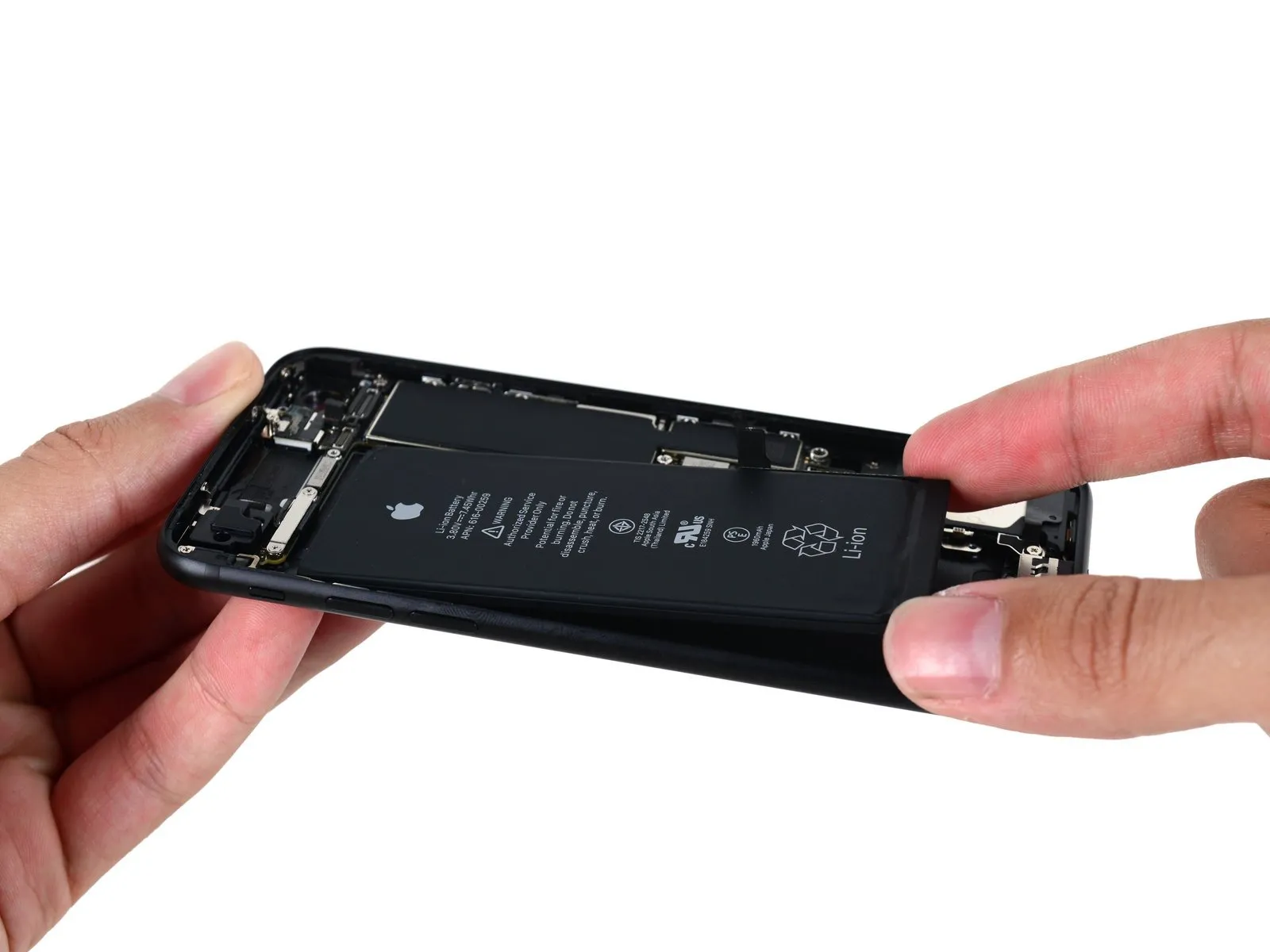
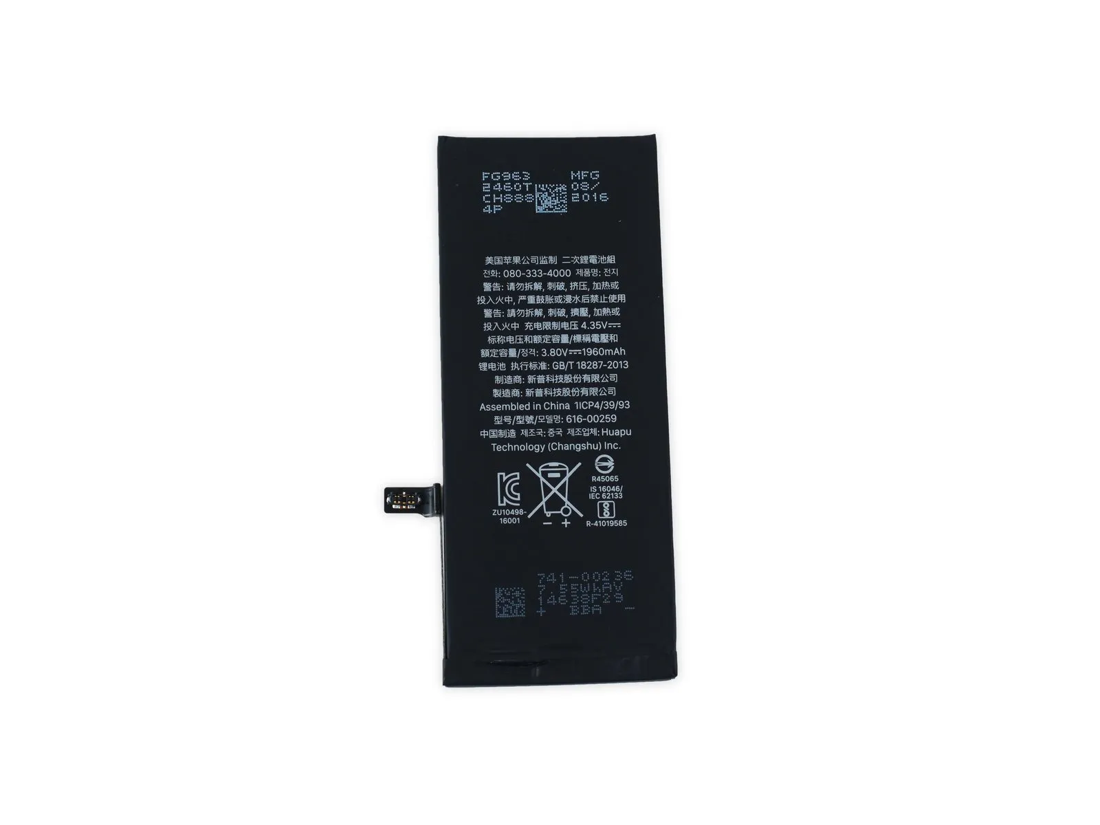
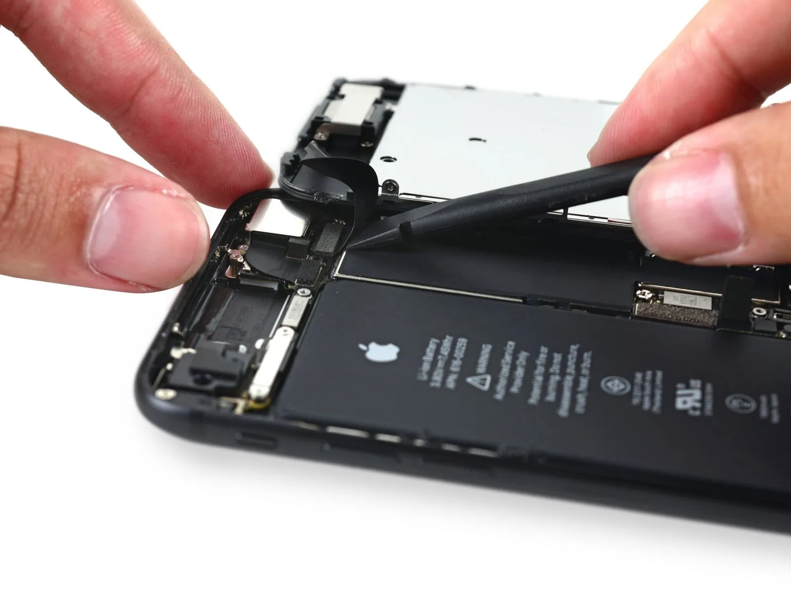
- The iPhone 7's battery is now accessible, the device's power supply.
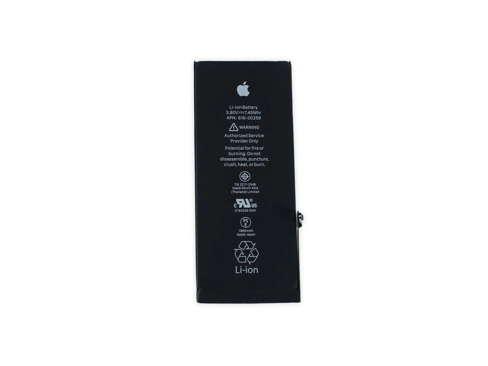
- The battery is a standard Lithium-ion type, presenting a low risk during repair procedures.The required voltage is 3.8 volts.,The battery capacity is 1960 milliampere-hours.The battery's specified power storage isThe energy content is 7.45 watt-hours.A significant rise is observed.The energy content is 6.55 watt-hours.Replace the battery in the previous year's version.
- According to Apple, the enhanced battery offers a maximum operational duration of up toThe estimated completion time for this procedure is 14 hours.lasting for three generations of voice communication.The estimated completion time for this task is 14 hours.To access the internet via Wi-FiAllow a minimum of ten days for this process to complete.Ensure the device consumes no more than 0.5 watts during standby mode.
- This battery’s extended operational duration is a positive attribute; however, the retention of easily accessible pull tabs for replacement procedures and the absence of any catastrophic failure events are particularly noteworthy features.
Step 10
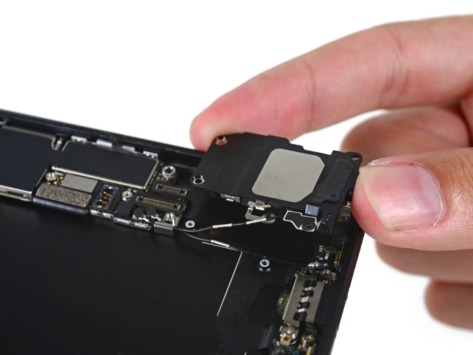
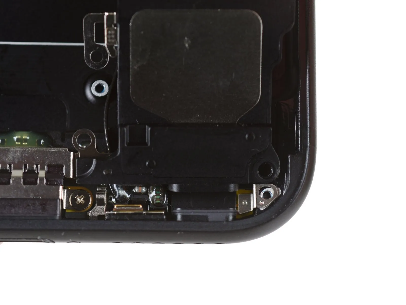
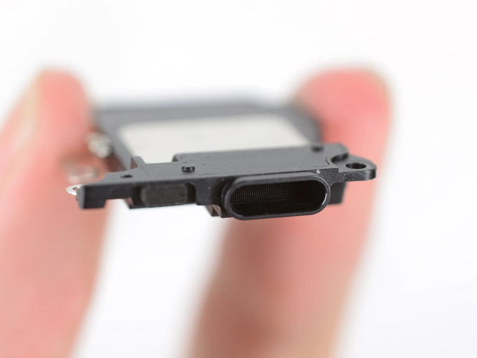
- The iPhone 7's speaker assembly includes an adhesive Wi-Fi diversity antenna, secured with a leash, which connects to the logic board.
- Be aware that maintaining the device's water resistance requires careful handling and adherence to all manufacturer guidelines.To enhance protection against foreign matter, the speaker's output duct is designed to overlap a rubber speaker grille gasket.
- The internal architecture closely mirrors the design found in the iPhone 7 Plus, as observed during a recent examination.
- To provide an additional layer of protection against water ingress, a fine mesh is integrated into the duct.
Step 11
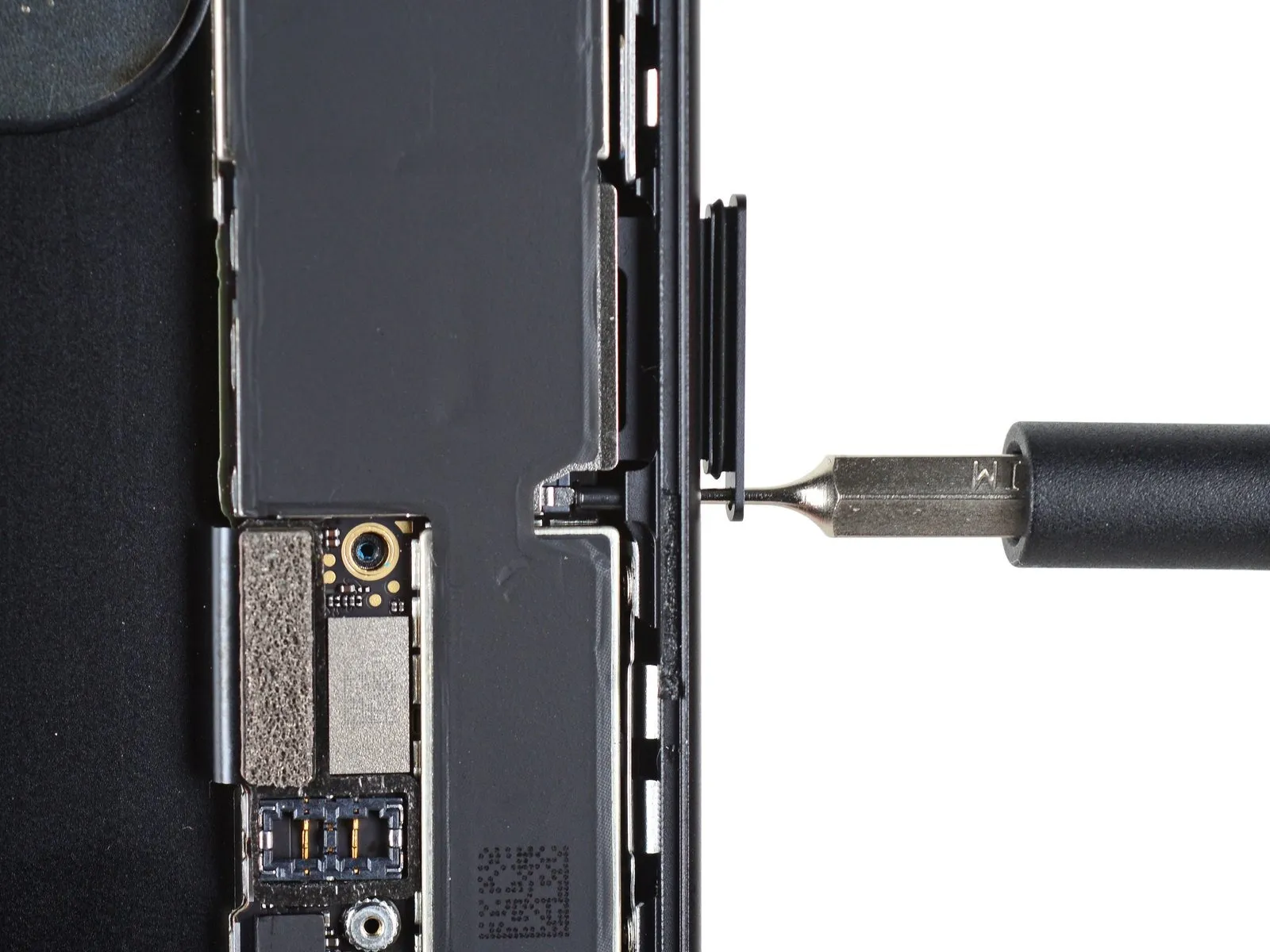
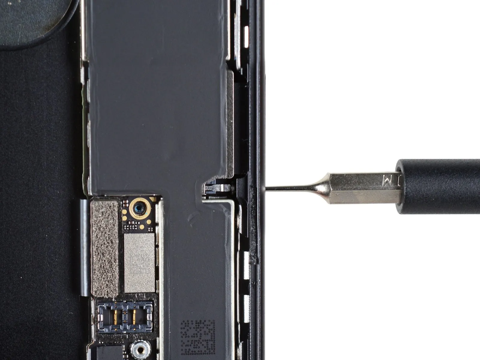
The SIM tray is released via a complex mechanical linkage; applying pressure with the SIM eject tool depresses a plastic pin, which then transmits force to a metal pin, ultimately causing the SIM tray to pop out.
This additional measure provides a further safeguard against accidental drops into the toilet bowl.
Apple also incorporated a rubber gasket to seal the SIM tray.
Step 12
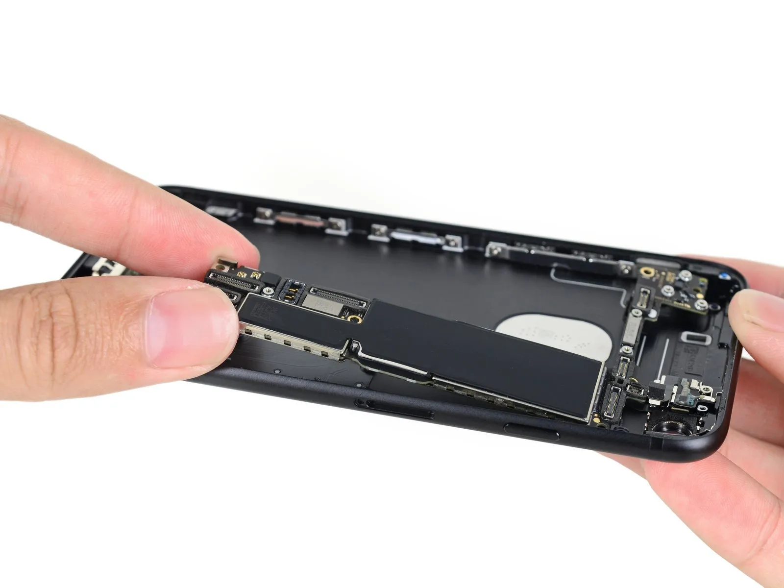
To facilitate a detailed inspection of the integrated circuits, detach the logic board promptly.
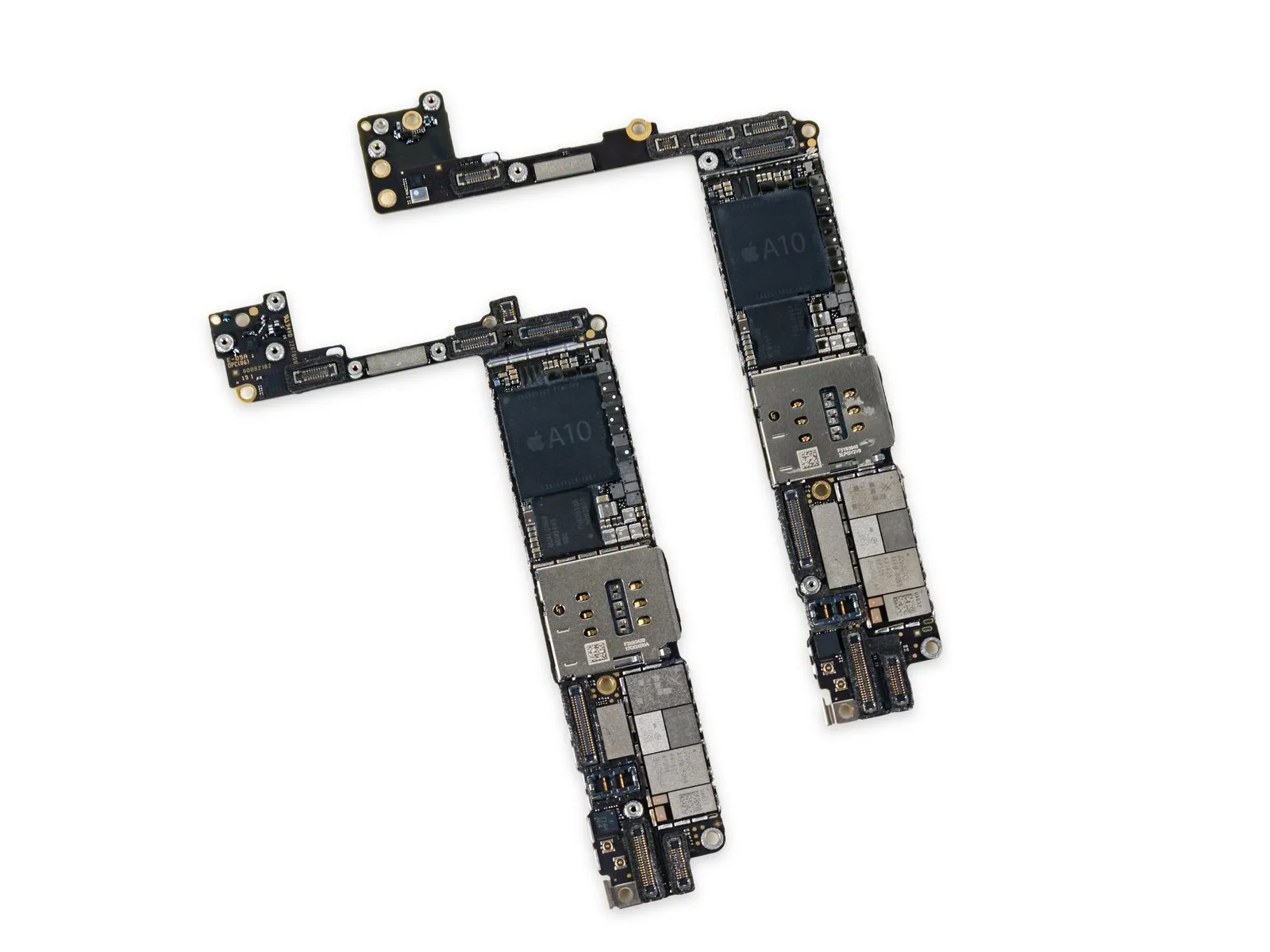
Before proceeding, examine the iPhone 7 Plus logic board alongside the one you are working on to observe their similarities, recognizing that while the housings differ in size, the boards themselves share a comparable design.
Carefully observe that connector dimensions and positions, along with the placement of post holes and screws, exhibit slight variations.
Despite the familiar design, adjustments were necessary to accommodate the specific requirements of the iPhone 7 Plus's internal components and circuitry.
Step 13
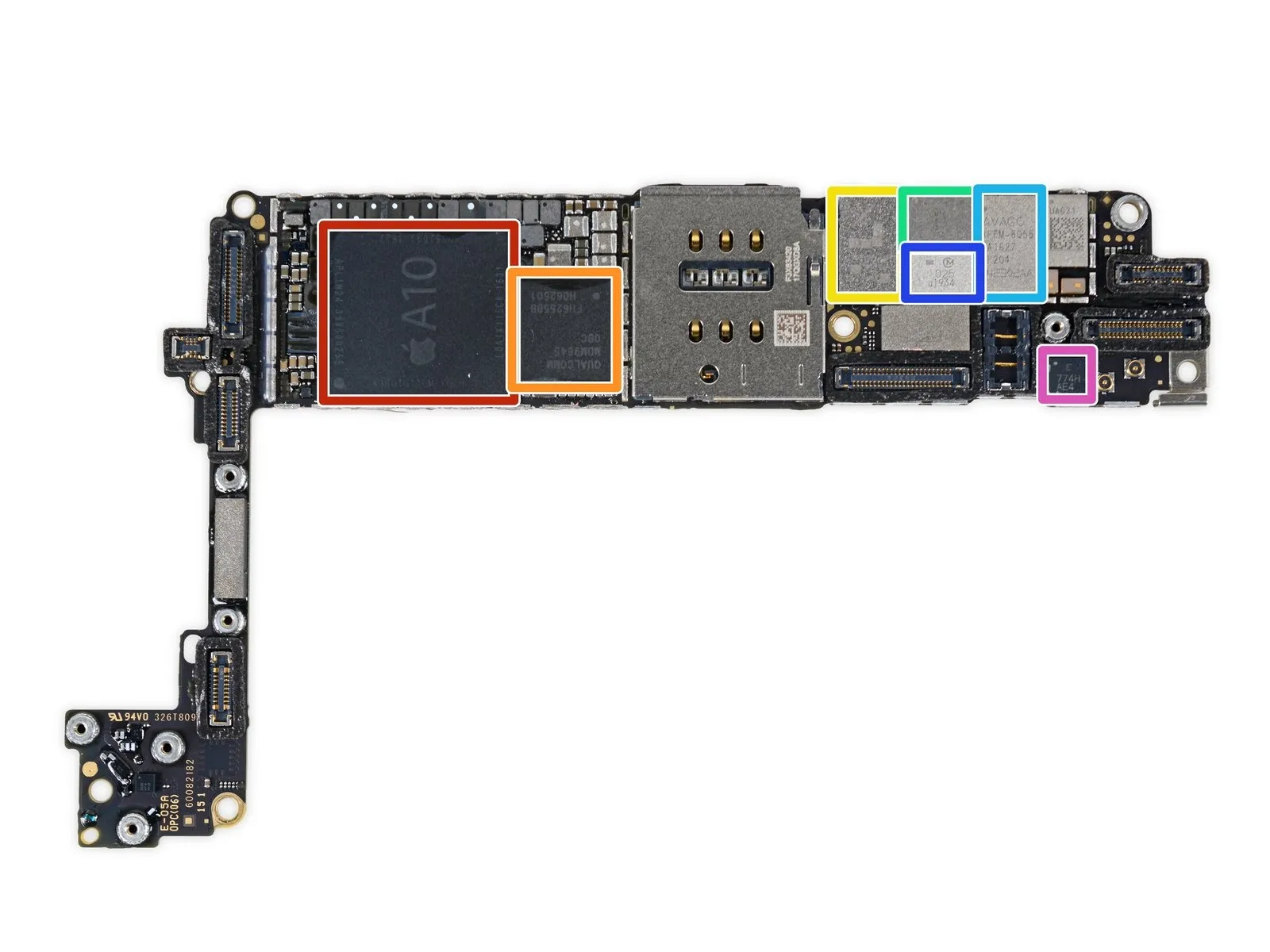
Expect to find a significant amount of silicone sealant during disassembly; the logic board contains numerous applications.
- The APL1W24 SoC, which is an Apple A10 Fusion processor.+The memory module is a 2 GB LPDDR4 type, identifiable by the part number K3RG1G10CM-YGCH.
- LTE Cat. 12 Modem, Qualcomm MDM9645M.
- The Power Amplifier Module is a Skyworks SKY78100-20.
- Avago's AFEM-8065 is a power amplifier module.
- Avago's AFEM-8055 is a power amplifier module.
- The antenna switch module, probably a Murata 025 component, is present.
- Utilize an Invensense accelerometer.
Step 14
Conversely, proceed with the same steps in reverse order.
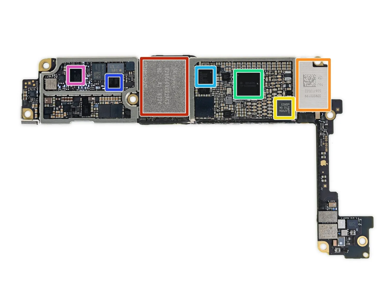
- A 32 GB SK Hynix H23QEG8VG2ACS flash memory component.
- Wi-Fi and Bluetooth functionality is provided by the Murata 339S00199 module.
- The NFC Controller with Secure Element is an NXP PN67V component.
- Power management integrated circuit, identified as Apple/Dialog Semiconductor 338S00225.
- The device incorporates a Qualcomm PMD9645 integrated circuit for power management.
- The Qualcomm WTR4905 is a multimode LTE transceiver.
- RF transceiver: Qualcomm WTR3925.
Step 15
Additional integrated circuits are required.
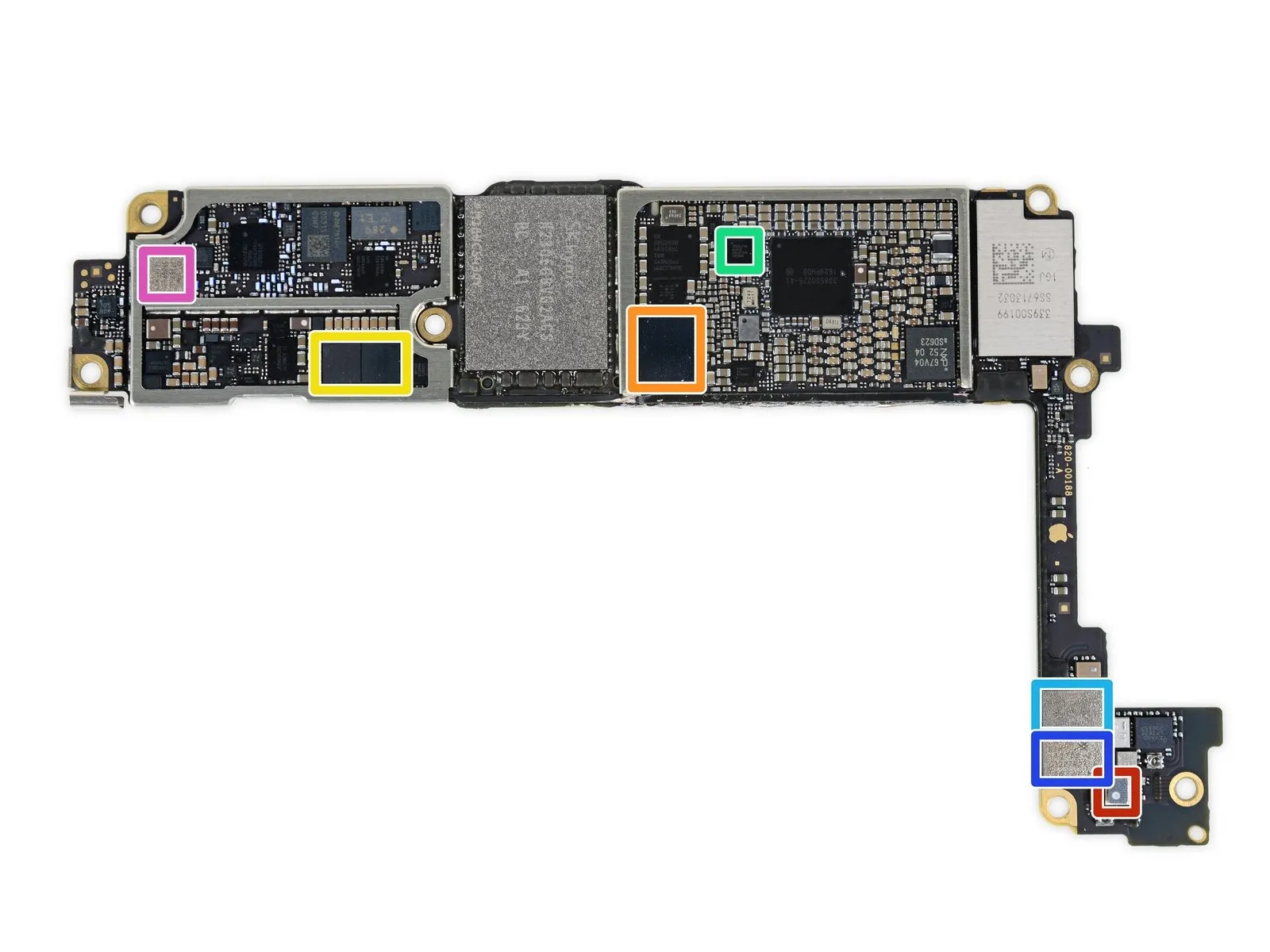
- The BMP280 is a barometric pressure sensor manufactured by Bosch Sensortec.
- The audio codec is a Cirrus Logic 338S00105 component used by Apple.
- Two Cirrus Logic 338S00220 audio amplifiers are present.
- Utilize a Lattice Semiconductor ICE5LP4K or iCE40 FPGA.
- The Skyworks SKY13702-20 serves as a diversity receiver module.
- Diversity Receive Module, Skyworks SKY13703-21.
- A Skyworks SKY77363-11 amplifier, presumably present.
Step 16

Only a small number of integrated circuits are still present.
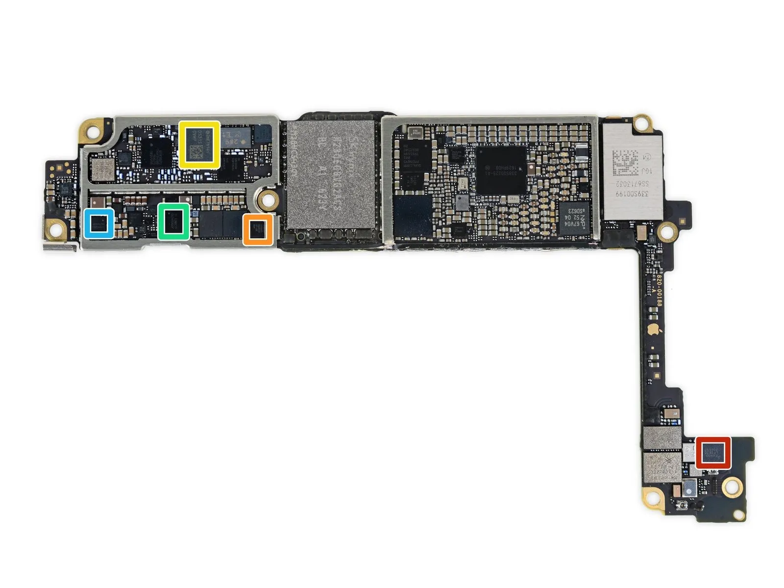
- Avago part number LFI626, 200157.Using a screwdriver, carefully adjust the capacitor until the SWR meter indicates a minimum value, ensuring the reading remains below 2.0:1 and never exceeds 3.0:1, while monitoring the inductance setting; if necessary, fine-tune the inductance with its dedicated adjustment knob to achieve optimal matching, always observing the SWR meter throughout the process and avoiding values above 3.0:1 to prevent potential damage to the transmitter.
- The CBTL1610A3 is a Display Port multiplexer manufactured by NXP Semiconductor.Please provide the original text you want me to rewrite. I'm ready when you are!
- The module is a TDK EPCOS D5315 Antenna Switch.Please provide the original text you want me to rewrite. I'm ready when you are!
- The integrated circuit designated SN2400AB0 functions as a battery charger from Texas Instruments.Please provide the original text you want me to rewrite. I'm ready when you are!
- The power management integrated circuit is a Texas Instruments TPS65730A0P.
- The DC-DC converter is a Texas Instruments SN61200.Please provide the original text you want me to rewrite. I'm ready when you are!
Step 17
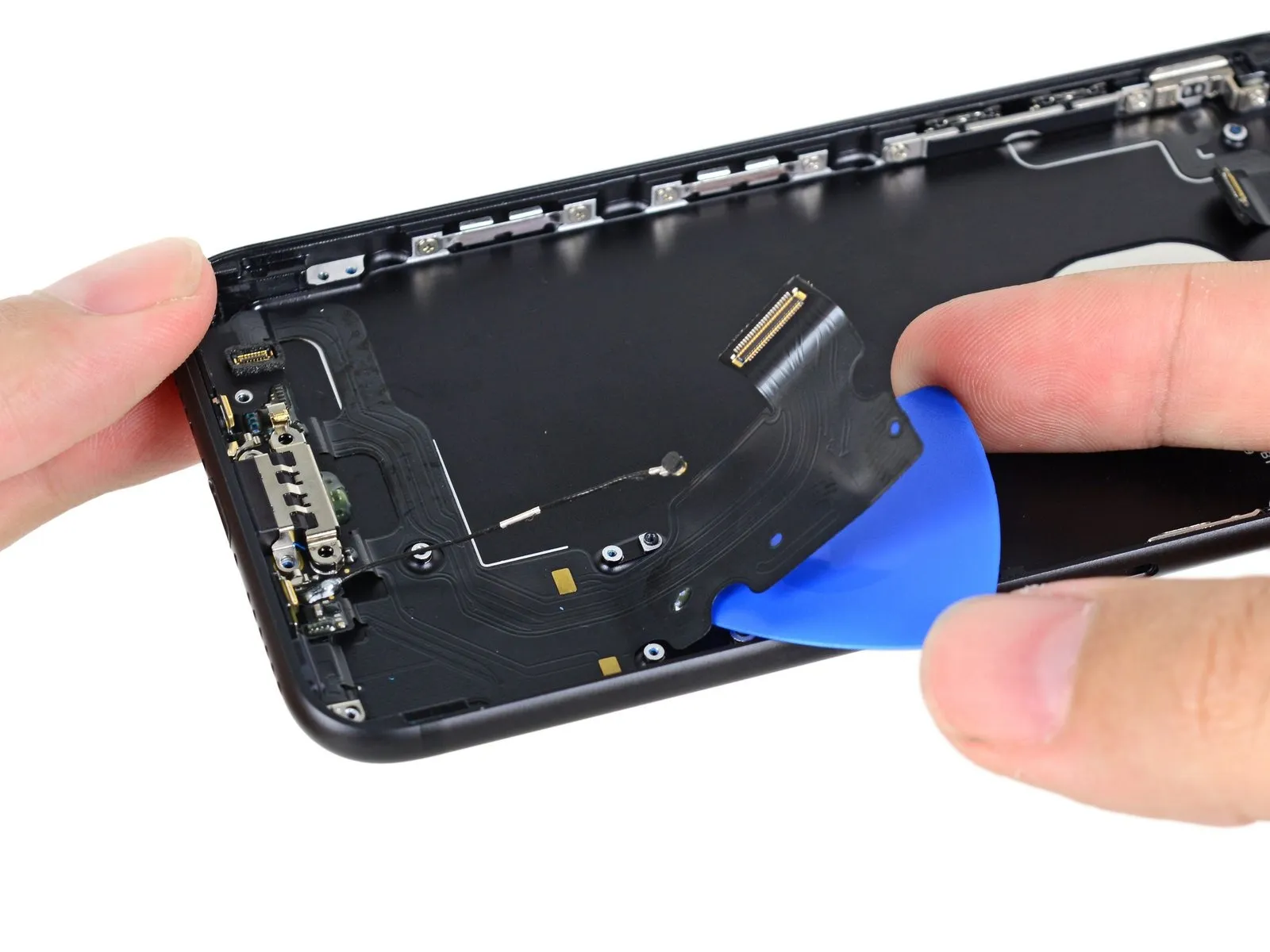
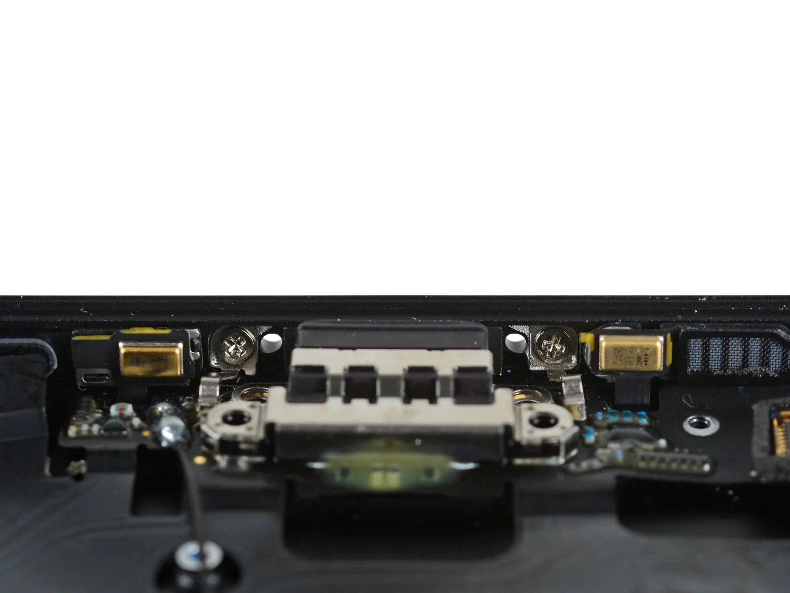
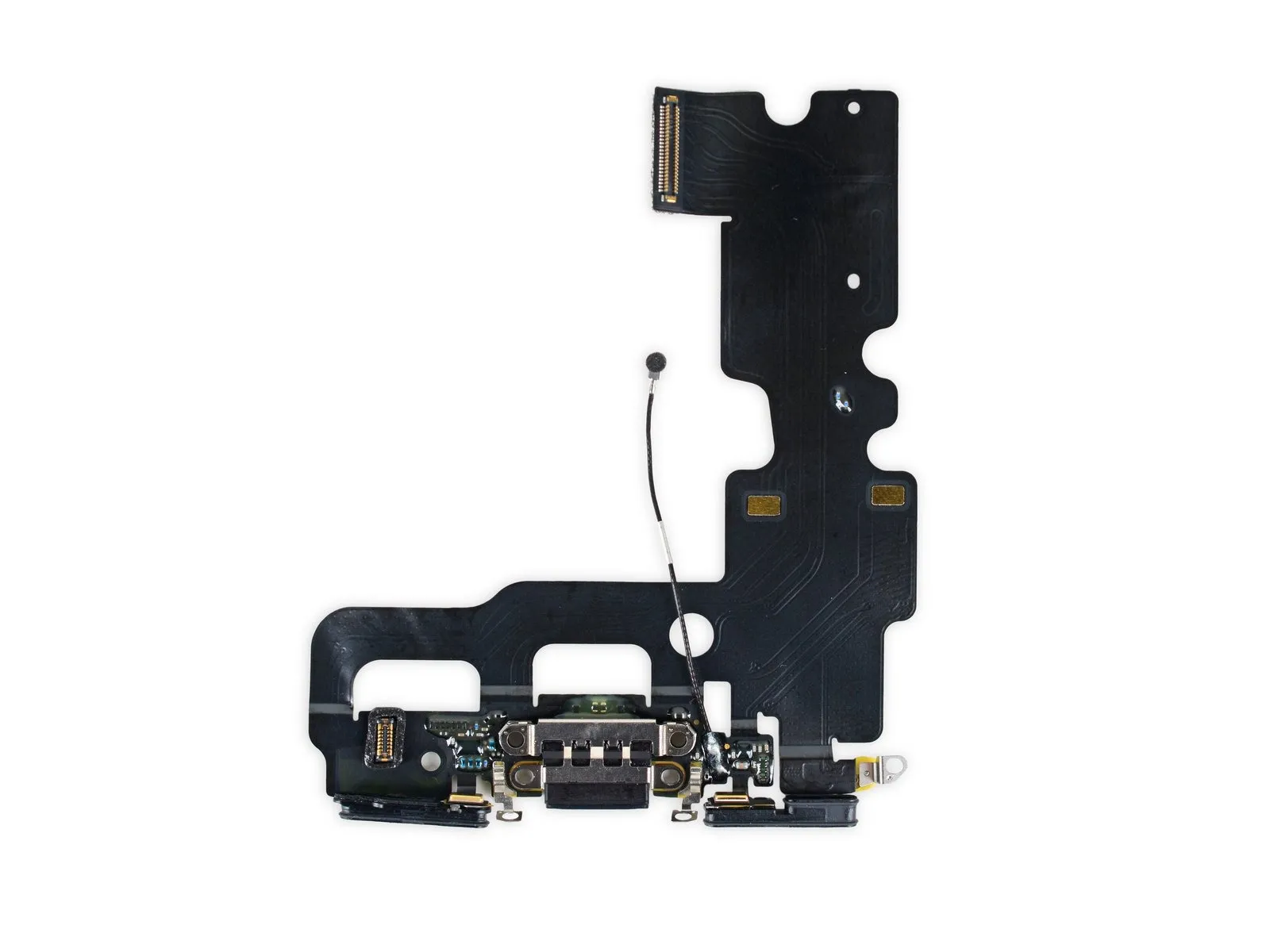
- With the logic board removed, proceed to locate and detach the Lightning connector assembly.
- Despite the successful separation of the adhesive, the initial attempt to detach the component failed; examine the port for additional screws securing it in place.
- Because the absence of a headphone jack shifts all audio responsibilities to this port, Apple has significantly strengthened its construction to withstand the increased usage and potential for damage.
- The Lightning cable also incorporates an antenna, two microphones, two speaker grille connectors, and the Lightning port itself.
Step 18
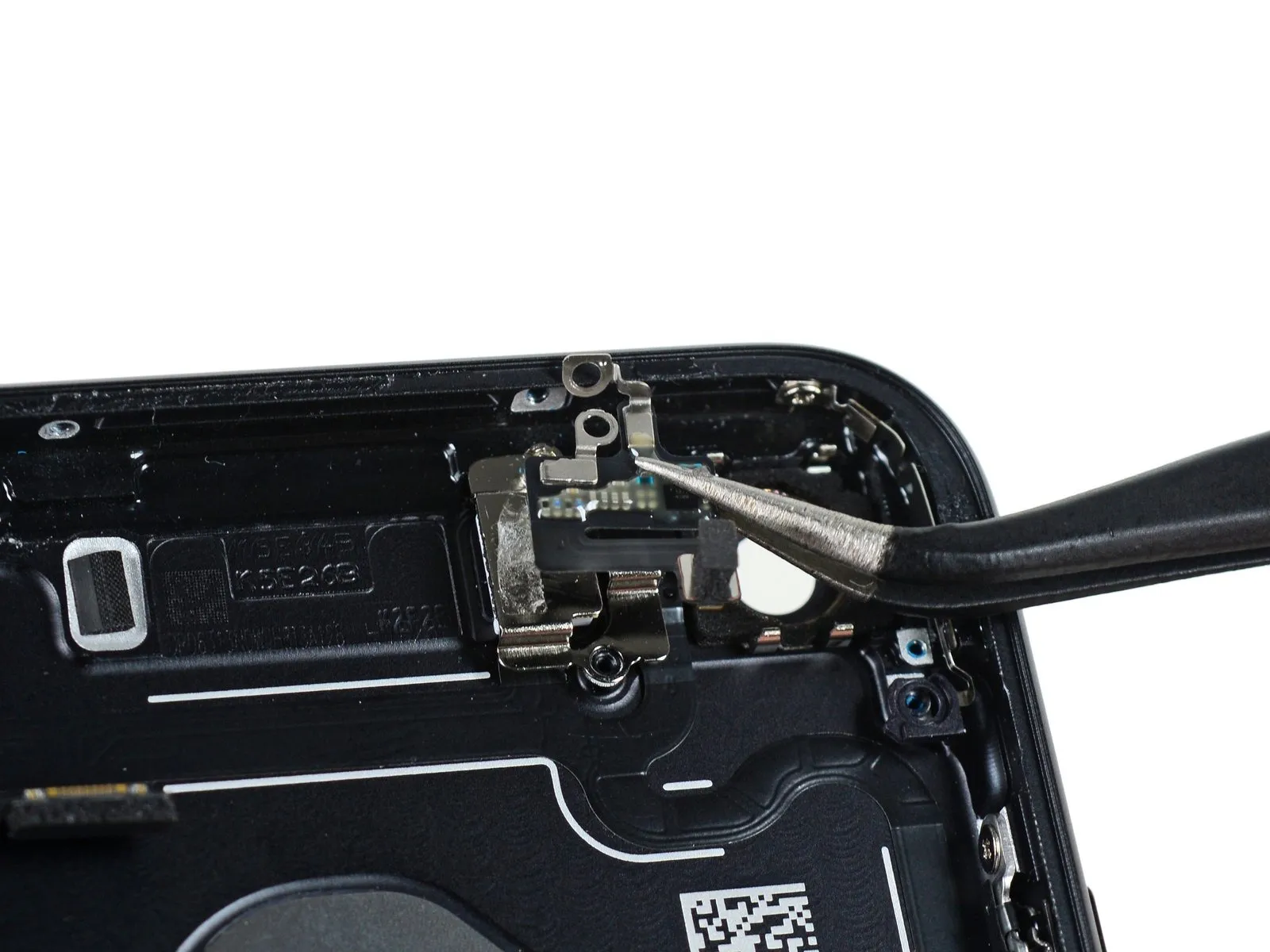
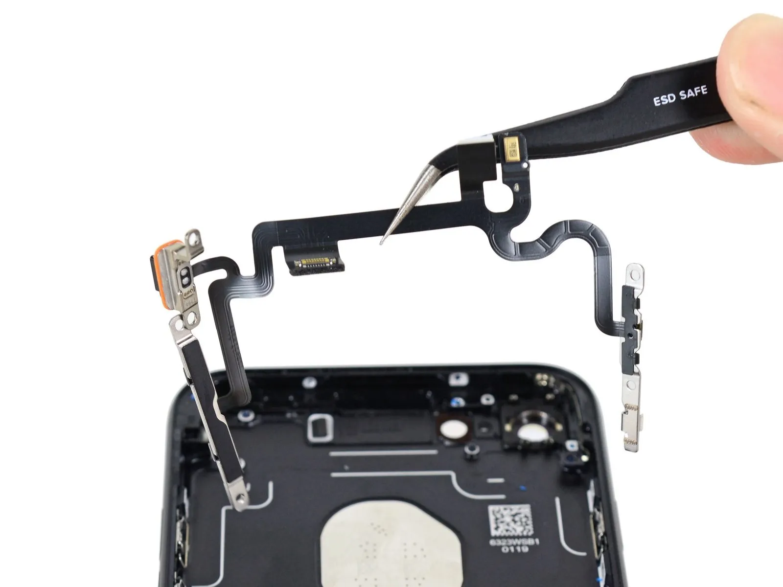
- Carefully remove any remaining debris from the phone case’s interior; doing so may reveal a damaged antenna flex cable.
- These delicate, thin button cables are prone to damage during removal and are situated amongst several waterproofed parts, making careful handling essential; avoid unnecessary disassembly of this connected assembly.
Step 19
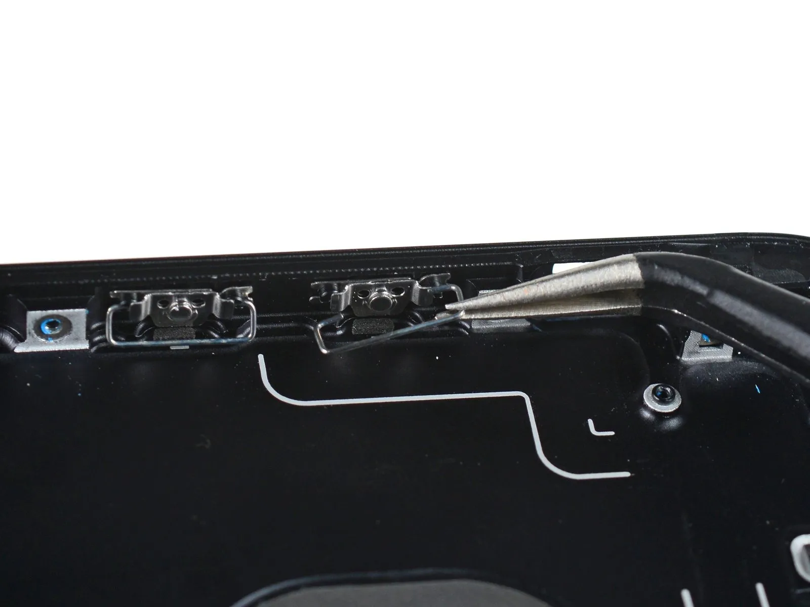
- Having mostly removed the rear cover, proceed to address the volume buttons, which presented difficulties during earlier disassembly of the 7 Plus model.
- Carefully use tweezers to gently dislodge the retaining flap, as forceful pulling may cause it to break; the button cover remains firmly attached.
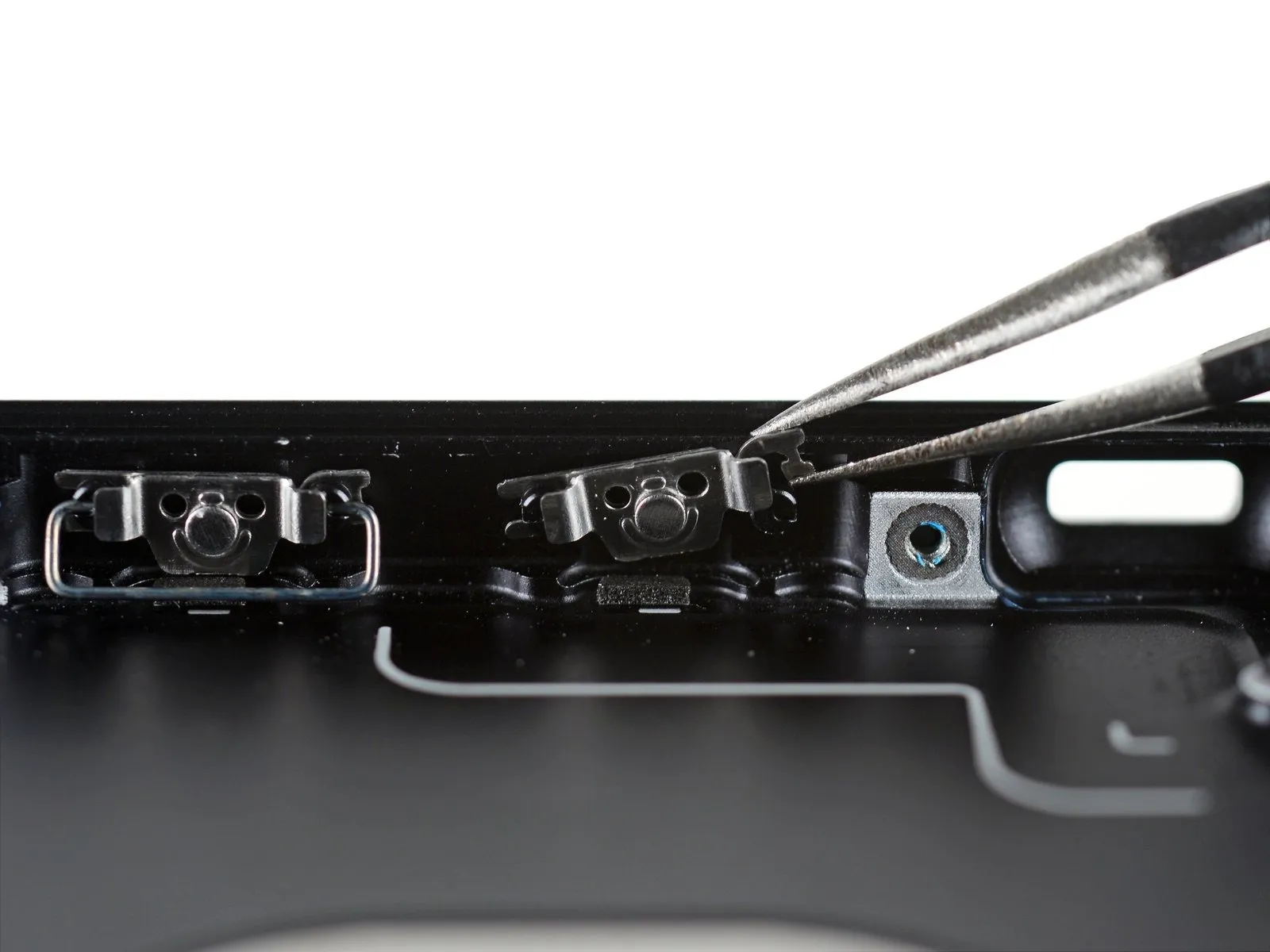
- Carefully remove the retaining clip, resembling a "C" shape.
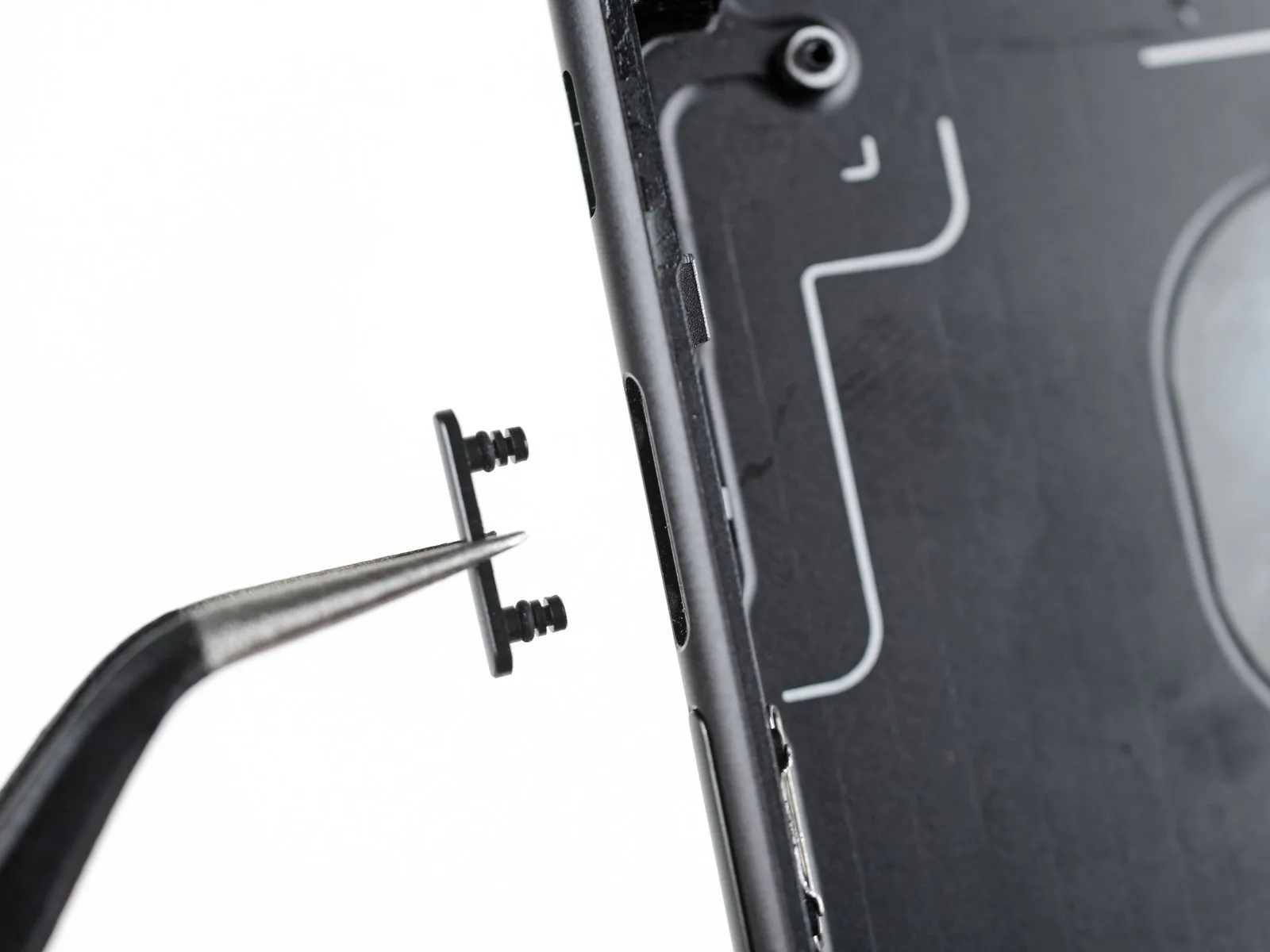
- Carefully detach the button, noting the presence of two small gaskets; Apple’s design prioritizes water resistance.
- Due to its more complex construction, separating this assembly into its three components presents a greater challenge compared to the button covers typically found in Apple products; however, the robust seal it creates should minimize the need for this disassembly.
Step 20
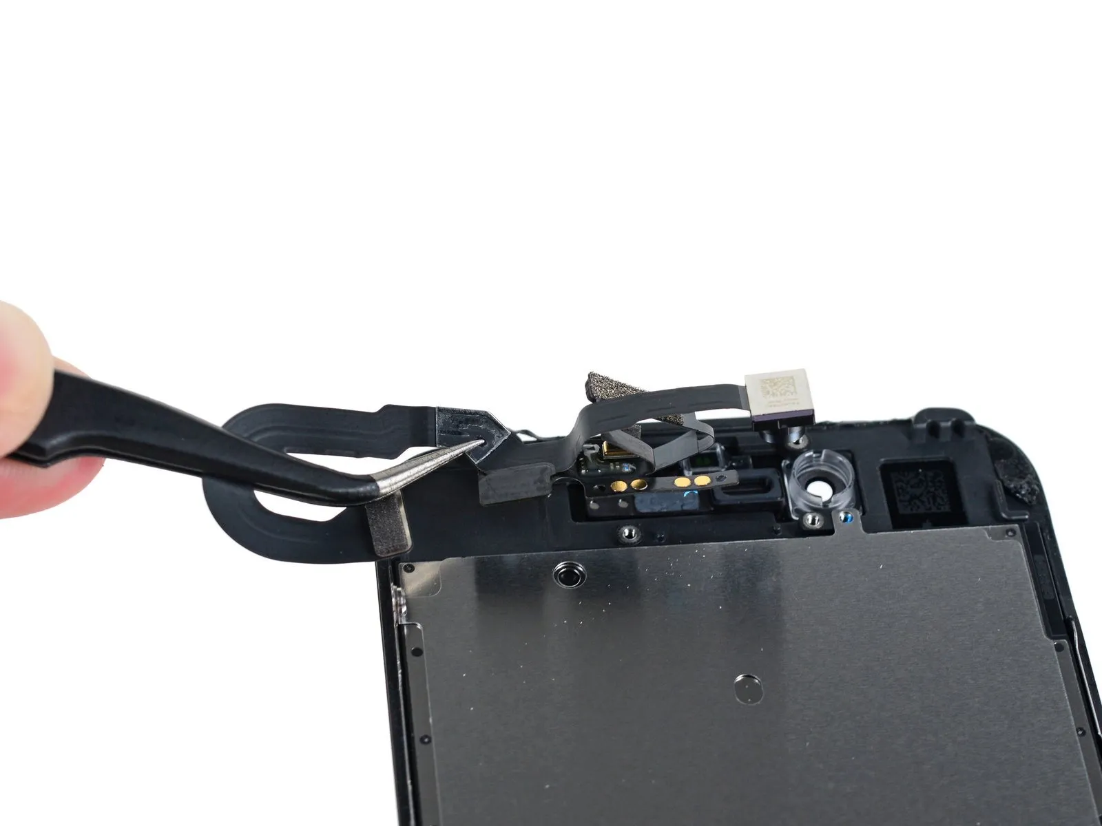
- Further examination of the display assembly requires assessment of the newly installed components.
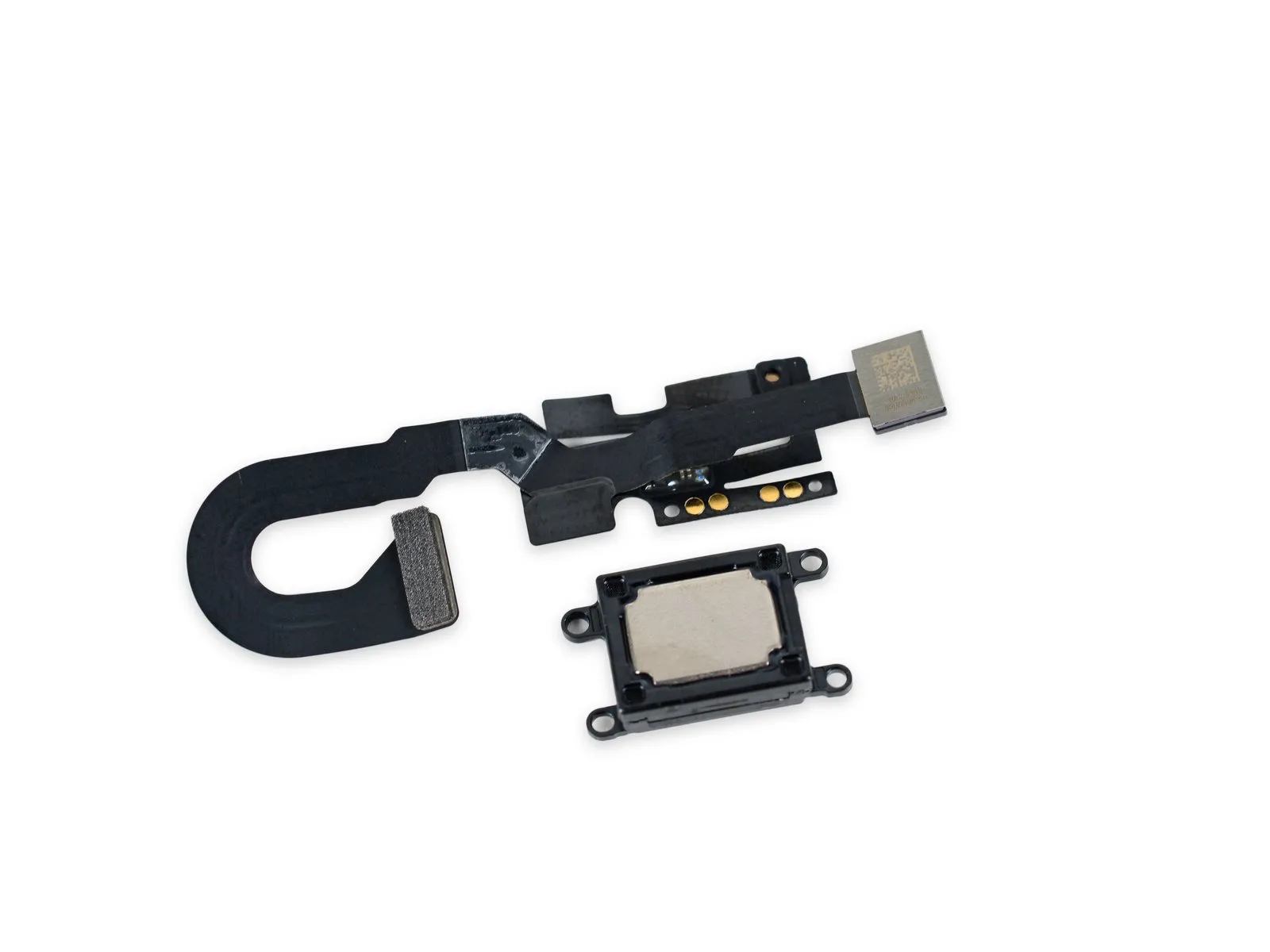
- Carefully separate the earpiece speaker from the chassis by gently removing the adhesive layer, ensuring all components remain undamaged.The front-facing camera features 7 megapixel resolution and FaceTime HD compatibility.The new camera incorporates deep trench isolation technology and auto image stabilization, representing a significant improvement over the 5MP FaceTime camera previously found in the 6s.
- The earpiece speaker now functions as a supplementary loudspeaker, enhancing the audio system to deliver authentic stereo sound.
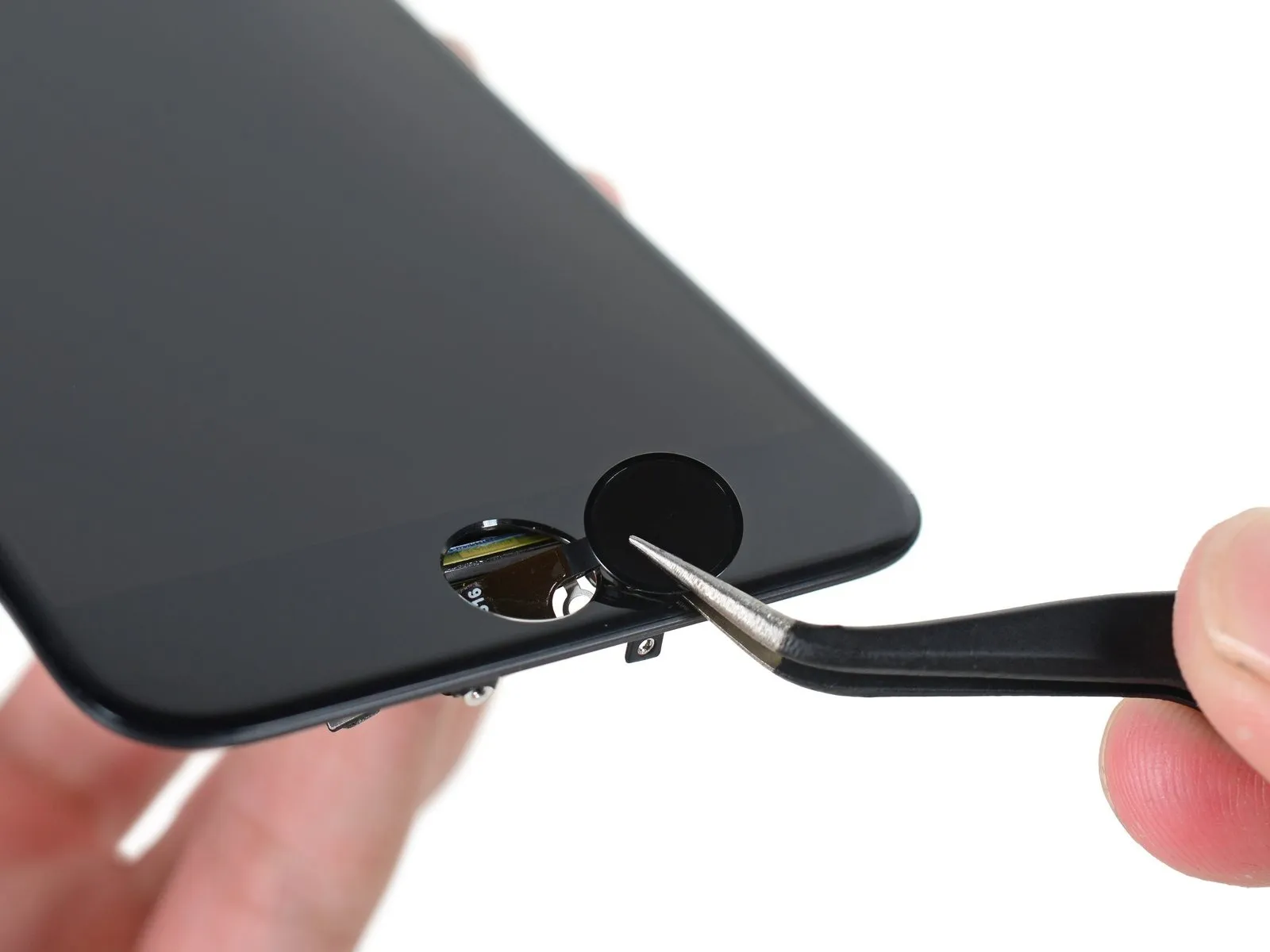
- Carefully remove the solid-state mini touch sensor, also known as the home button.
Step 21

- We appreciate your perseverance during this extensive disassembly process.
- Refer to the detailed disassembly guides for the iPhone 7 Plus and Apple Watch Series 2 for background information.
This instruction is a greeting and does not contain technical information suitable for rewriting within the constraints provided.