iPhone 7 Screen Replacement
This document details the procedure for substituting the display assembly on an iPhone 7.iPhone 7 screenThis repair instruction is specifically designed for use with comprehensive screen replacement kits. These kits incorporate the front assembly, earpiece speaker, and EMI shield, pre-attached to simplify the repair process.
- The essential step involves detaching the existing display and relocating the home button to the replacement screen to ensure Touch ID functionality.
Step 1 | Pentalobe Screws
- As a preliminary precaution, ensure your iPhone's battery has been depleted to a level below 25% prior to commencing the repair process.A fully charged lithium-ion batteryposes a risk of ignition and/or detonation if it sustains a puncture.
- Deactivate your iPhone by powering it down completely before you start taking it apart.
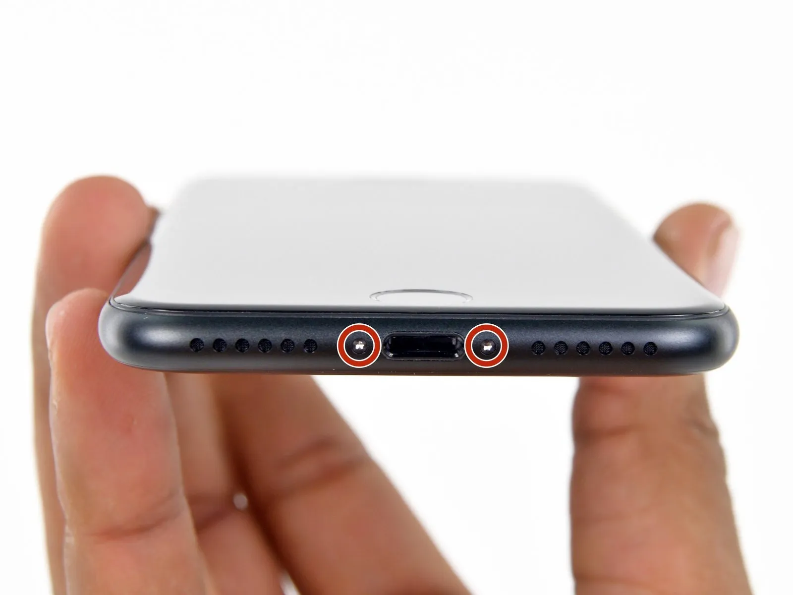
- Using a screwdriver, unscrew and remove the pair of 3.4 mm pentalobe screws located along the iPhone's lower edge.
- Separating the iPhone's display assembly will damage the integrated waterproof barriers; therefore, prepare replacement seals beforehand to prevent liquid ingress, or exercise extreme caution to avoid moisture exposure if you intend to reassemble the iPhone without new seals.
Step 2 | Mark your opening picks


- To avoid potential harm to your device, ensure the opening pick isn't inserted beyond its intended depth; this procedure will help you identify a safe insertion point by marking the pick.
- Determine the distance of3 mmfrom the pick's leading edge and use a permanent marker to create a visible indication on the opening pick.
- For enhanced reference, consider marking additional points on the pick's corners with varying measurements.
- As another option, affix a coin to the pick's shaft,3 mmaway from its tip.
Step 3 | Anti-Clamp instructions


The following three procedures showcase the Anti-Clamp, a specialized tool developed to simplify the opening process; should you choose not to utilize this tool, proceed past three steps to find an alternative approach.
Detailed instructions regarding the Anti-Clamp's operation can be found in a separate, dedicated guide.
- To release the Anti-Clamp's arms, move the blue handle in a rearward direction.
- Position the arms across either the left or right side of your iPhone.
- Place the suction cups close to the lower edge of the iPhone, situated directly above the home button—one on the device's front face, and one on its rear.
- Apply suction to the intended area by compressing the cups together.
- Should the iPhone's surface prove too slick for the Anti-Clamp to maintain a secure hold, applying adhesive tape can provide a more textured interface.
Step 4


- To secure the arm assemblies, advance the blue handle in its direction of travel.
- Rotate the handle in a clockwise direction,covering a full circle of 360 degrees,or continue rotation until the vacuum cups exhibit signs of deformation.
- Maintain proper alignment between the suction cups; should misalignment occur, slightly release the suction cups and reposition the arms.
Step 5


- Employ a heating device, such as aniOpenerto carefully guide it between the arms of theAnti-Clamp.
- Alternative heat sources, including hair dryers, heat guns, or hot plates, are acceptable; however, exercise caution as excessive temperatures may compromise the display or internal battery.
- Position theiOpenerin a folded position, resting it against the lower edge of the iPhone.
- Allow a sixty-second interval to permit the adhesive to soften and create a separation.
- Introduce an opening tool into the newly formed space.
- Should theAnti-Clamp fail to establish an adequate separation, increase the heat applied to the area and rotate the handle by ninety degrees.
- Avoid exceeding a ninety-degree rotation per increment, and observe a sixty-second pause between adjustments; allow theAnti-Clampand time to facilitate the separation process.
Step 6 | Heat the display
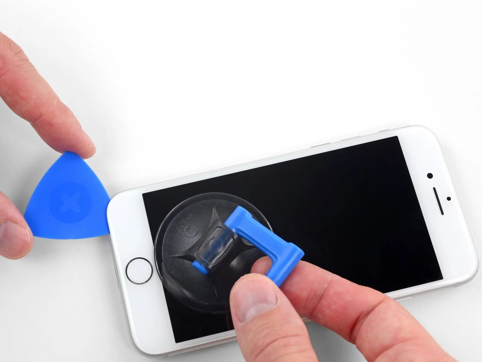
The subsequent three procedures detail the process of detaching the display assembly with the aid of a suction cup.
Applying heat to the bottom edge of the iPhone assists in reducing the viscosity of the adhesive that holds the display in place, thereby simplifying the separation process.
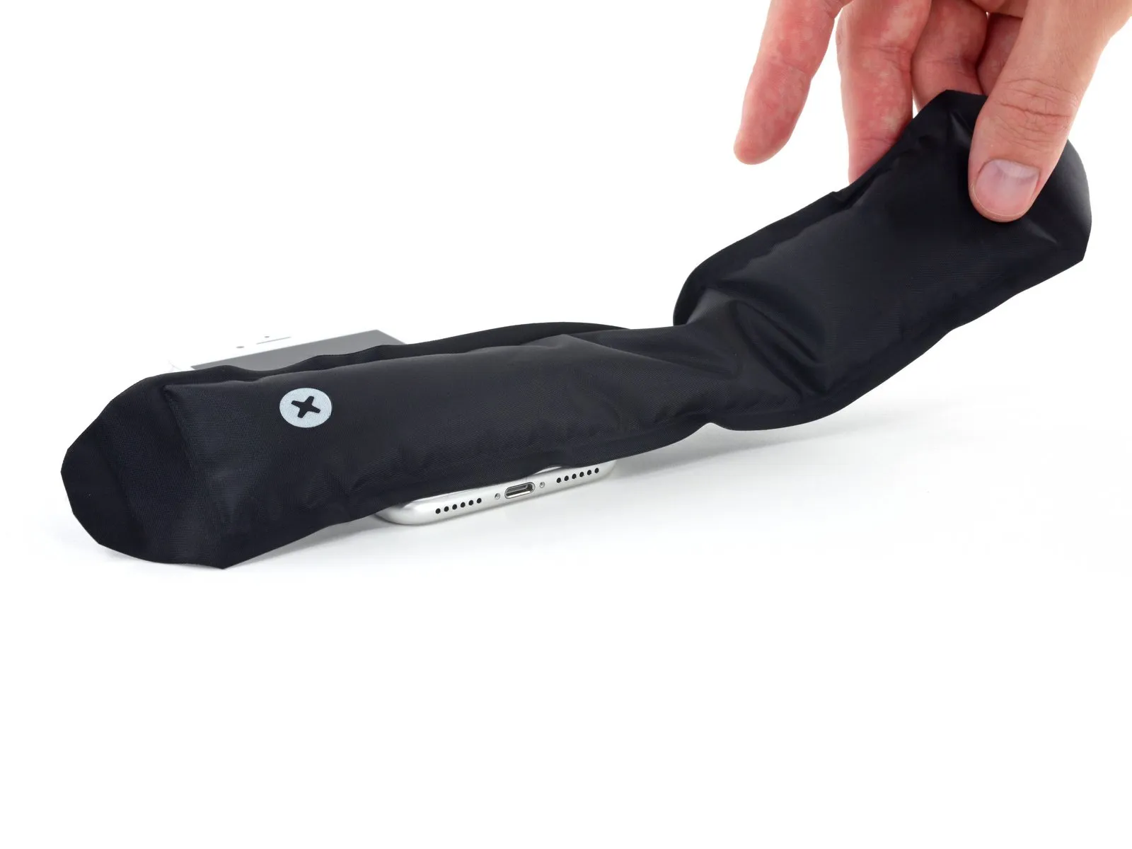
Employ a hairdryer, or alternatively prepare aniOpenerand apply it to the lower edge of the device for approximately 90 seconds to reduce the adhesive's bonding strength.
Step 7 | Separate the display
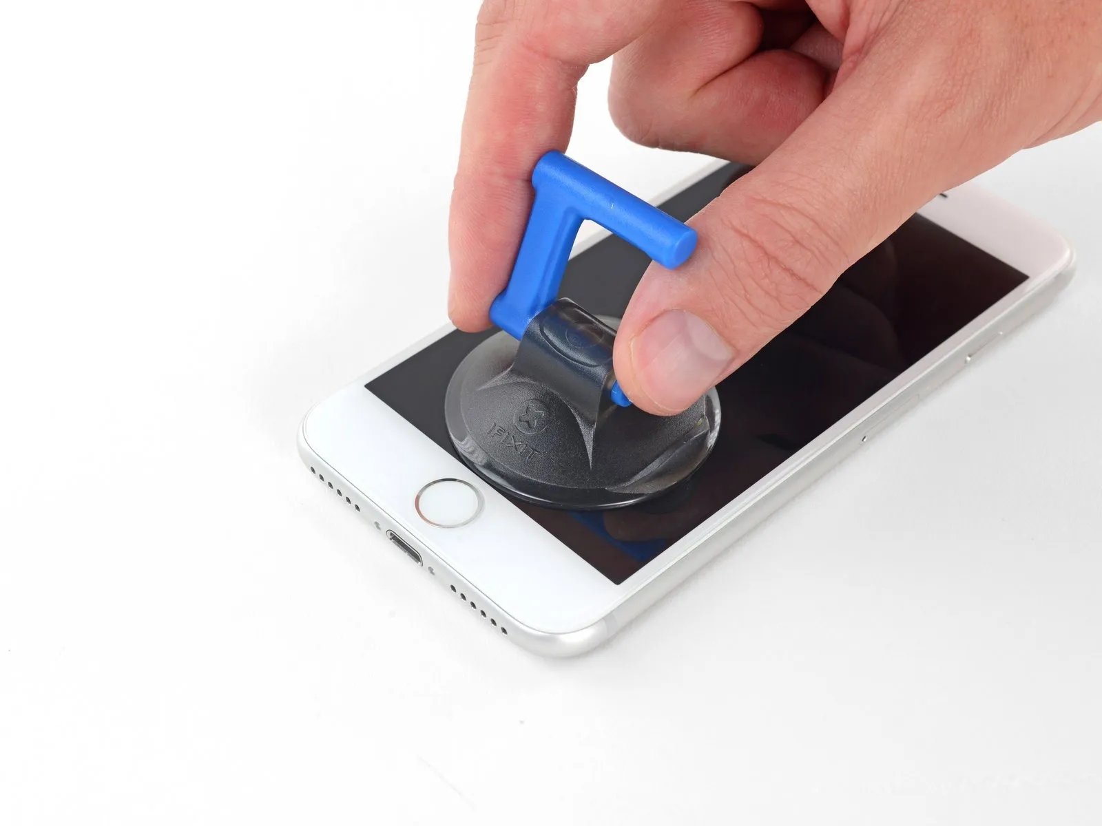

Securely affix a suction cup to the bottom portion of the front panel, positioning it directly over the home button area.
Ensure the suction cup's surface remains clear of the home button's location to guarantee a complete and airtight bond between the cup and the glass.
Step 8
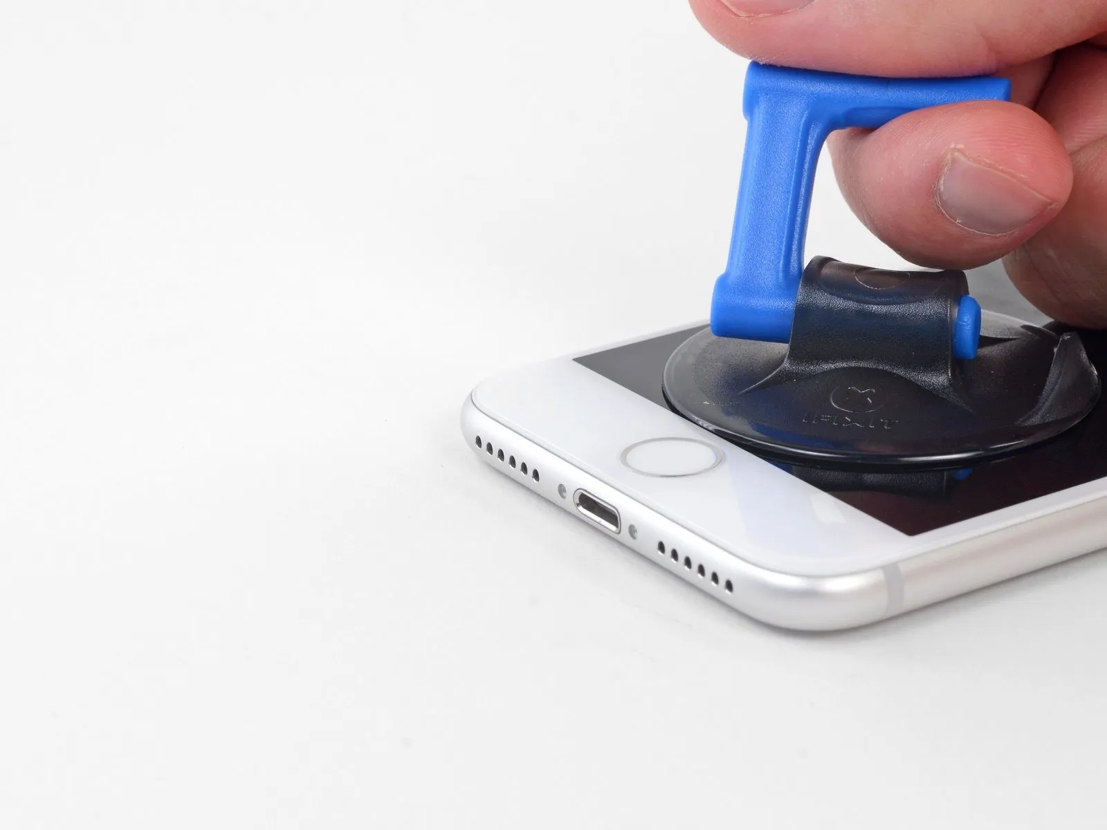


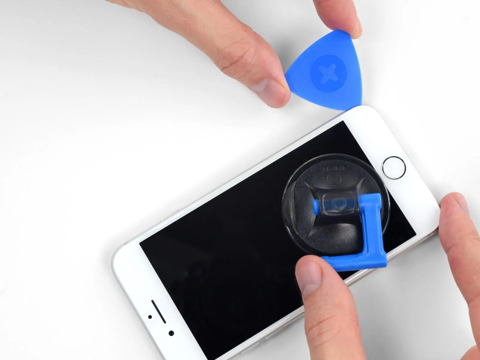
Apply steady, consistent upward force to the suction cup to generate a small separation between the display assembly and the device's border.
Carefully slide an opening tool into the newly formed space.
Due to the robust, waterproof sealant securing the display, establishing this initial separation requires considerable effort; should you encounter difficulty, applying additional heat and gently oscillating the display upward and downward will help to reduce the adhesive's strength, allowing for sufficient separation to accommodate your tool.
Step 9


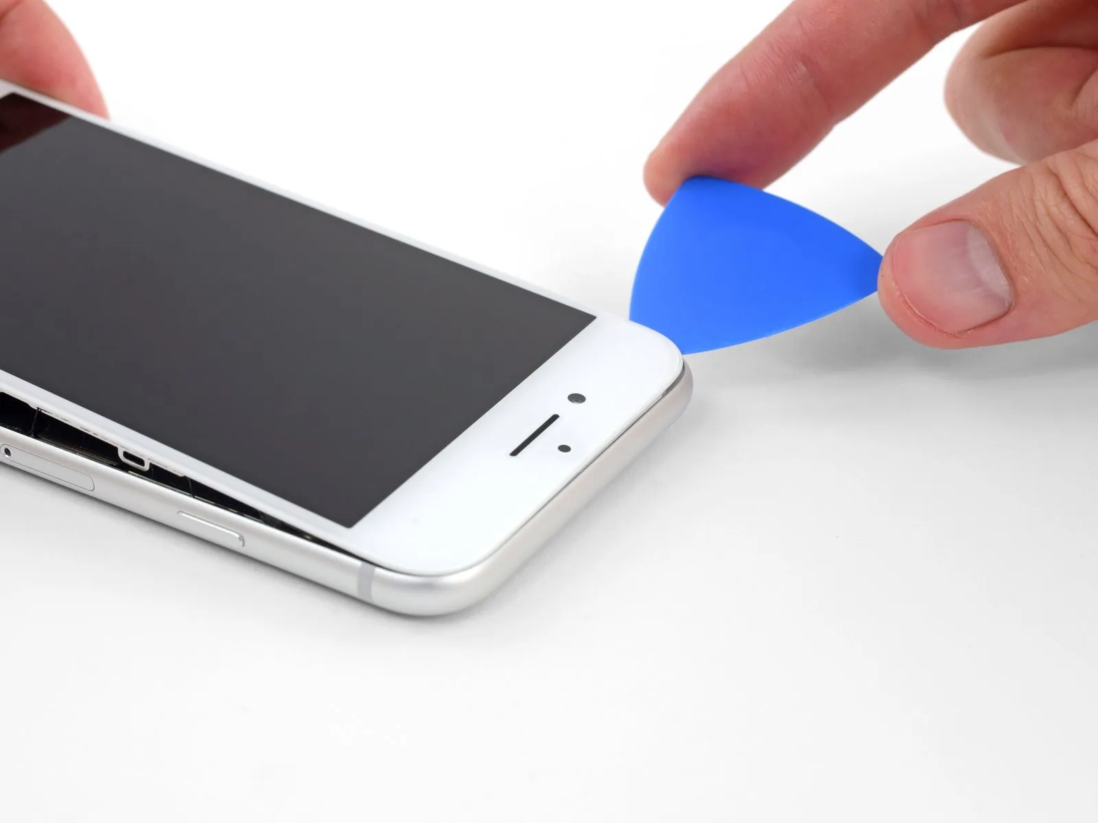
- Begin separating the display assembly from the device's frame by inserting a prying tool beneath the left edge, initiating the separation at the bottom and progressing upwards towards the volume buttons and the silent switch, effectively disrupting the adhesive bond.
- Cease the separation process in close proximity to the upper-left corner of the display panel.
- Refrain from attempting to dislodge the display's upper edge from the rear casing, because it is secured using fragile plastic retaining clips that are susceptible to damage.
Step 10 | Screen information

Along the right side of your iPhone, you'll find sensitive wiring. Avoid inserting any tools in this area to prevent potential cable damage.
Step 11


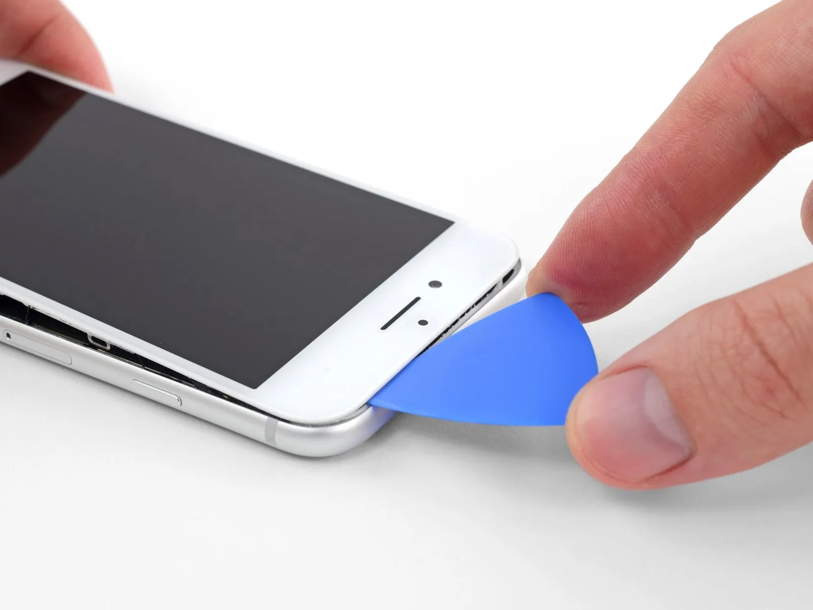
- To release the adhesive, carefully re-position your tool at the lower-right edge of the iPhone, then maneuver it along the corner and up the right side, sliding to detach the adhesive.
- Ensure your opening tool does not penetrate beyond 3 millimeters, to prevent potential harm to the delicate display cable connections.
Step 12


- Carefully elevate the display's lower border by applying upward force to the suction cup.
- Avoid lifting the display beyond an angle of 15 degreesas exceeding this limit could potentially damage or sever the flexible ribbon cables that provide the display's electrical connections.
- Detach the suction cup from the front panel by grasping and pulling on the small protrusion located on its surface.
Step 13

Step 14


Step 15


Prevent the display from moving by securing it in an upright position using a support during the repair process.Avoid forcing separation, as multiple sensitive ribbon cables are still attached to the logic board.
To maintain accessibility, prop the display at an angle using a stabilizing object while performing subsequent repair steps.
Step 16 | Battery Disconnection
- Three1.2 millimetersin length
- One2.4 millimetersin length
Step 17
Step 18
- Employ the tip of a spudgerto disengage the battery connector from its corresponding receptacle on the logic board.
- Gently elevate the connector cable a small amount to ensure it remains disconnected from the socket, thus preventing any electrical power from reaching the device.
Step 19 | Display Assembly
Prior to any cable manipulation in this procedure, ensure the battery is completely disconnected.This precaution is essential before detaching or reattaching the cables detailed in this step.
- Employ a spudgeror a fingernail to release the two lower display connectors; achieve this by applying upward pressure directly above them to separate them from their corresponding sockets on the logic board.
- To establish a secure connection for these cables, apply pressure to one end until an audible click confirms its placement, and then repeat this process for the opposite end. Avoid applying pressure to the central portion of the connector; even minor misalignment can result in bending, potentially leading to irreversible damage.
Should you observe a blank display, the appearance of white lines, or a diminished or absent touch response following reassembly, attempt to carefully detach and reconnect both cables, verifying their complete and proper seating.
Step 20
- Detach the pair of 1.3-millimeter Phillips #000 screwswhich hold the bracket positioned above the front panel sensor assembly's connector.
- Certain devices may be designated as Y000; Apple introduced this identifier for some models during a portion of their production run.
Step 21
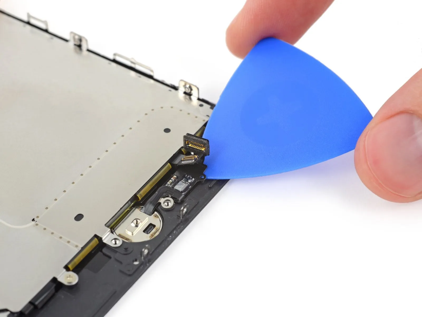
- To proceed, detach the connector linking the front panel sensor assembly to its corresponding socket located on the logic board.
- For optimal results and to prevent damage, reattach this press-fit connector by engaging one end at a time.
Step 22
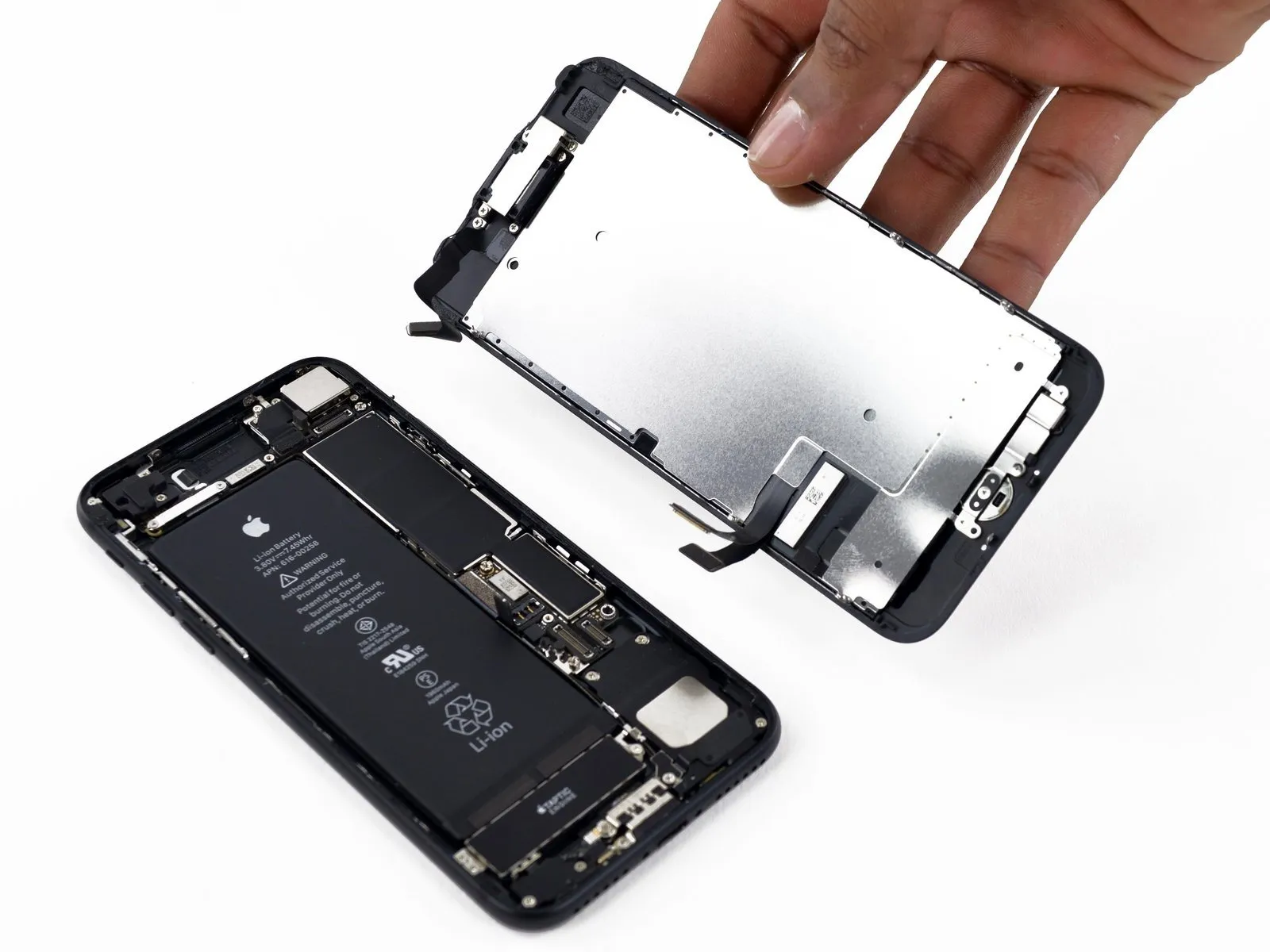
- Detach the display assembly from the device.
- If you intend to substitute the adhesive securing the display's perimeter during reassembly, halt the process at this juncture.
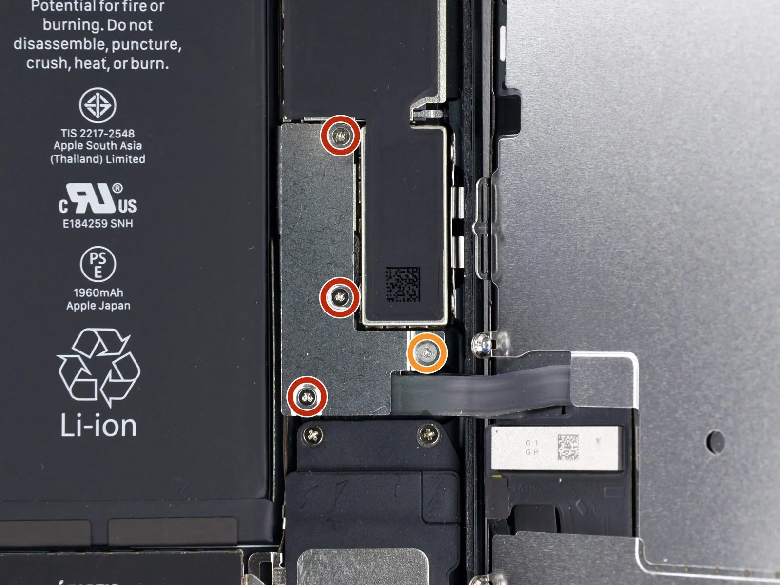
Step 23 | Home/Touch ID Sensor

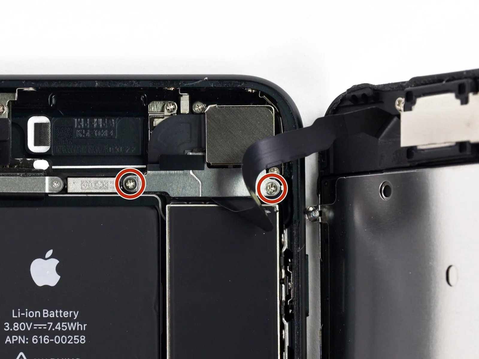
- To detach the bracket covering the home/Touch ID sensor, first extract the four Y000 screws that hold it in place.
- A single 1.1-millimeter screw is required.
- Three screws, each measuring 1.3 millimeters, are also needed.
- When putting the device back together, exercise caution and avoid excessive tightening of these screws, as this could impair the functionality of the home button.
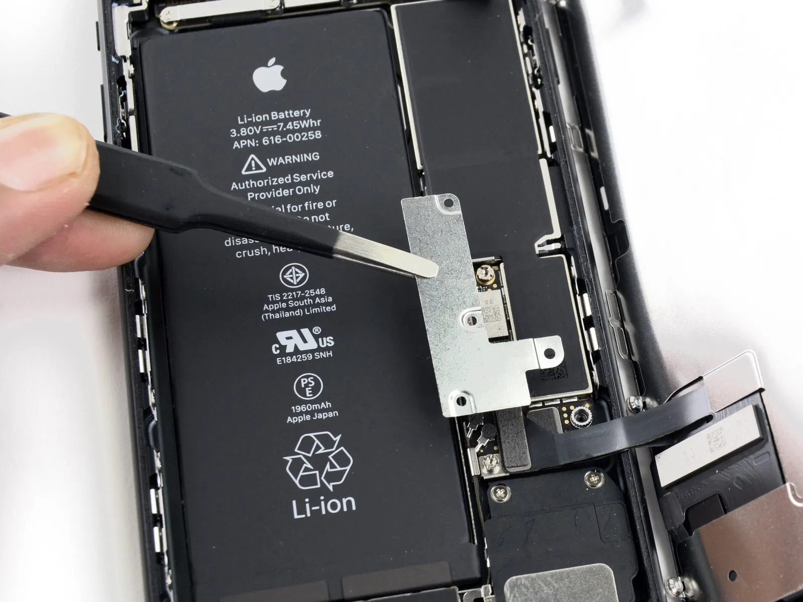
Step 24

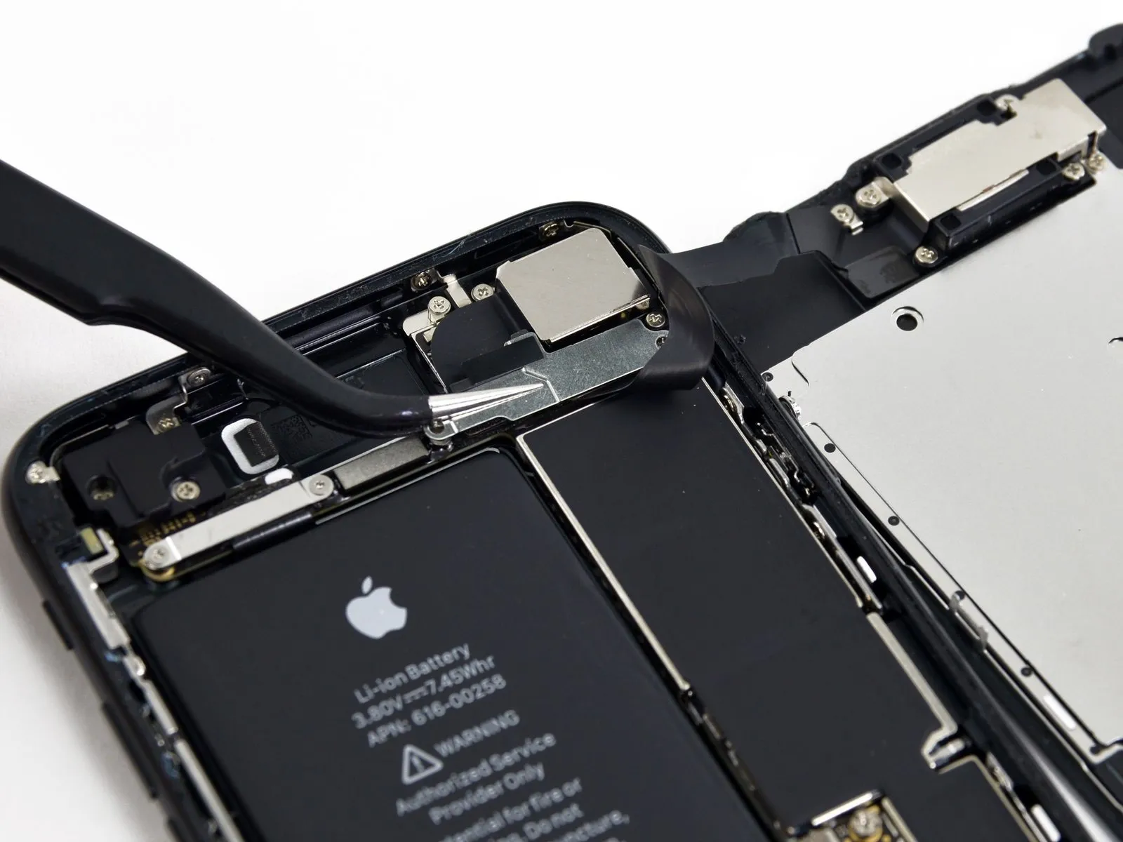
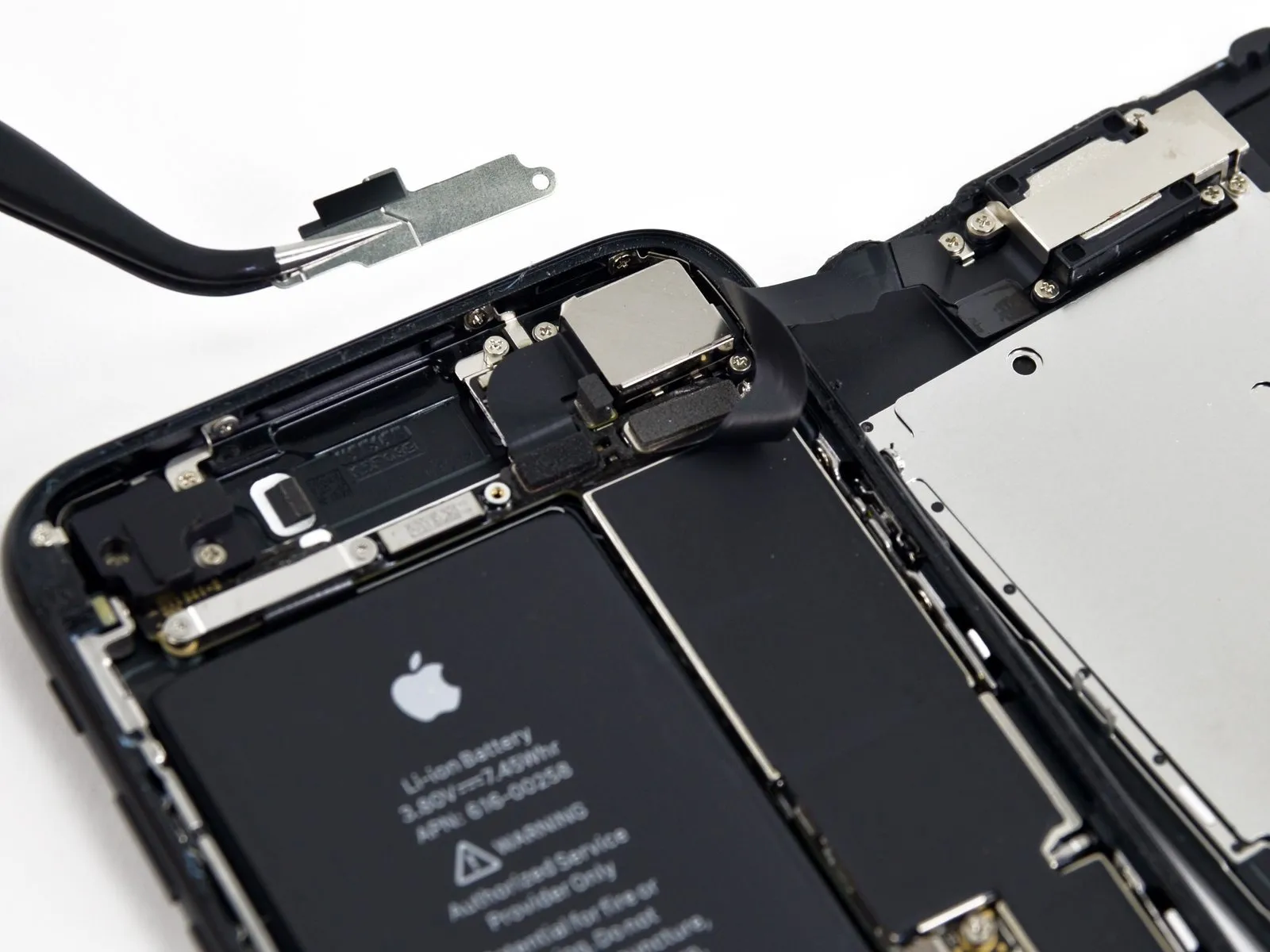
- Detach the retaining clip that fastens the home button and Touch ID sensor assembly in place.
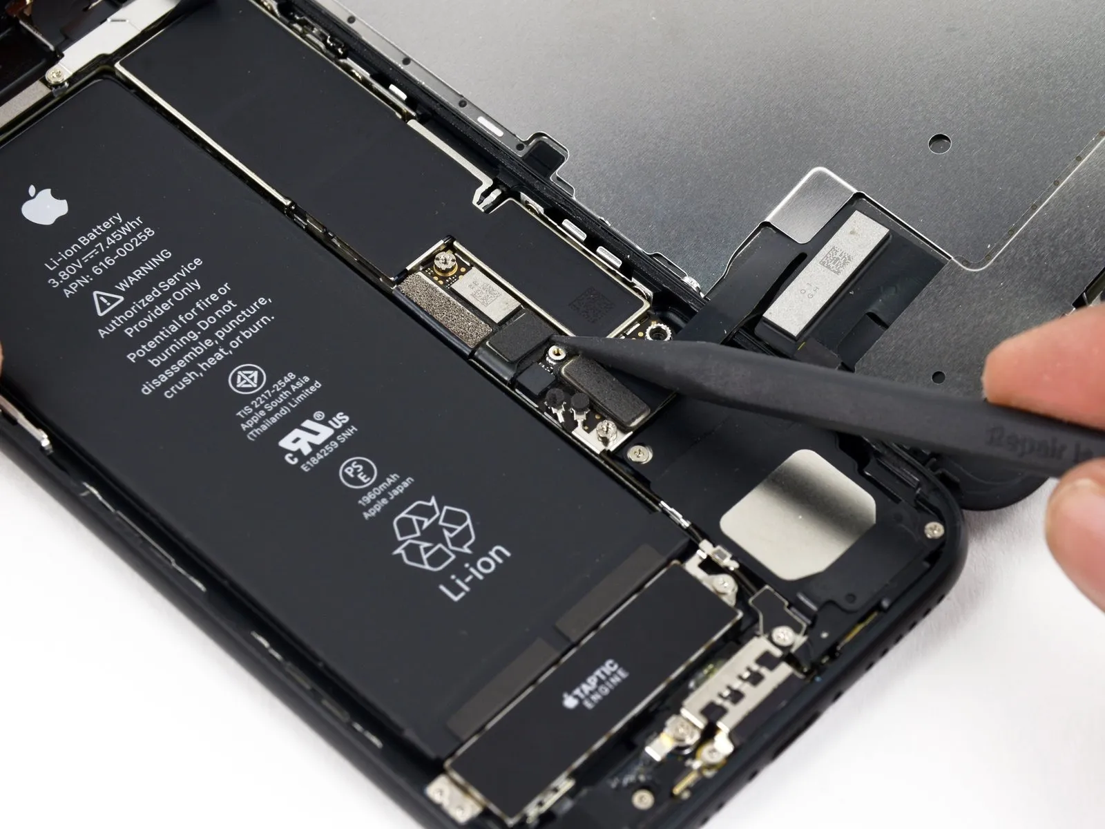
Step 25


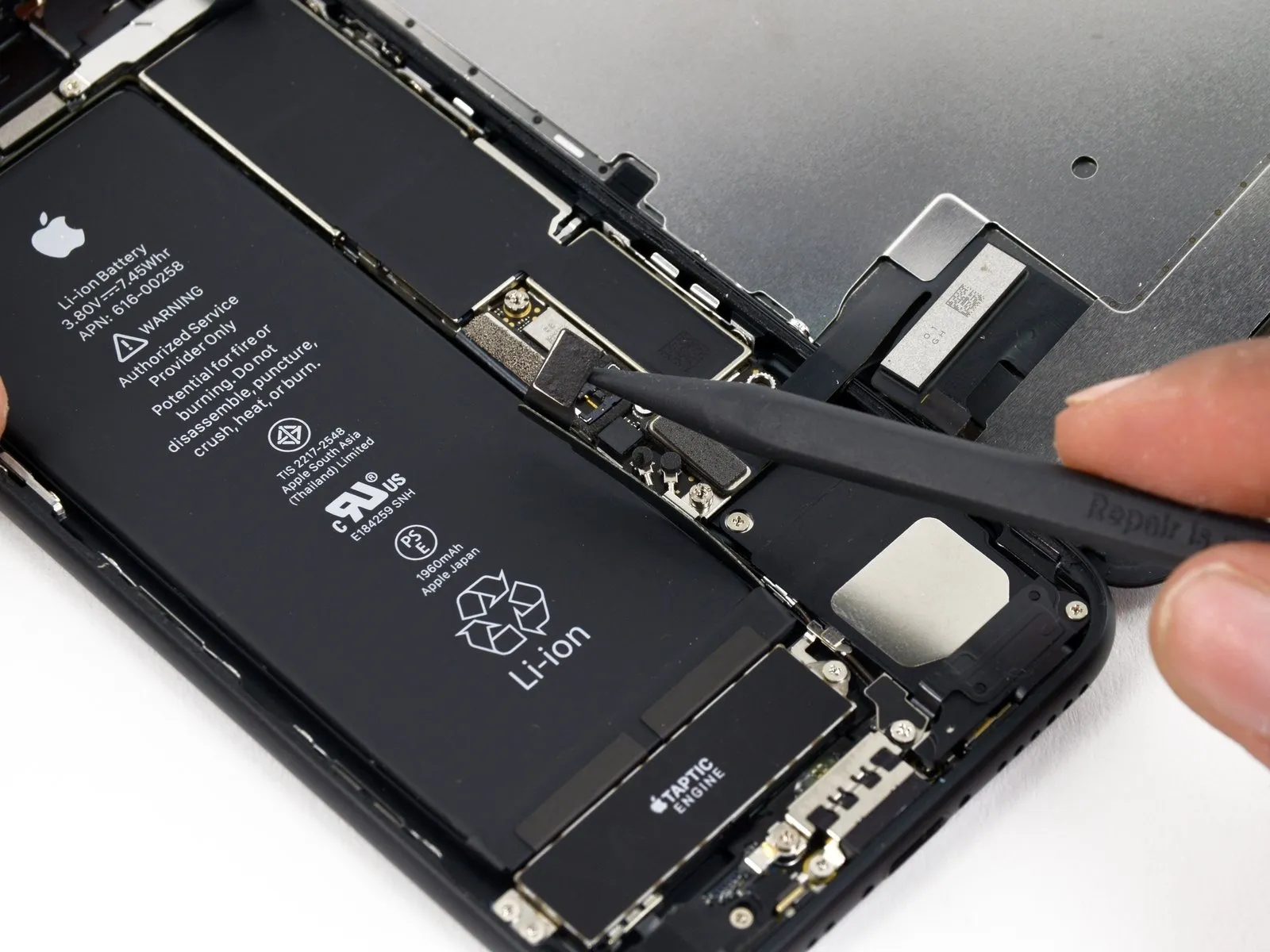
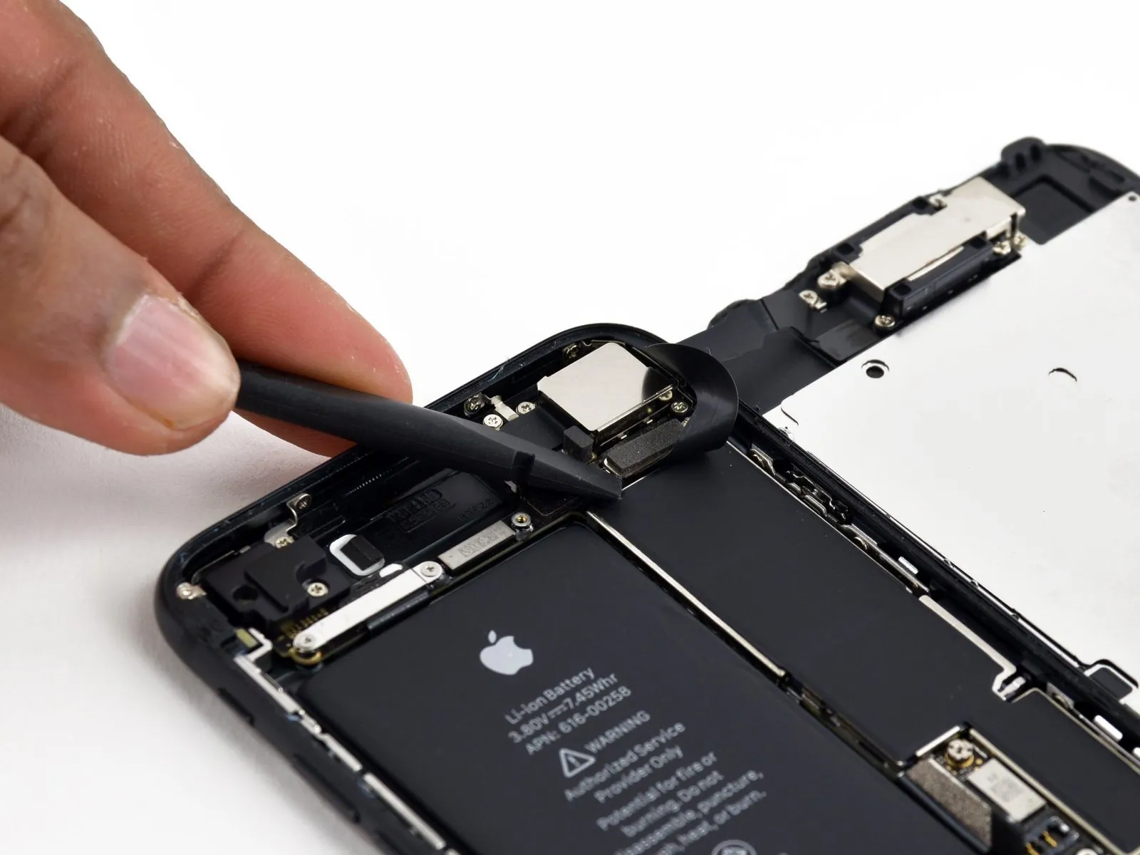
- Carefully lever the underside of the left side of the home button cable connector to release it from its mating socket.
- Should the entire connector assembly lift unexpectedly without detaching, apply downward pressure to the cable's upper edge, utilizing the broad surface of yourspudger, and concurrently lift the left edge of the connector. Exercise extreme caution to prevent any harm to the cable or connector, as doing so will render the sensor inoperable.
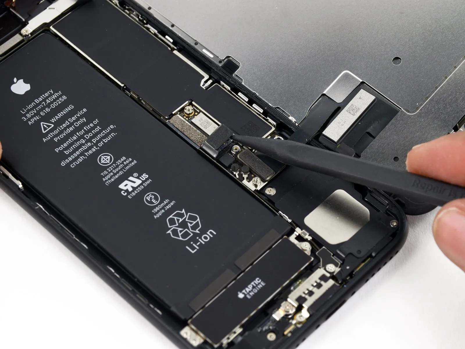
Step 26


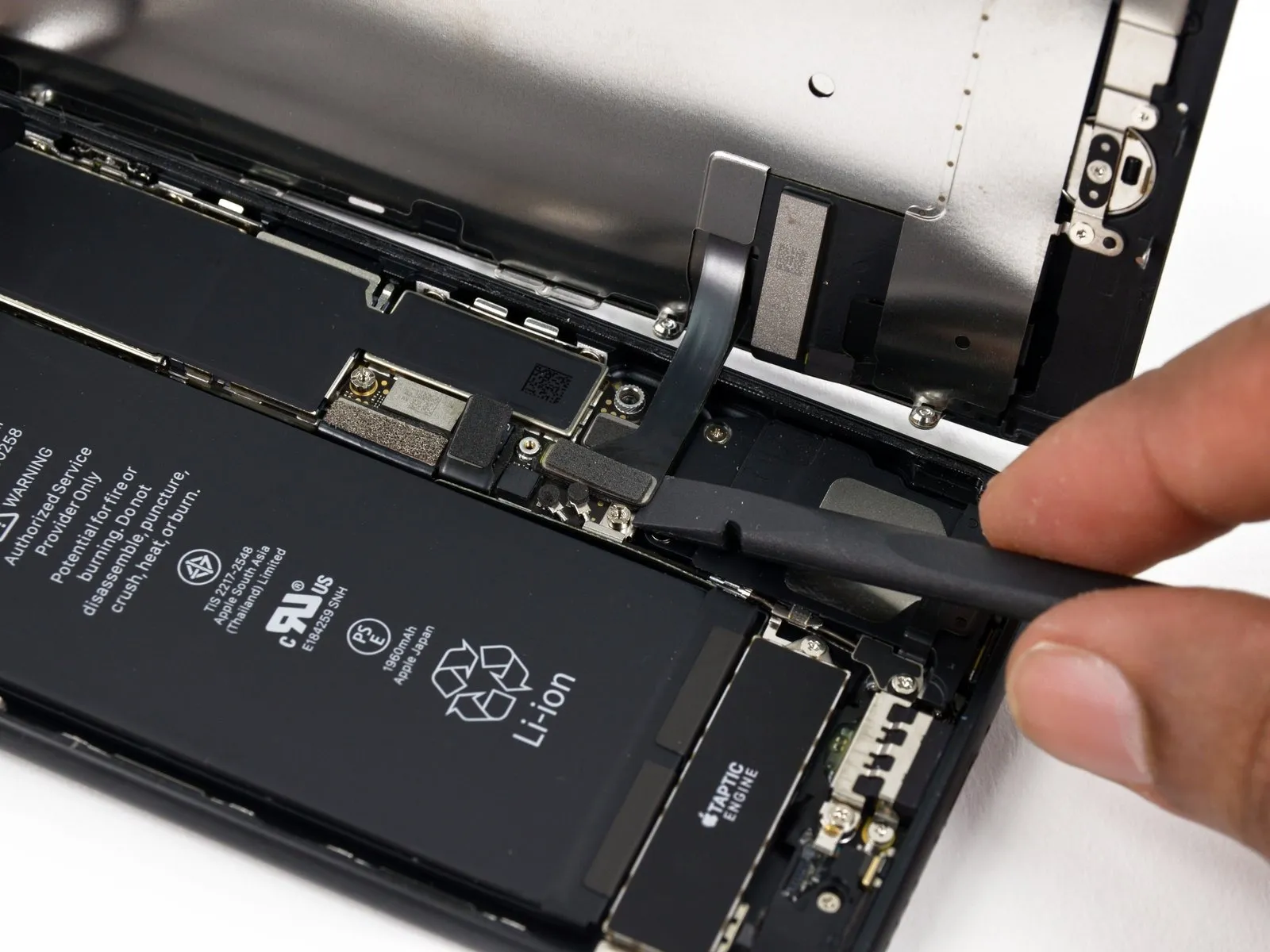
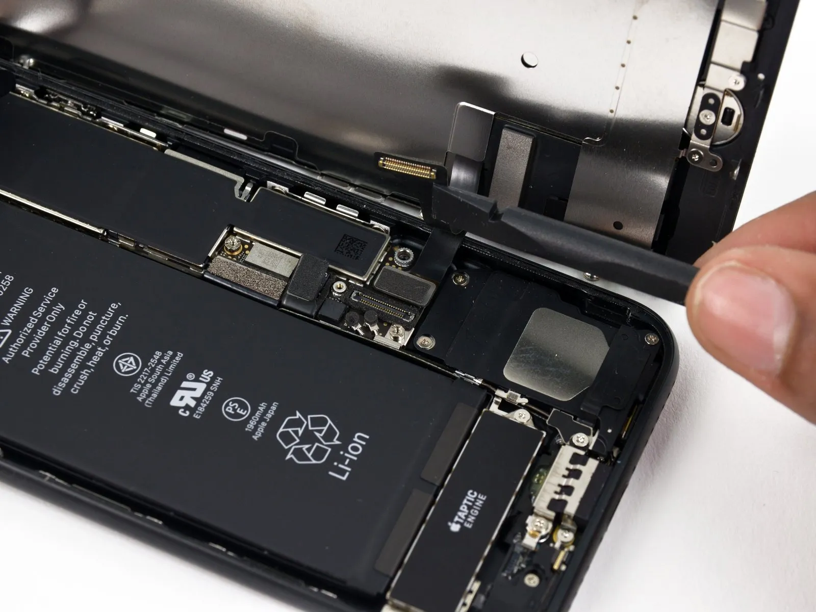
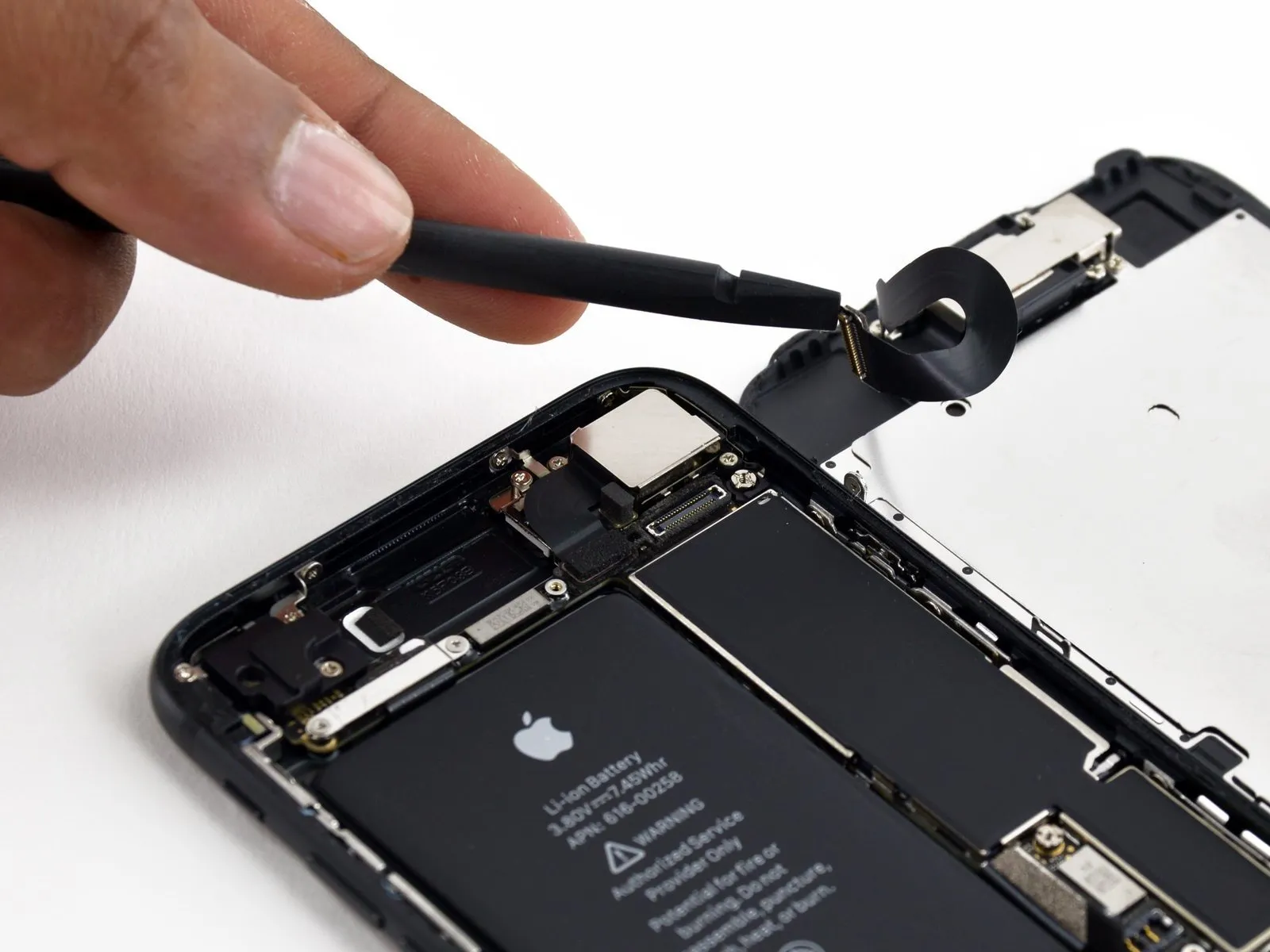
- Gently lift the connector situated beneath the components, and reposition it to allow access to the home/Touch ID cable.
- Damage to your iPhone is highly probable if this procedure isn't performed with caution; proceed deliberately and exercise precision when using your tool. Any harm inflicted upon the Touch ID hardware necessitates replacement exclusively by Apple.
- Should the connector resist lifting, apply heat using a hair dryer or iOpener to loosen the adhesive holding it in place, and then attempt to lift it again.
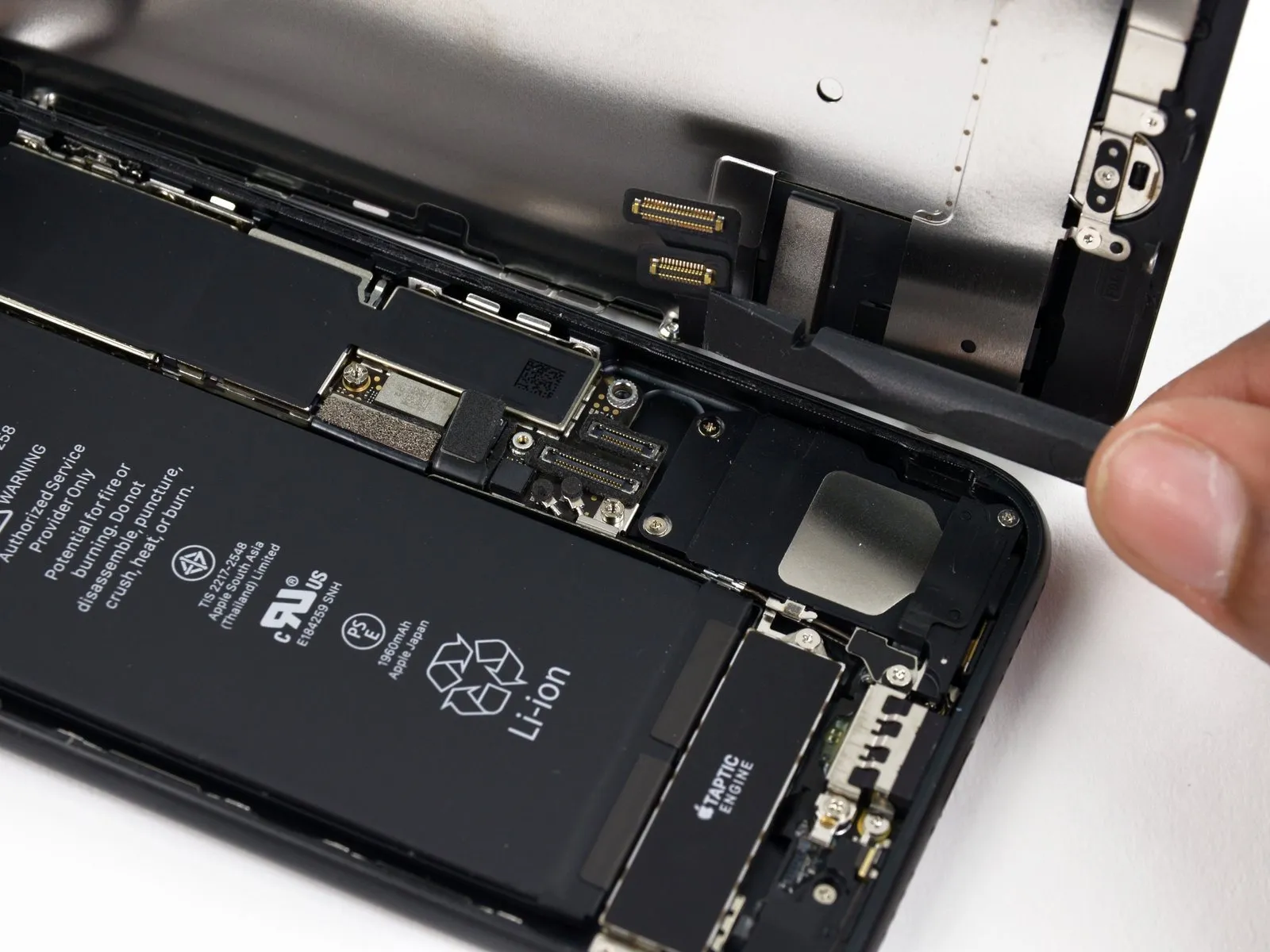
- Avoid a full separation of the connector; instead, elevate it slightly to facilitate removal of the underlying home/Touch ID sensor cable.
Step 27

Applying warmth to the region surrounding the home button and Touch ID sensor can assist in loosening the adhesive securing its fragile cable, which will simplify the removal process and prevent damage.
Turn the display assembly so the reverse side faces up; then, utilize a hairdryer or an iOpener, directing heat to the display's lower edge for approximately 90 seconds to reduce the adhesive's tackiness.
Step 28


Carefully disengage the adhesive securing the home/Touch ID sensor cable to the rear surface of the display assembly, utilizing a specialized opening tool.
Step 29

- Detach thehome/Touch ID sensor assemblyby raising it from the front surface of the display panel.
- During reassembly, initially route the cable through the opening located on the front of the display.
- The newly acquired component might include an additional Y000 screw positioned to the right of the Home Button; discard this superfluous screw to facilitate proper reinstallation of the home button bracket.
- Utilize this instructional document to affixreplacement display adhesiveto your screen.