iPhone 6s Plus Wi-Fi/Bluetooth Antenna Replacement
Using the instructions provided, substitute the damaged component with a new one.The internal antenna, responsible for wireless network and Bluetooth connectivity,Using a 5/32-inch hex key, carefully tighten the retaining screw to a torque of 6 in-lbs, ensuring the spindle bearing is properly seated and avoiding over-tightening which could damage the bearing.Apple's 6s Plus model..
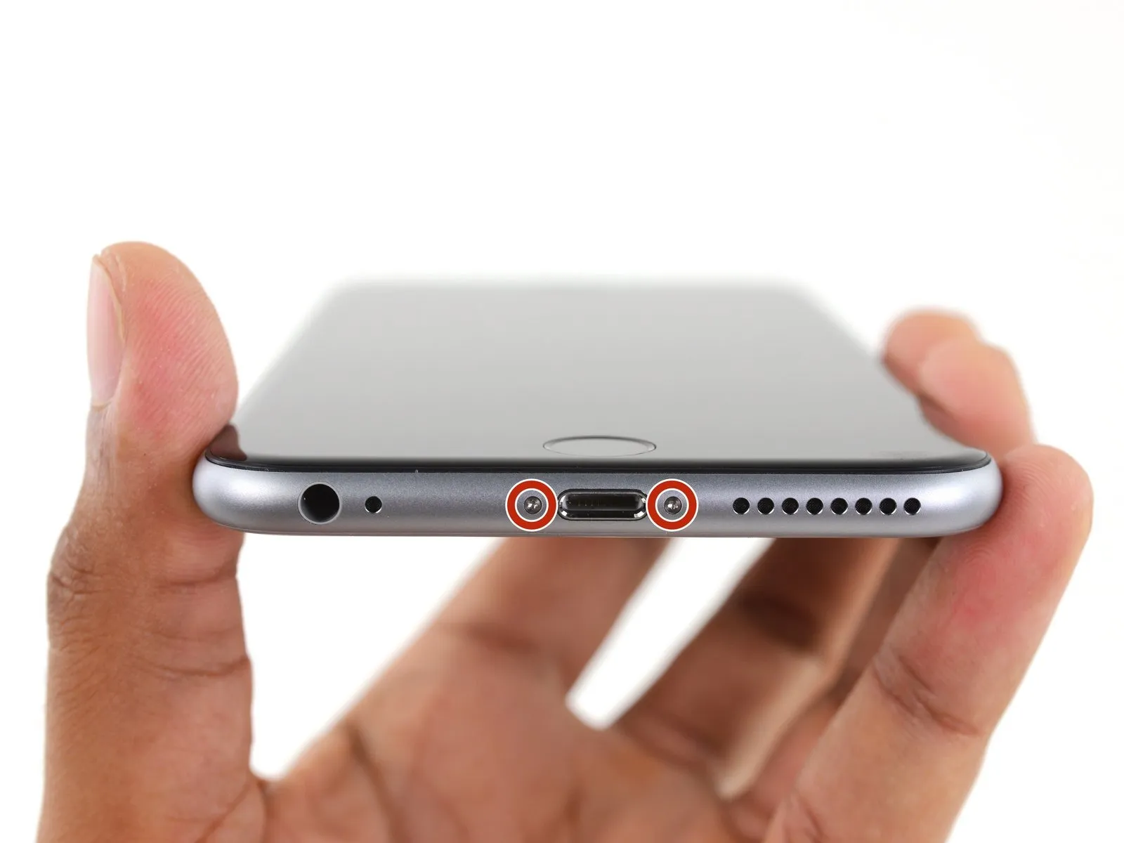
Step 1 | Pentalobe Screws
- To prevent potential hazards and damage, ensure the battery's charge level is reduced to less than 25% prior to beginning the disassembly process.Ensure the battery is fully charged.A puncture can result in combustion and/or a forceful rupture.
- To prevent electrical shock or damage, ensure the iPhone is completely de-energized prior to starting the repair process.
- Using a Pentalobe screwdriver, detach the two screws, each measuring 3.4 mm, located on both sides of the Lightning port.
Step 2 | Anti-Clamp instructions


- To simplify the subsequent opening process, the following instructions utilize the Anti-Clamp tool, a custom-designed aid; if you do not have this tool, proceed to the instructions three steps further down.
- Refer to the included guide for detailed procedures regarding the Anti-Clamp's operation.
- To release the Anti-Clamp's arms, move the blue handle in a rearward direction.
- Position the arms so they extend across either the left or right side of the iPhone.
- Affix two suction cups, one to the front and one to the rear of the iPhone, placing them close to the lower edge, directly above the home button.
- Apply vacuum by pressing the cups firmly against the surface you intend to work on.
- To improve the Anti-Clamp's grip if the iPhone's exterior feels excessively smooth, apply adhesive tape to the device's surface.
Step 3


- To secure the arms, advance the blue handle in its direction.
- Rotate the handle fully, completing a 360-degree turn, observing for the initial expansion of the cups.
- Maintain parallel positioning of the suction cups; should misalignment occur, gently release the suction cups' grip and reposition the arms.
- Once sufficient space is created by the Anti-Clamp, slide a prying tool beneath the display.
- To ensure adequate separation, reposition the handle by 90 degrees.
- Allow the Anti-Clamp device to function and permit several seconds of inactivity following each incremental adjustment, limiting each rotation to a maximum of 90 degrees.
Step 4 | Opening Procedure
- Lacking an Anti-Clamp tool, proceed with the subsequent three steps to utilize a suction handle.
- Using either an iOpener or a hair dryer, gently warm the bottom edge of the iPhone's casing with moderate heat for approximately 60 seconds.
- Applying heat will loosen the adhesive bonds holding the display in place, facilitating separation.
Step 5
- Removing the 6s Plus display releases a perimeter adhesive strip; replacement adhesive strips should be prepared beforehand if desired. Functionality remains unaffected whether the adhesive is replaced or not.
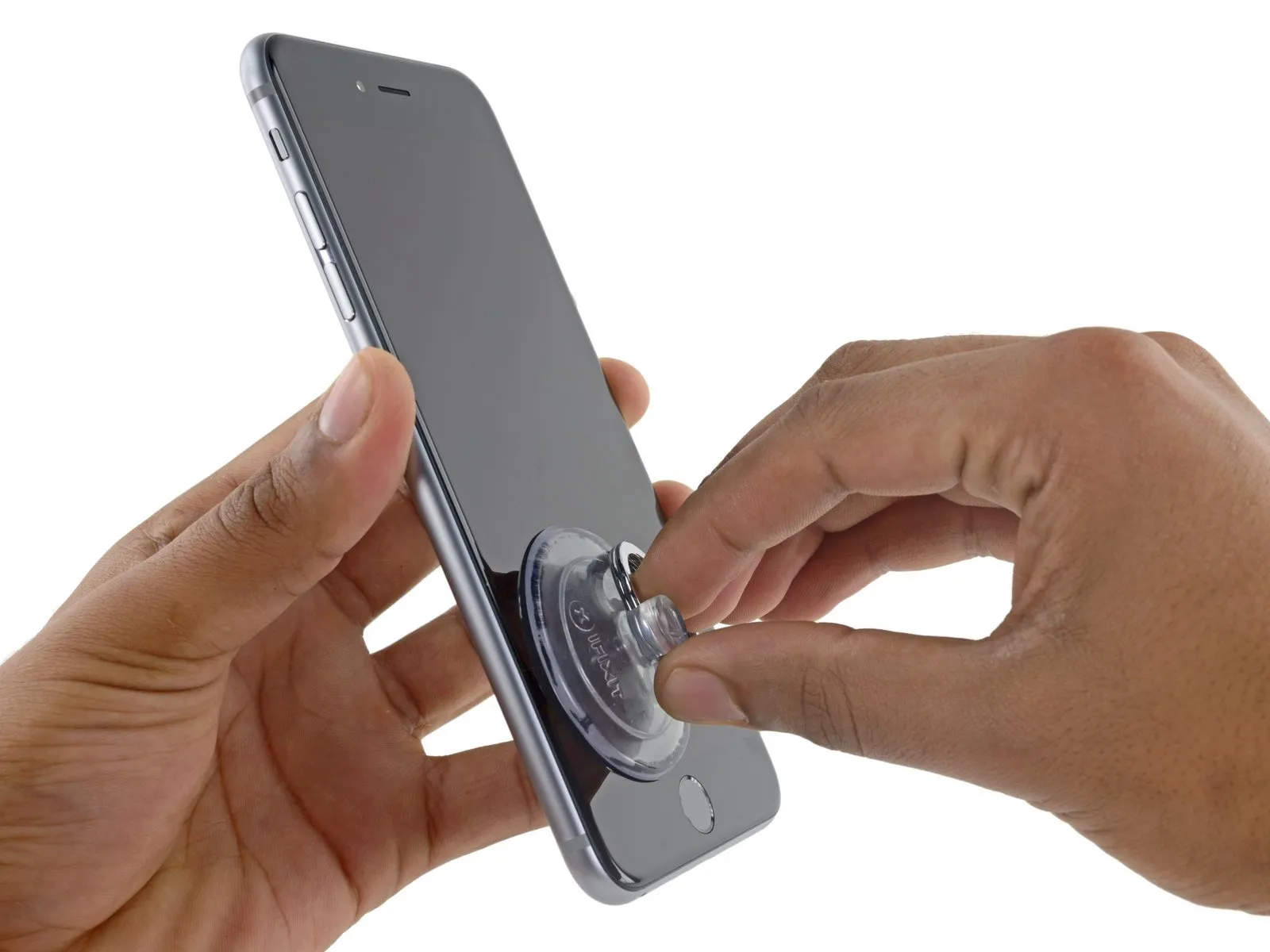
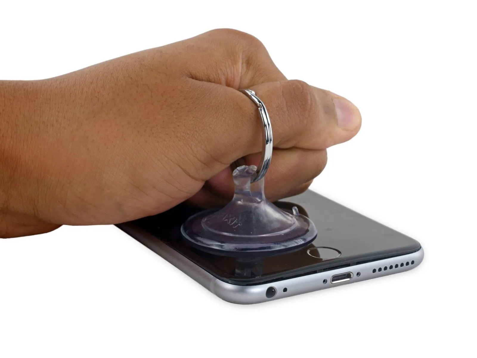
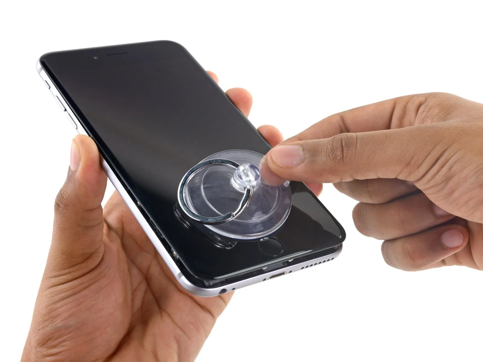
- Using a suction cup, secure the lower left portion of the display assembly.
- To facilitate suction cup attachment when a display exhibits severe cracking, apply a sheet of clear packing tape across the damaged area; as an alternative, a robust adhesive tape can be substituted for the suction cup. Should neither of these methods prove effective, secure the suction cup directly to the fractured screen using superglue.
Step 6
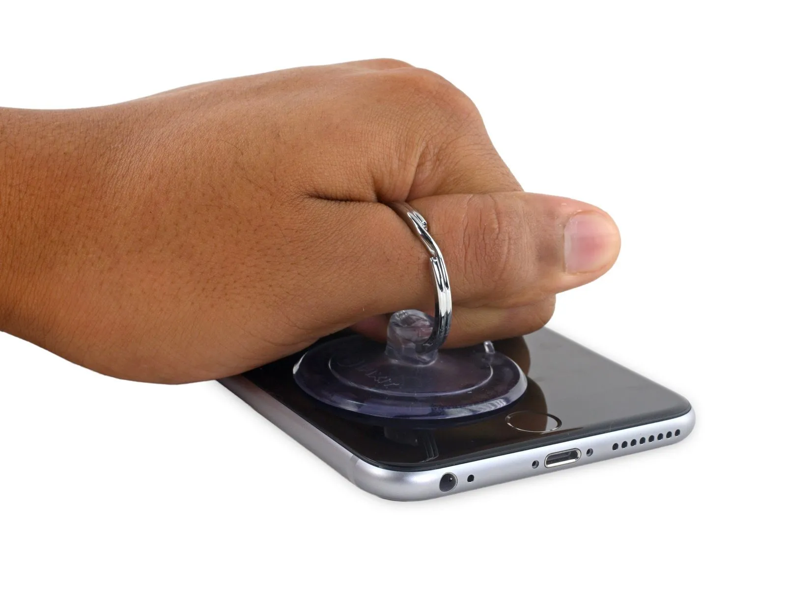
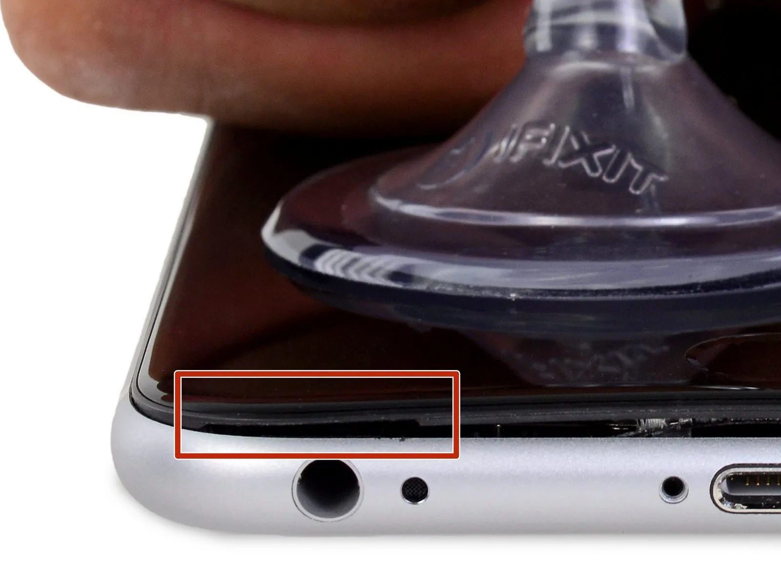
- Apply steady, even force to lift the suction cup, generating a small separation between the front panel and the rear case.
- To avoid display assembly damage, use only the minimum force necessary to separate the display assembly from the rear case, creating a slight opening.
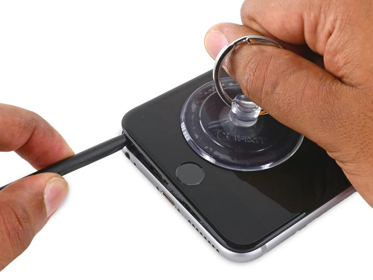
Step 7

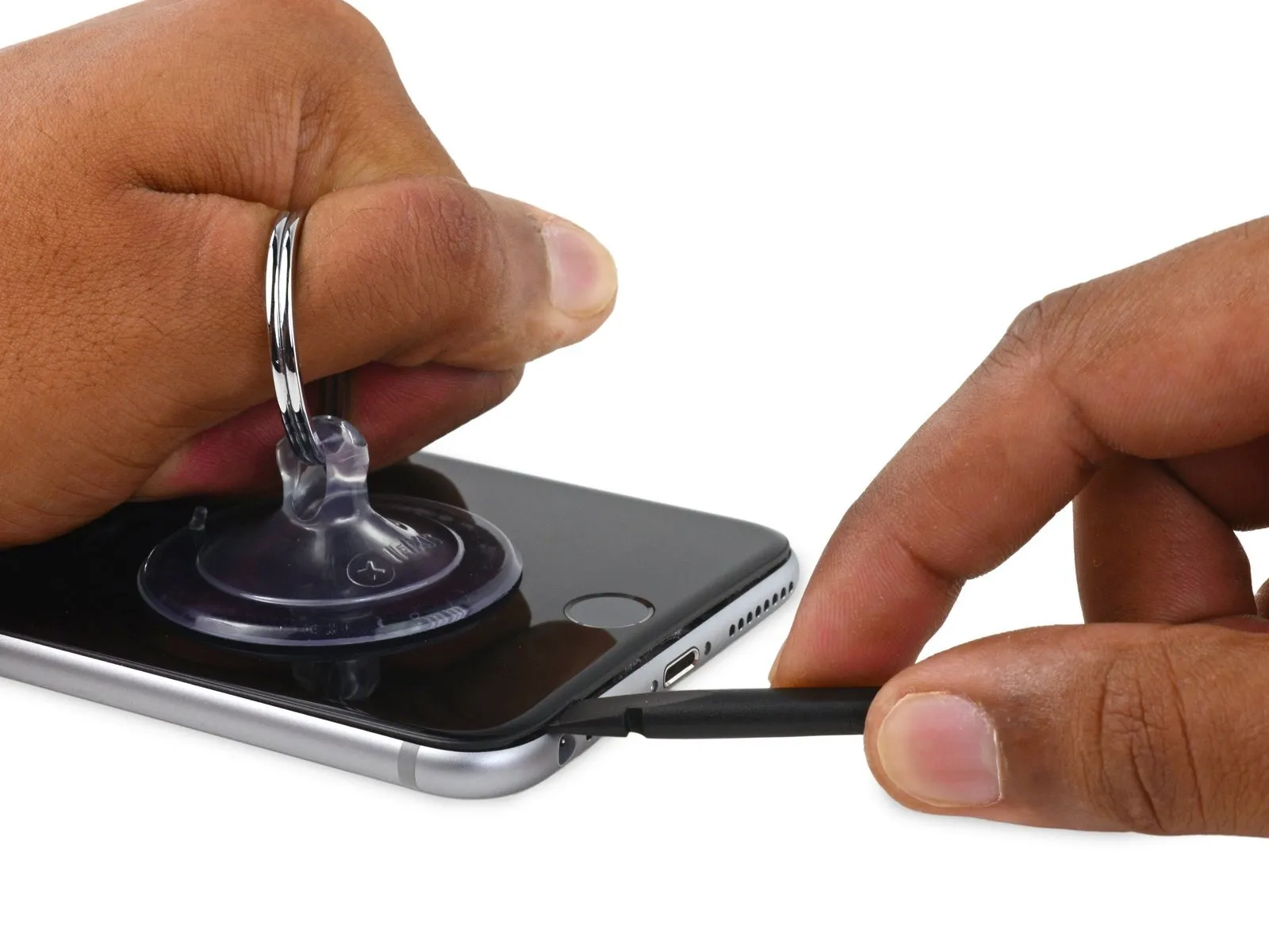
- To avoid damage, begin separating the front panel by gently inserting a prying tool into the indentation located directly over the headphone jack.
- Using consistent suction cup pressure, carefully slide the spudger's flat tip into the separation between components, positioning it directly over the headphone jack.
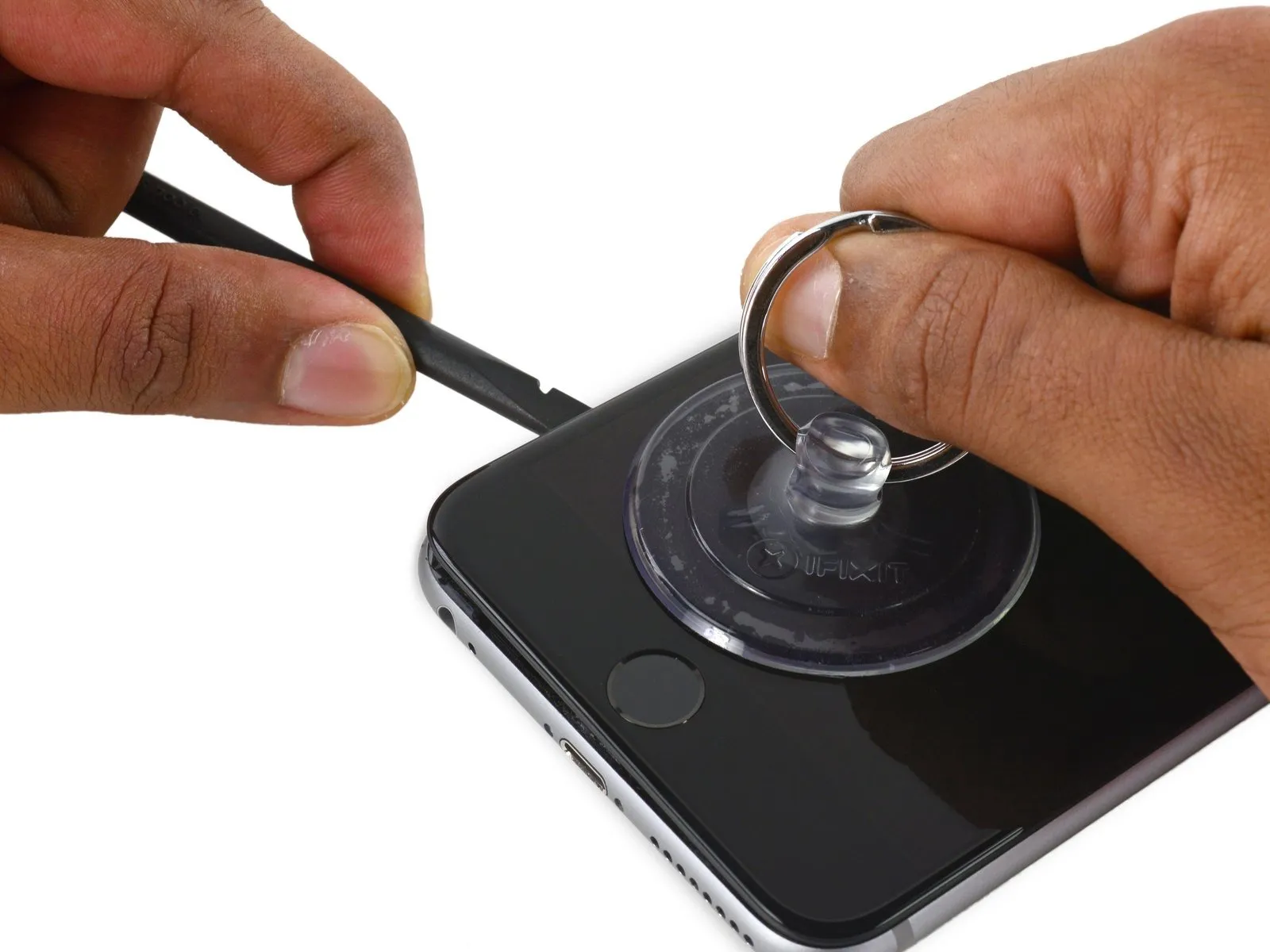
Step 8
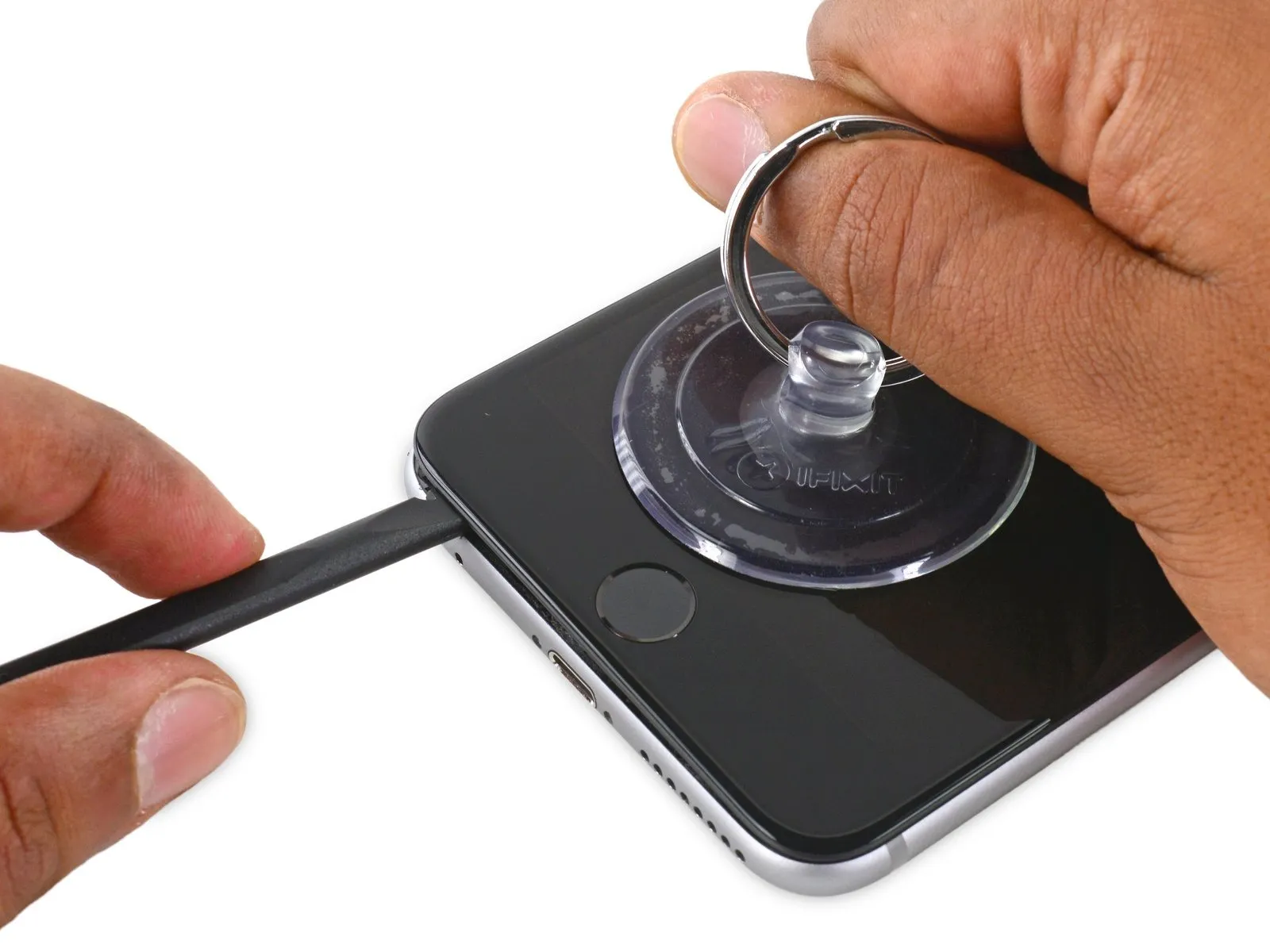
- Using a spudger, gently increase the space separating the front panel from the rear case.
Step 9


Step 10
Step 11


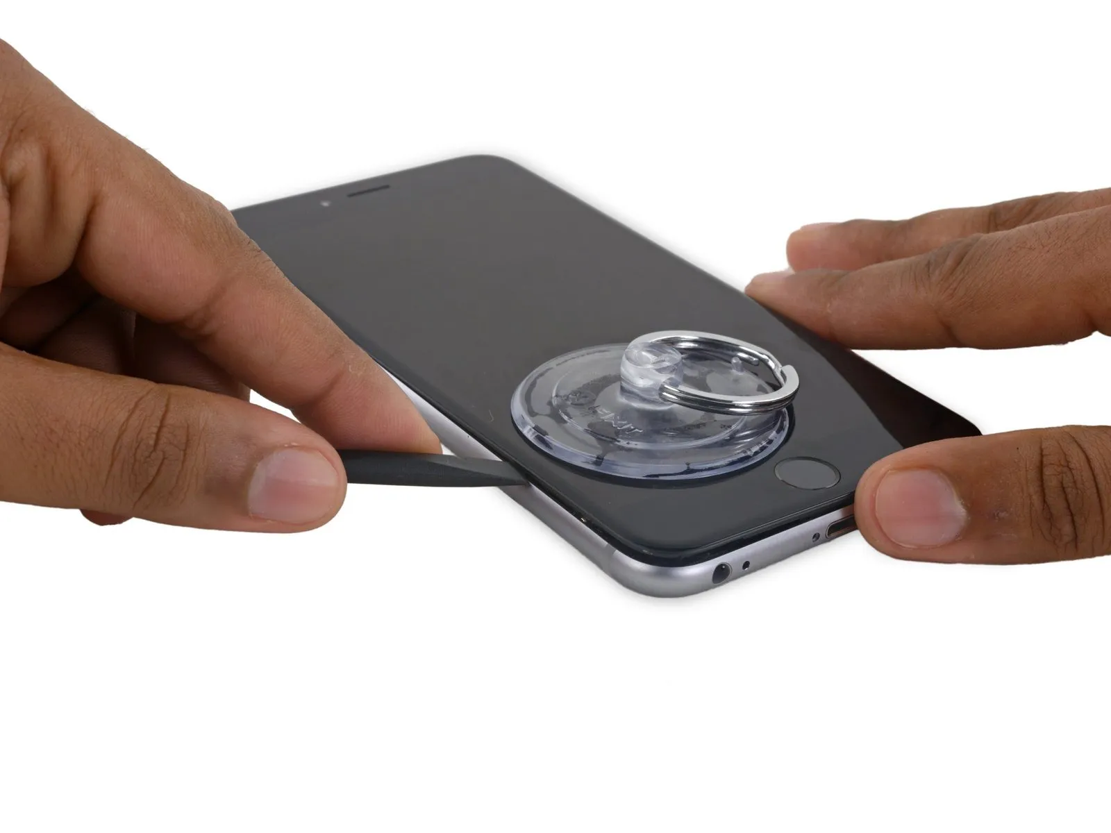
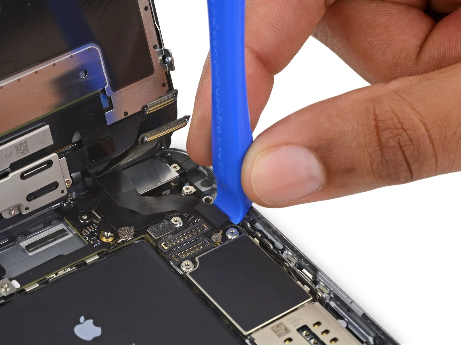
- Using a screwdriver with a flat head, carefully slide the tip into the slot.Use a plastic pry tool, often referred to as a spudger.Locate the display's right side.
Carefully move theUse a plastic spudger.Raise the component along the right-hand vertical plane.
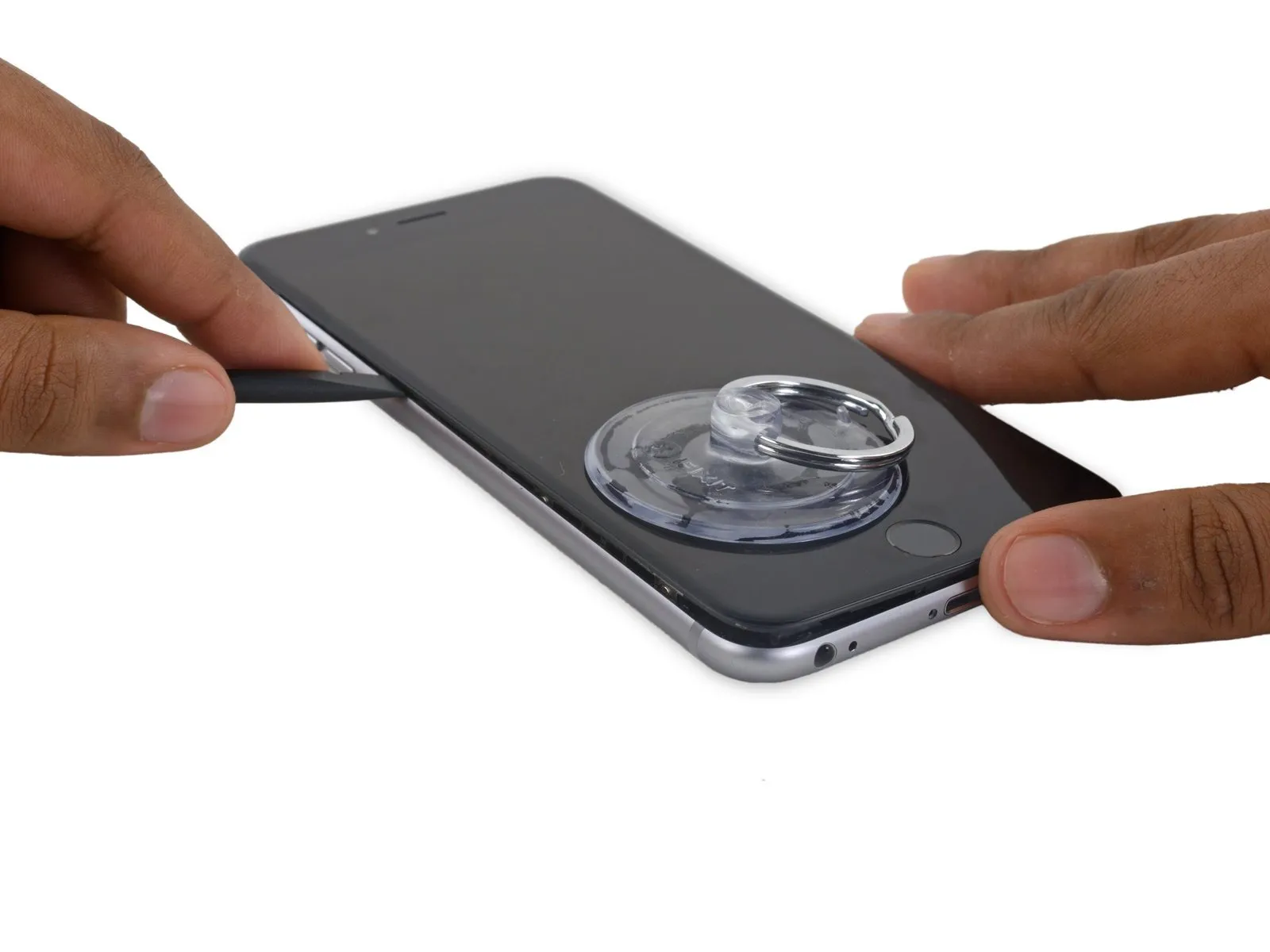
Step 12


- Employ a 3/8-inch socket wrench to tighten the fastener to a torque of 15 Nm, ensuring you observe all safety precautions regarding eye protection and handling of the component.Use a plastic pry tool.Maintain pressure on the rear case while lifting with the suction cup to release the phone.
Carefully avoid detaching the display assembly entirely, as doing so risks harming the delicate data cables located along the iPhone's upper edge.
Step 13

- To detach the suction cup, lift the small protrusion located on its surface.
Step 14

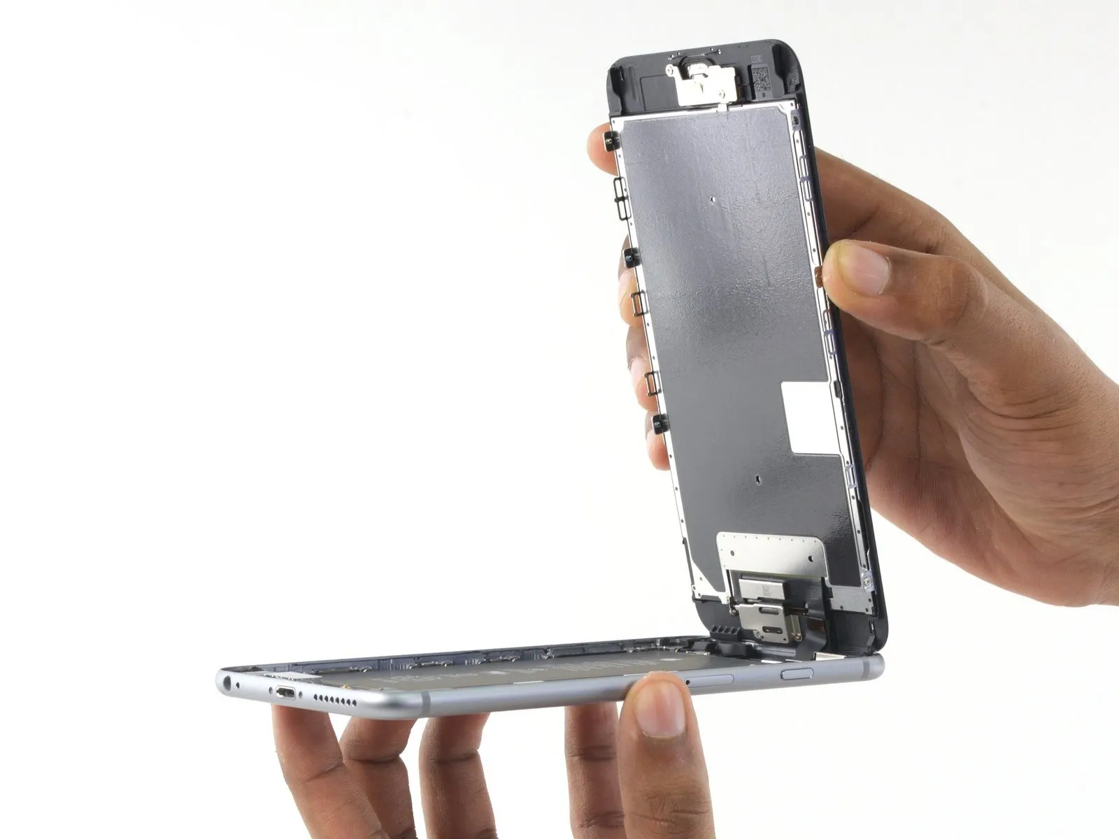

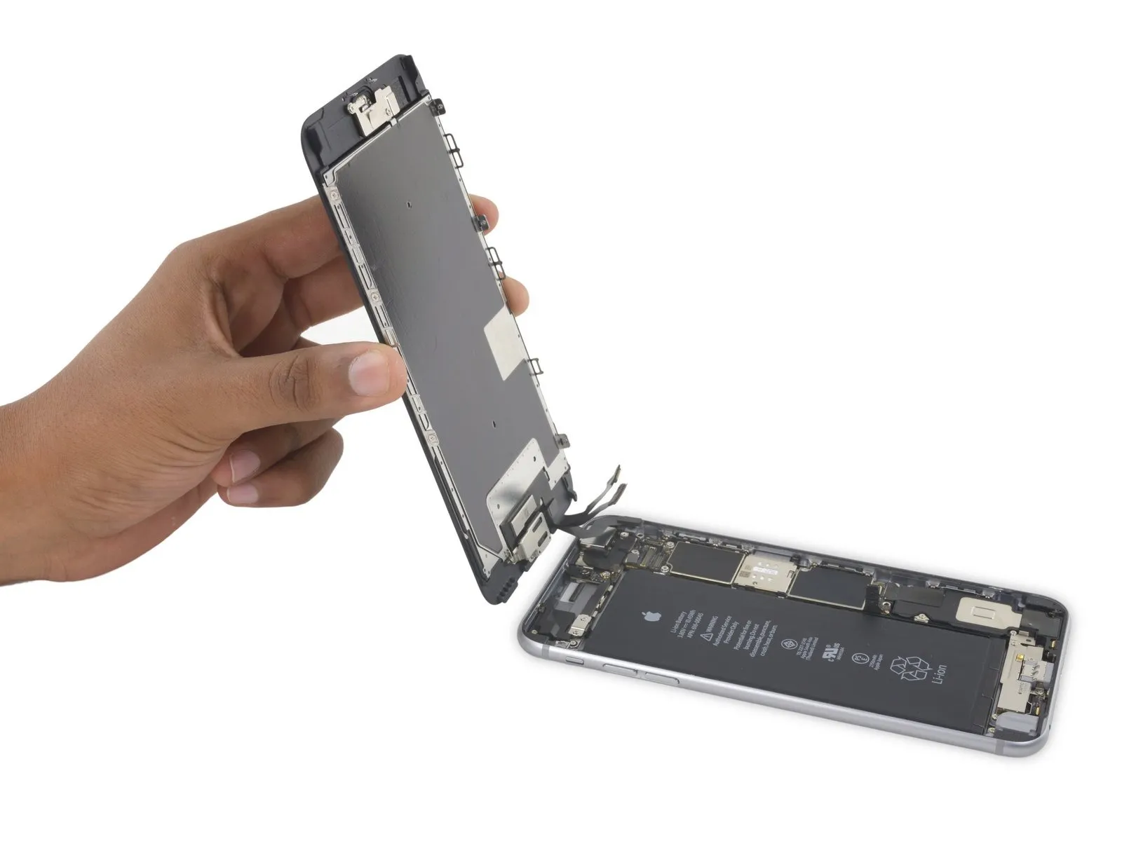
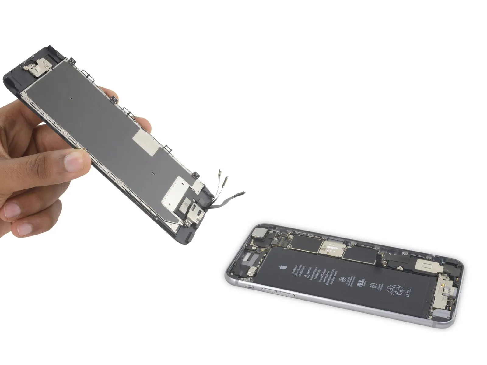
- Using the upper front panel's clips as a pivot point, carefully raise the display assembly to separate the phone's housing.
Carefully position the display at a roughly 90-degree angle, then secure it in a supported position to prevent movement during the repair process.
To prevent damage, limit the display's opening angle to a maximum of 90 degrees, as it remains connected to the phone's upper section via the display cable, digitizer cable, and front camera cable—these are susceptible to tearing.
To avoid stressing the display's wiring during the repair process, secure it with a rubber band.
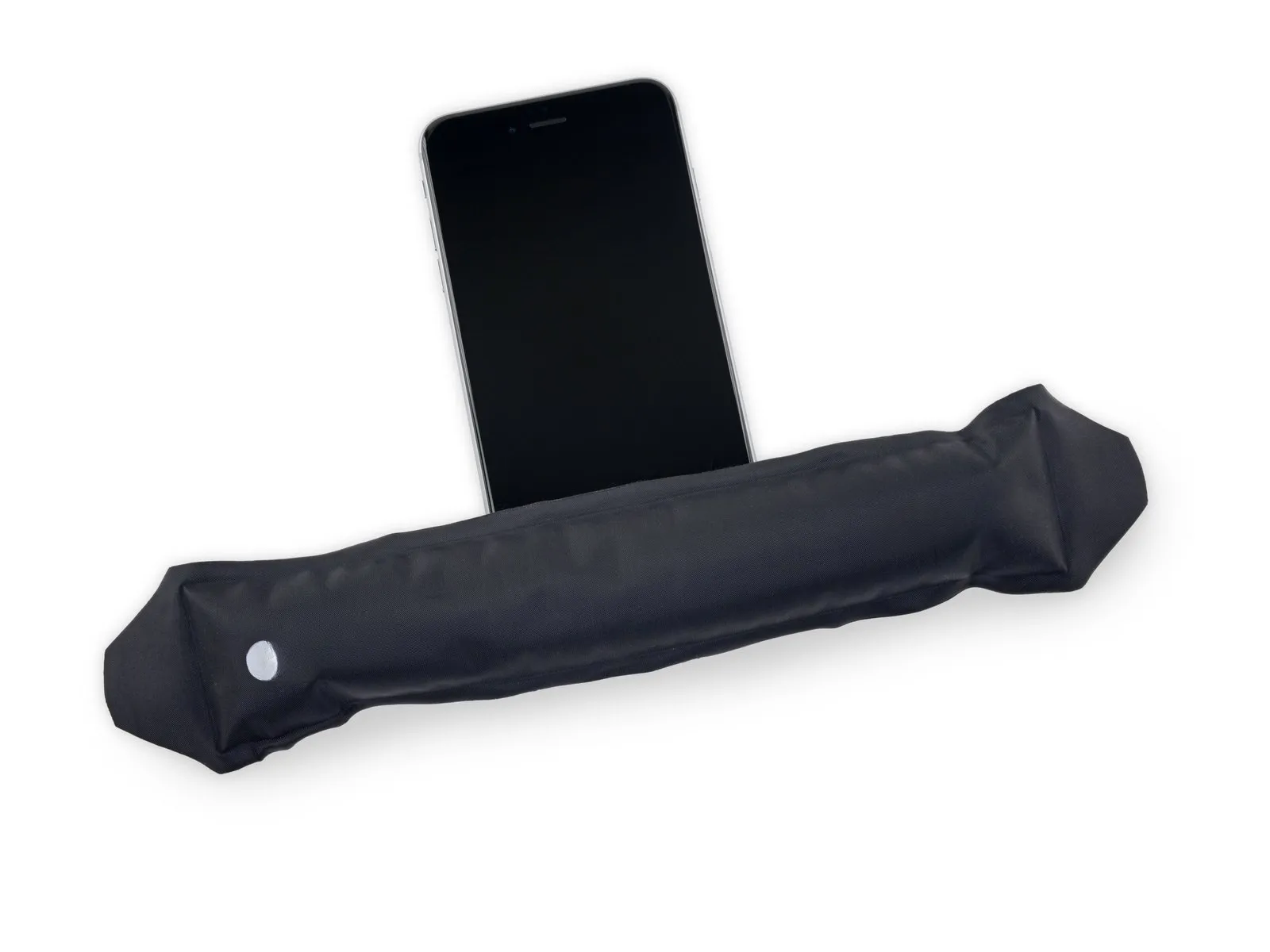
As a temporary measure, an unopened standard-sized canned drink can provide the necessary support for the display.
Step 15 | Battery Connector
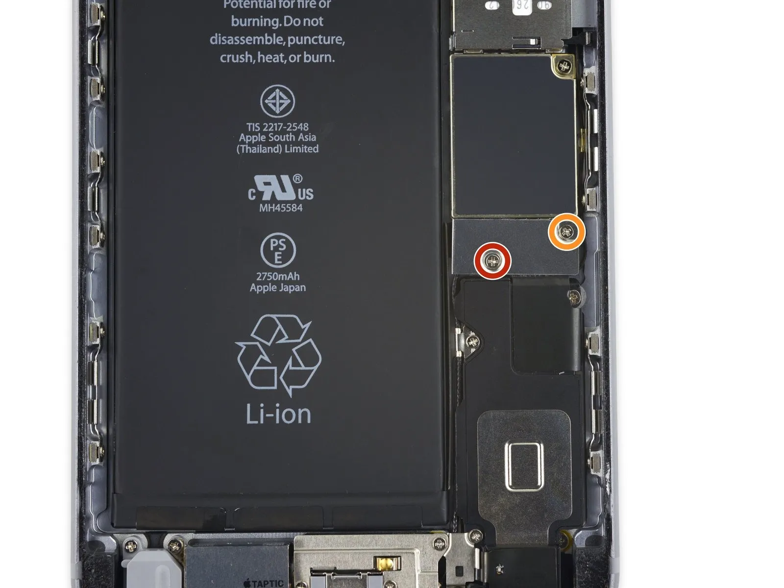
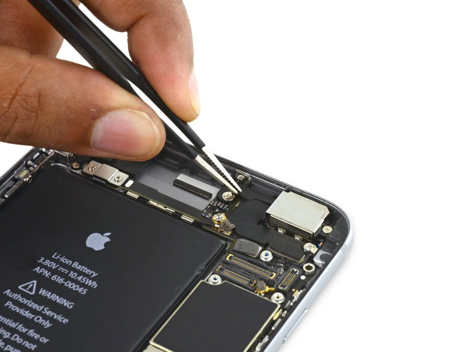
- Using a Phillips screwdriver, detach the battery connector bracket from the logic board by unscrewing the two fasteners. These screws measure the specified lengths.
Begin the process with a single unit.Use a 2.9-millimeter screw.
Begin the process with a single unit.Use a 2.3-millimeter screw.
To prevent irreversible damage, meticulously organize all screws during disassembly, ensuring they are returned to their original locations during reassembly.
Step 16
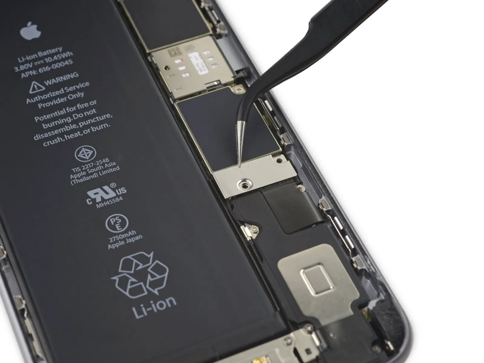
Using a 1/4-inch wrench, detach the bracket securing the battery connector.
Step 17

Employ a 3/8-inch socket wrench to tighten the fastener to a torque of 15 Nm, ensuring the specified torque is achieved to prevent damage and maintain secure attachment.Use a plastic pry tool, often referred to as a spudger, to avoid scratching surfaces.Carefully detach the battery connector from the logic board by applying upward pressure with a clean fingernail or a similar tool, ensuring it disengages squarely.
Step 18


To prevent unintended activation, carefully reshape the connector and then test the iPhone's power functionality during the repair process.
Step 19 | Display Assembly
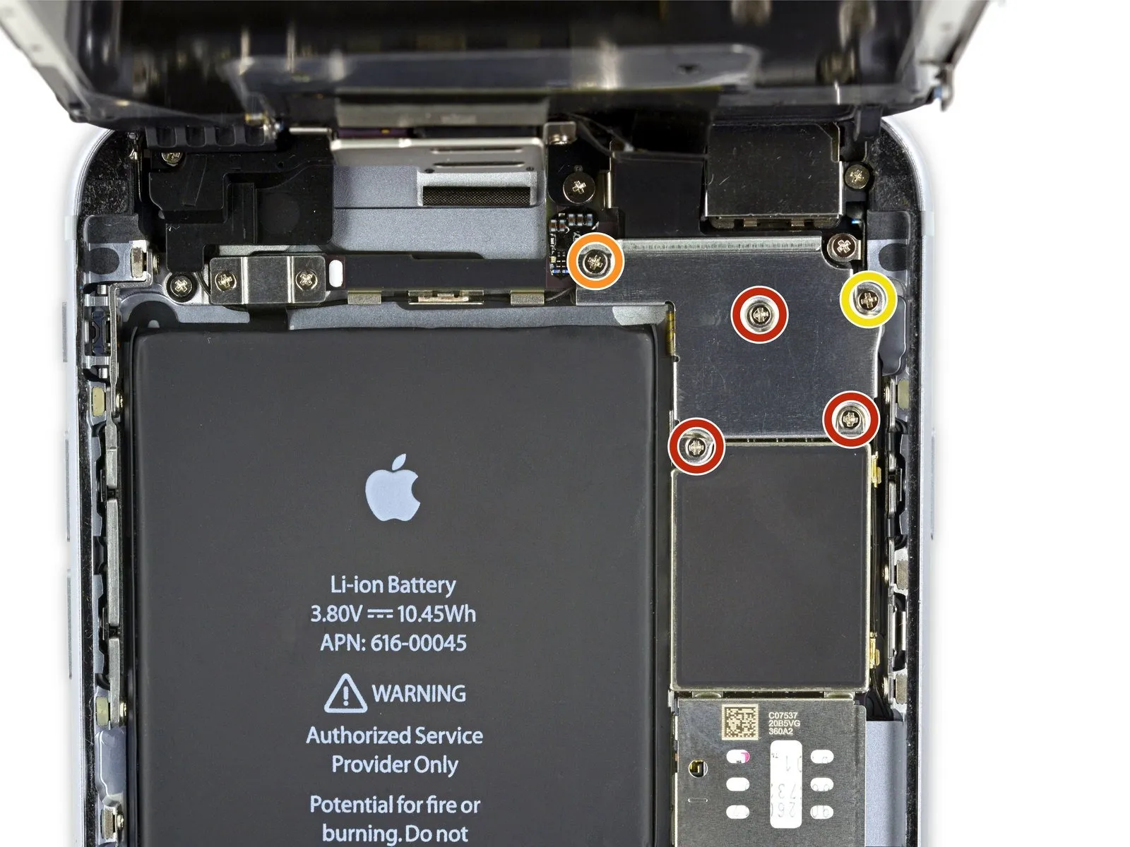
- Detach the listed components.Use a Phillips head screwdriver.:
- Use three screws, each measuring 1.3 millimeters.
- A screw with a 1.6 mm diameter is required.
- A single screw, measuring 3.0 millimeters, is required.
Ensure proper alignment and secure installation of this component during the reassembly process.Use a 3.0 mm screw.Position the component precisely within the bracket's upper-right quadrant to prevent logic board damage.
Step 20
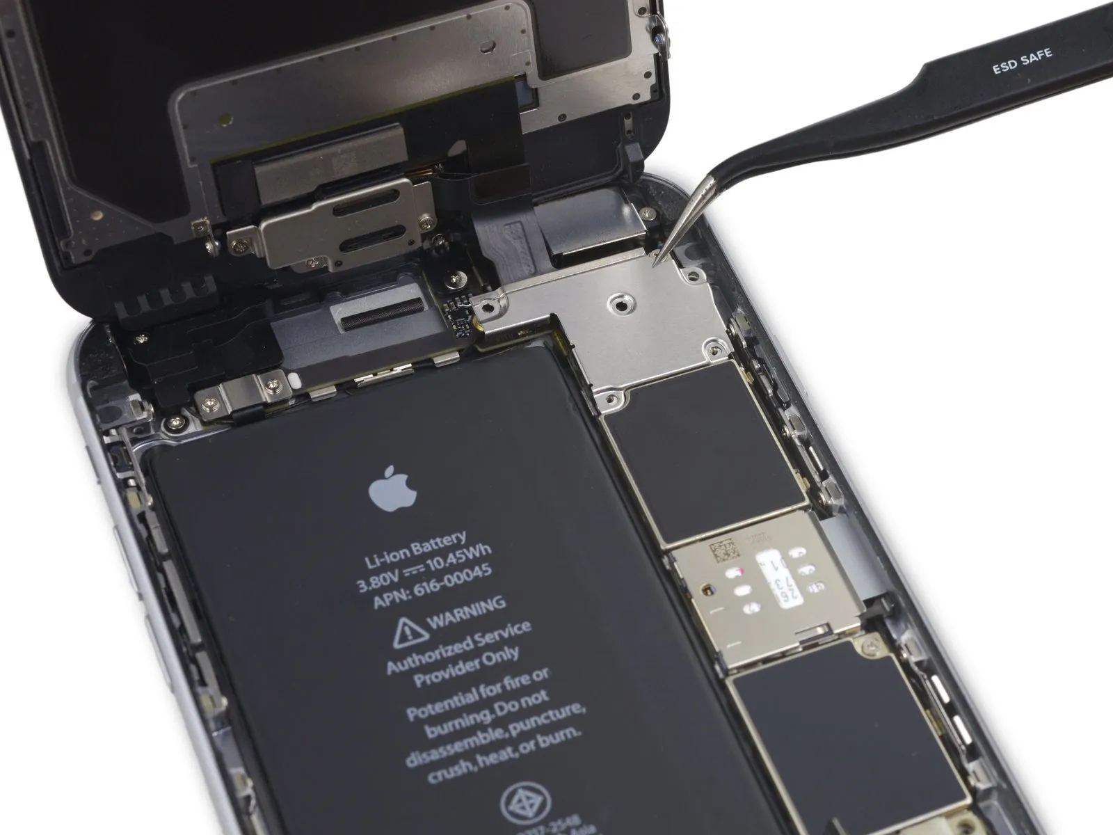

Using a T4 Torx screwdriver, detach the bracket securing the display cable.
Step 21

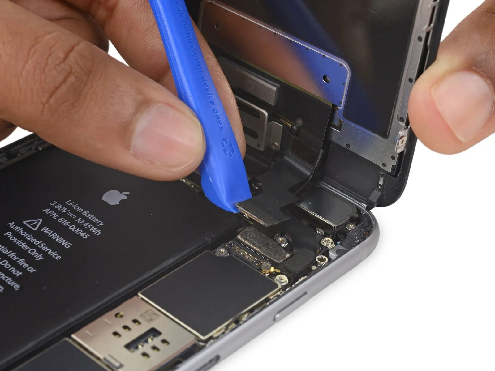
- Avoid applying force to the logic board socket while releasing the connector; focus solely on the connector's release mechanism.
- Employ a 3/8-inch socket wrench to securely tighten the fastener to a torque of 15 Nm, ensuring no damage occurs to the surrounding components and observing all safety precautions.Use a plastic pry tool.Carefully separate the front camera and its associated sensor's cable connector.
Step 22
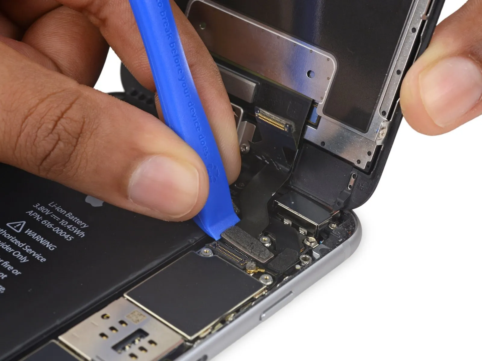

- Employ a 3/8-inch socket wrench to tighten the fastener to a torque of 15 Nm, ensuring you observe all safety precautions and handle the component with care.Use a plastic pry tool.Using a prying tool, carefully lift the digitizer cable directly upward to release it from its connector on the logic board.
- To ensure proper alignment and prevent damage, apply pressure to opposing ends of the digitizer cable connector during reconnection; avoid central pressure, as this may warp the component.The display's touch functionality is impaired due to damage to the digitizer..
Step 23

- Prior to either detaching or reattaching the cable in this procedure, ensure the battery is disconnected.
- Using a prying tool, carefully release the home button/fingerprint sensor cable by lifting it vertically from its connector on the logic board.
Step 24
- Carefully detach the display assembly, ensuring no damage occurs.
- If a display adhesive replacement is desired, halt the reassembly process at this point.
Step 25 | iSight Camera

Step 26
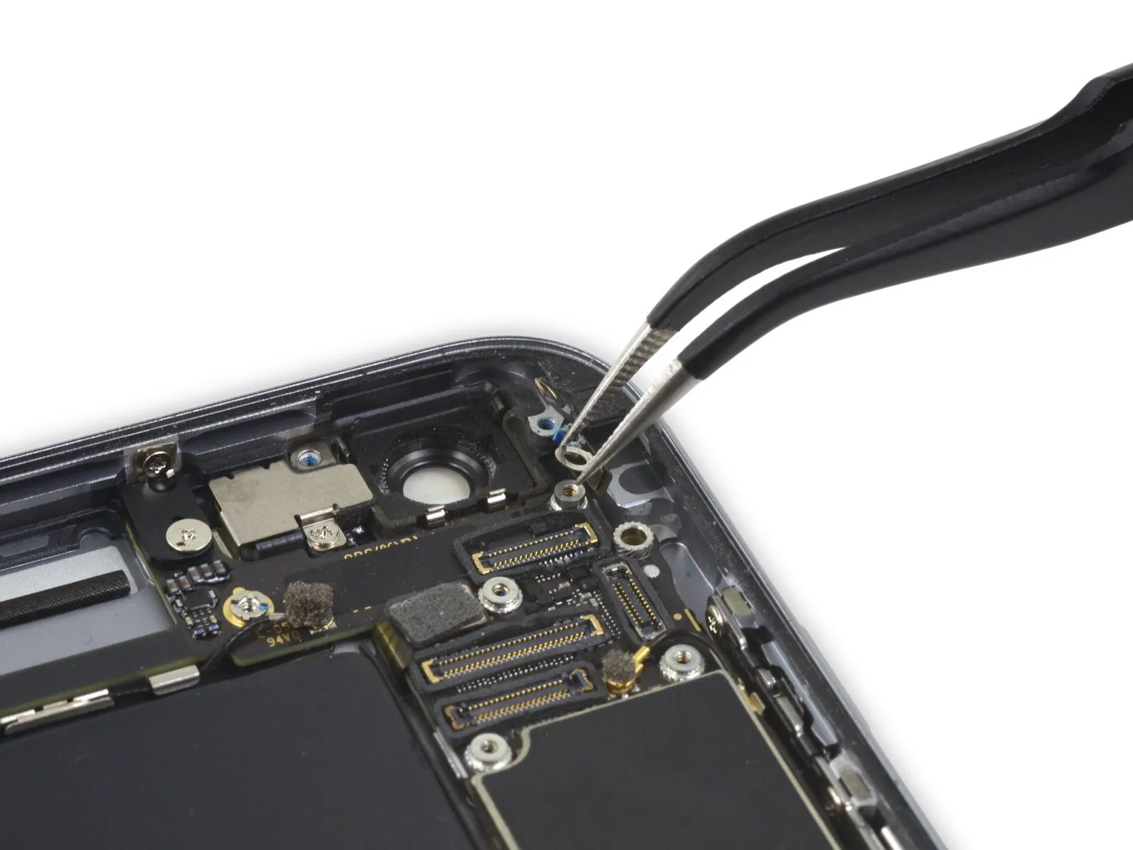
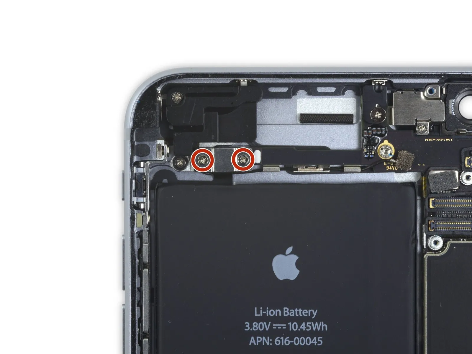
- Using a Phillips screwdriver, detach the screws located above the camera bracket.
- A single screw, measuring 1.9 millimeters, is required.
- A screw with a 2.4-millimeter head diameter is required.
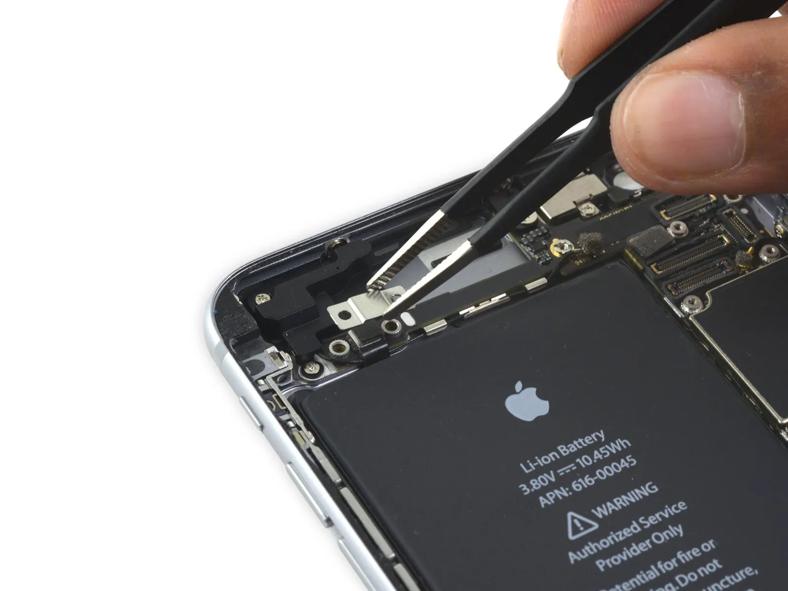
Step 27
Step 28
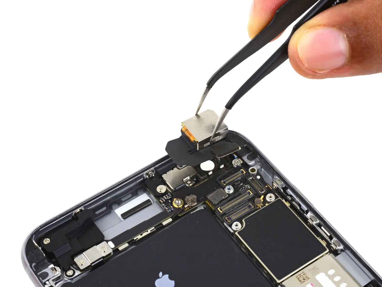
- Carefully detach the iSight camera connector from the socket located on the logic board.
Carefully lift the connector, ensuring the socket remains secured to the logic board.
Step 29

- Using the tool's straight edge, carefully slide it into the designated space.Use a plastic pry tool, often referred to as a spudger, to gently separate components.Locate the space separating the iSight camera assembly from the rear casing.
- Using careful, controlled force, disengage the camera from its enclosure.
Step 30
- Carefully detach the iSight camera assembly.
Step 31 | SIM Tray


- Carefully position aUse the provided SIM ejection tool.Insert the SIM tray into its designated opening.
Using your thumbnail or a SIM ejection tool, push inward on the SIM tray until it releases.
Step 32

- Using a SIM ejection tool or a straightened paperclip, carefully extract the SIM card tray.
Ensure the SIM tray is positioned correctly during reinsertion, aligning it so the metallic contacts face downward.Use a specialized SIM ejection tool or a small, straightened paperclip to depress the SIM card release button located within the designated aperture.The component is located on the lower surface.
Step 33 | Logic Board

- Detach the solitaryUse a Phillips screwdriver with a 1.4 mm tip.Secure the NFC bracket's position.
Step 34

- Detach the NFC bracket.
Step 35
- Detach the pair of screws.Use a Phillips screwdriver with a 2.7 mm tip.Affix the audio control cable bracket to the logic board, ensuring all technical specifications are met.
Step 36

Step 37

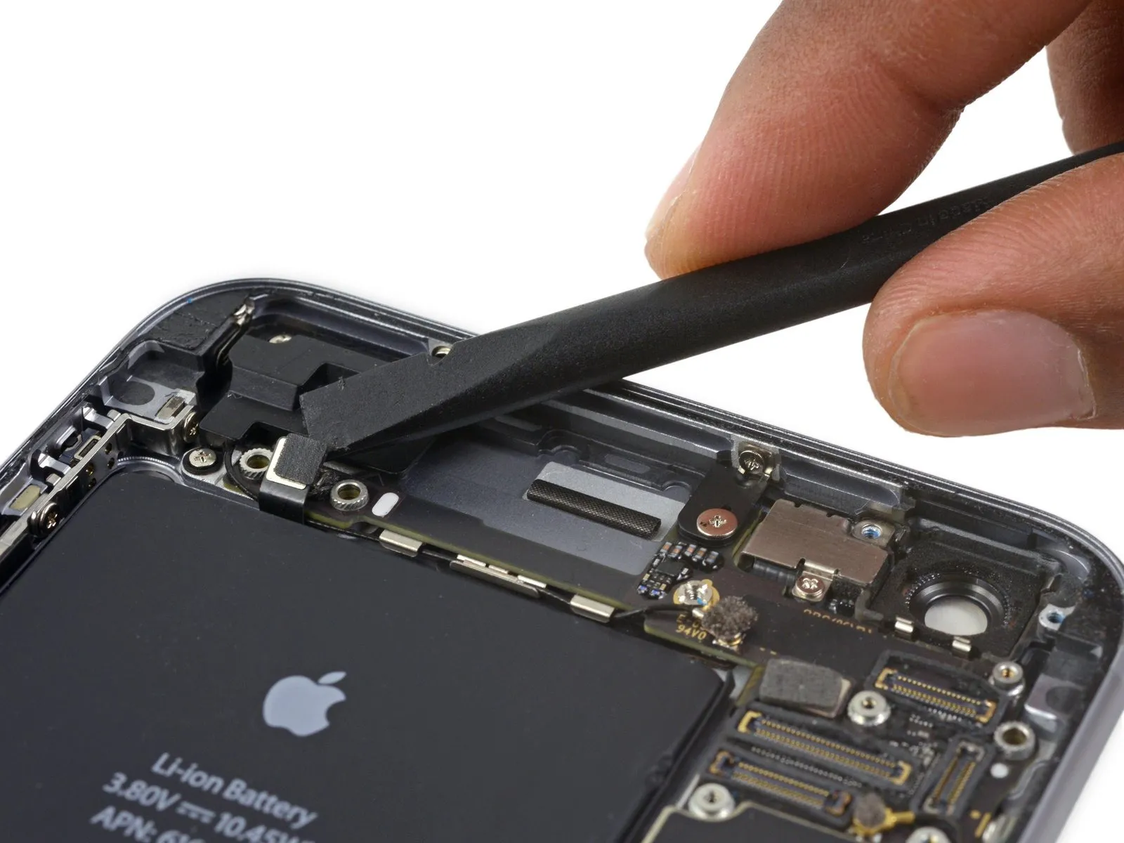
- Carefully separate theConnect the audio control cable.Carefully disengage the connector by applying upward pressure directly perpendicular to its socket on the logic board.
Step 38
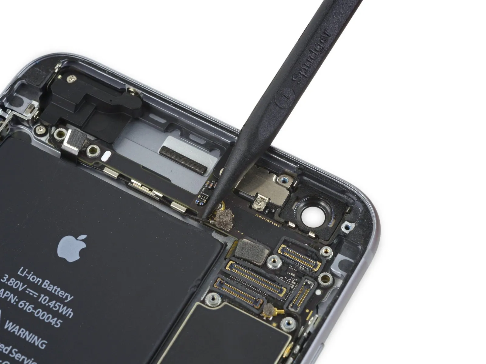
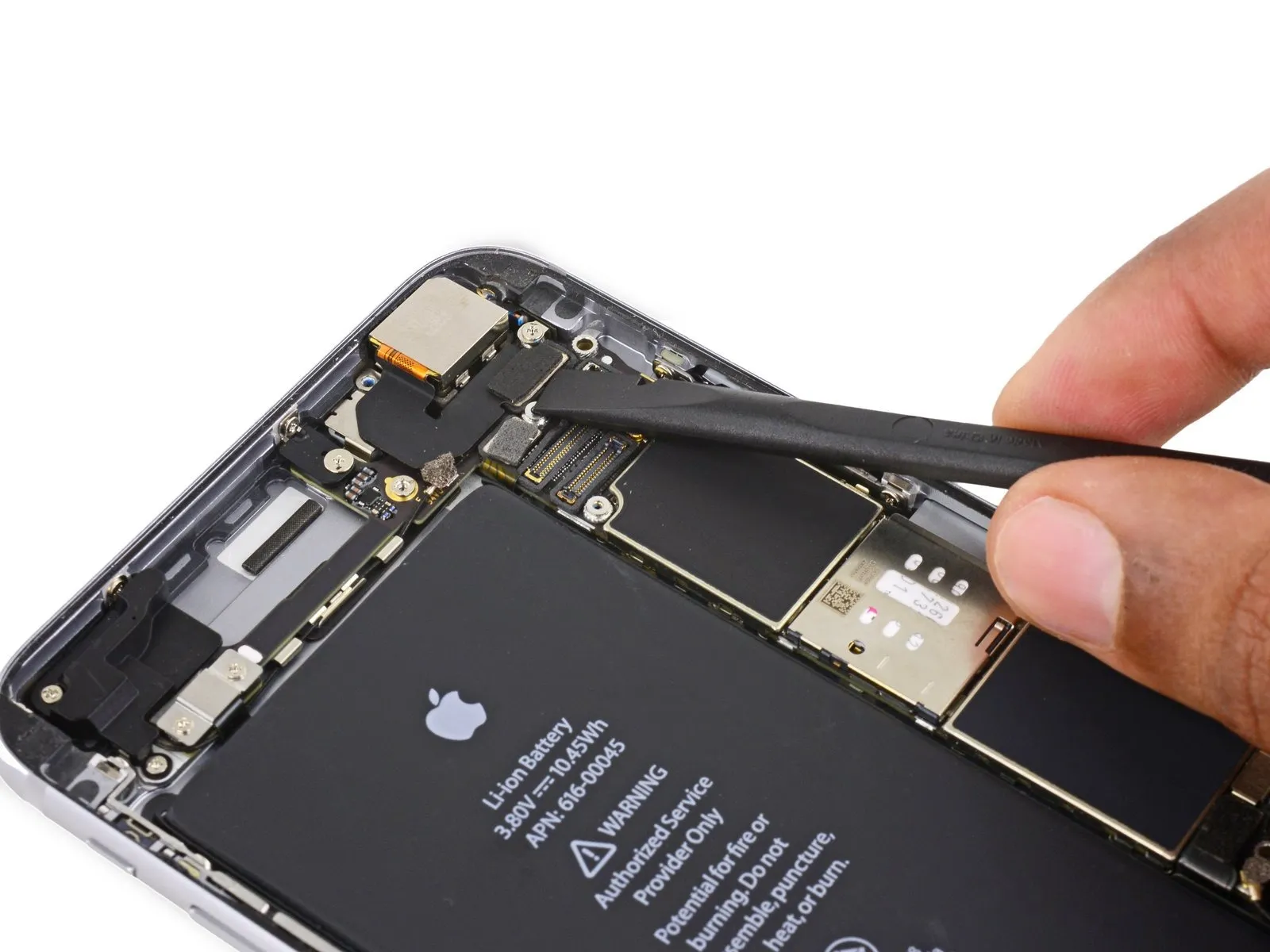
- Carefully detach theThe coaxial cable connecting to the cellular antennaCarefully detach the connector by applying upward pressure, ensuring it disengages vertically from its corresponding socket on the logic board.
Step 39

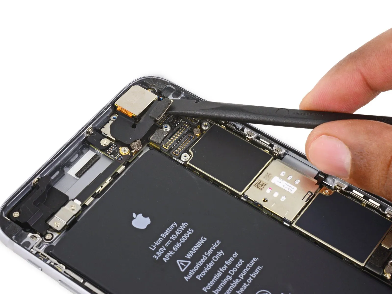
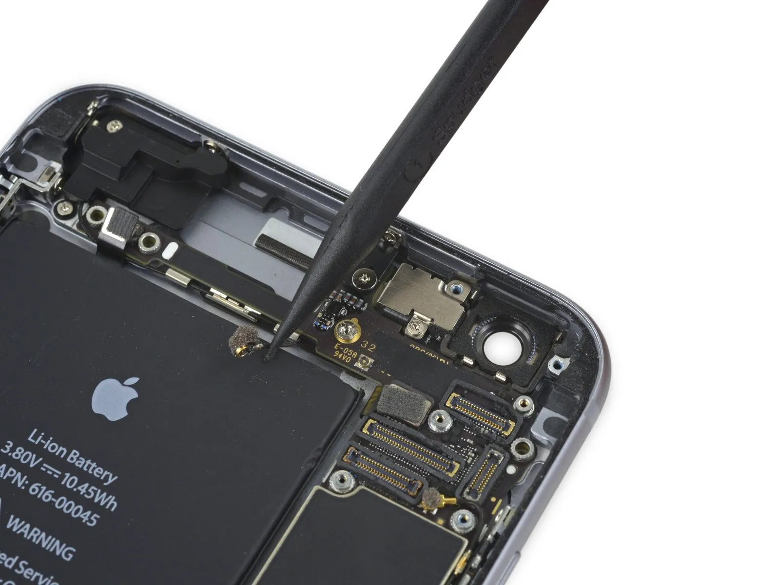
- Carefully detach theConnect the antenna cable to the Wi-Fi diversity antenna.Carefully lift the connector away from the logic board.
Step 40

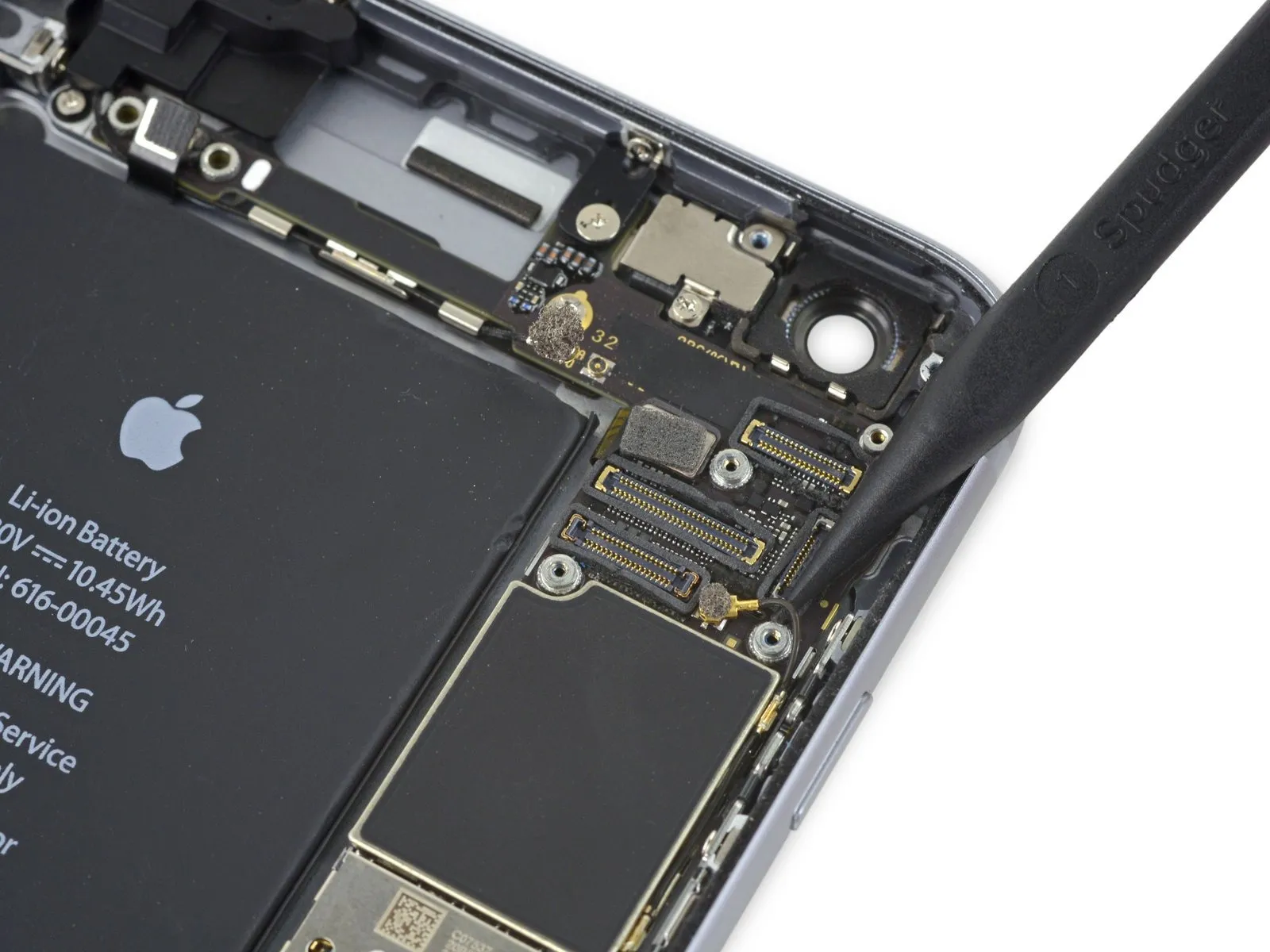
- Carefully detach theThe flexible cable connecting the power button to the device's mainboard.Carefully detach the component from its corresponding receptacle on the circuit board.
Step 41
Step 42
Step 43

Step 44
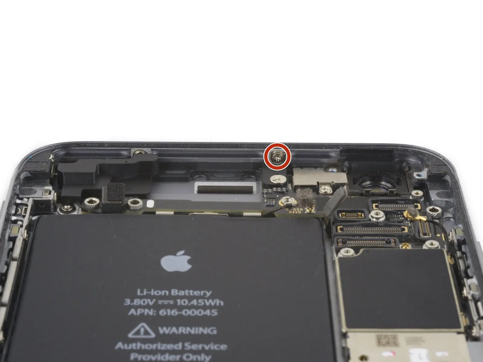

- Using the appropriate screwdriver, detach the listed screws.
Use a Phillips screwdriver to remove a single screw with a 1.3 mm head.
Use a Phillips screwdriver to remove a screw with a 2.6 mm head.
A screw with a 2.2-millimeter diameter is required. - To detach standoff screws, utilize a standoff screwdriver or bit designed for the task.
- If a dedicated tool isn't available, a small flathead screwdriver can be carefully employed; however, exercise heightened vigilance to prevent slippage and potential harm to nearby parts.
Step 45
Step 46
Step 47
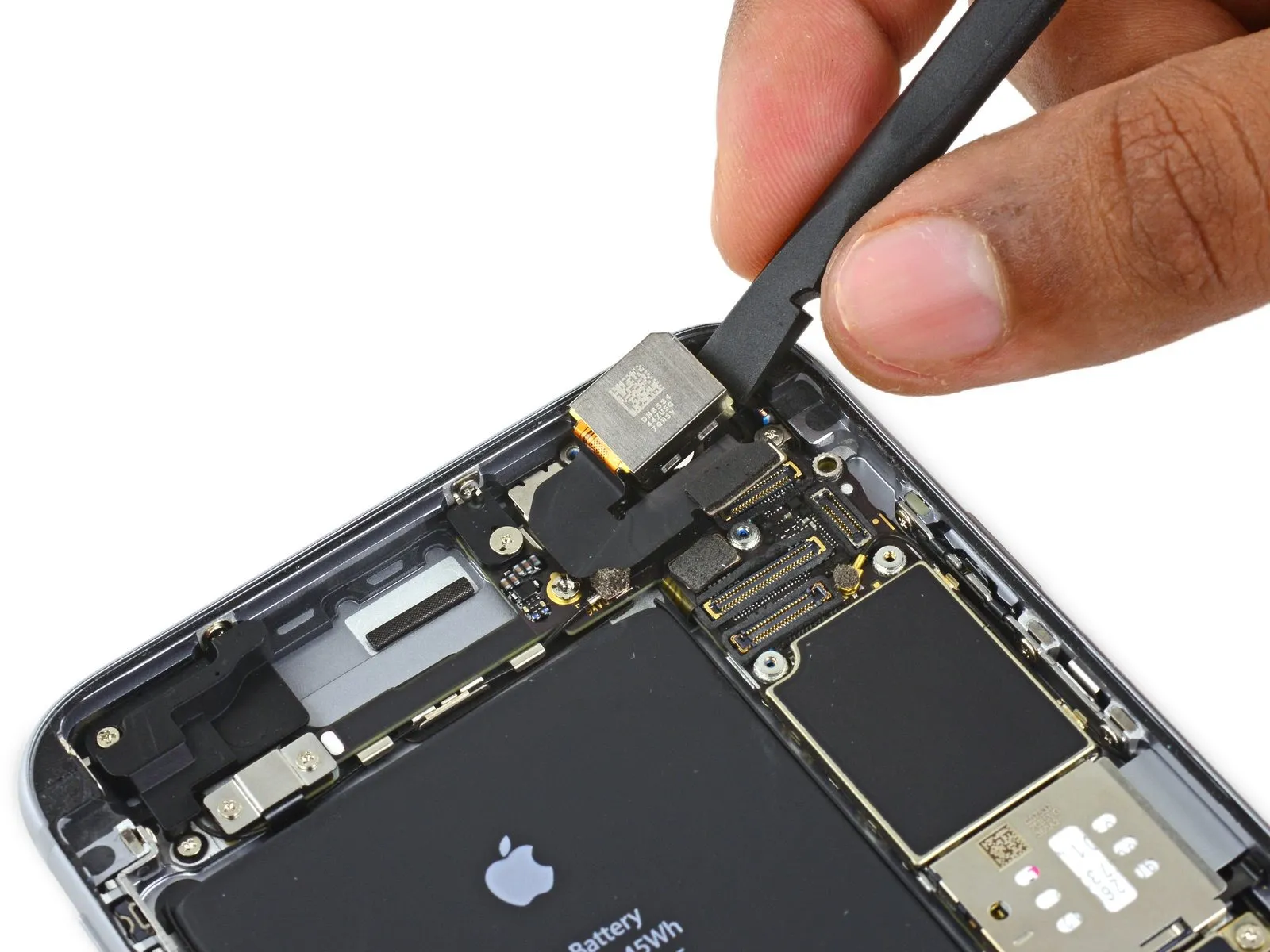
- Disconnect the cellular antenna cable from both the second and third logic board retaining clips.
- Carefully insert the tip of the tool into.Use a plastic pry tool, often referred to as a spudger.Carefully disengage the cellular antenna cable from its securing clip on the middle logic board, using gentle pressure.
- Avoid separating the component from its housing by applying traction to the wire, because doing so risks damaging it.
- To connect the cable to its corresponding socket on the logic board, position it initially over the board and then guide it below the audio control flex cable, following the visual example in the provided image.
Step 48
Step 49


Step 50
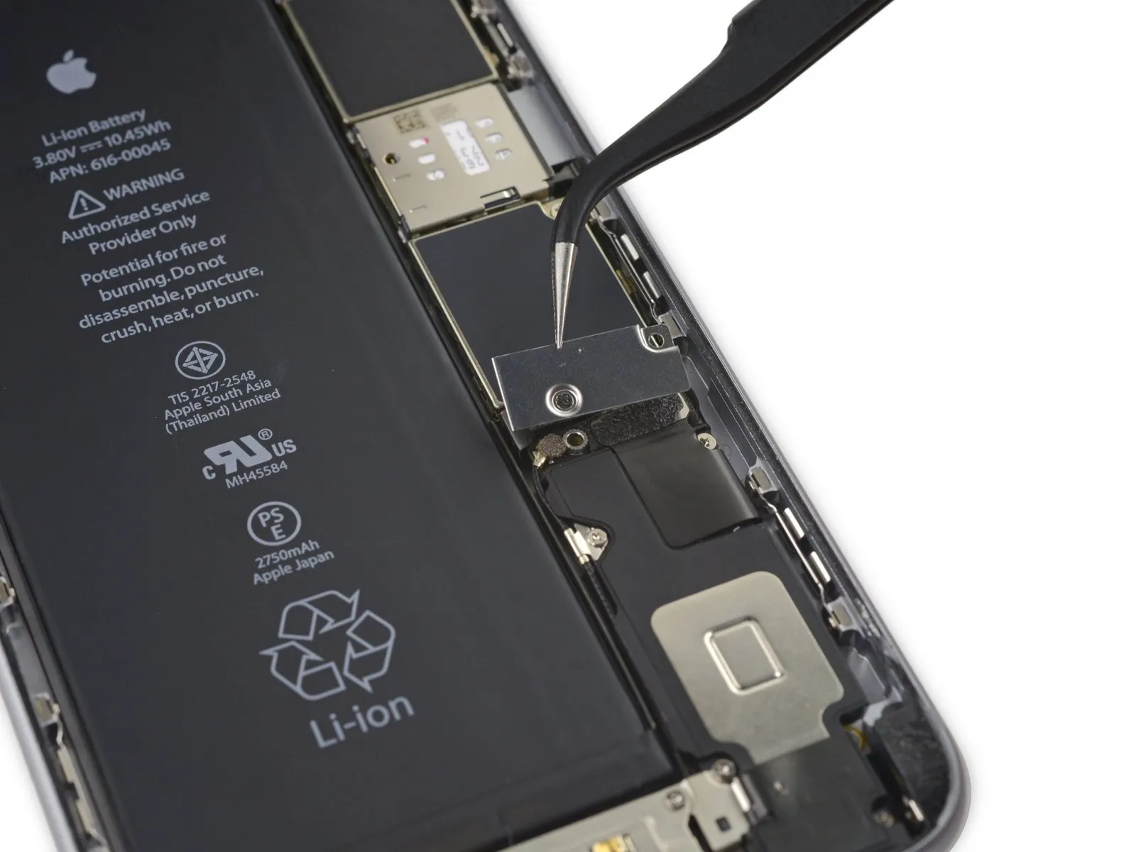
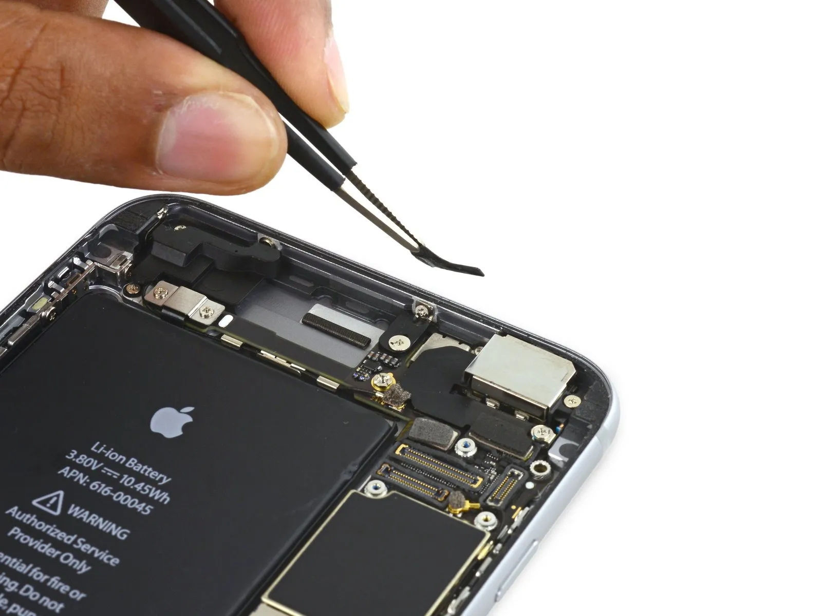
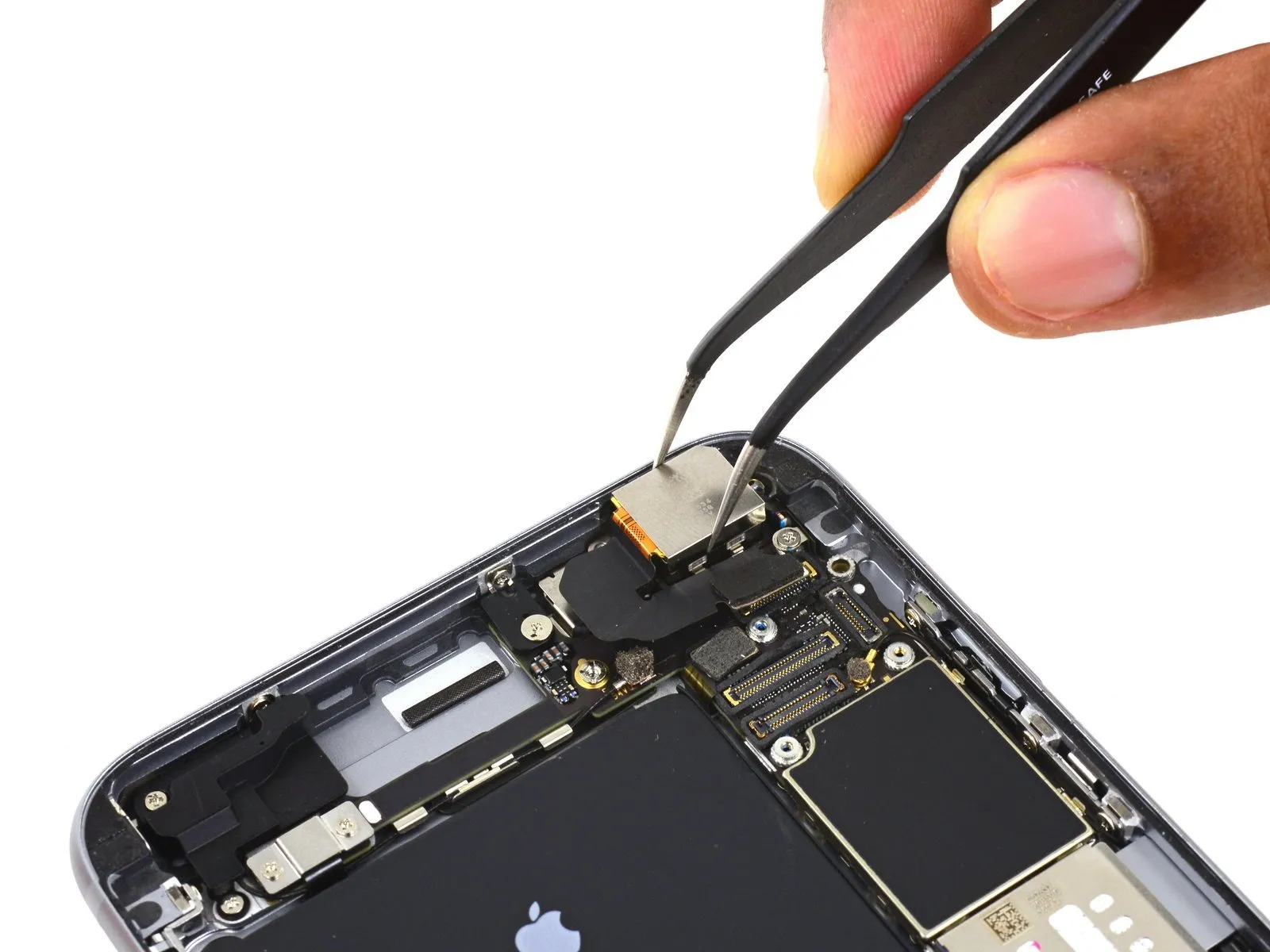
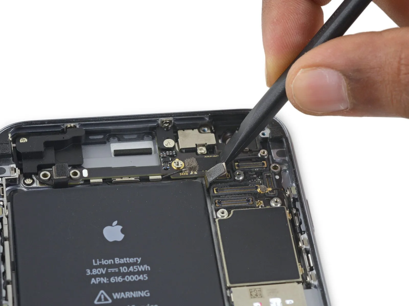
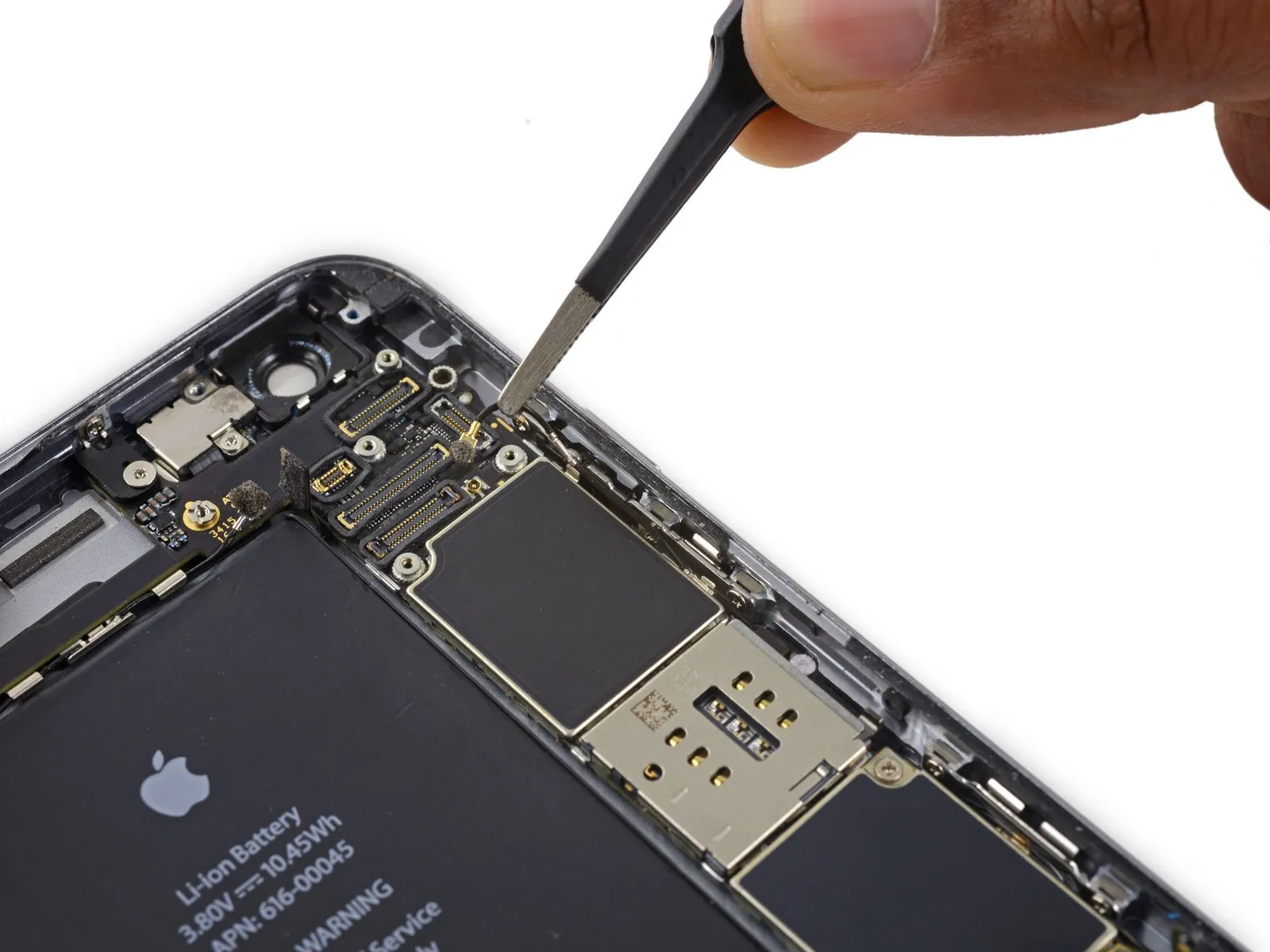
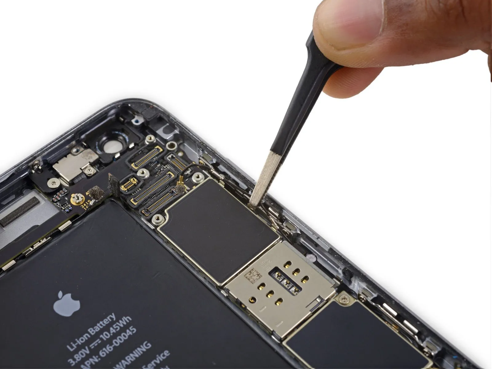
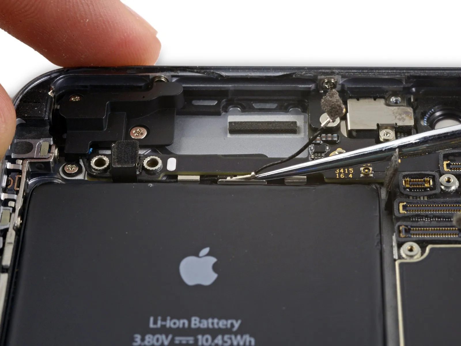
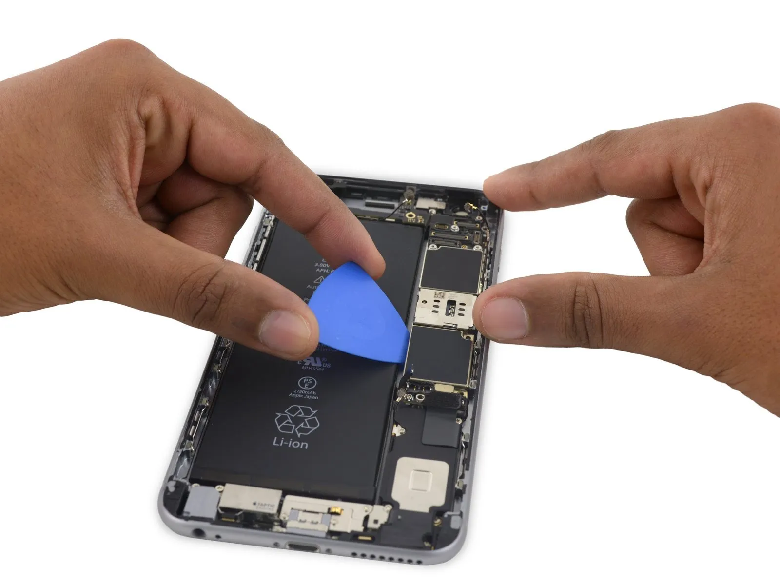
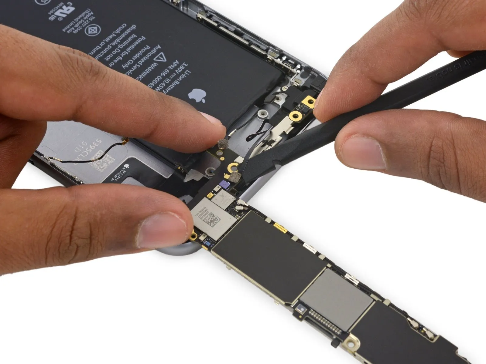
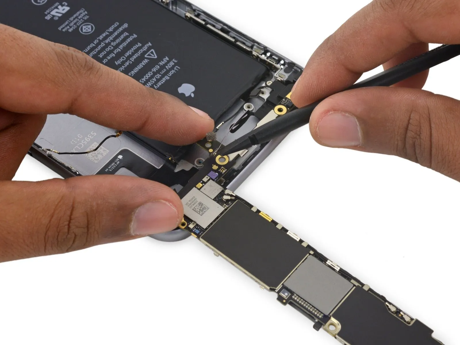
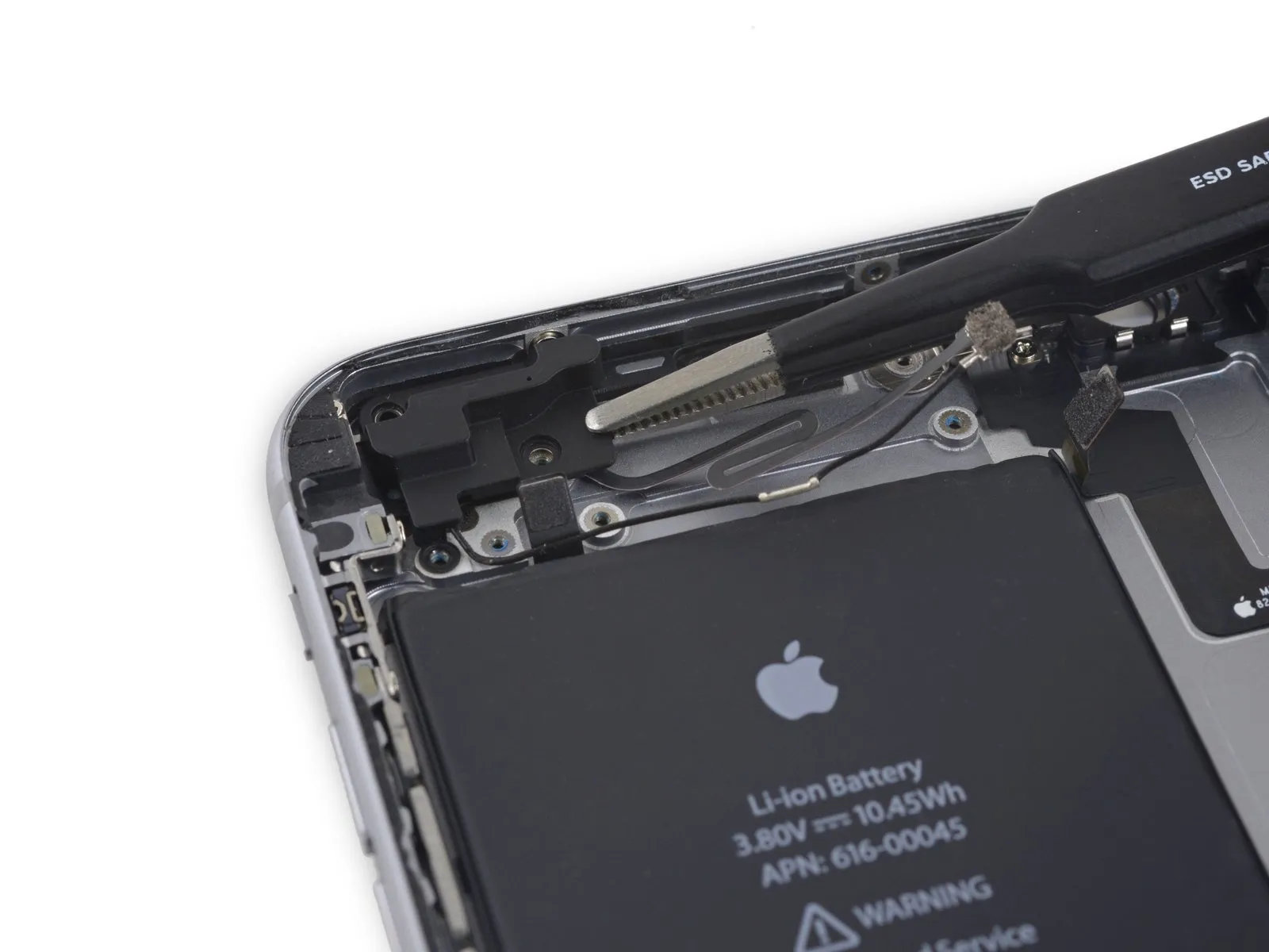
- To access the lone antenna connector, which is located on the bottom edge of the logic board close to the top, rotate the board so it stands upright.
- Disconnecting the Wi-Fi/Bluetooth antenna, which remains attached to the logic board's underside, prevents premature board removal.
Step 51
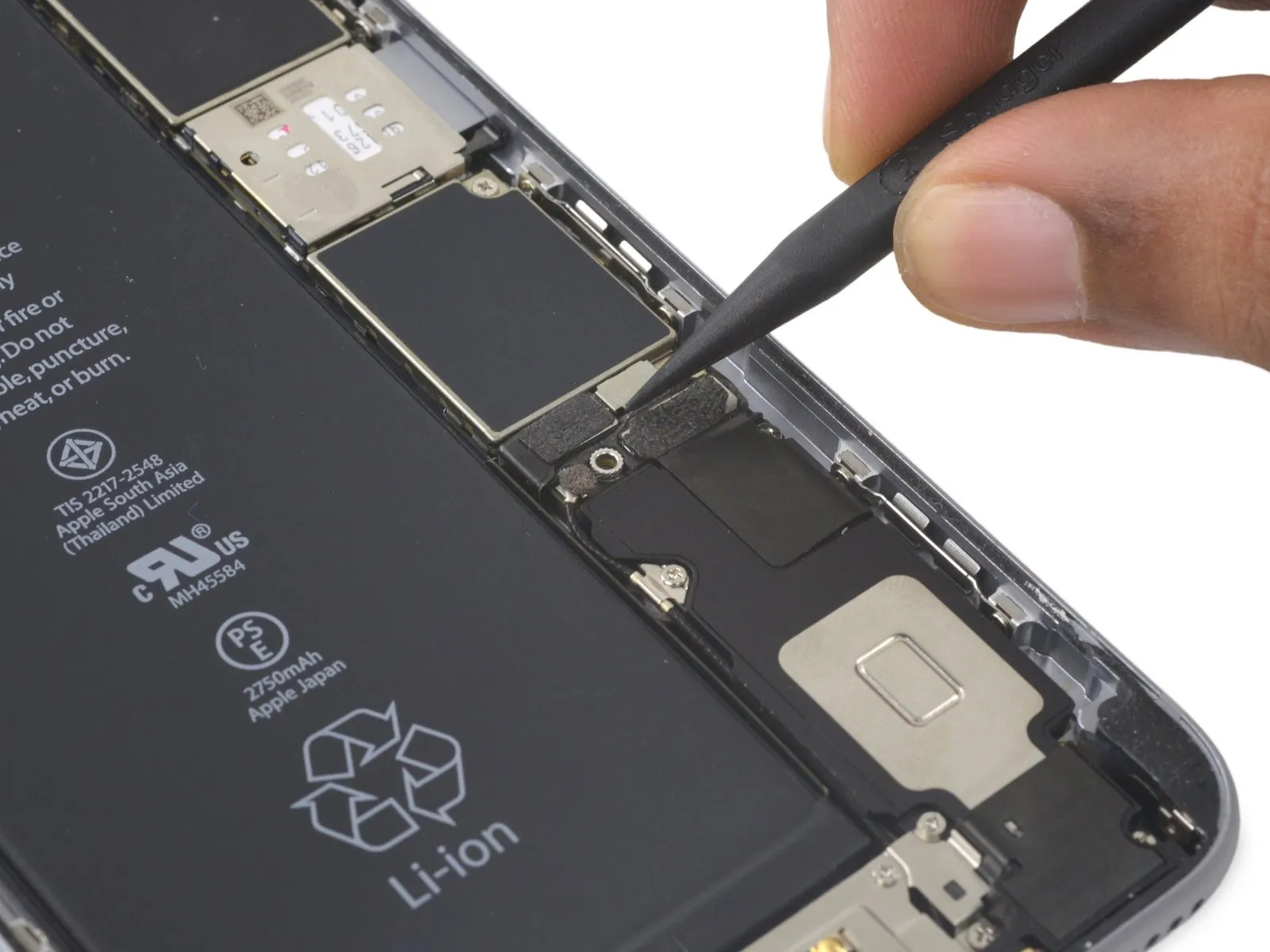
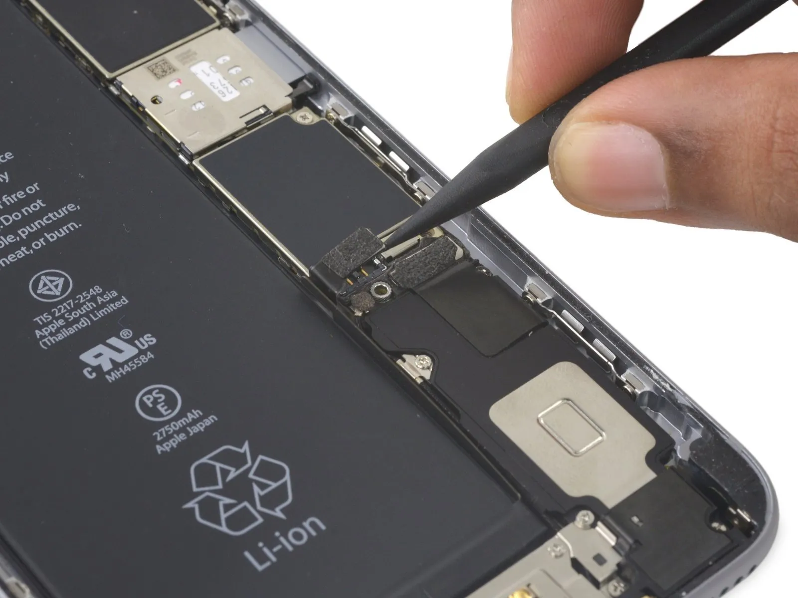
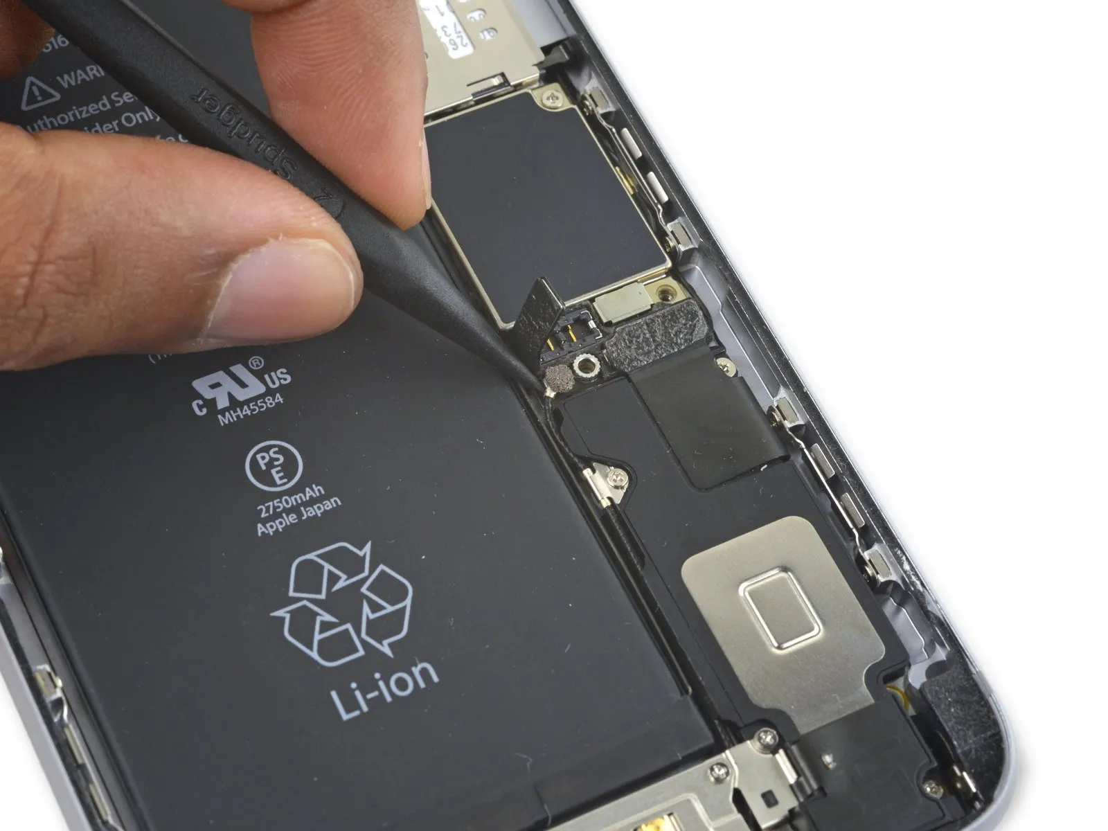
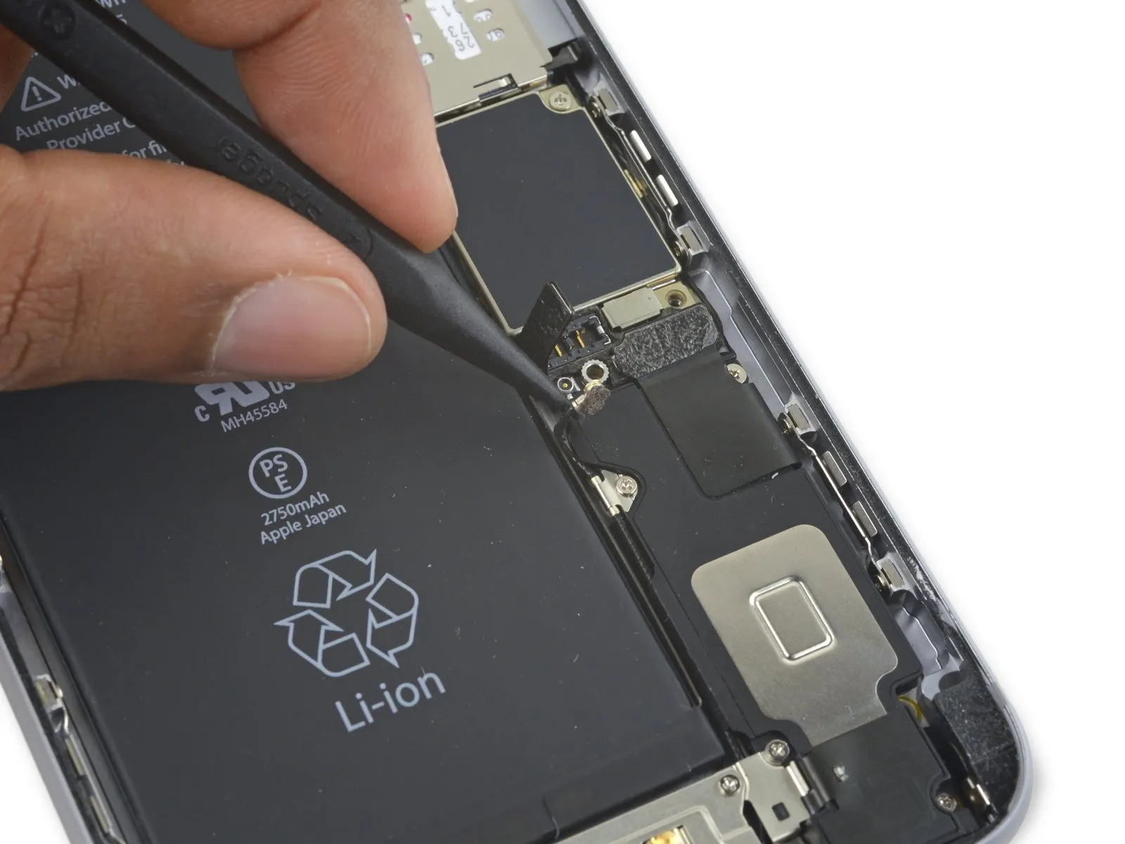
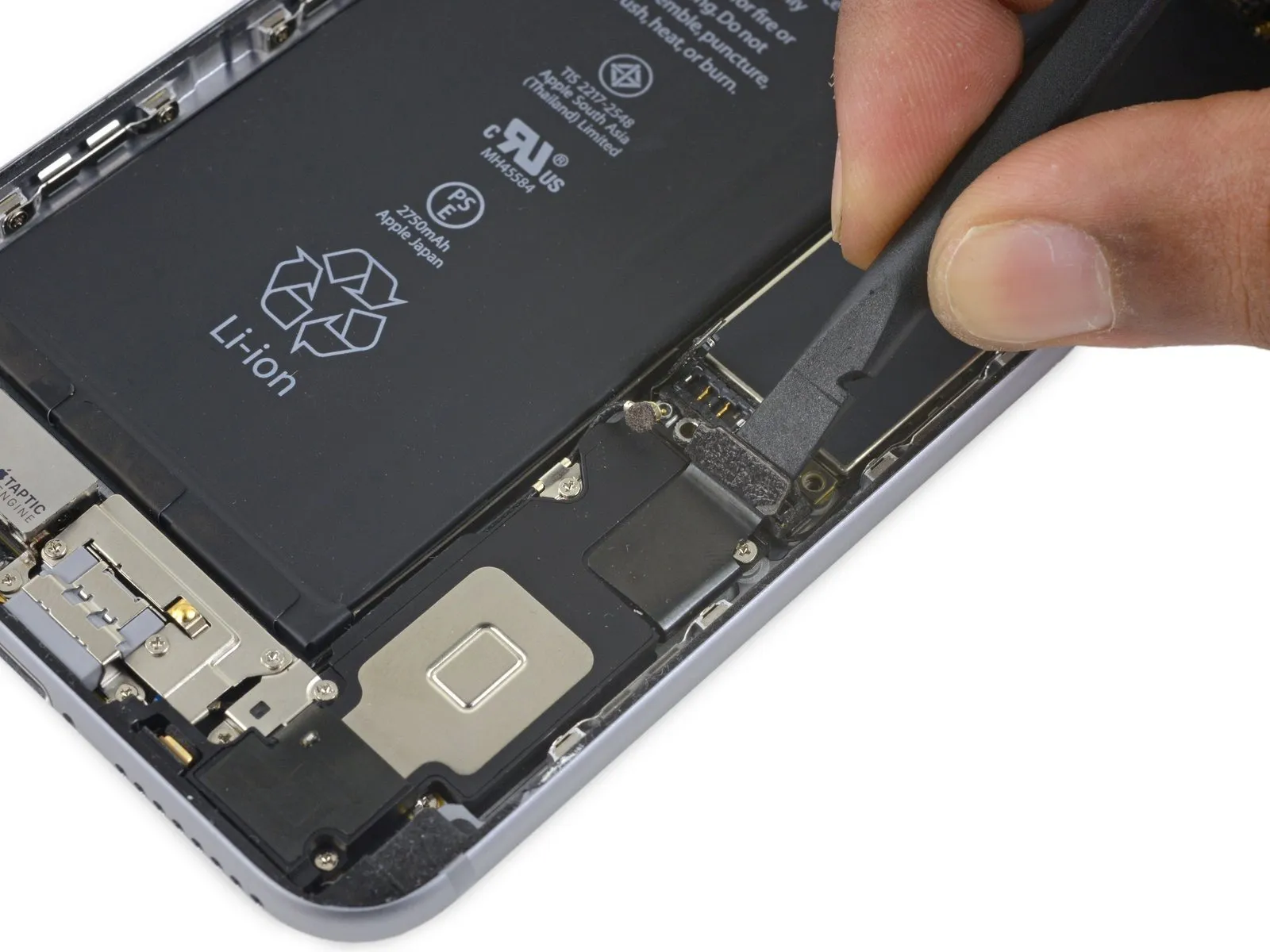
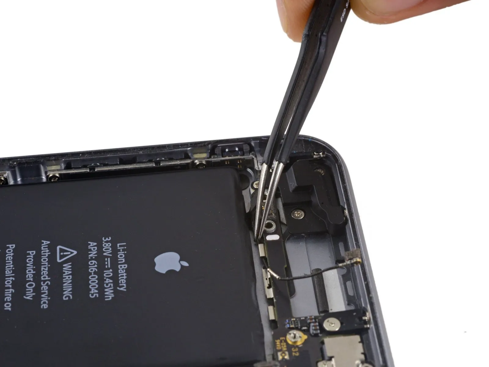
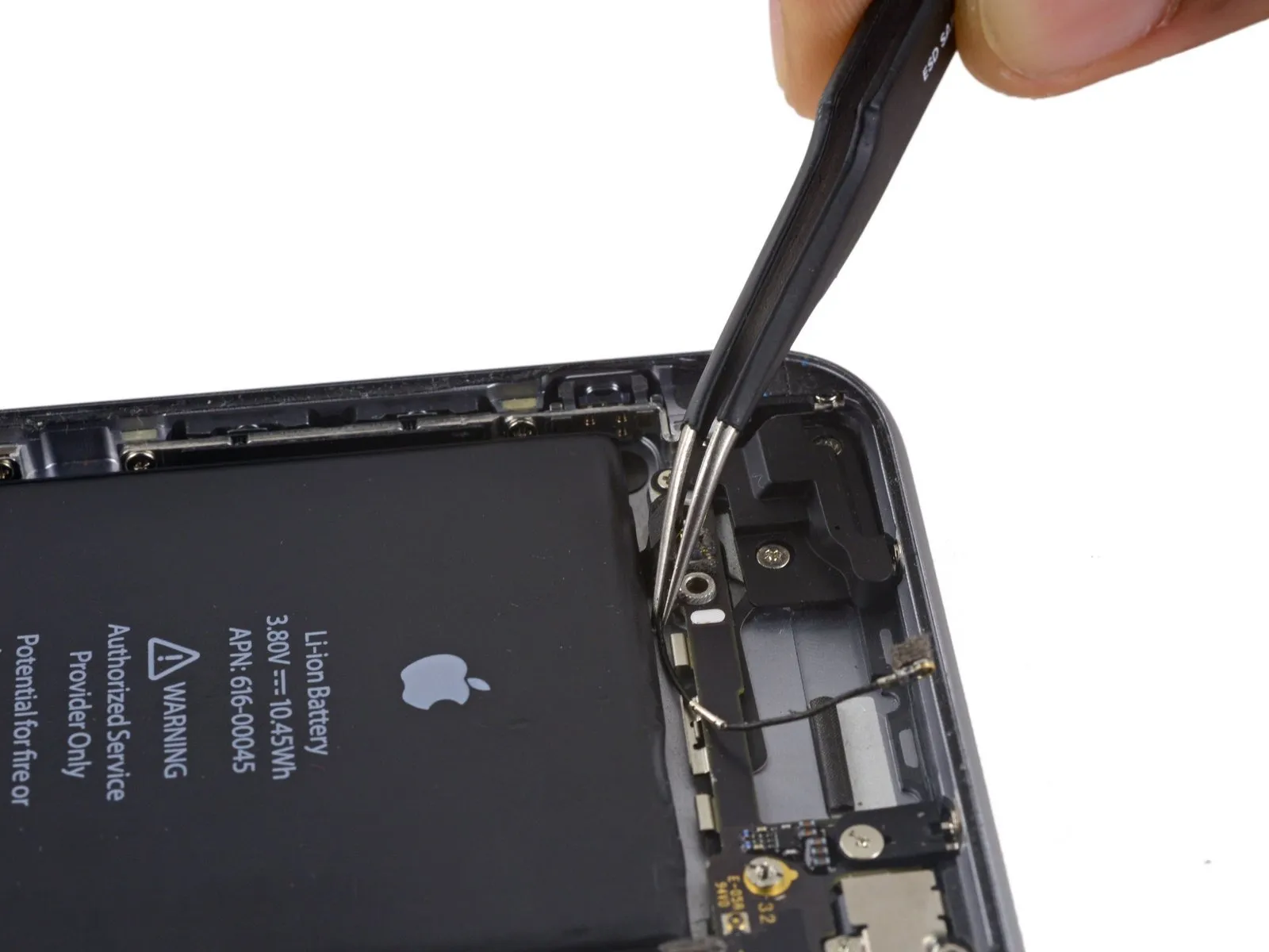
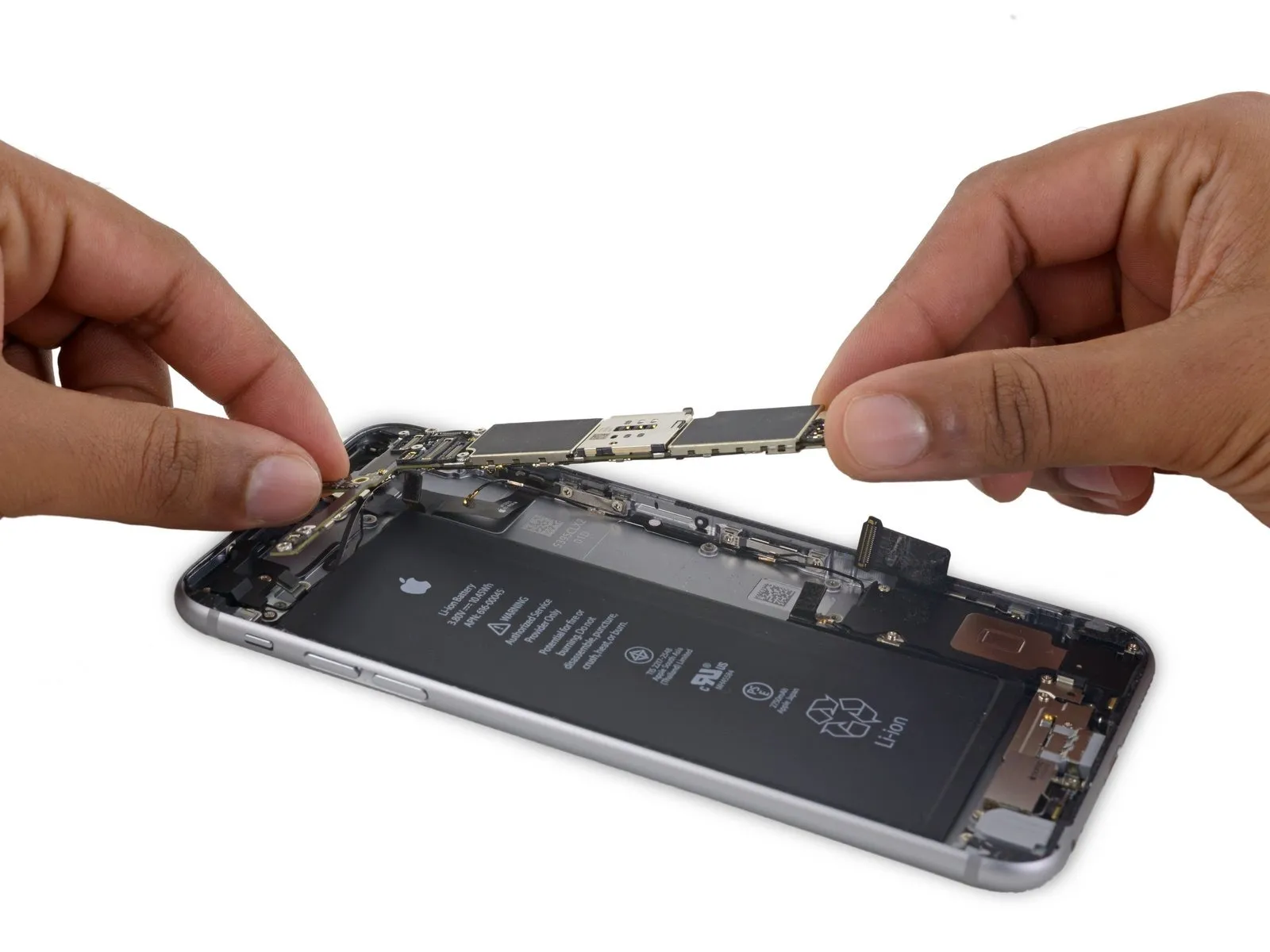
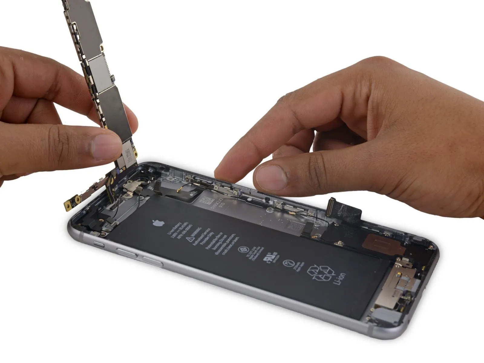
- Position the iPhone so the rear case supports the logic board, ensuring it rests securely with the component side facing upward.
- Carefully separate the Wi-Fi/Bluetooth antenna cable from its connector on the logic board's rear surface, employing the flat spudger tip.
Step 52

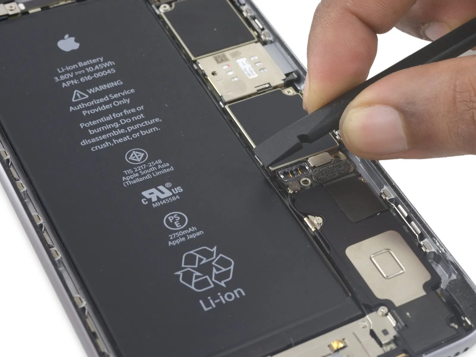
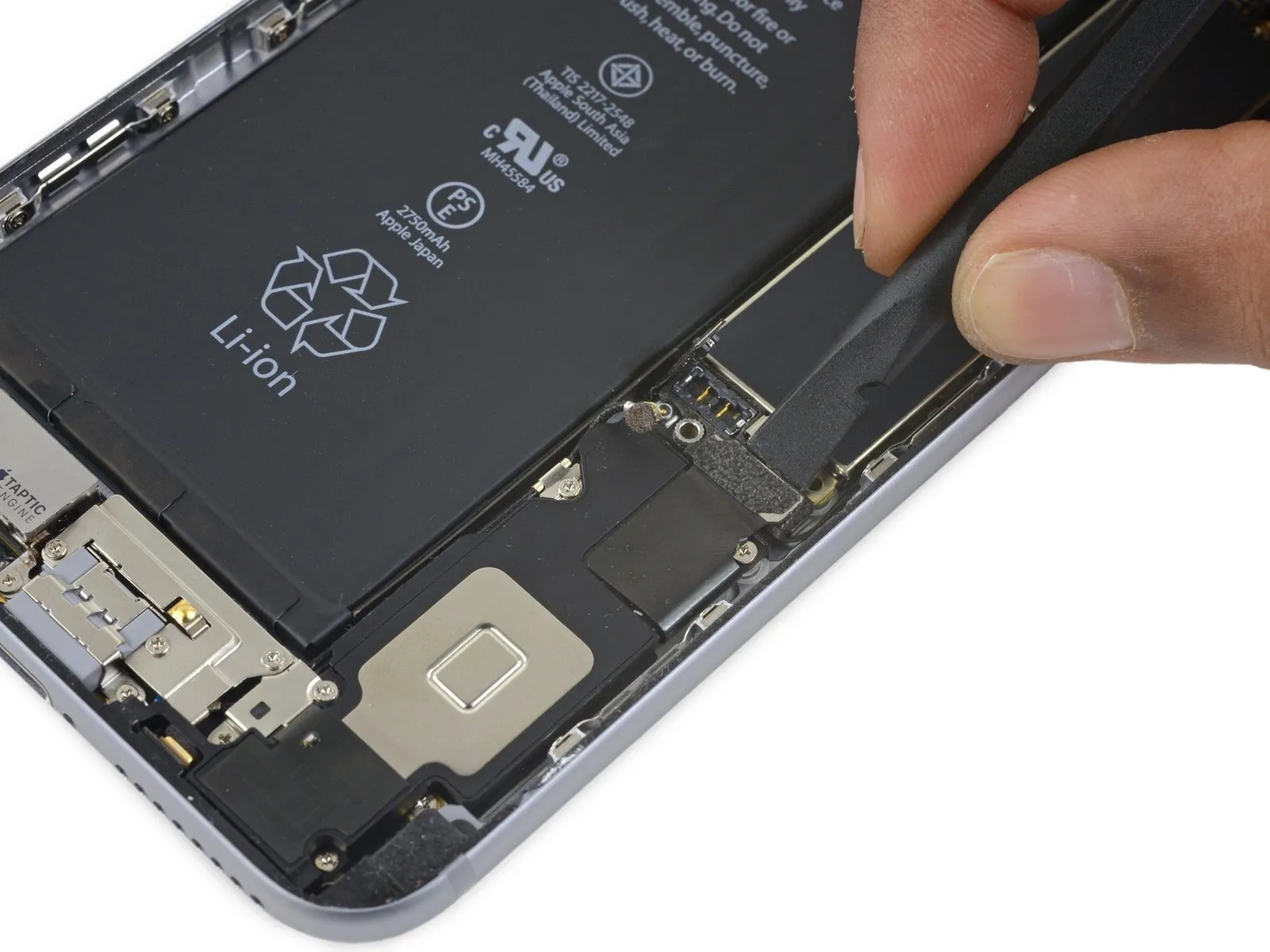
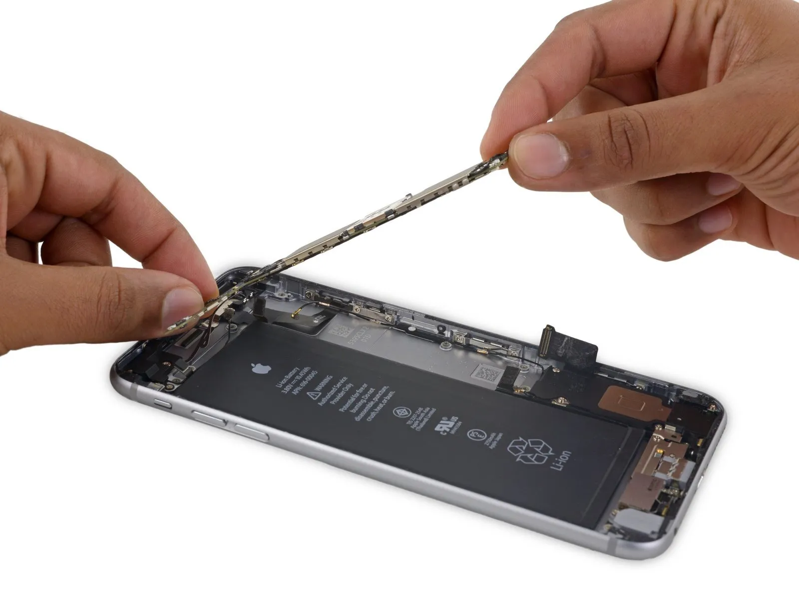
- Carefully detach the logic board from the device, ensuring no components are damaged.
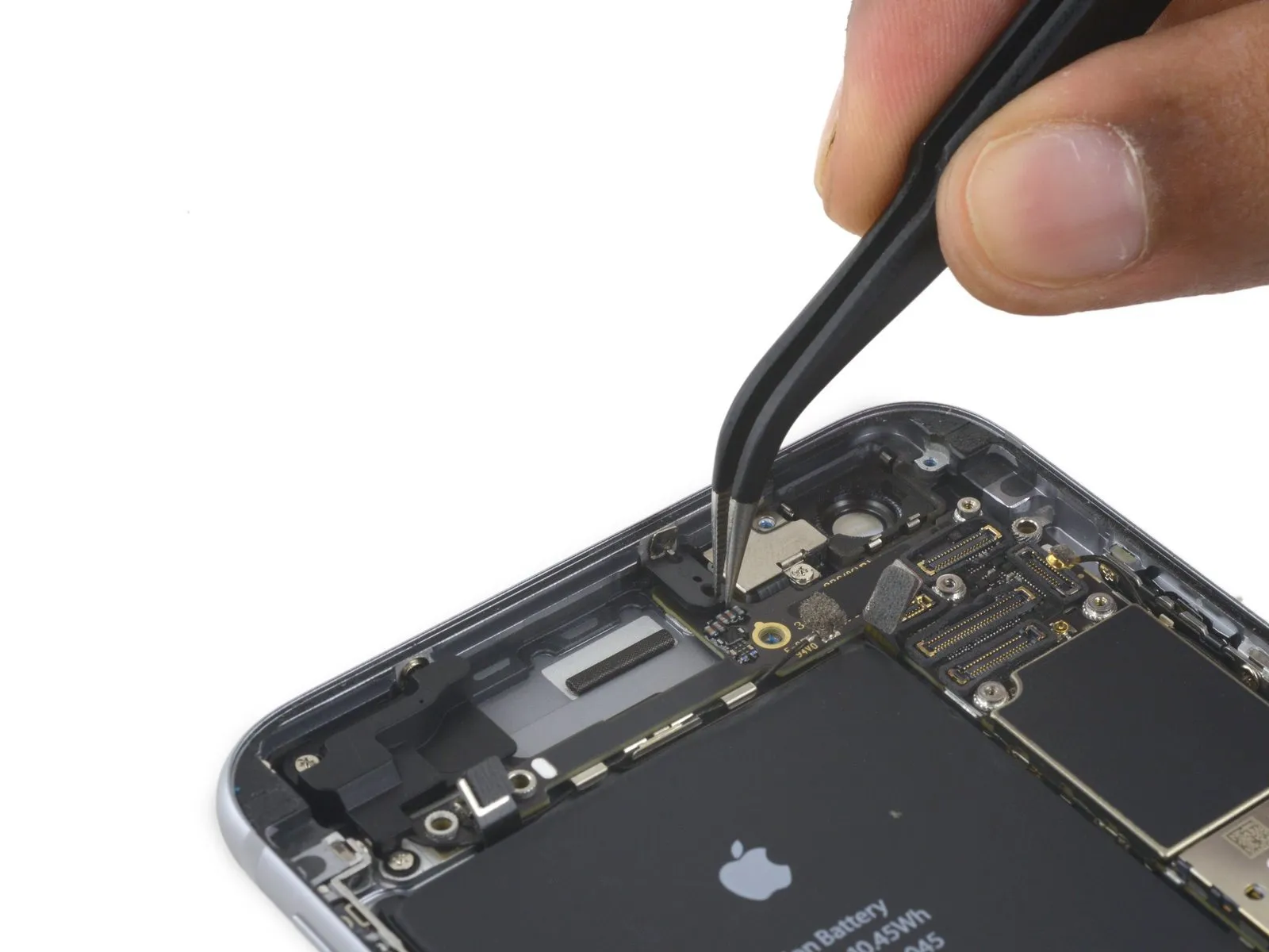
Step 53 | Wi-Fi/Bluetooth Antenna
Step 54

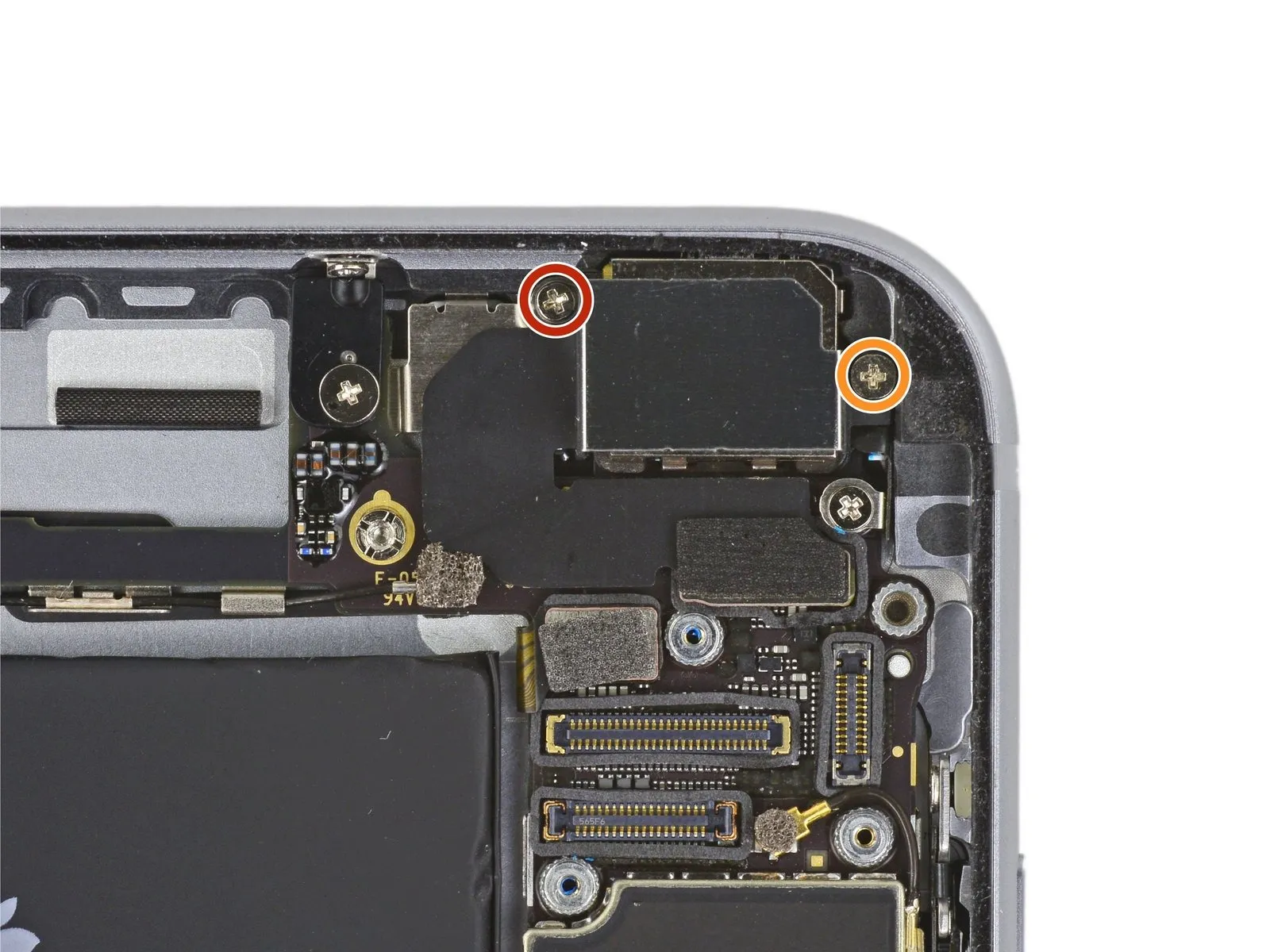
- Using a Phillips screwdriver, detach the cellular antenna by unscrewing the three screws that secure it.
- Begin the process with a single unit.The specified dimension is two point seven millimeters.Fasten with a screw.
- Begin the process with a single unit.One point seven millimeters.Fasten with a screw.
- Begin with a count of one.One point three millimeters.Fasten with a screw.
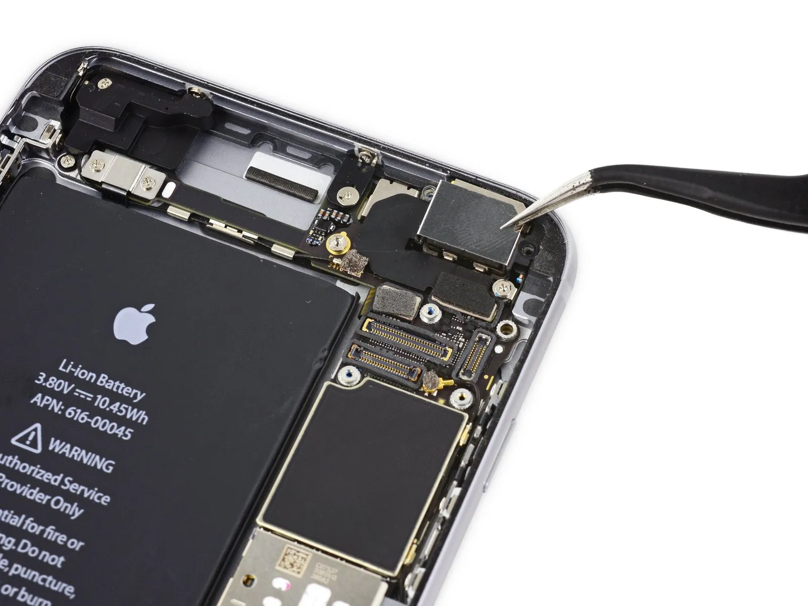
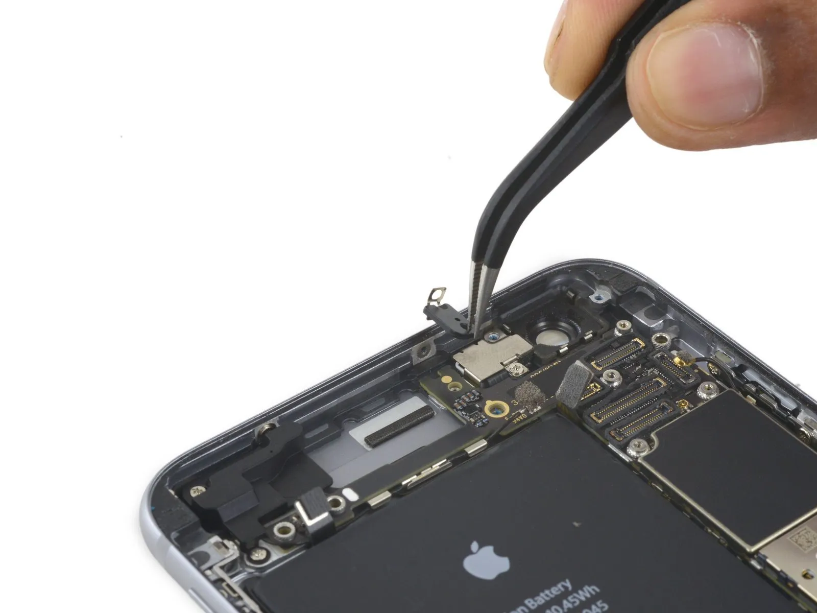
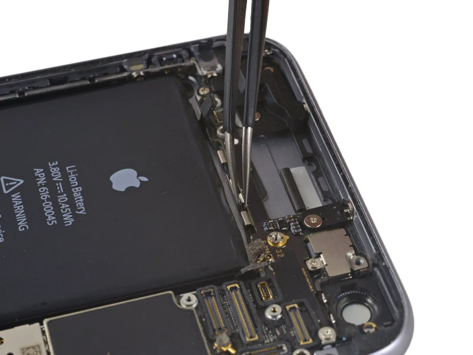
Step 55

Step 56
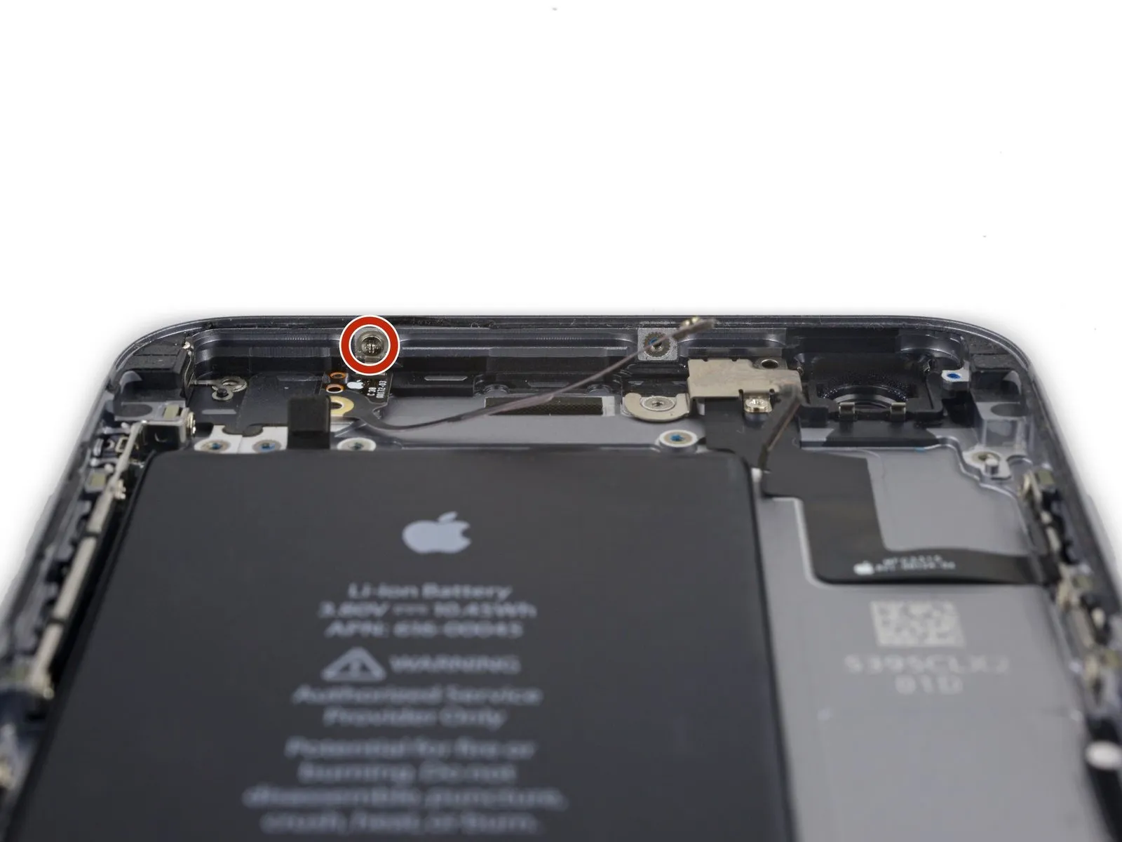
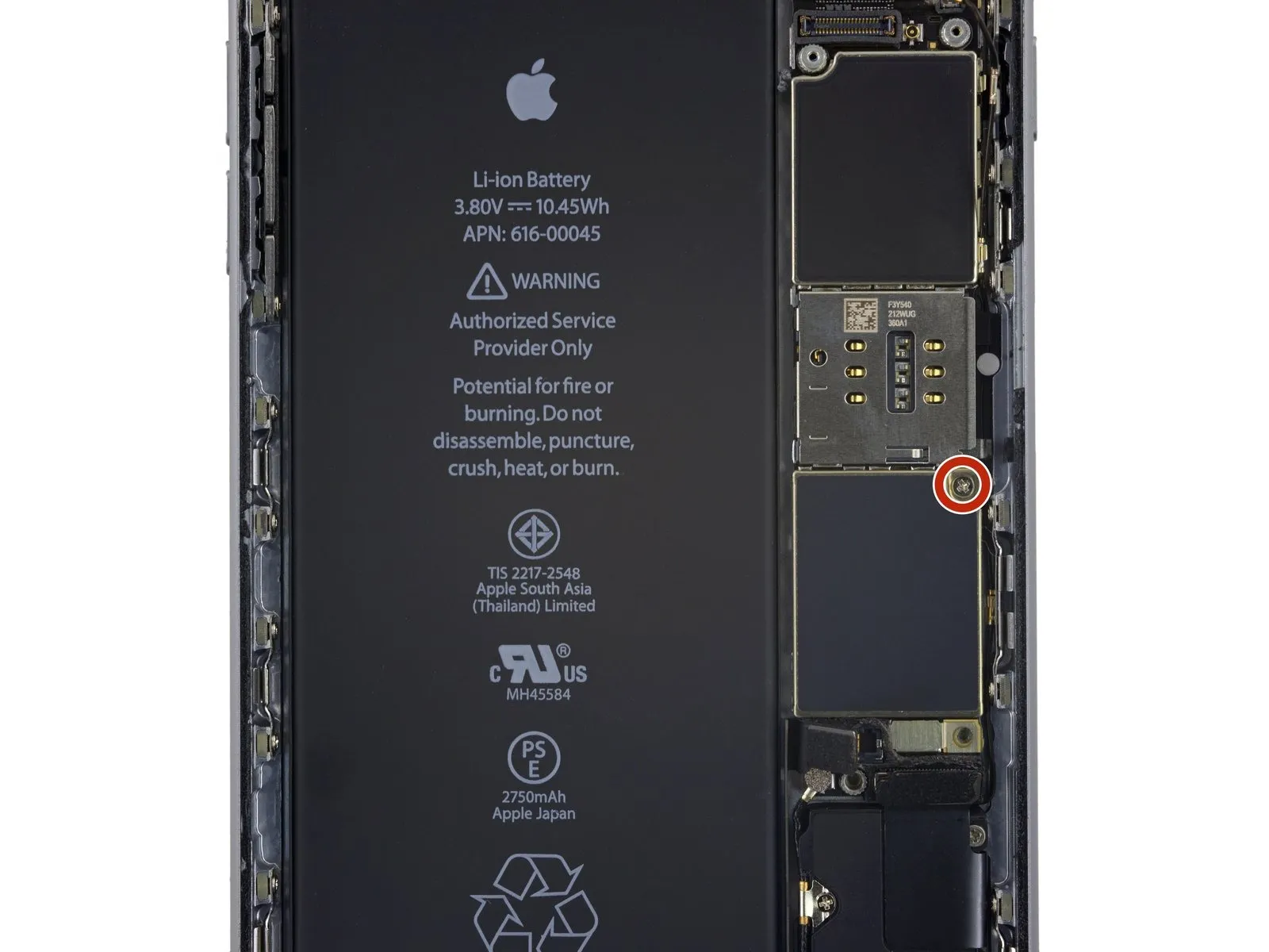
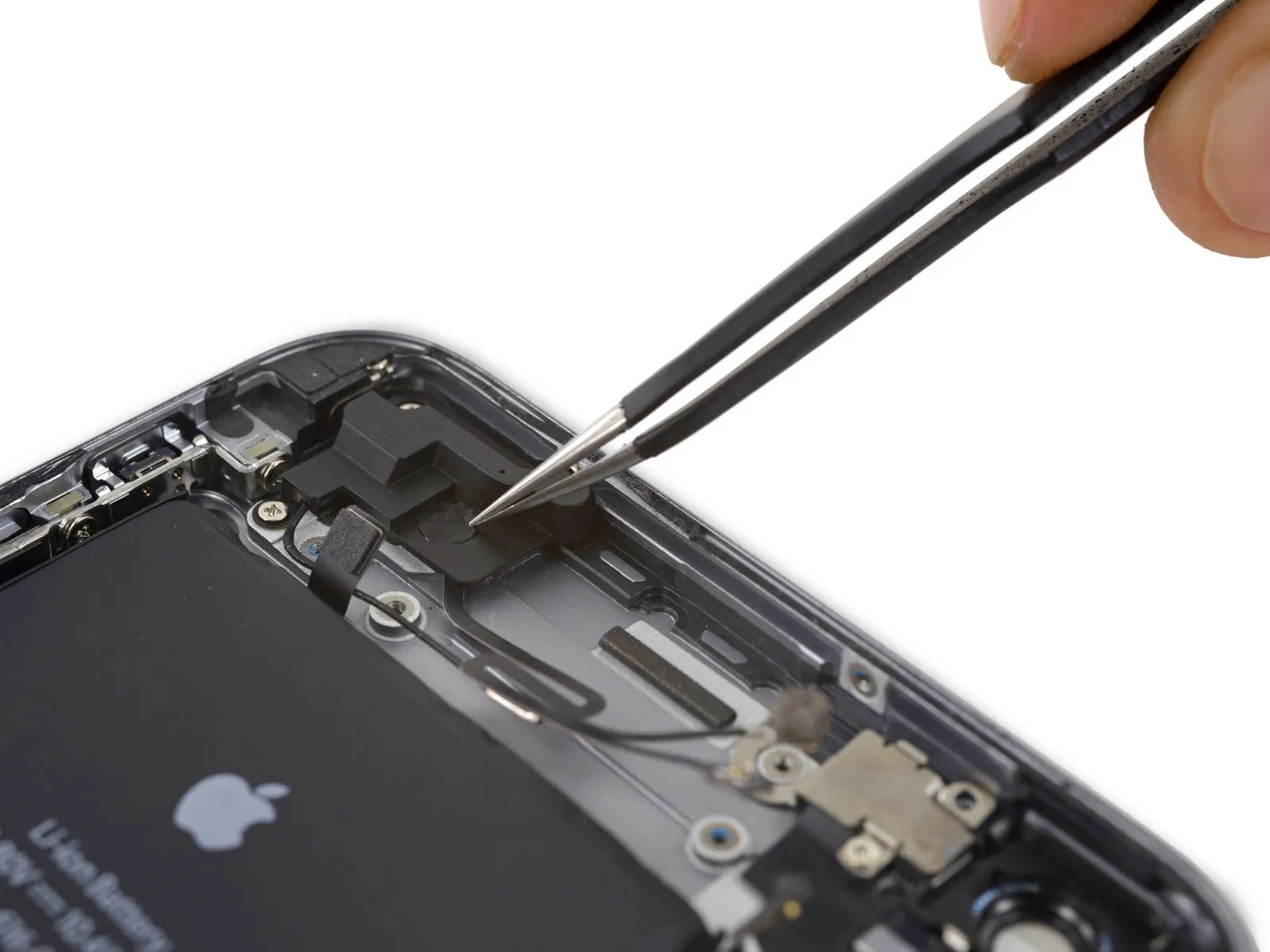
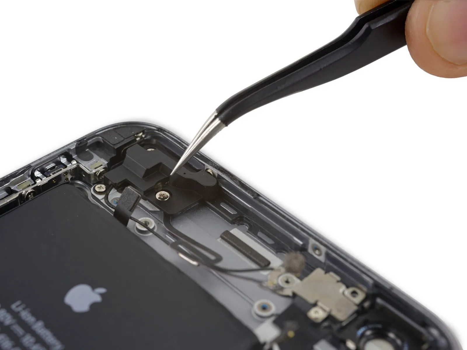
- Detach the solitaryOne point three millimeters.Use a Phillips screwdriver to fasten the antenna to the rear case with the screw provided.
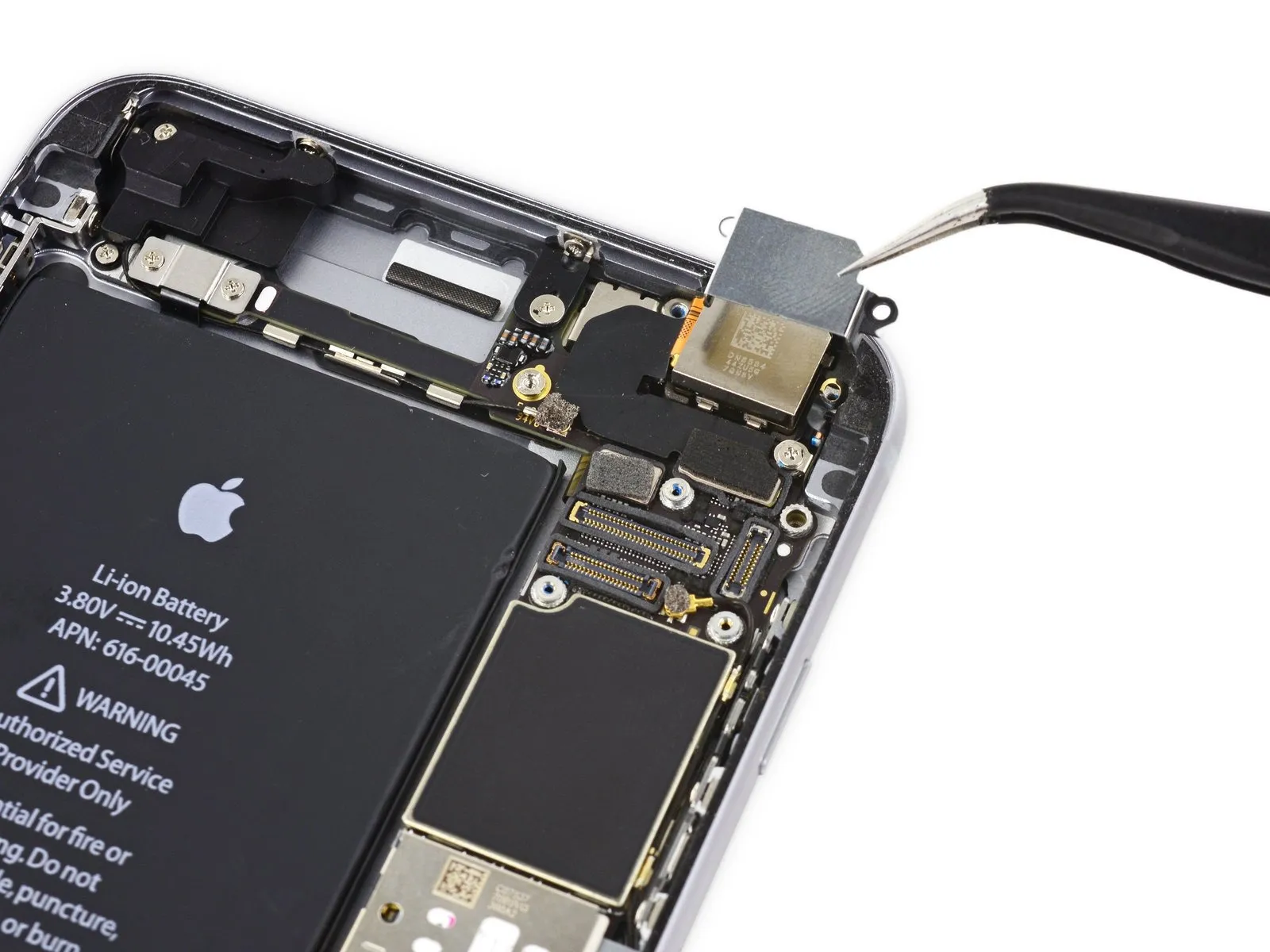
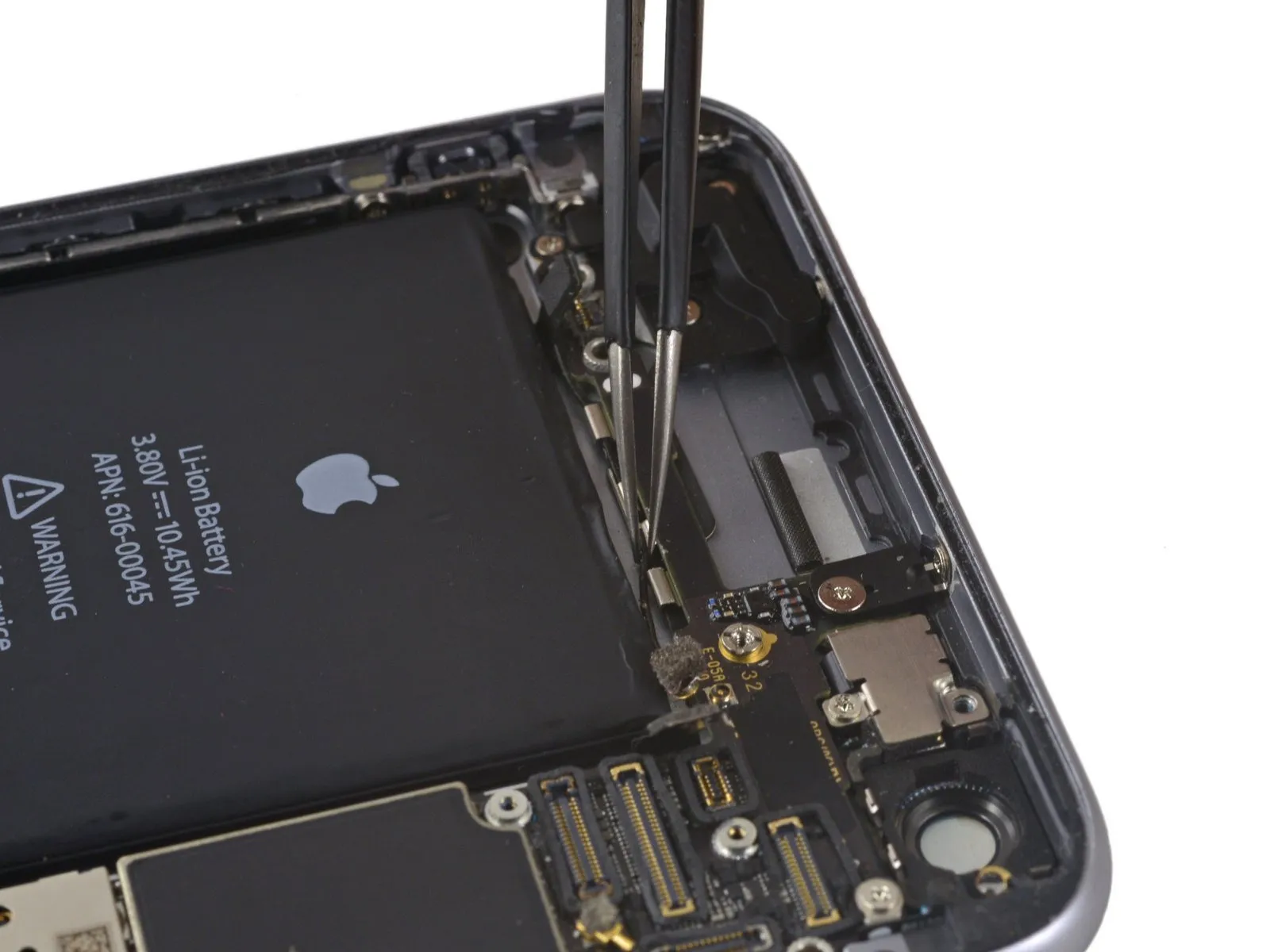
Step 57
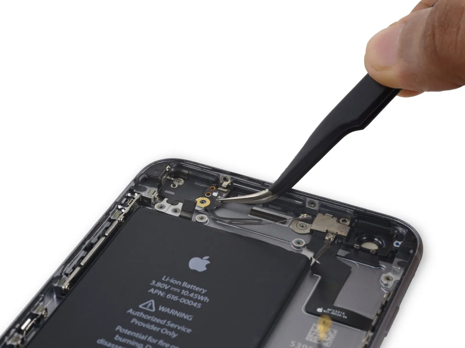
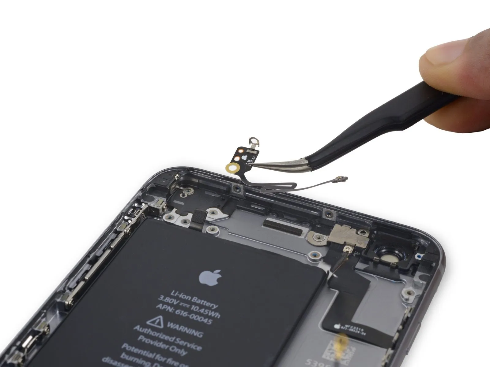
- Carefully detach the Wi-Fi/Bluetooth antenna, ensuring no damage occurs.