iPhone 6s Plus Rear Case Replacement
Employ this instruction manual to substitute a warped or broken rear housing, or to exchange it purely for aesthetic enhancements. Given that the rear case functions as the foundational structure of the entire device, its replacement necessitates the disassembly of every internal component within the iPhone.
- Furthermore, this guide can be utilized to substitute these additional parts:
Step 1 | Pentalobe Screws
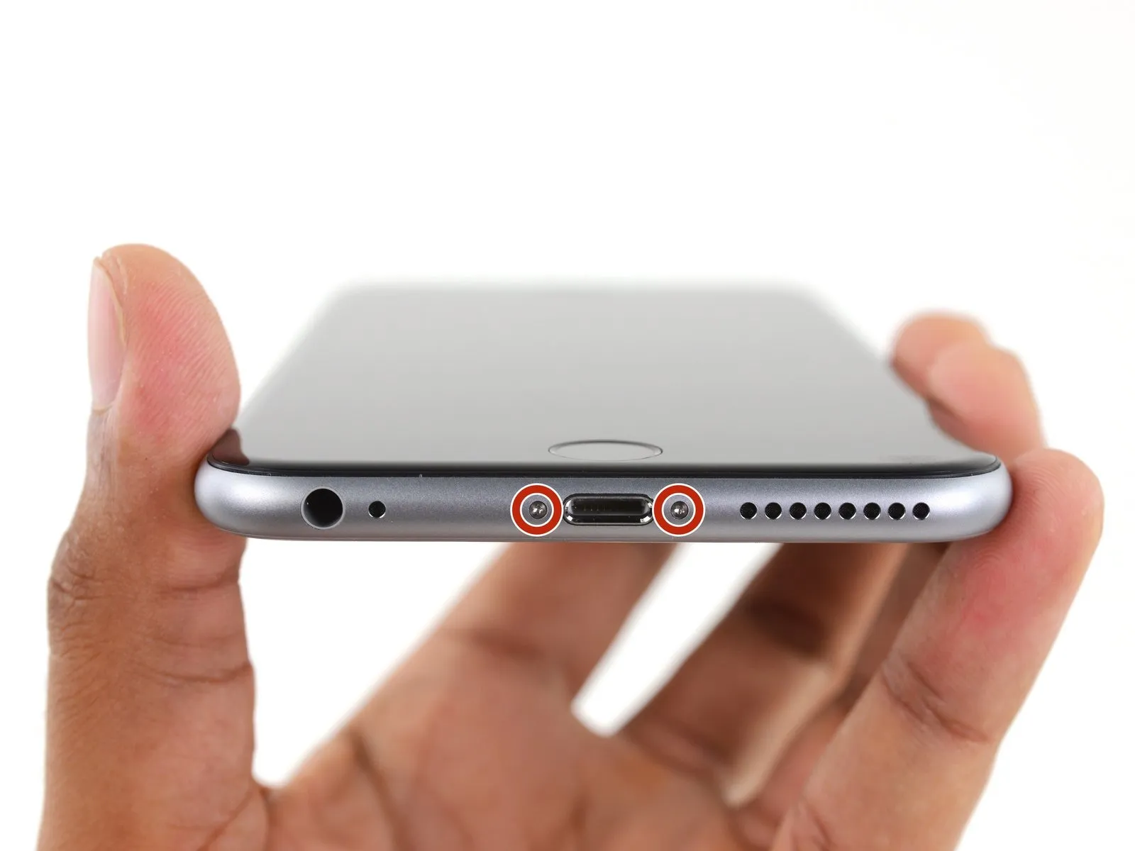
- Ensure the battery's charge level is less than 25%; a fully charged lithium-ion battery presents a fire hazard and potential explosion risk if it sustains damage.
- Deactivate your iPhone by powering it down to prevent any electrical issues during the disassembly process.
- Begin by unscrewing the pair of 3.4 mm Pentalobe screws located on both sides of the Lightning connector.
Step 2 | Anti-Clamp instructions


- Should you choose not to utilize the Anti-Clamp, proceed to skip ahead three steps to access an alternative approach.
- Detailed instructions regarding the Anti-Clamp's operation can be found within this separate guide.
- To release the Anti-Clamp's gripping arms, retract the blue handle towards the rear.
- Carefully position the arms across either the left or right side of your iPhone’s frame.
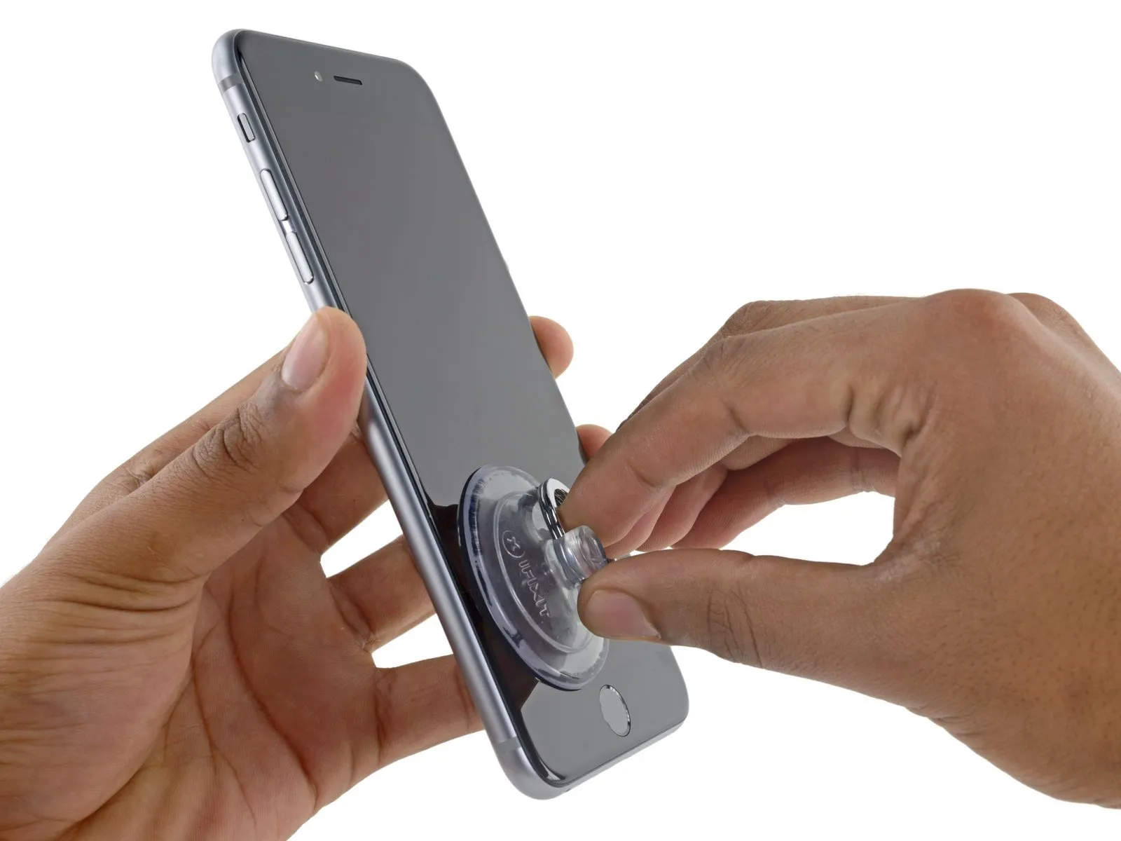
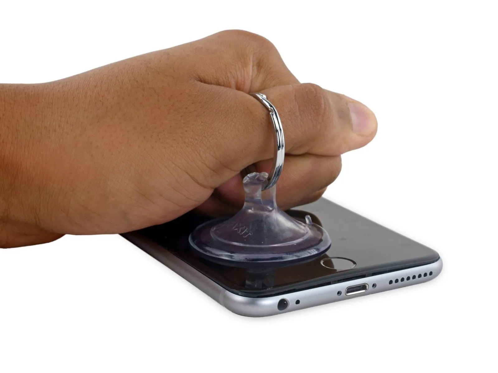
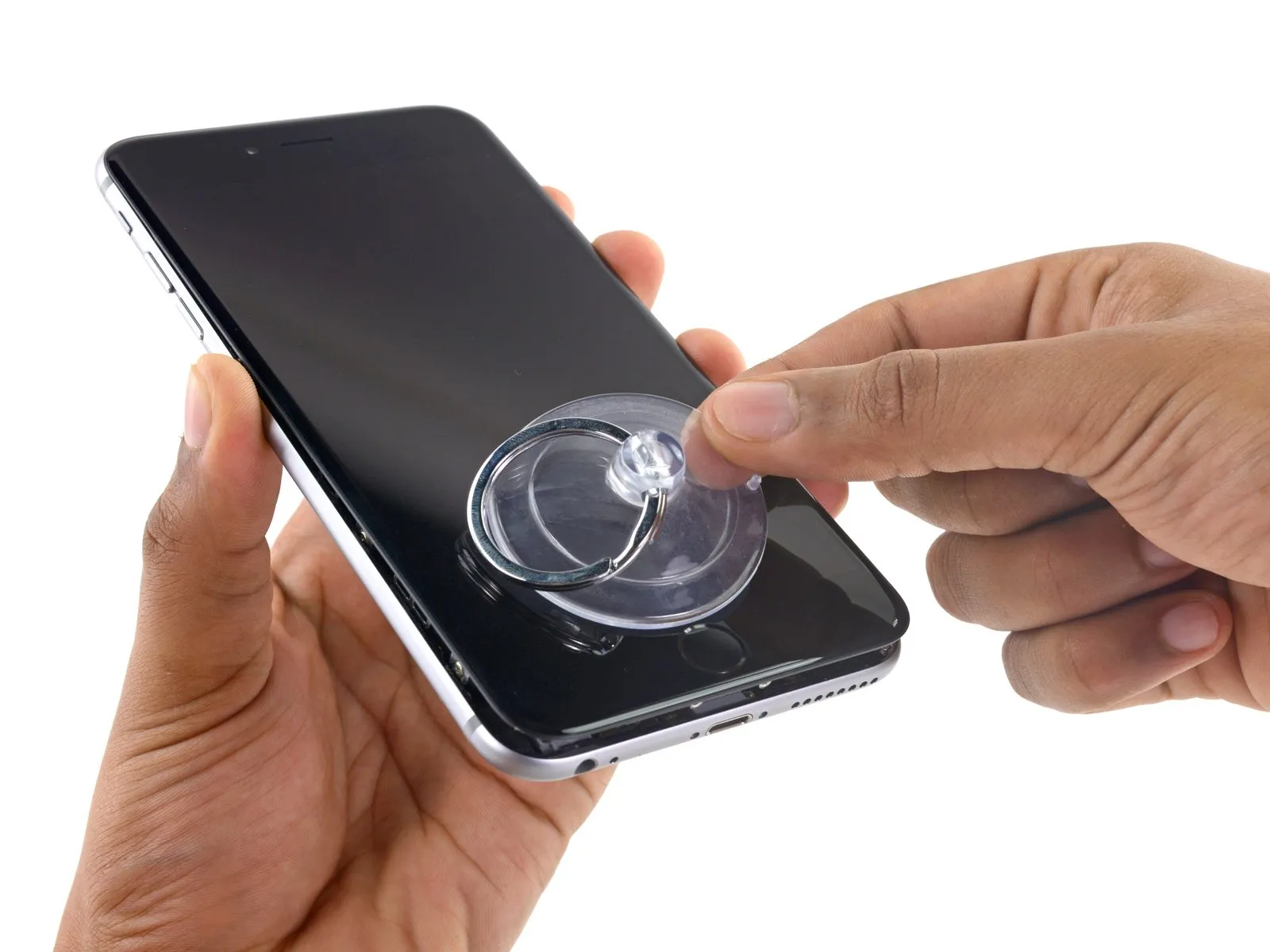
- Place the suction cups close to the lower edge of the iPhone, situated directly above the home button; one cup should be on the front surface, and the other on the rear.
- Apply pressure by compressing the cups together to establish a secure suction bond to the intended area.
- In cases where the iPhone’s surface exhibits excessive slipperiness, hindering the Anti-Clamp’s ability to maintain grip, applying adhesive tape can provide a more textured surface.
Step 3


- Rotate the handle a full 360 degrees, or continue turning until the suction cups begin to expand.
- Maintain the precise alignment of the suction cups; should they become misaligned, slightly release the suction cups and readjust the arms.
Step 4 | Opening Procedure
- Introduce gentle warmth to the iPhone's bottom border with either an iOpener or a hair dryer, maintaining the heat for approximately one minute.
- The application of heat serves to reduce the stiffness of the adhesive that holds the display in place, thereby simplifying the opening process.
Step 5
- Should you wish to substitute the existing adhesive, ensure a fresh supply of adhesive strips is accessible prior to proceeding. The repair can be successfully finished without adhesive replacement, and operational performance is unlikely to be affected.
In situations where the display exhibits severe cracking, applying a transparent layer of packing tape can improve the suction cup's grip. As an alternative, a robust adhesive tape can be utilized in place of the suction cup. If adhesion remains problematic, a small amount of superglue can be used to attach the suction cup to the fractured screen.
Step 6
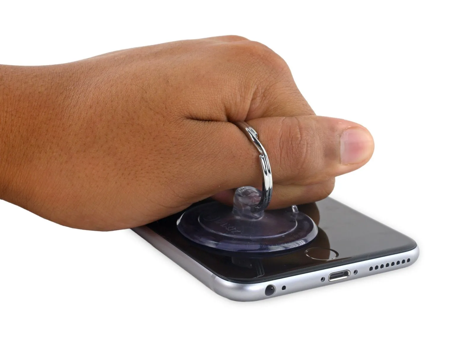
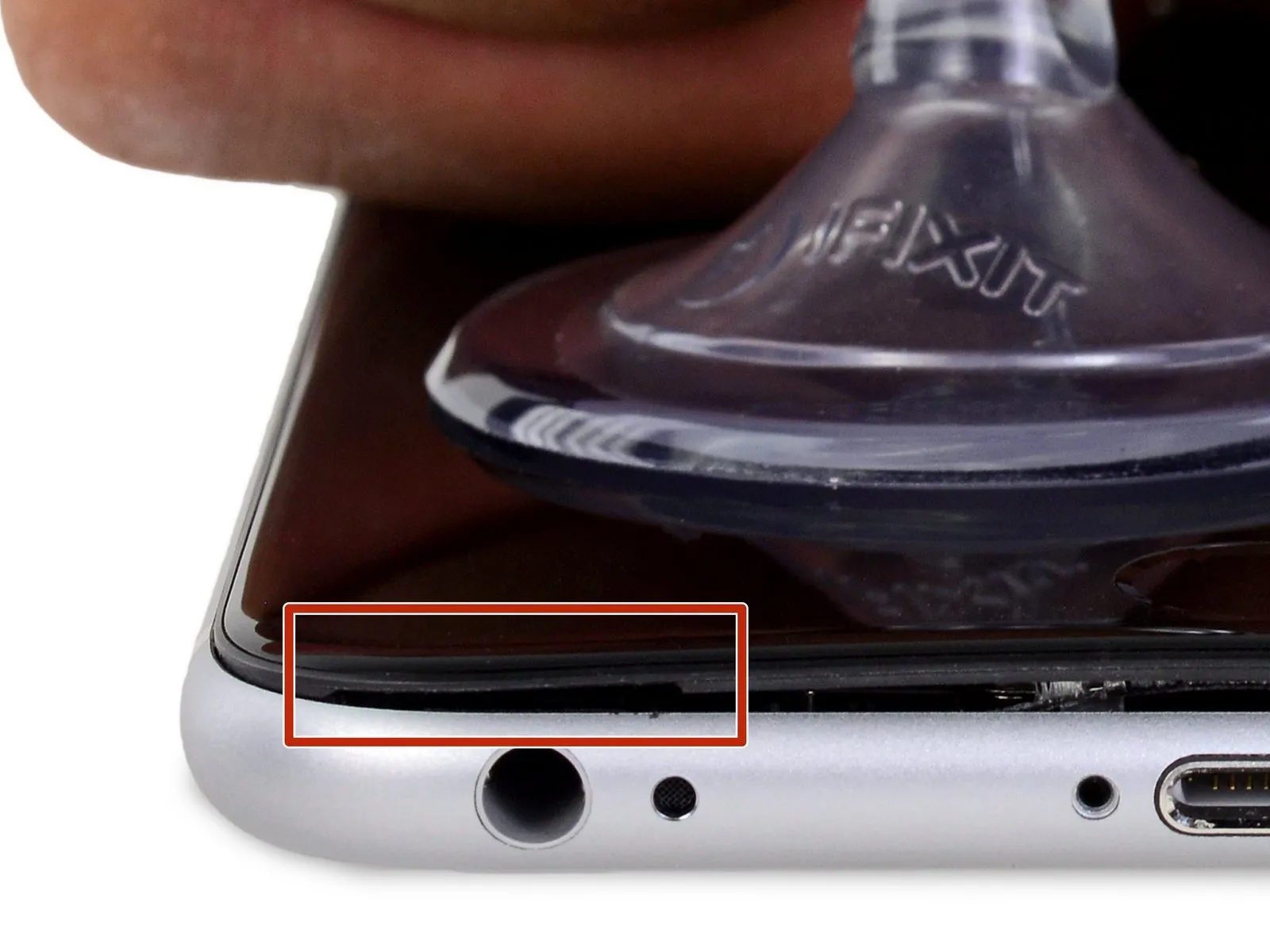
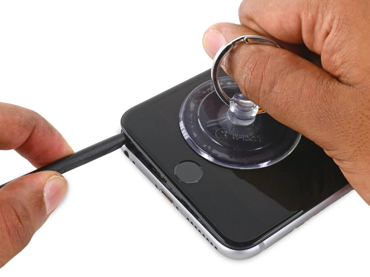
- To separate the front panel from the rear case, exert steady, consistent upward force on the suction cup, ensuring a minimal space forms.
Step 7

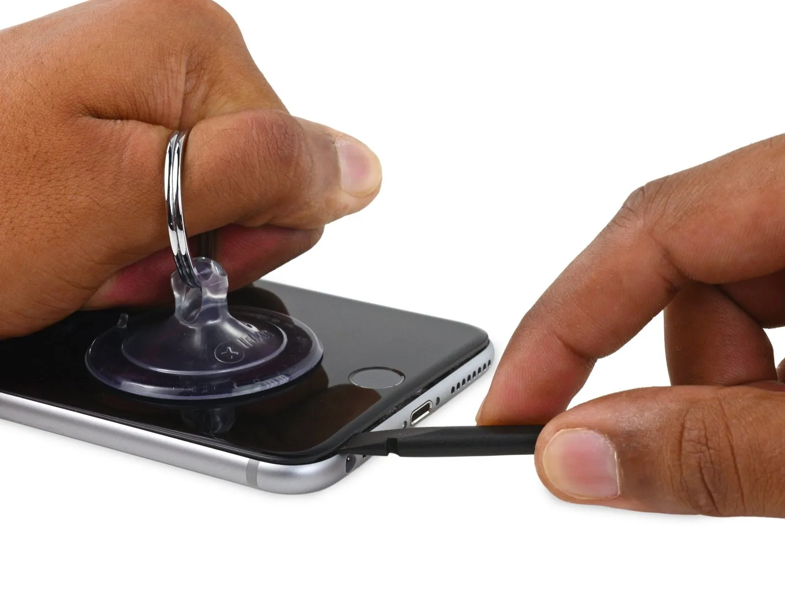
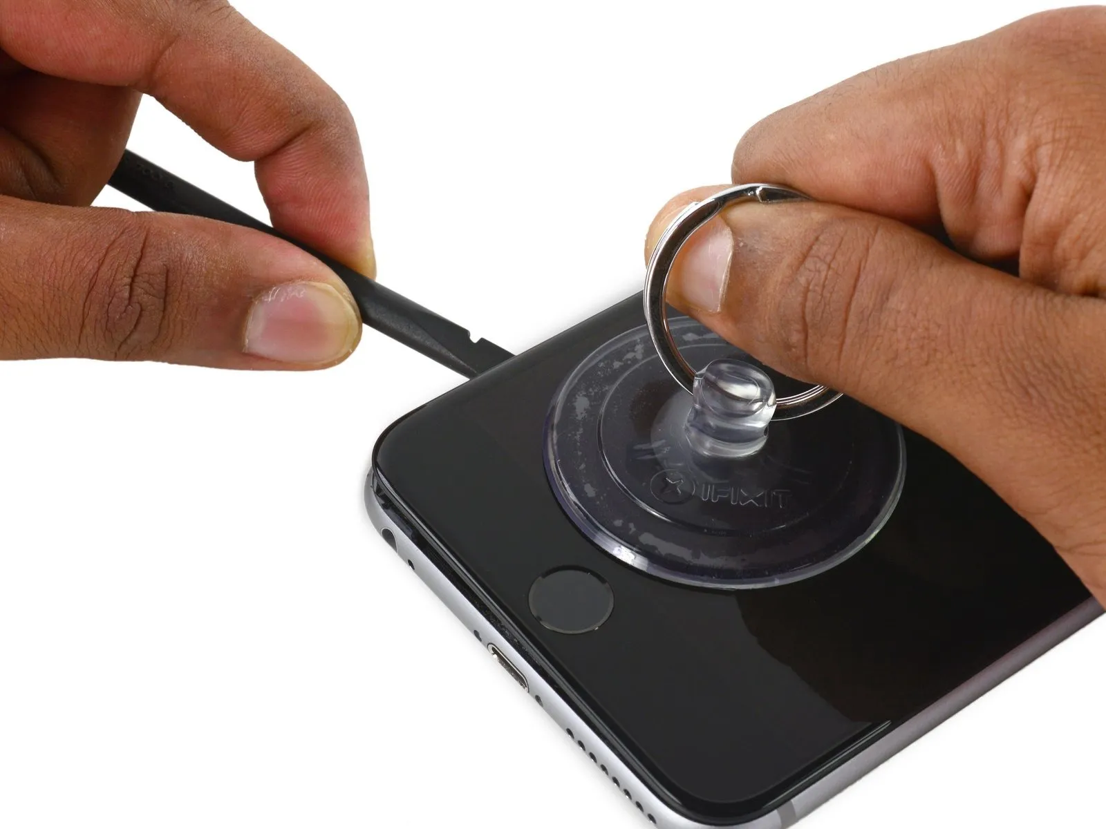
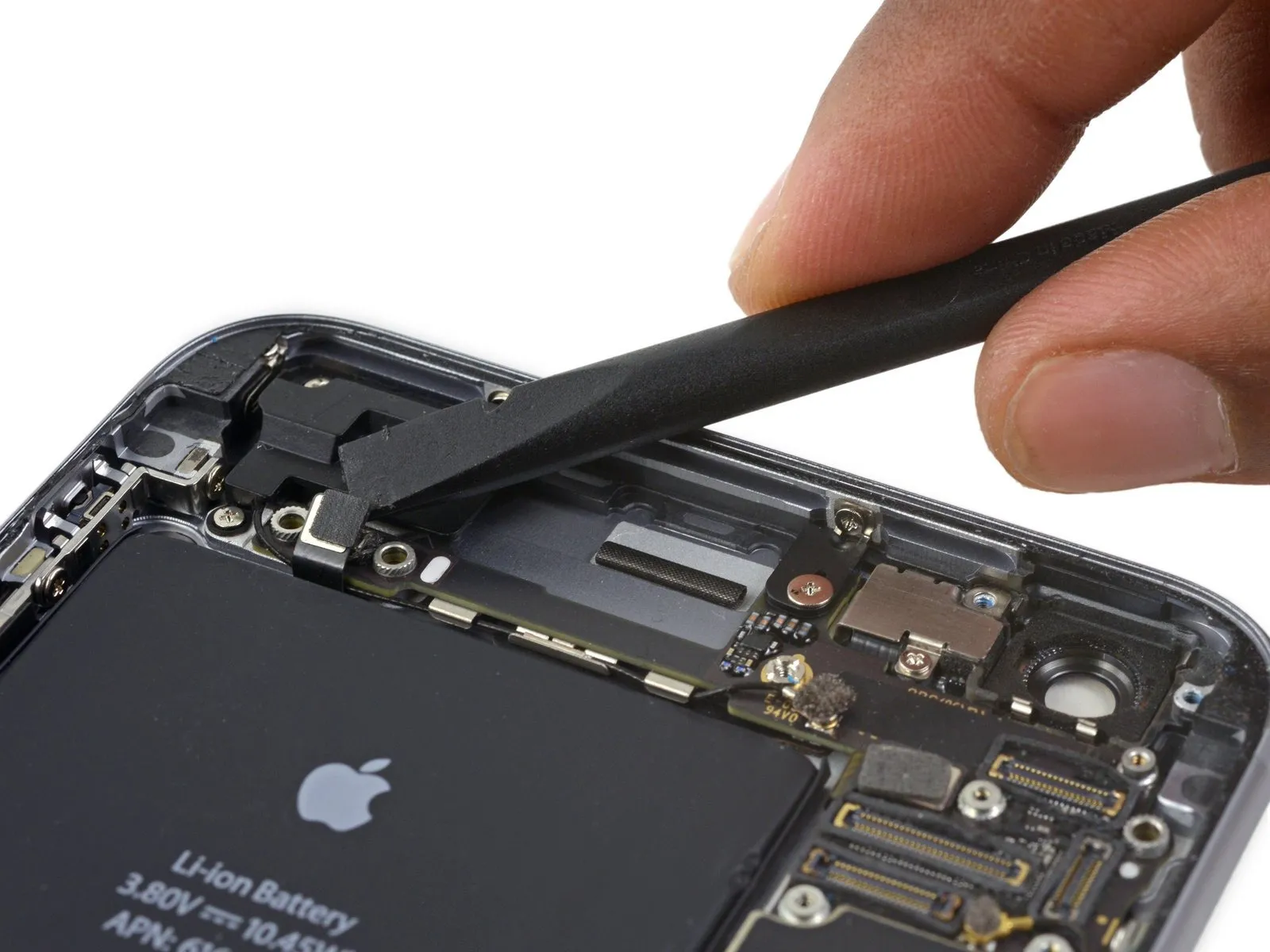
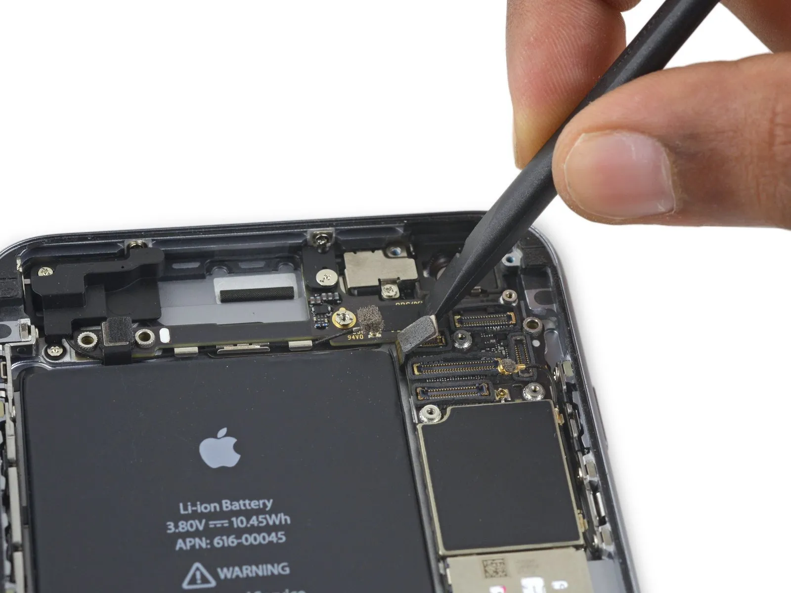
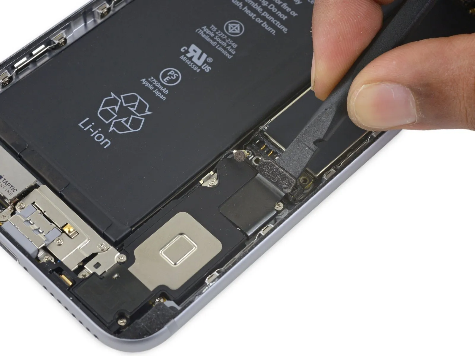
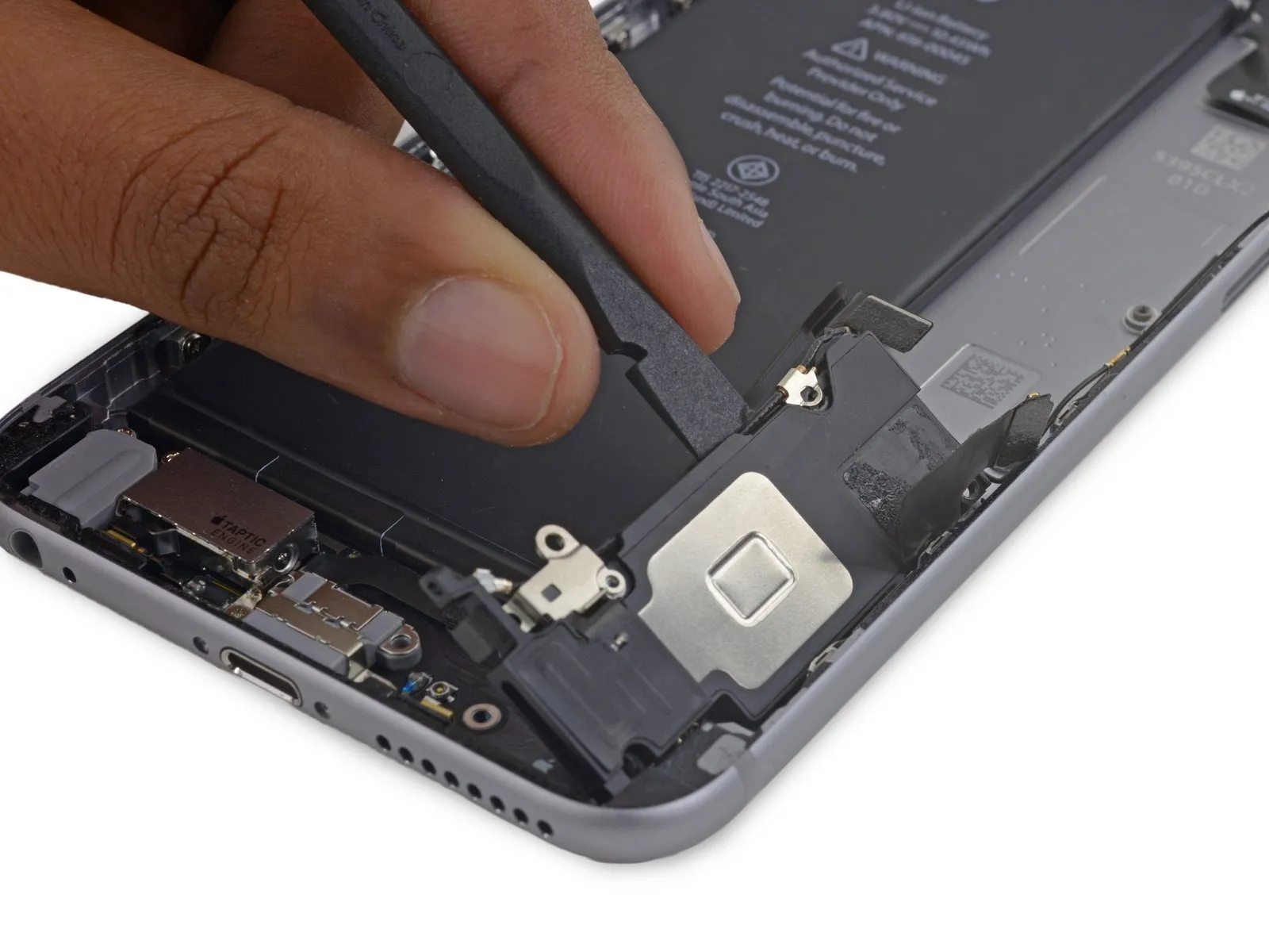
Continuing to apply consistent downward force with the suction cup, carefully slide the thin, wedge-shaped end of a spudger into the newly formed space, precisely located above the headphone jack.
Step 8
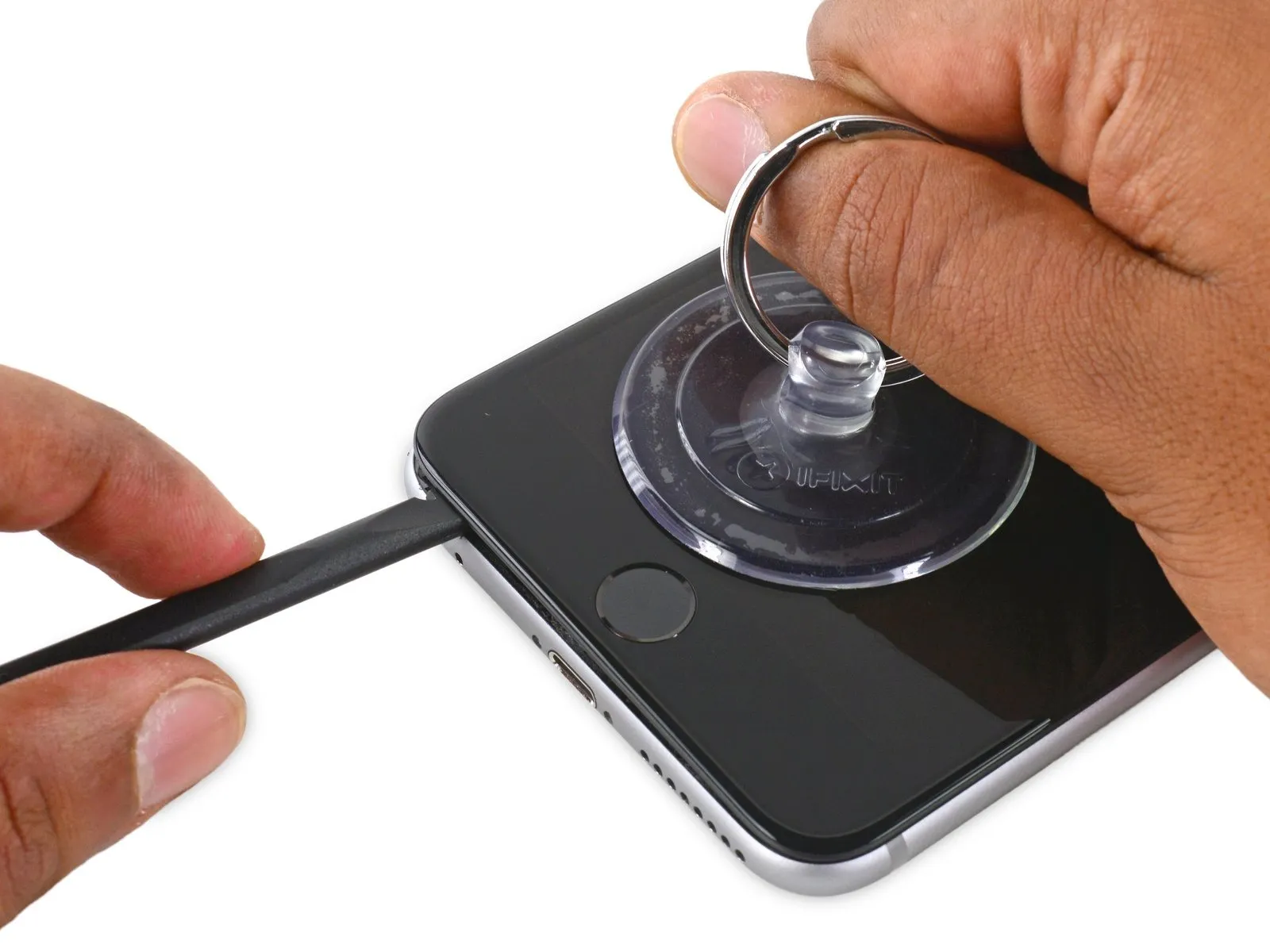
- Utilize the spudger, rotating it to incrementally increase the separation between the front panel assembly and the rear enclosure.
Step 9


Step 10
Step 11


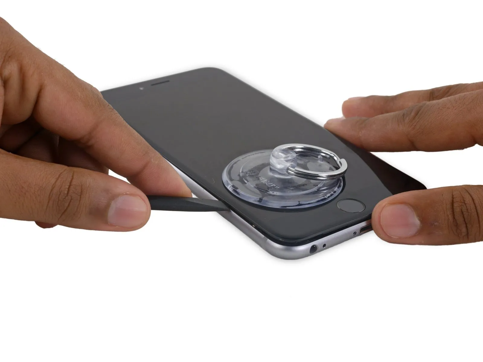
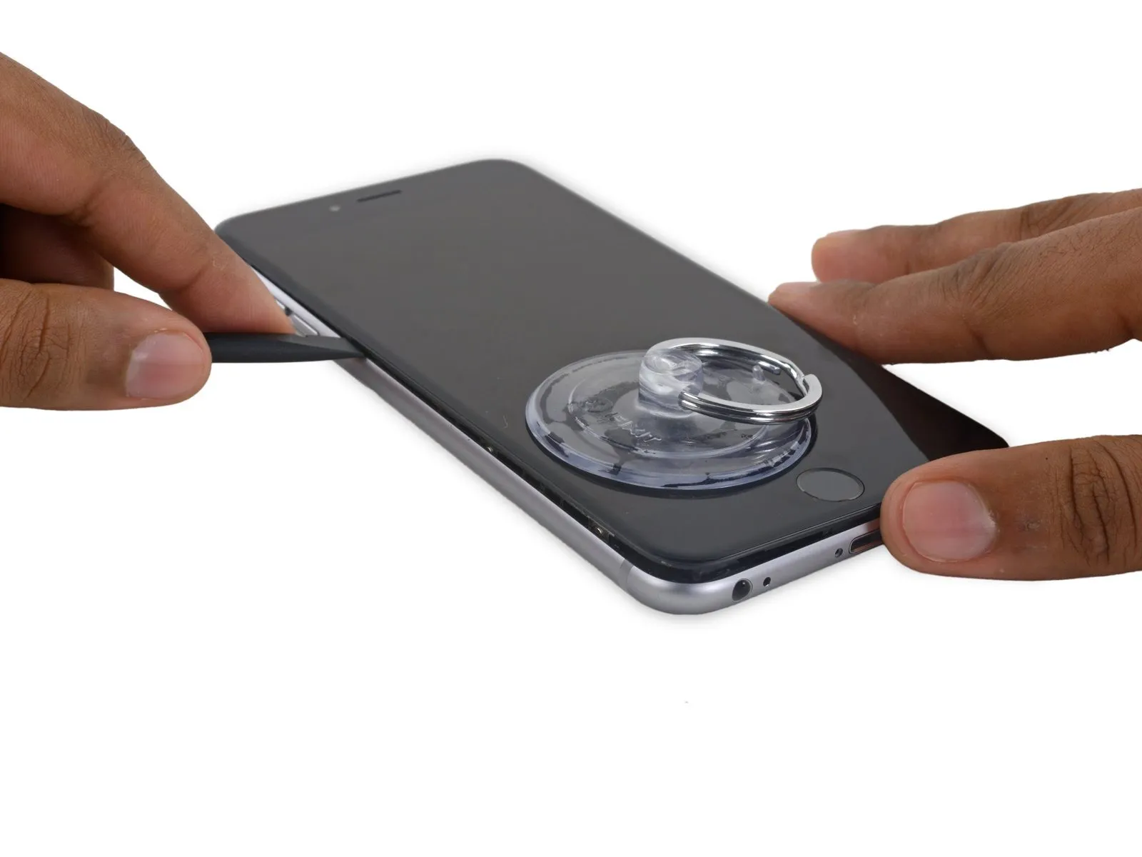
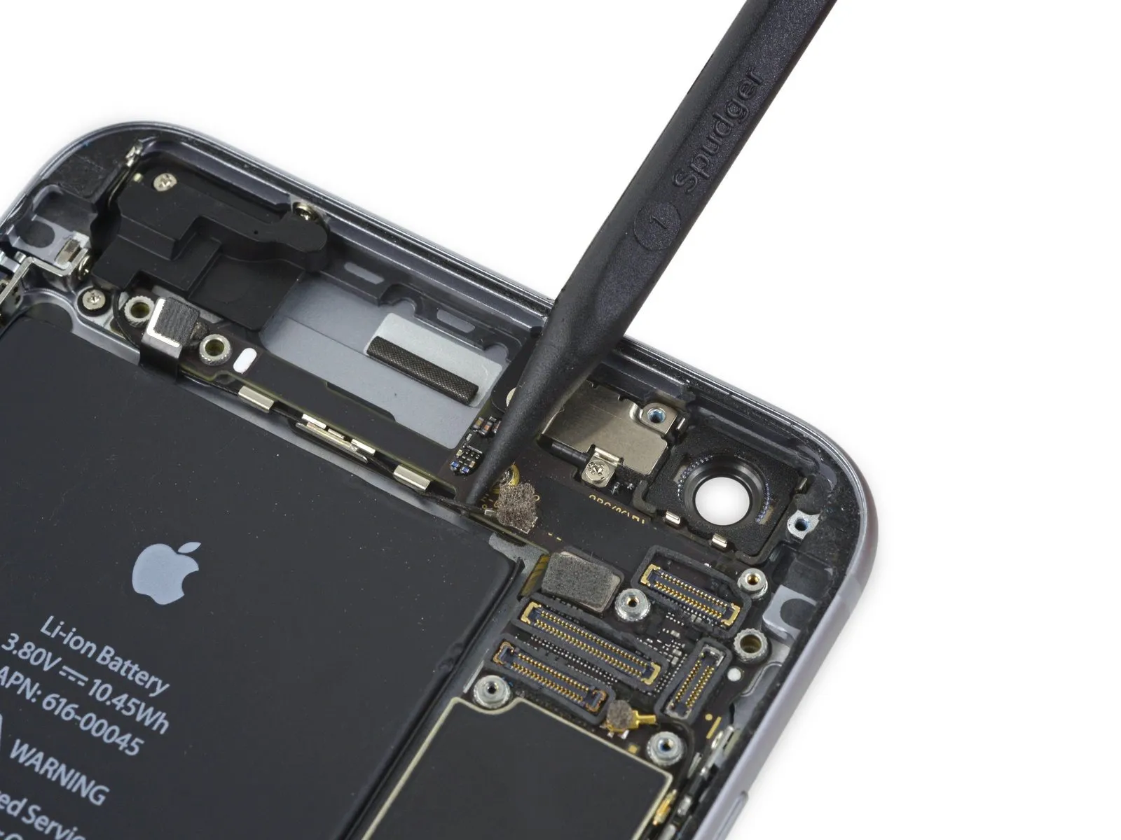
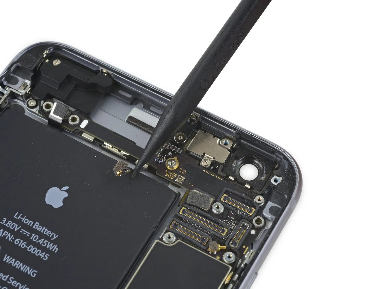
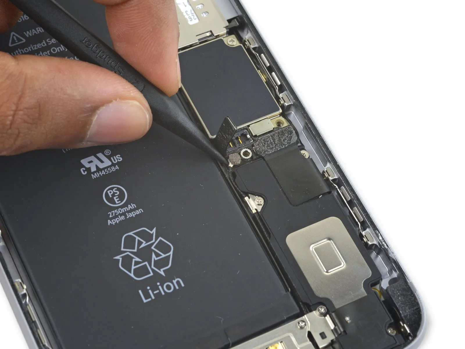
- Employing the flat end of the spudger, carefully position it beneath the rightmost border of the display.spudgerTo separate the display from the device's frame, gently maneuver the spudger beneath the right edge.
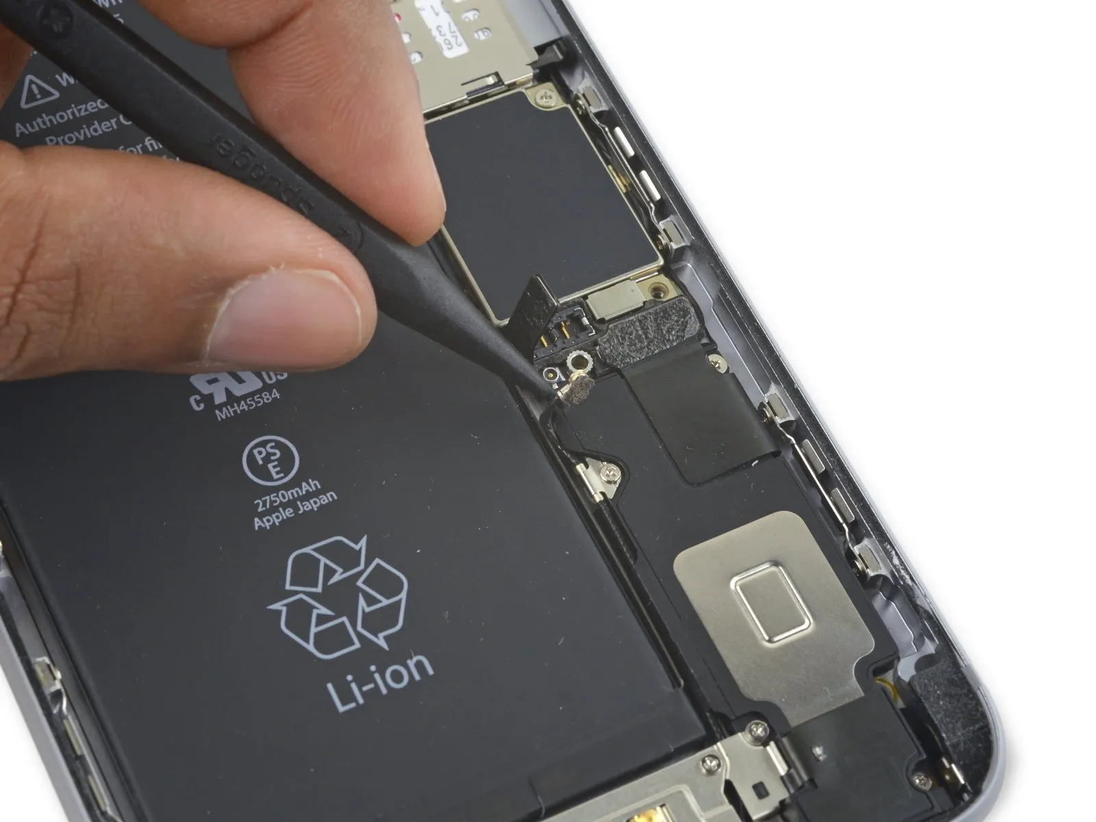
- Using the spudger, proceed to slidespudgeralong the right-hand side of the device.
Step 12


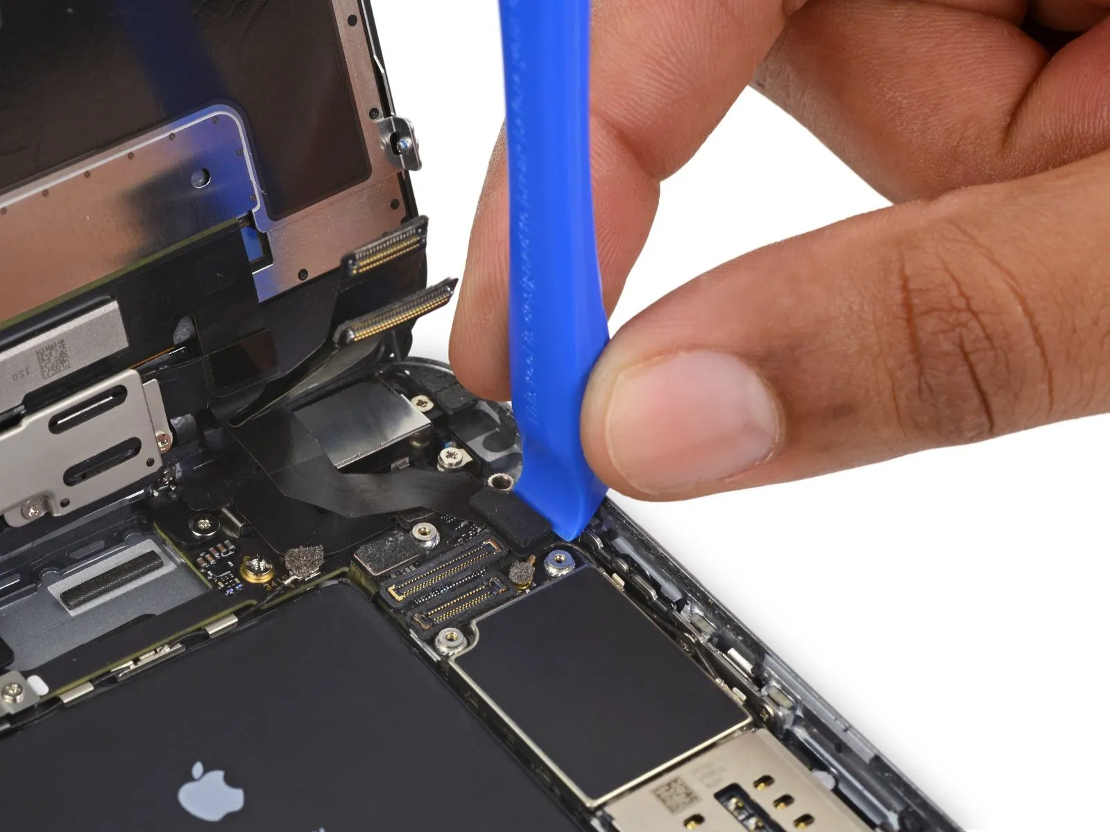
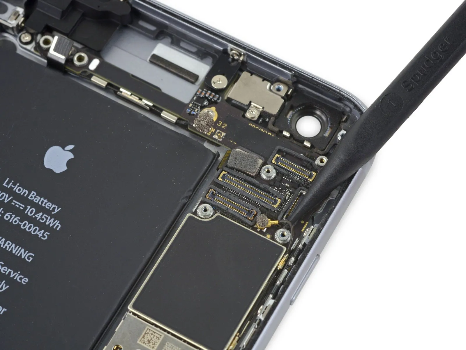
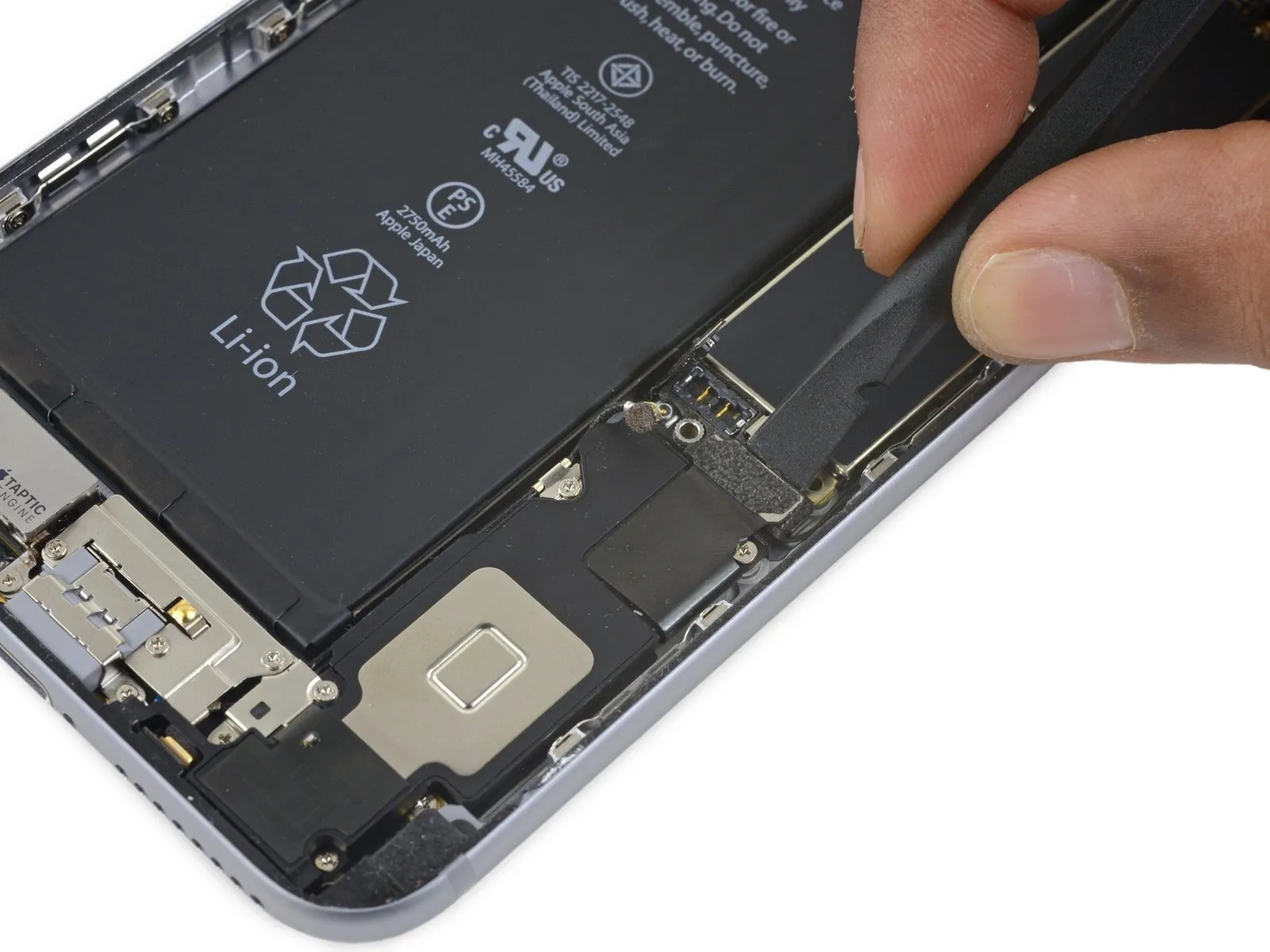
- Employ aplastic opening toolto maintain pressure on the rear enclosure as you lift the suction cup, facilitating the phone's opening.
- Refrain from detaching the display assembly entirely,as doing so risks harming the delicate data cables situated close to the upper portion of the iPhone.
Step 13

Step 14

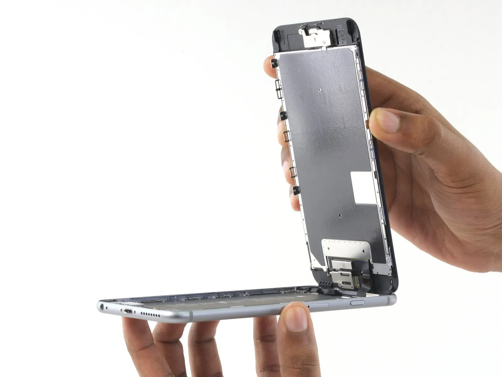

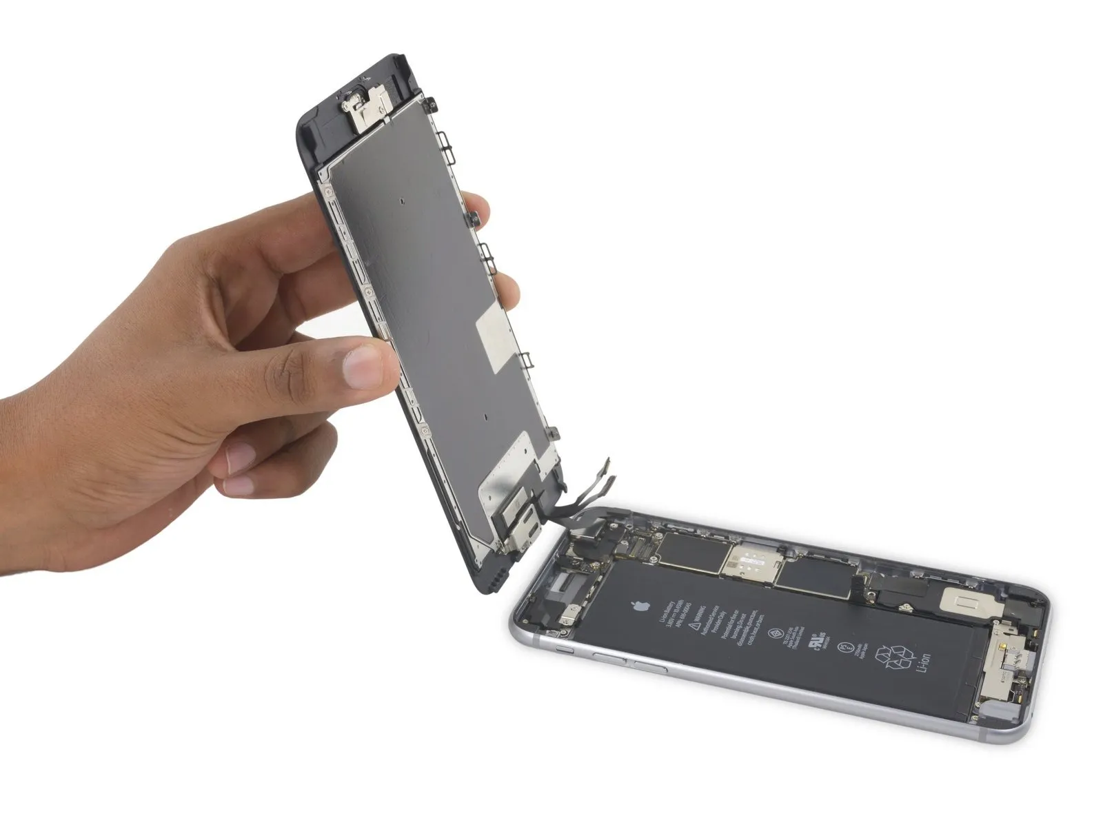
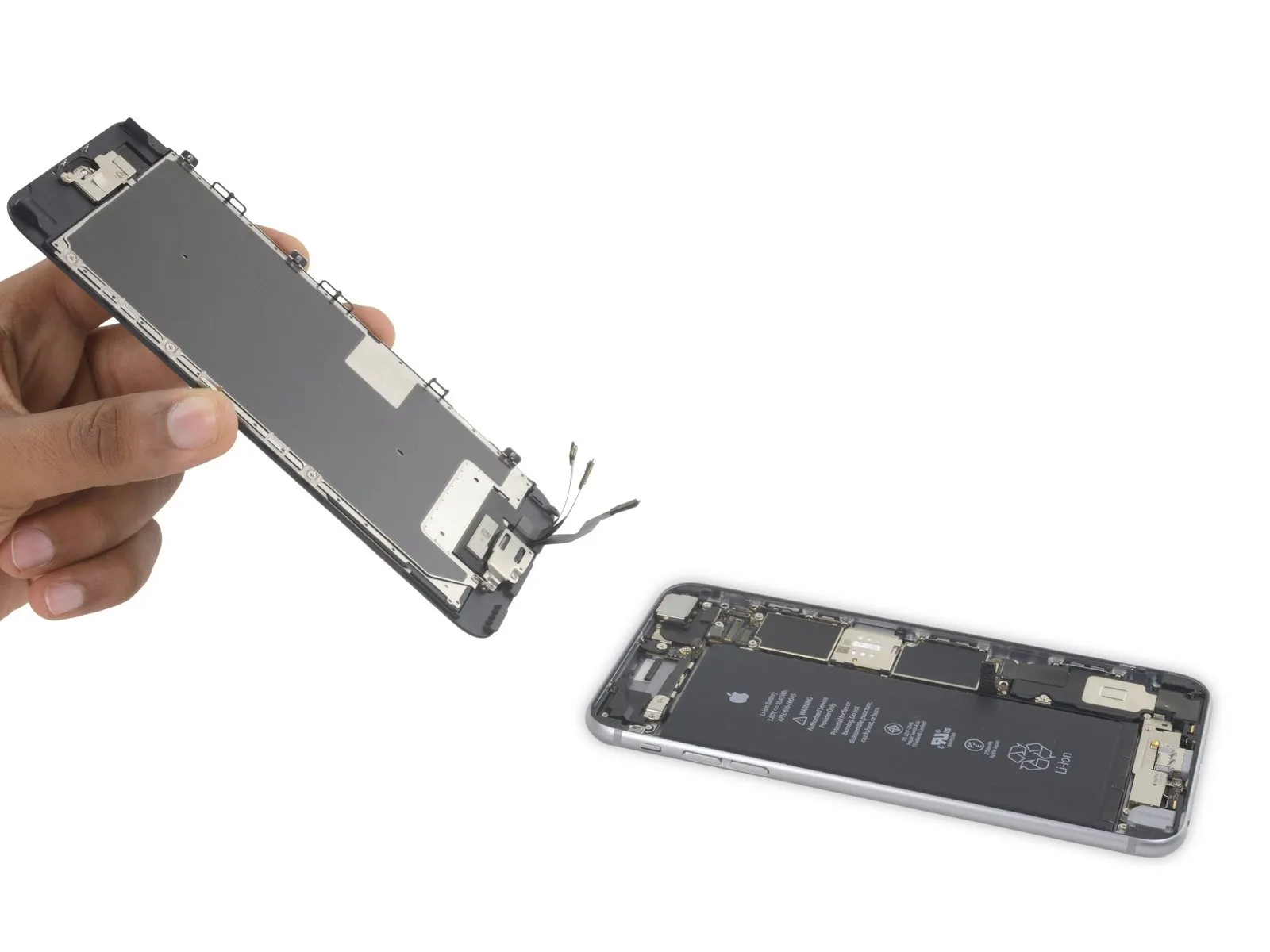
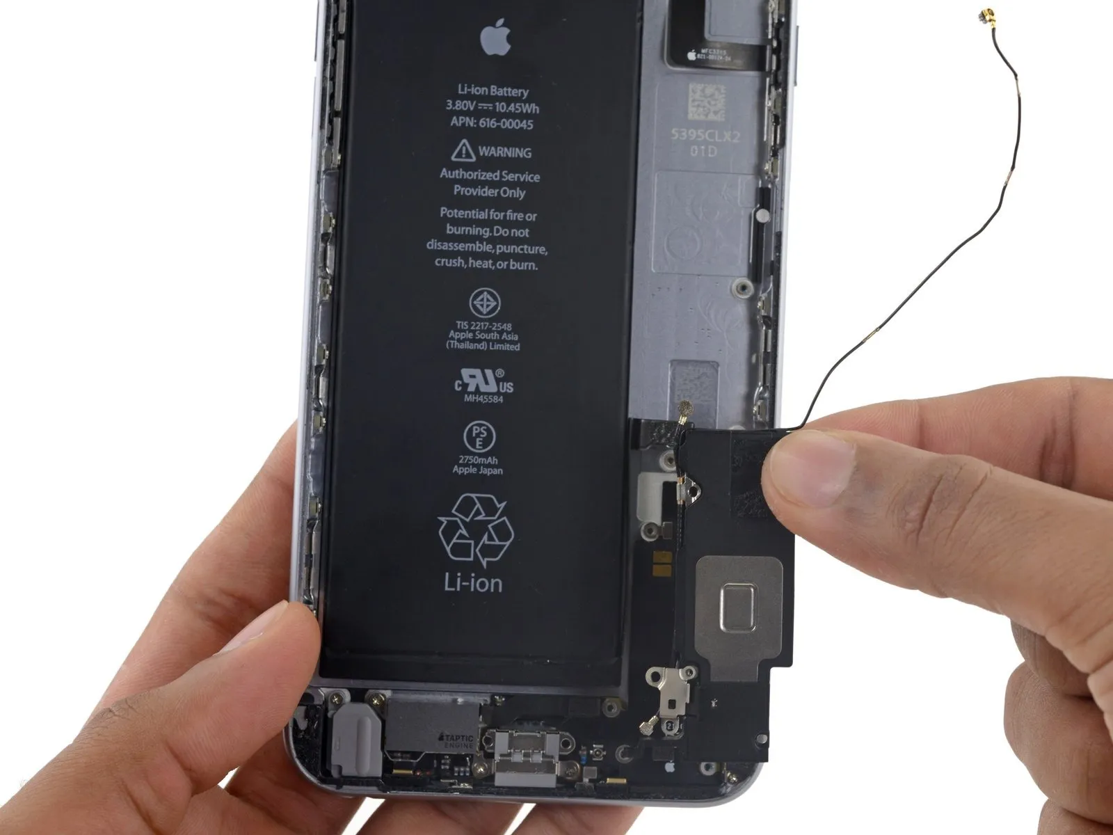
- Carefully lift the display assembly by its edges, pivoting it open like a hinge, utilizing the clips located at the top of the front panel.
- Position the opened display at approximately a 90-degree angle and secure it in a propped position to facilitate work on the device.
- Avoid exceeding a 90-degree opening angle, as the display remains tethered to the phone's upper section via the display cable, digitizer cable, and front camera cable, which are susceptible to damage.
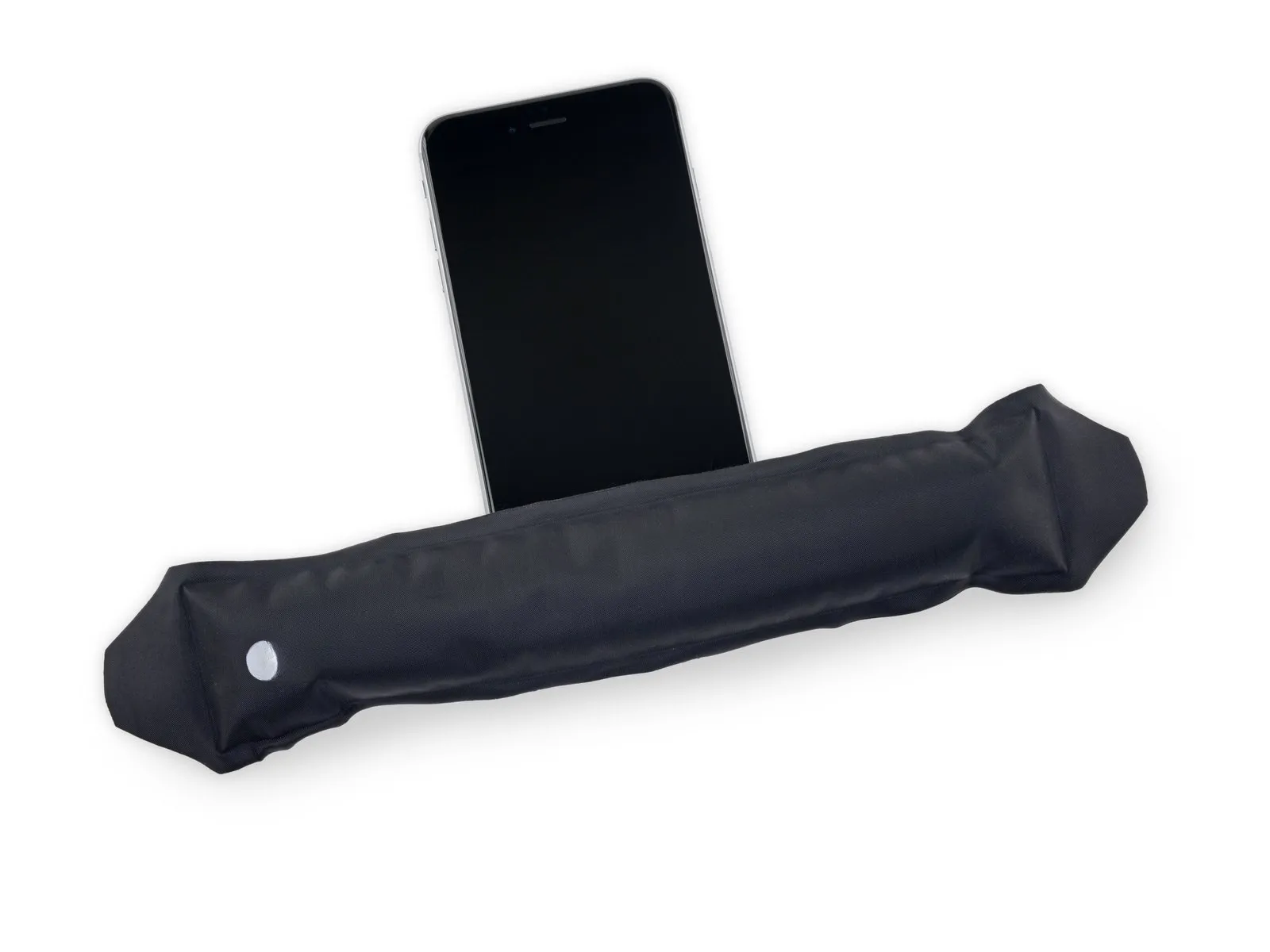
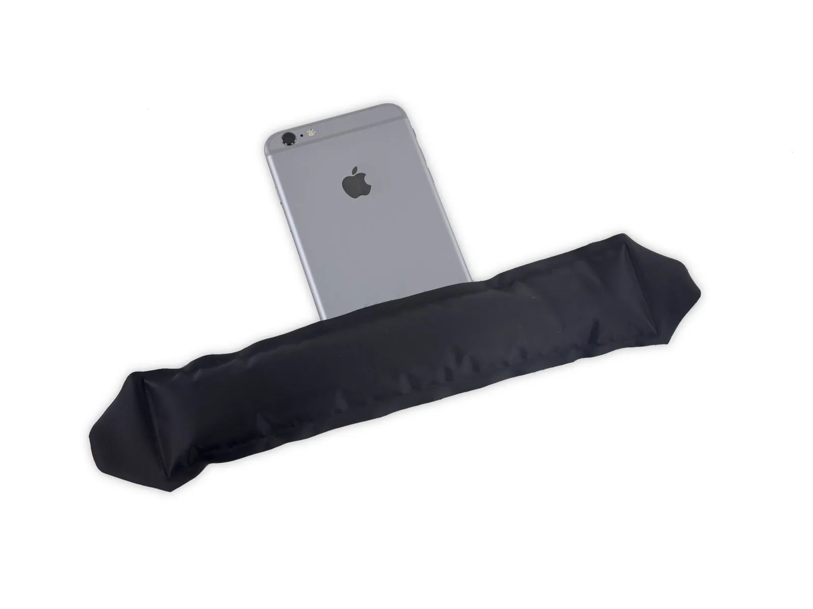
- Employ a rubber band to maintain the display's stability during the repair process, minimizing stress on the delicate display cables.
- As an alternative, an unopened, sealed beverage container can be used to provide support for the display if a rubber band is unavailable.
Step 15 | Battery Connector
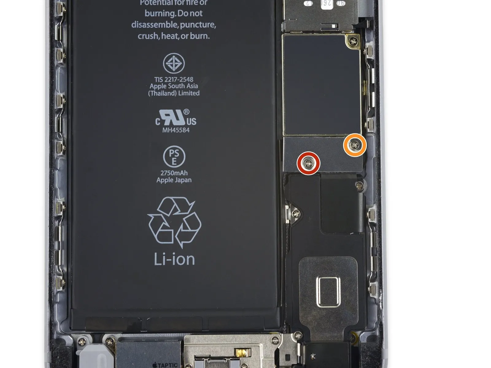
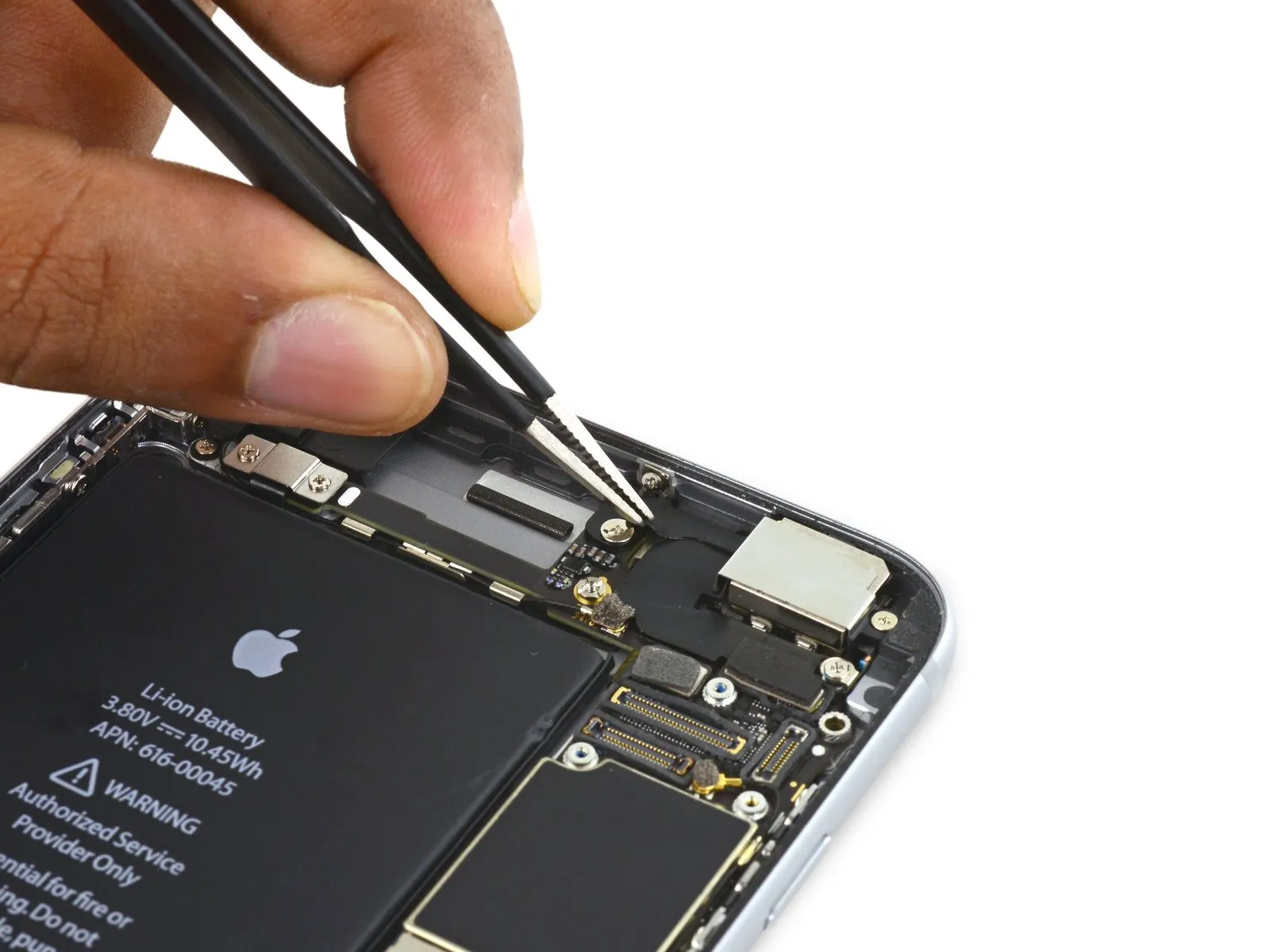
- To detach the battery connector bracket from the logic board, first, eliminate two Phillips screws that hold it in place; these screws have differing lengths.
A 2.9 mm Phillips screw is required for this step.
Additionally, a 2.3 mm Phillips screw is also needed.
During this repair process, meticulously organize all screws to ensure correct placement during reassembly; improper screw installation can lead to irreversible component failure.
Step 16
Step 17

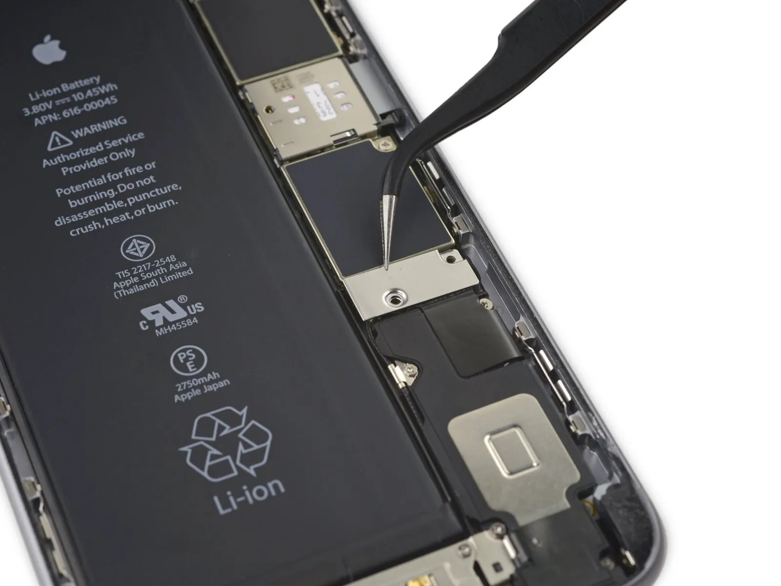
Employ a spudgerAlternatively, a clean fingernail can be utilized to release the battery connector, achieved by applying upward pressure directly above the logic board.
Step 18


To prevent unintended electrical connections, carefully restore the connector's original shape, and then activate the iPhone's power functions while performing subsequent repair steps.
Step 19 | Display Assembly
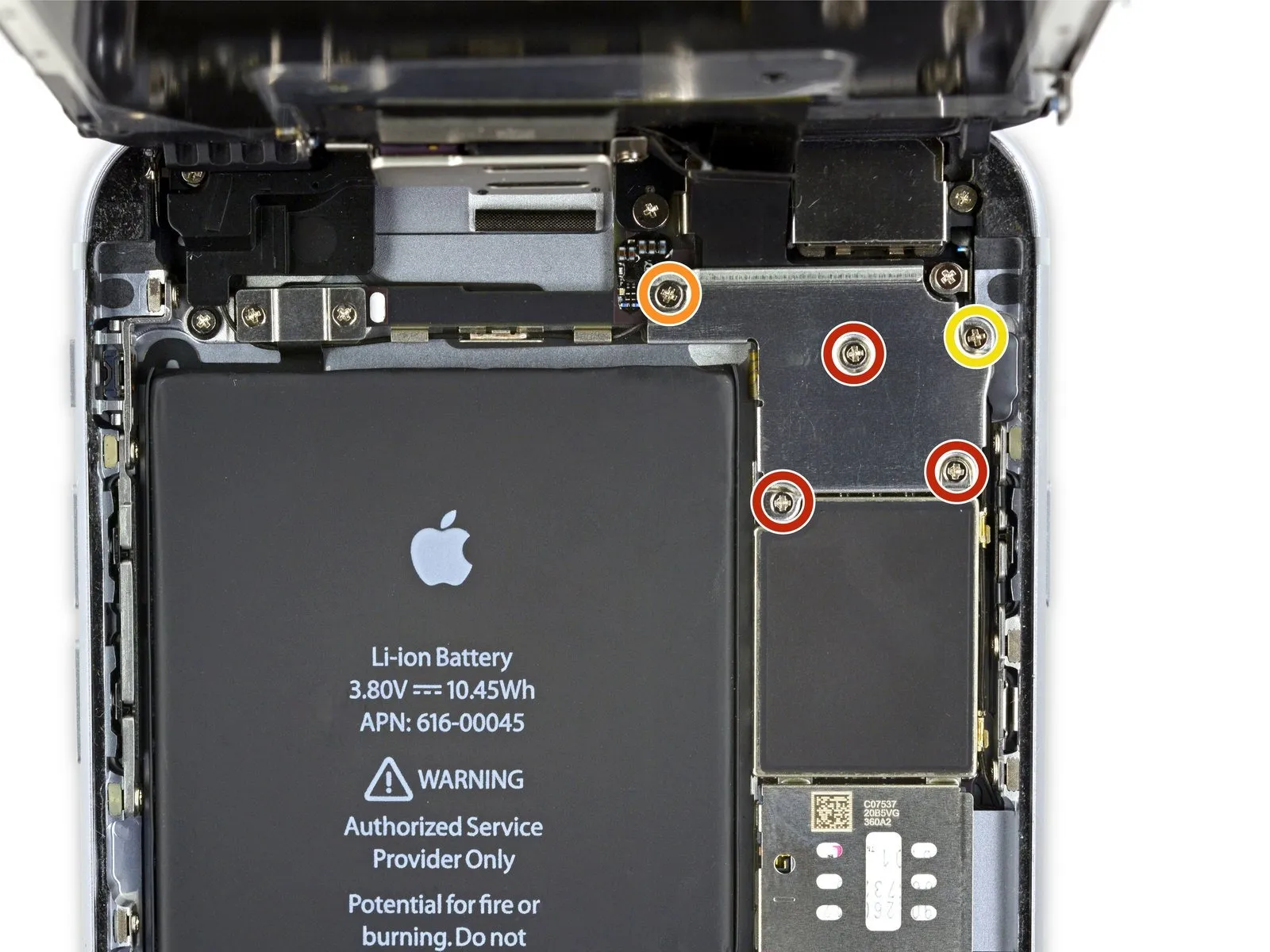
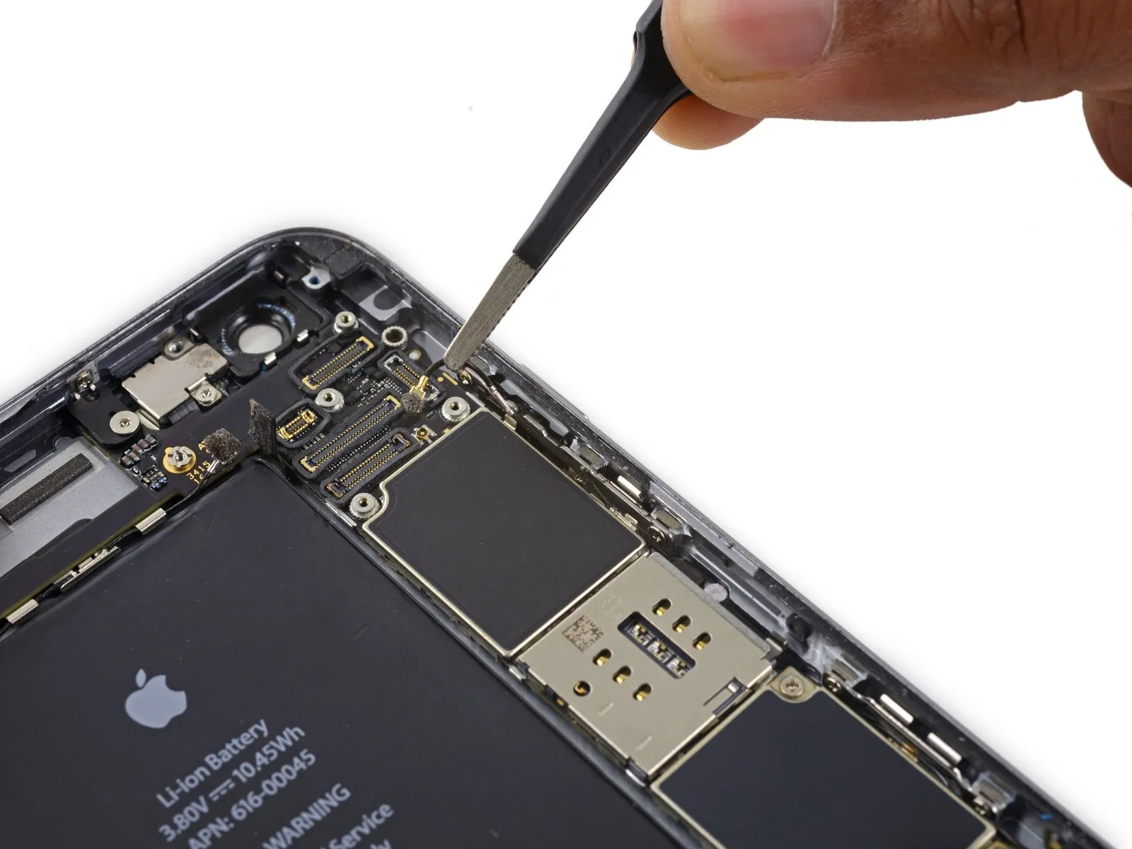
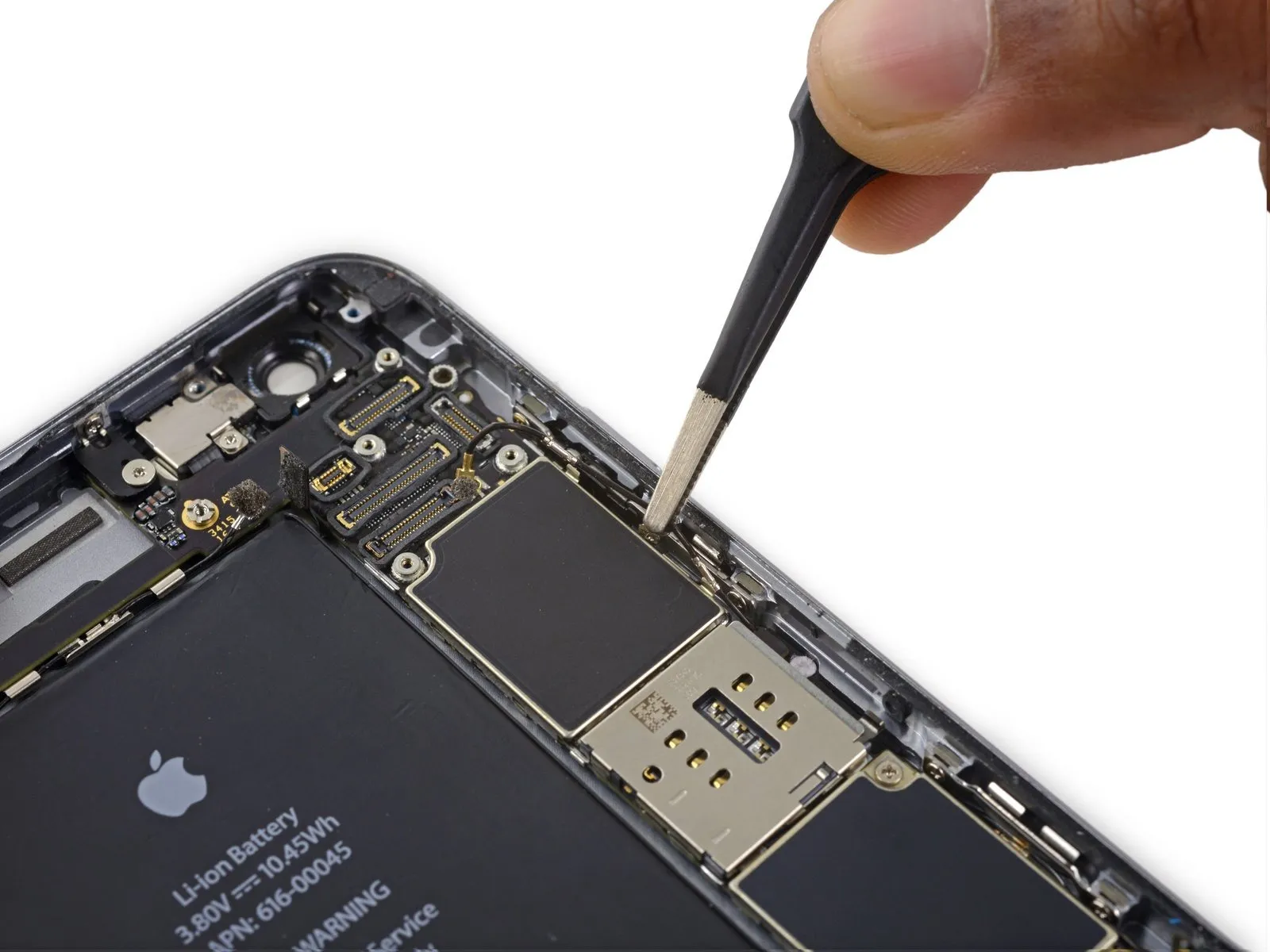
- To proceed with the repair, detach the components listed below.Utilize Phillips head screwdrivers to remove these fasteners.:
- Three screws, each measuring 1.3 millimeters in diameter, must be extracted.
- A single screw with a 1.6-millimeter diameter is also required for removal.
- Additionally, a 3.0-millimeter screw needs to be taken out.
When reassembling the device, ensuring the correct placement of this3.0-millimeter screw within the upper-right portion of the bracket is essential; incorrect positioning could potentially harm the logic board.
Step 20
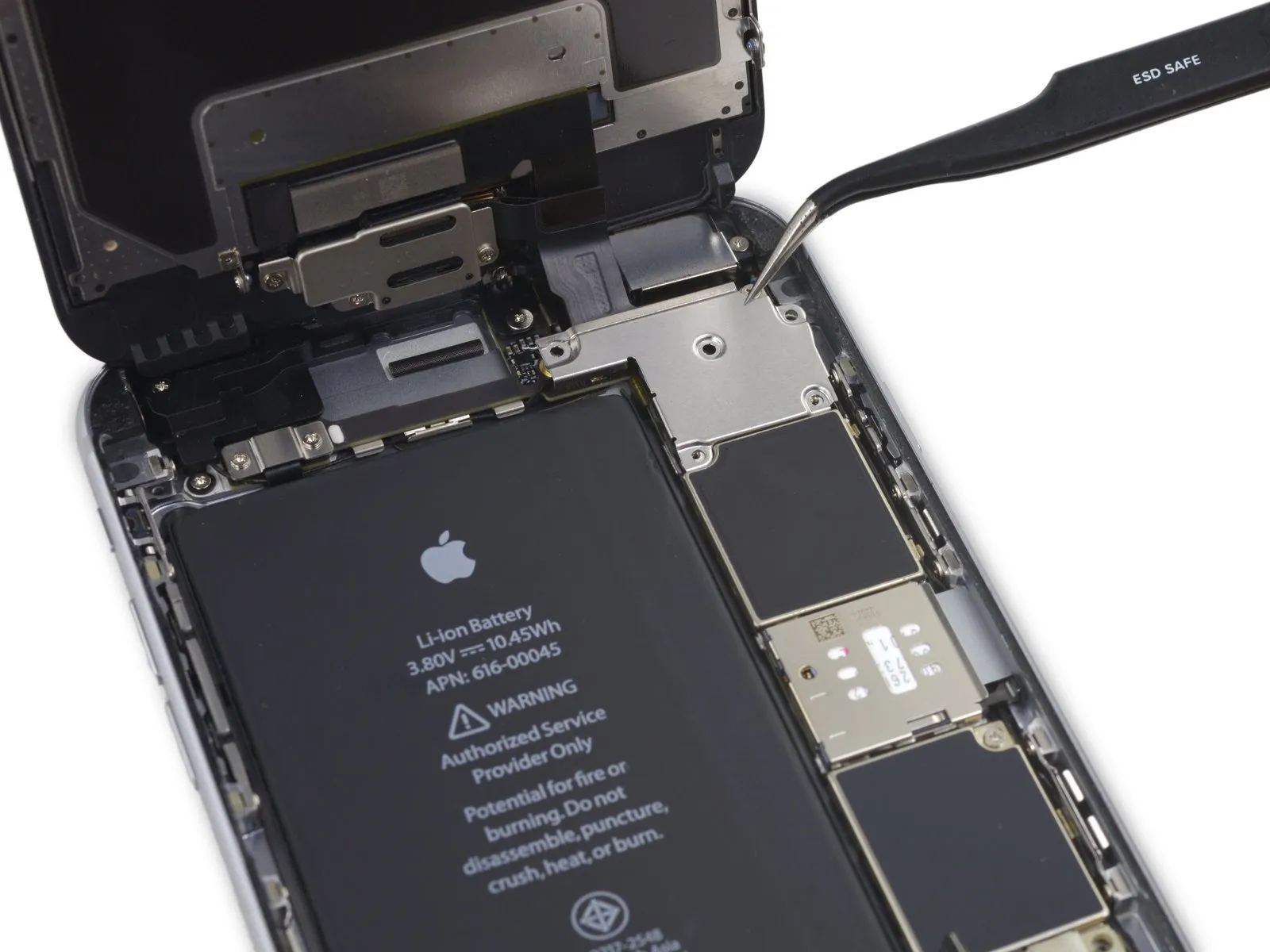

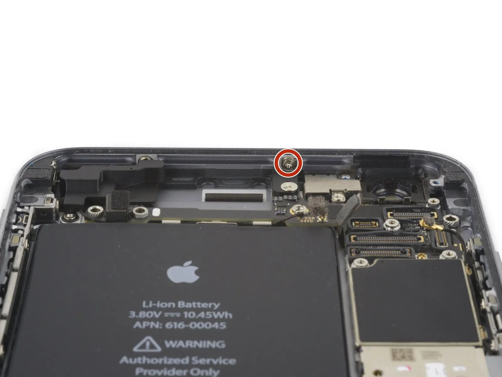
Detach the securing bracket that holds the display cable in place.
Step 21

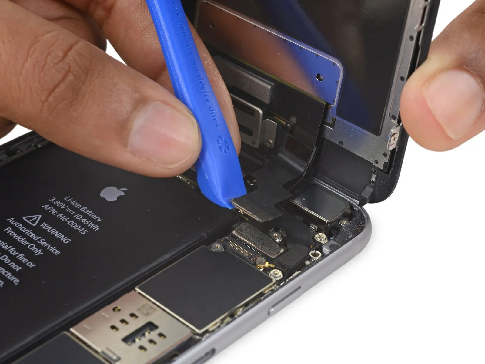
- Exercise caution, ensuring that prying force is applied solely to the connector body, avoiding damage to the socket situated on the logic board.
- Employ a plastic opening toolfor the purpose of detaching the front-facing camera and sensor cable connector.
Step 22
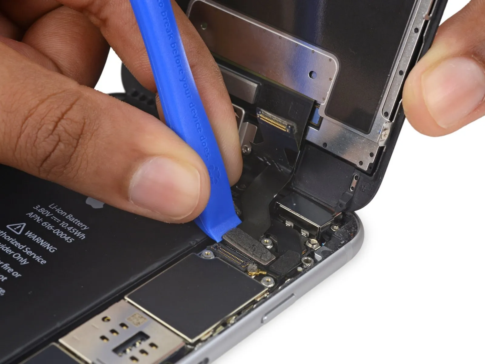

- Employ a plastic opening tool to release the digitizer cable's connection, lifting it vertically from its position within the socket on the logic board.A plastic opening tool is required for this step.To ensure proper reattachment, avoid applying pressure to the central area of the digitizer cable connector; instead, apply force to one end, then the opposing end, as this prevents bending and potential component failure.
- Central pressure on the connector can compromise the component's integrity.Damage to the digitizer may result from improper handling.This completes the procedure.
Step 23

- Prior to detaching or reattaching the cable within this procedure, confirm the battery's power is completely removed.
- To release the home button/fingerprint sensor cable, carefully lift it vertically away from its connection point on the logic board.
Step 24
- Detach the display unit from the device.
- When putting the device back together, halt at this stage should you choose to substitute the adhesive securing the display's perimeter.
Step 25 | iSight Camera

Step 26
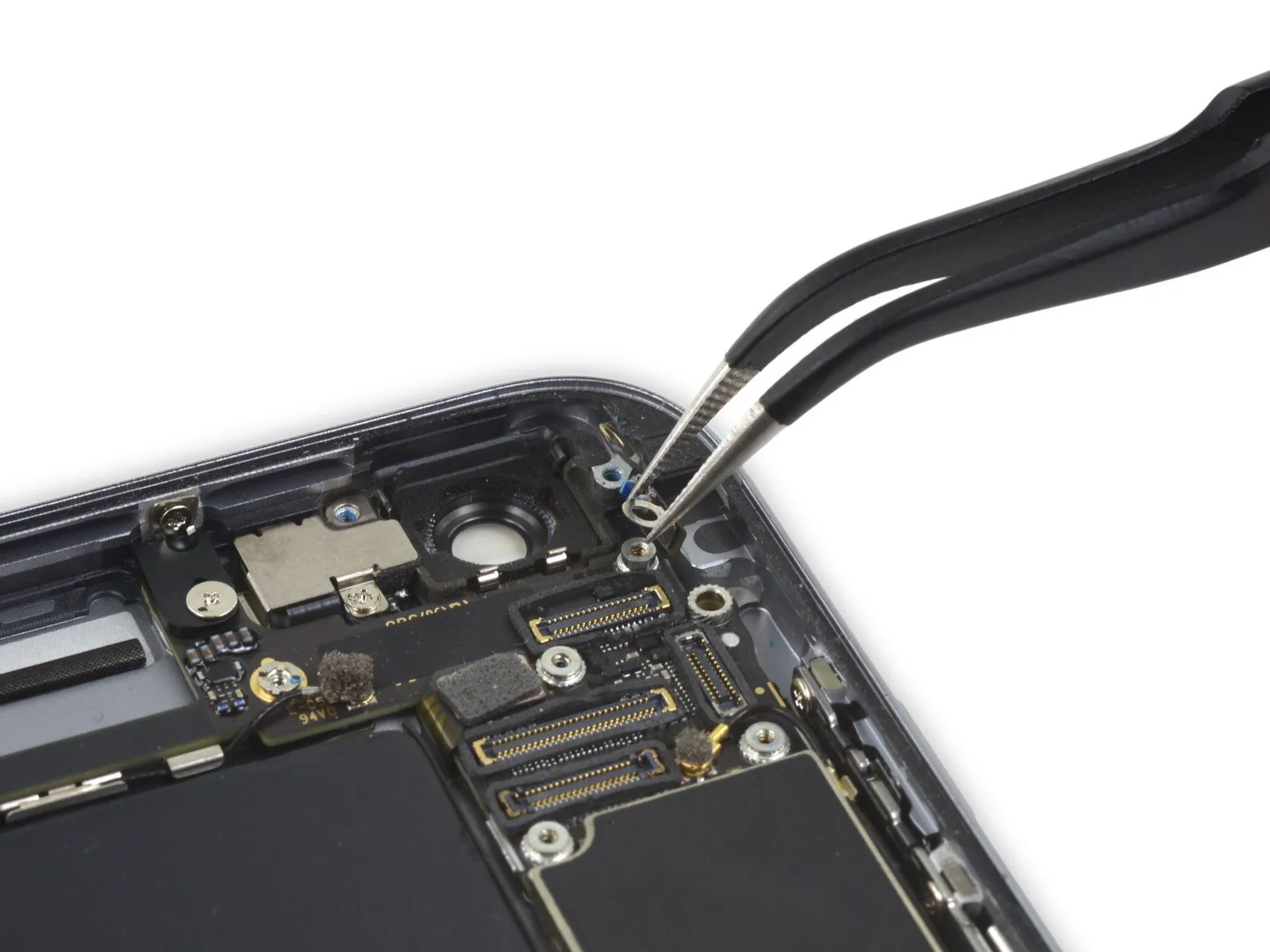
- To detach the camera bracket, eliminate the Phillips screws listed below:
- A 1.9-millimeter screw must be taken out.
- A 2.4-millimeter screw also requires removal.
Step 27
Step 28
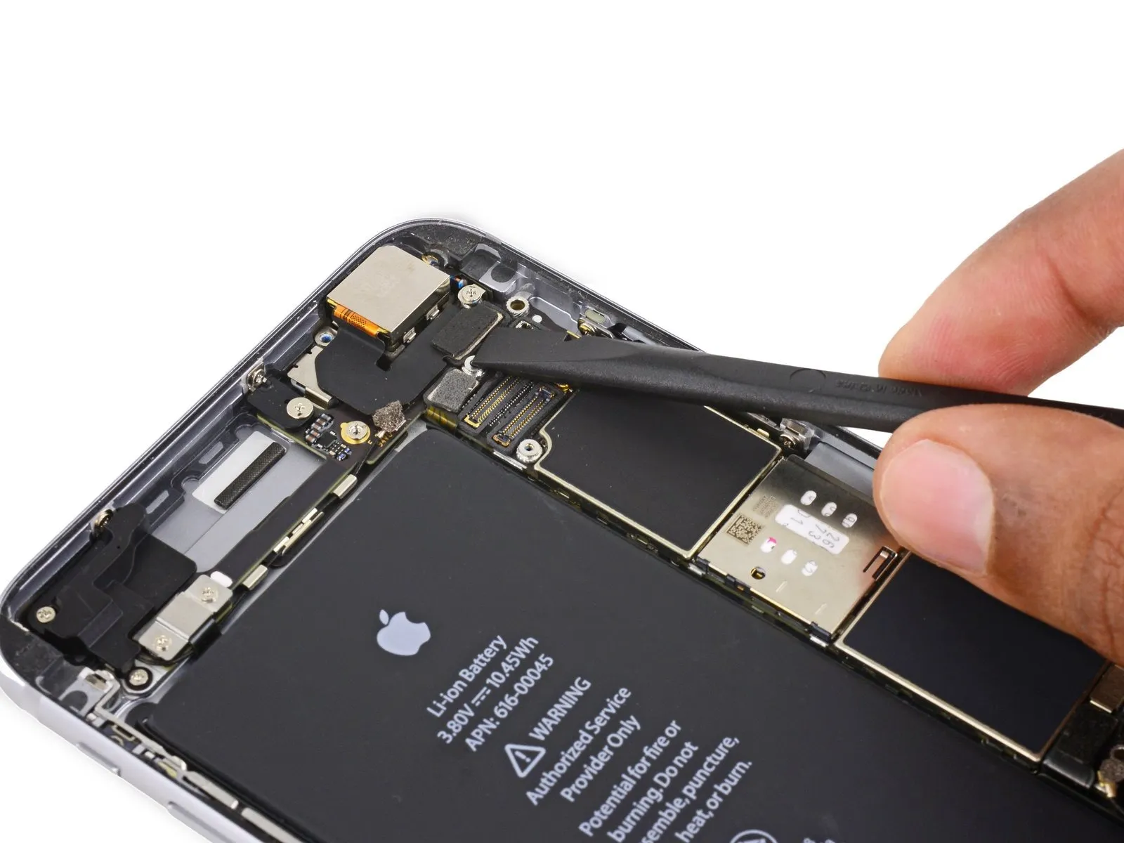
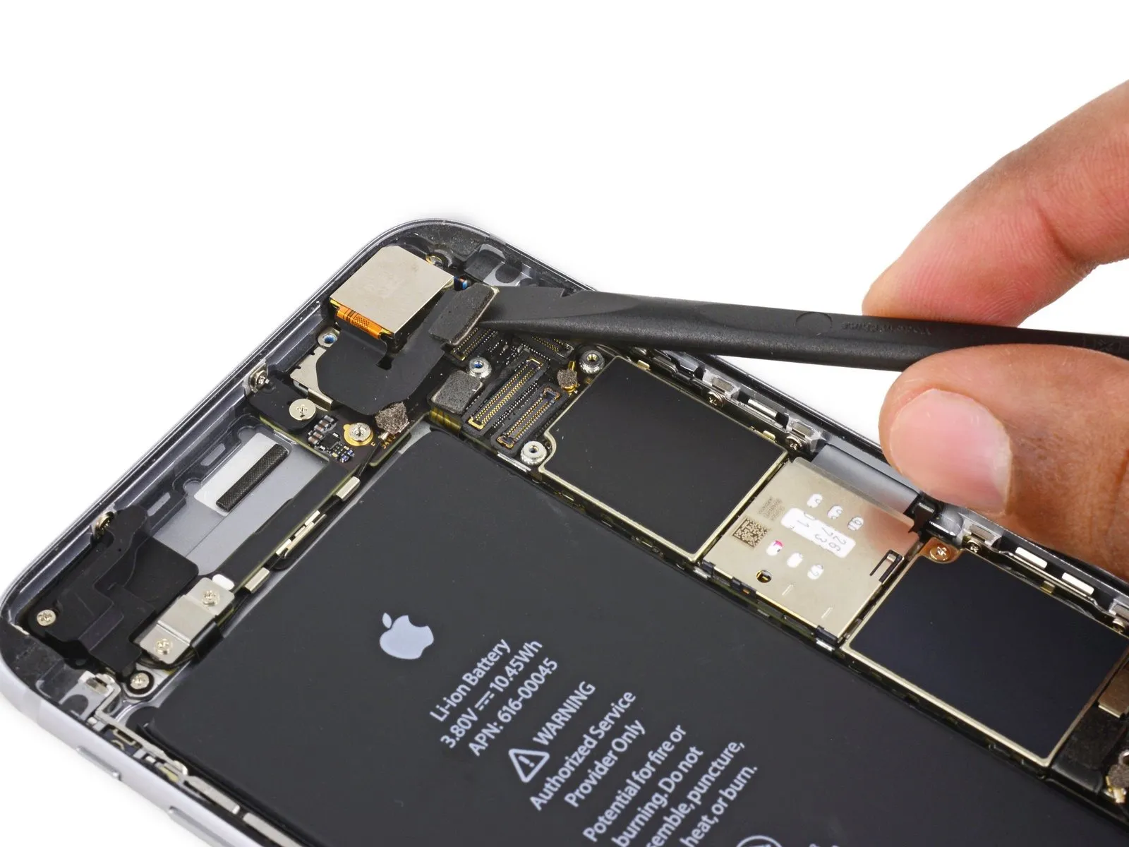
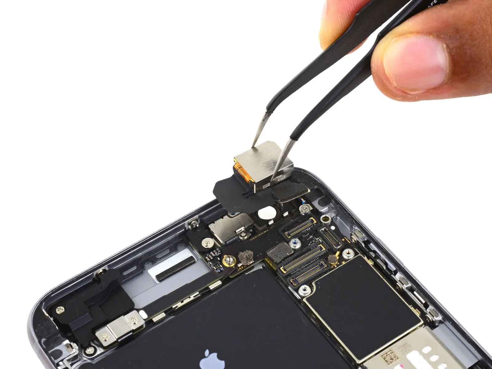
- To prevent damage, detach the iSight camera connector from its corresponding receptacle on the logic board.
Exercise caution to lift solely the connector itself, avoiding any movement of the socket secured to the logic board.
Step 29

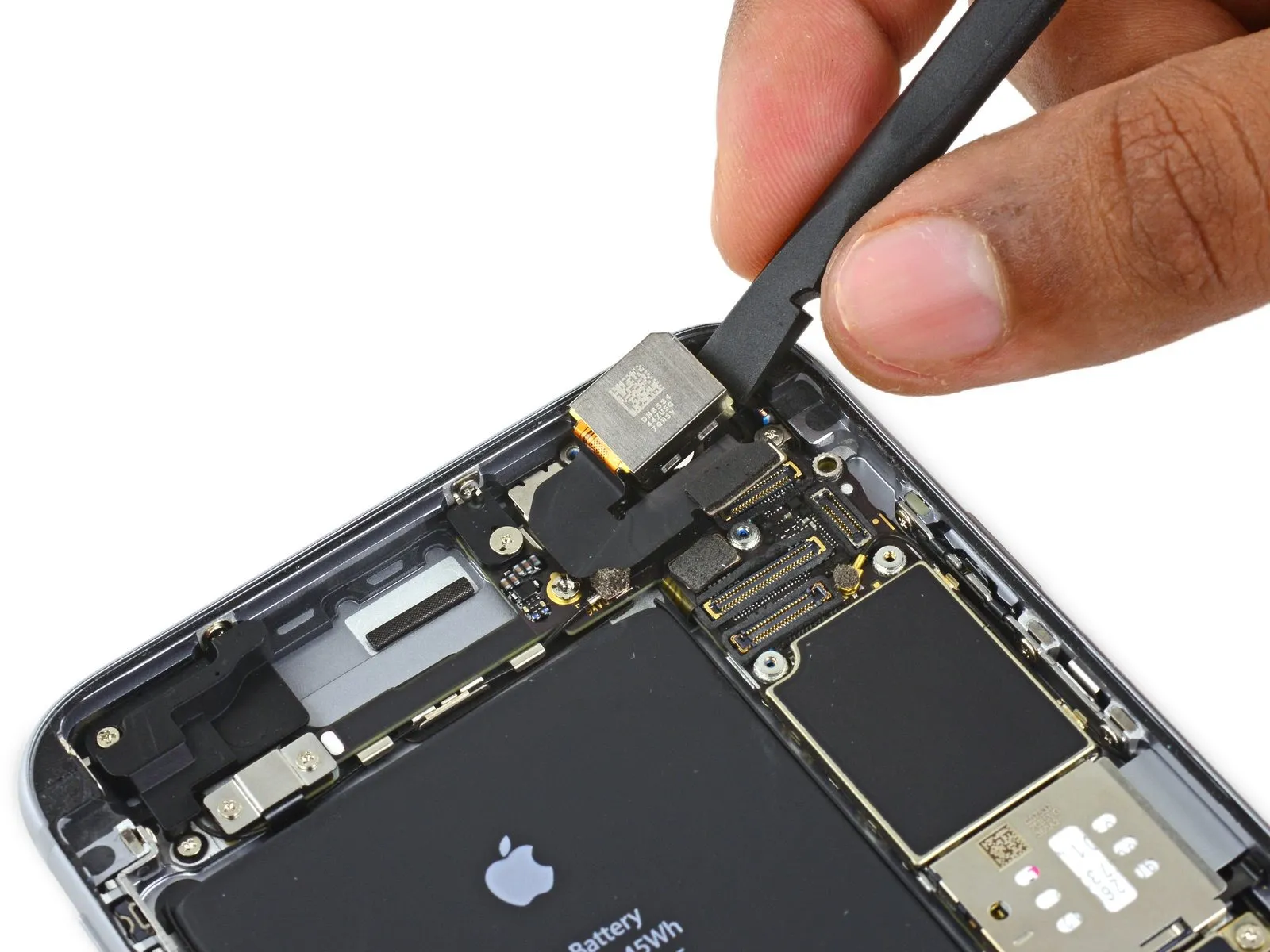
- Employ the planar extremity of the specified tool to introduce separation between the iSight camera assembly and the device's posterior enclosure.spudgerCarefully disengage the camera from its mounting structure using a prying motion.
- Gently apply force to extract the camera from its housing.
Step 30
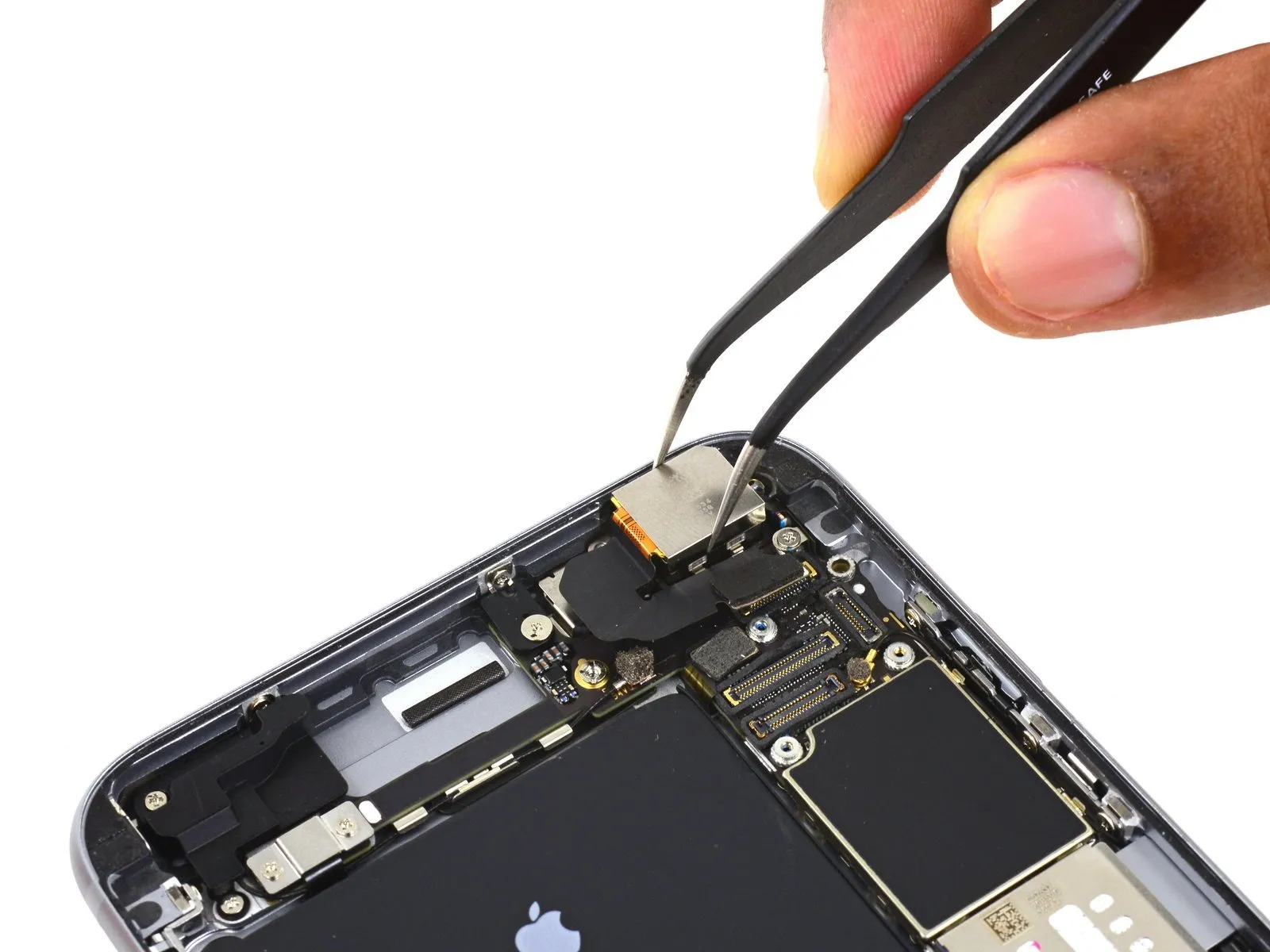
- Detach the iSight camera assembly.
Step 31 | SIM Tray


- Position a SIM eject tool within the aperture located on the SIM tray.
Apply pressure to release the SIM tray from its housing.
Step 32

- Extract the SIM card from its tray.
During the process of placing the SIM tray back into the device, confirm that the tray's orientation aligns with the SIM eject aperture positioned at the lower edge.
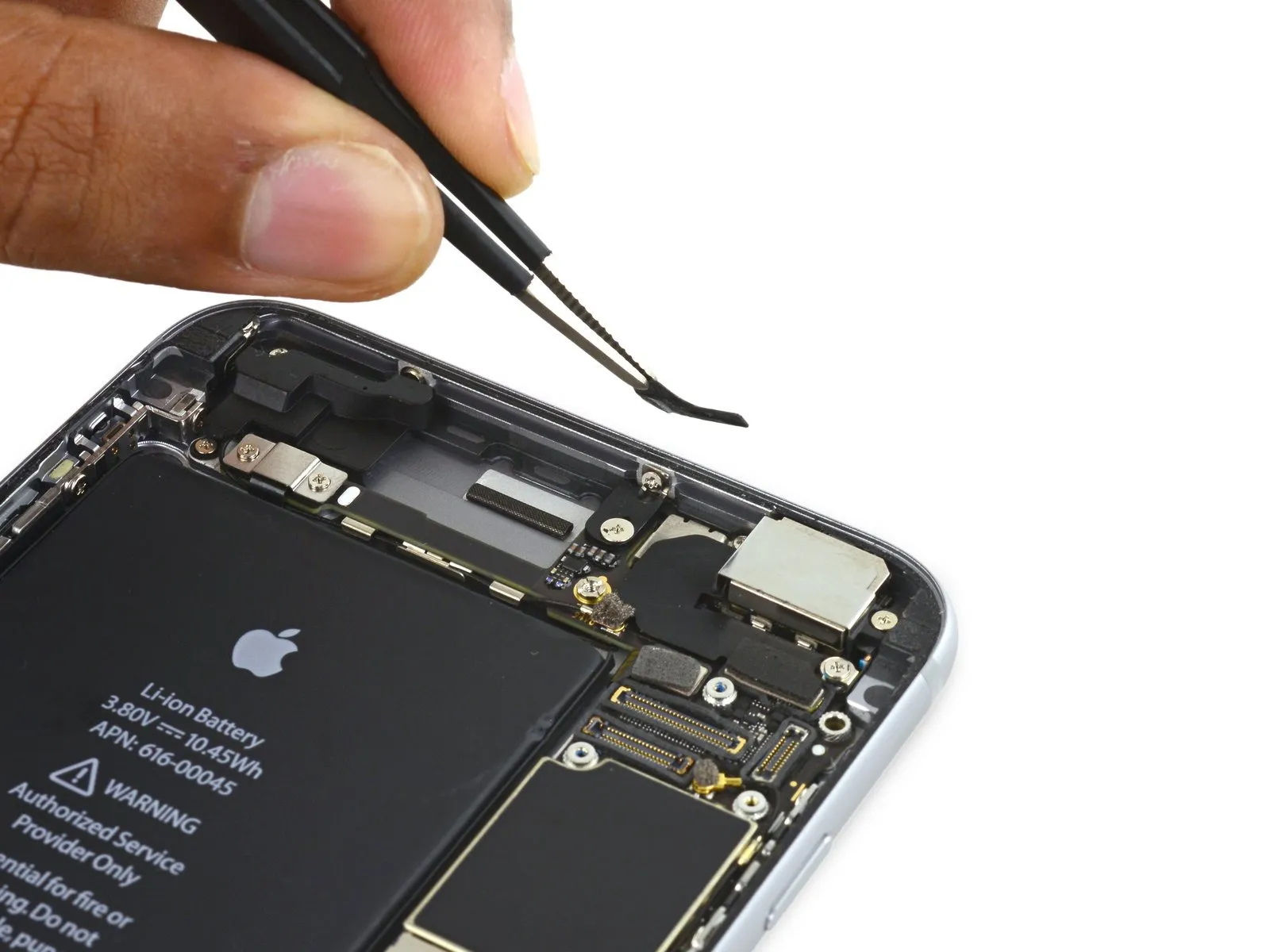
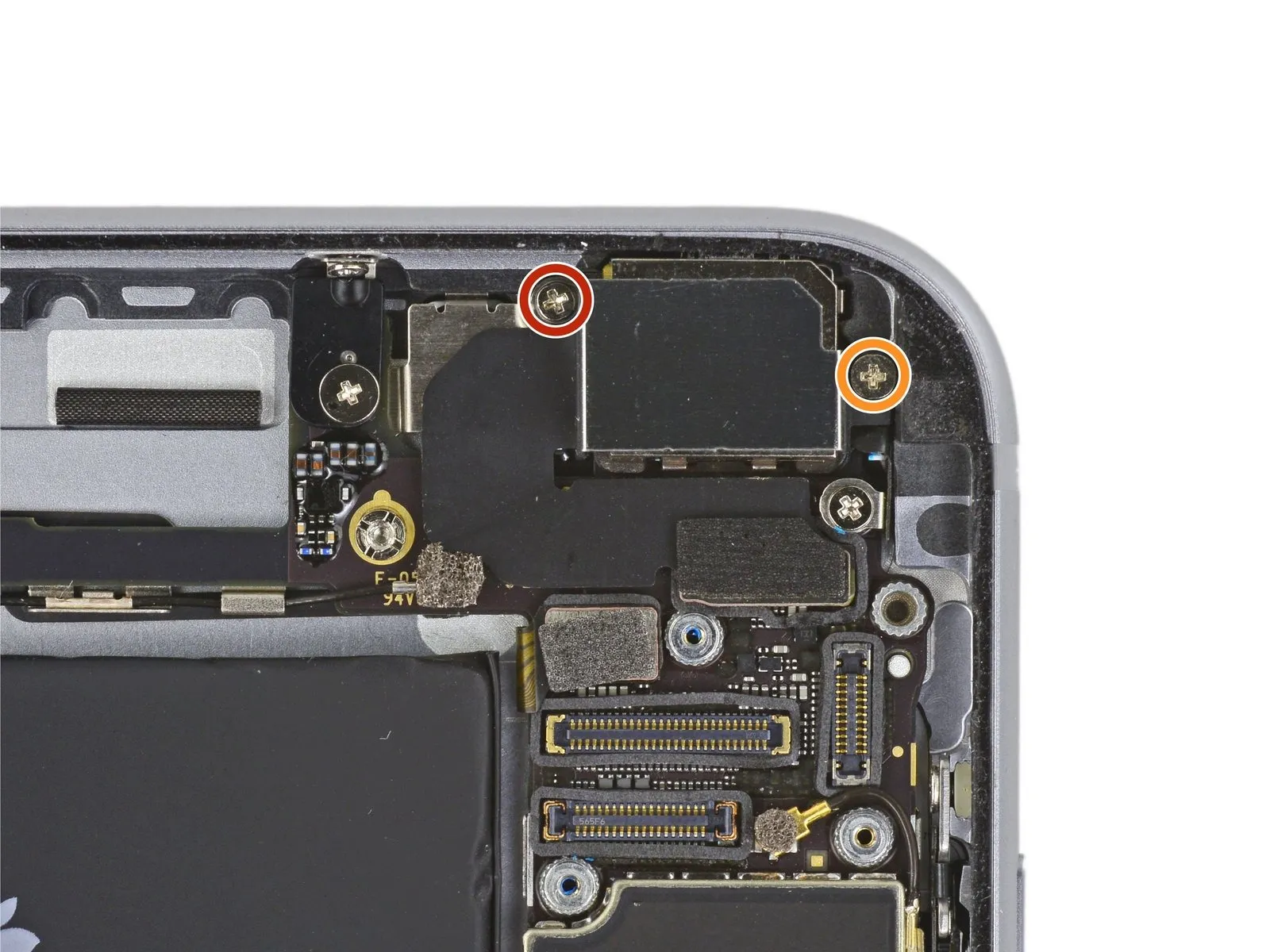
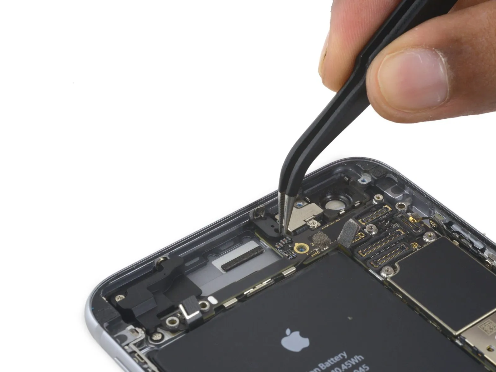
Step 33 | Logic Board

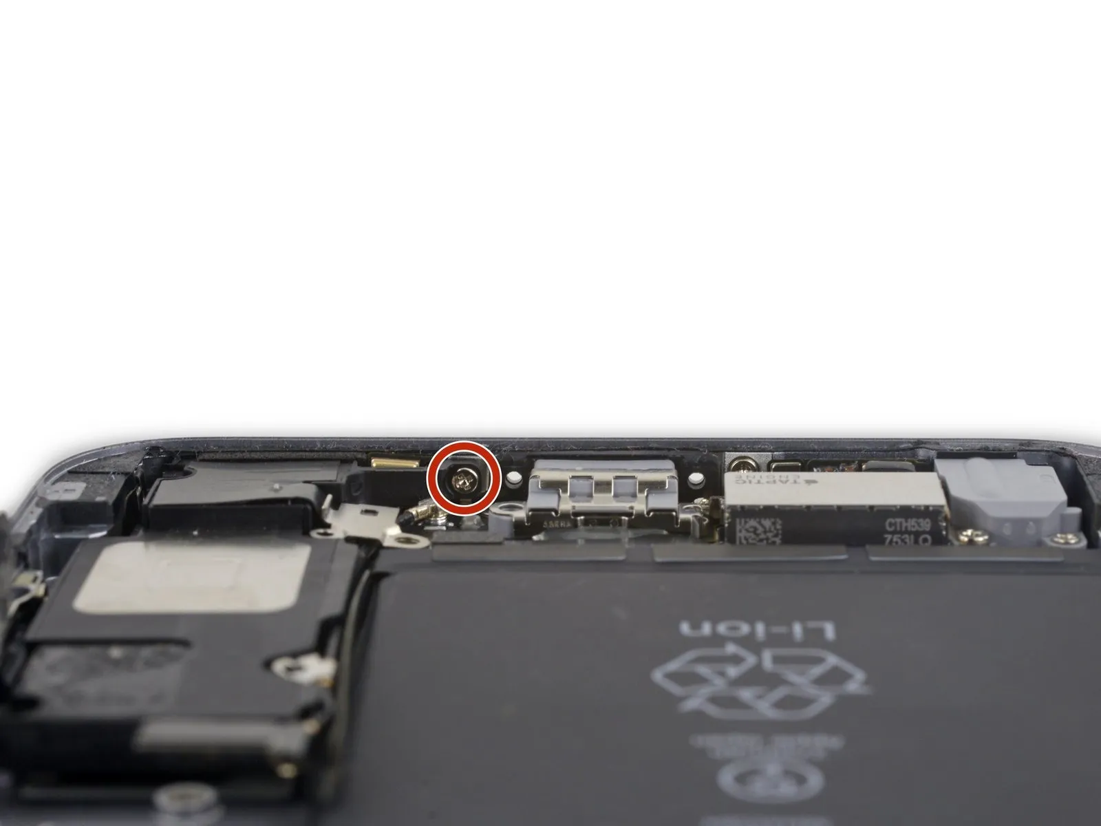
- Detach the solitary 1.4 mm Phillips screw securing the NFC bracket's position.
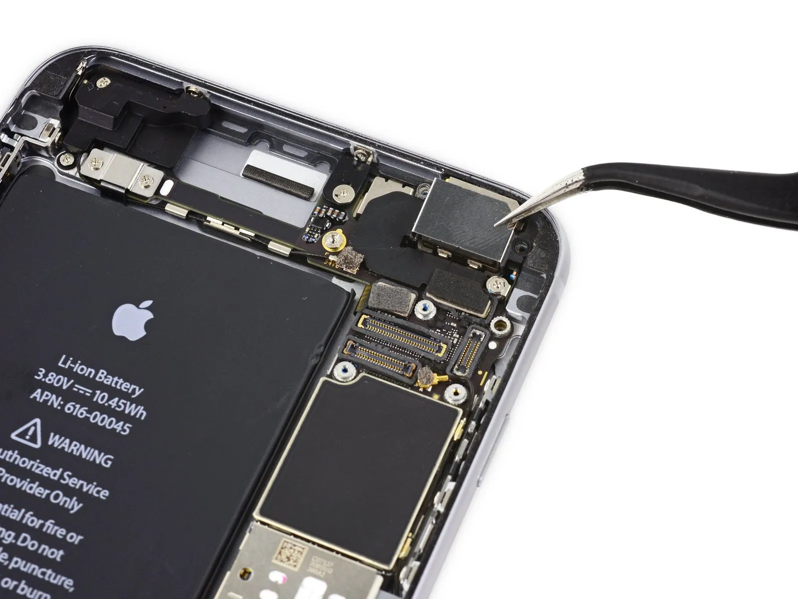
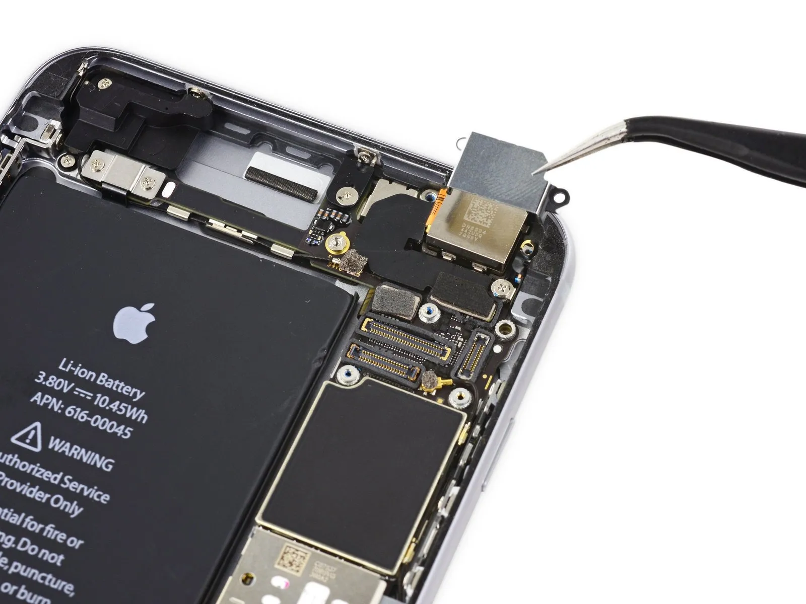
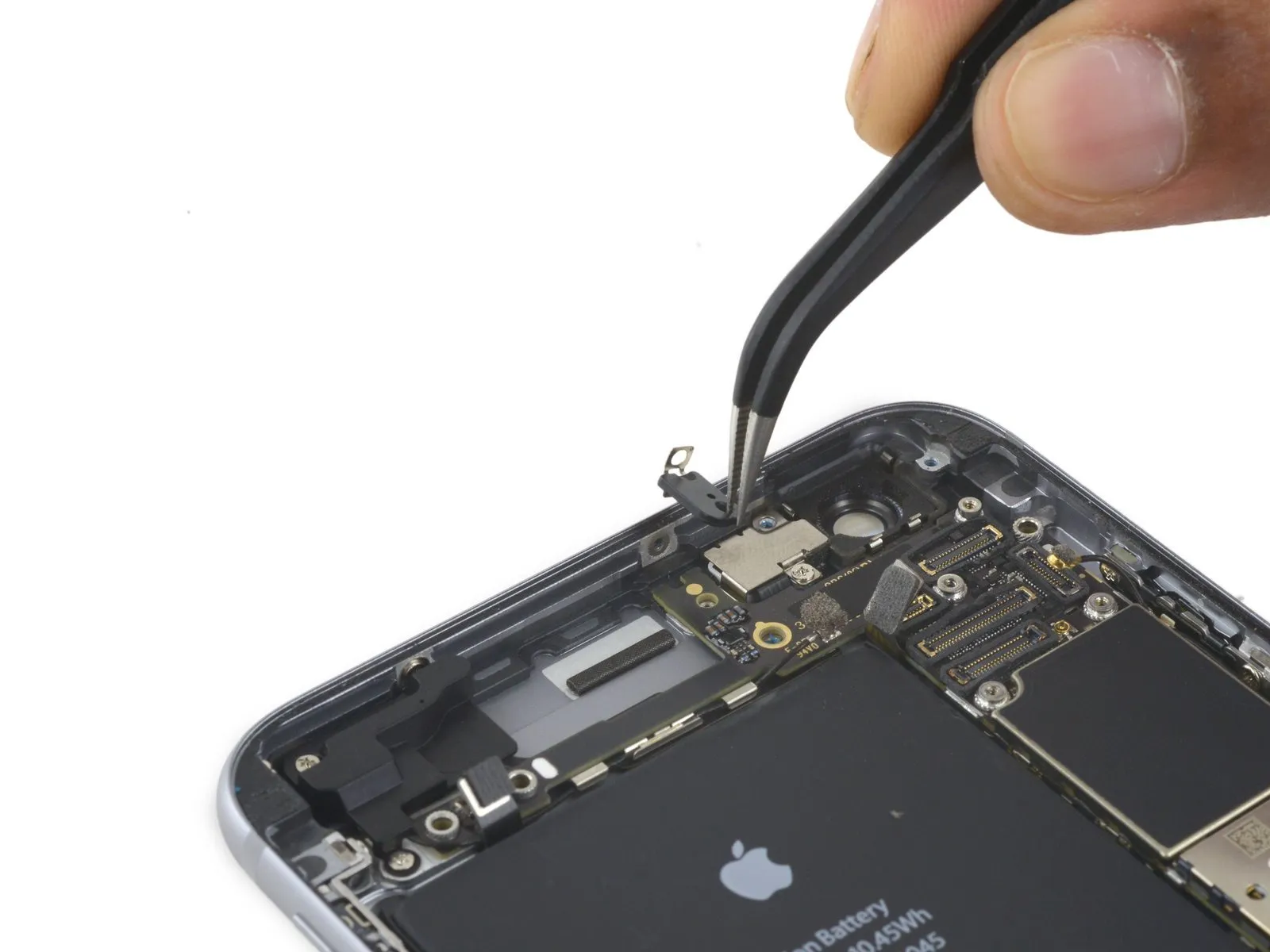
Step 34

- Detach the near-field communication antenna assembly.
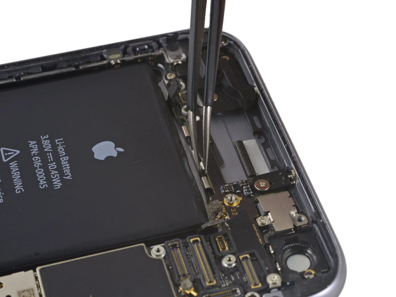
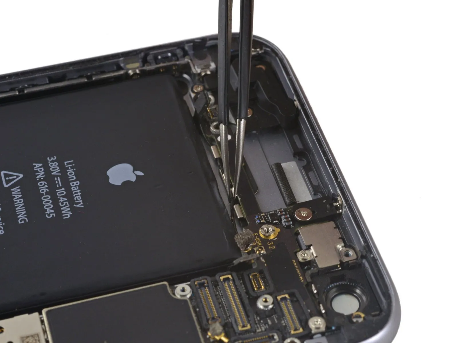
Step 35
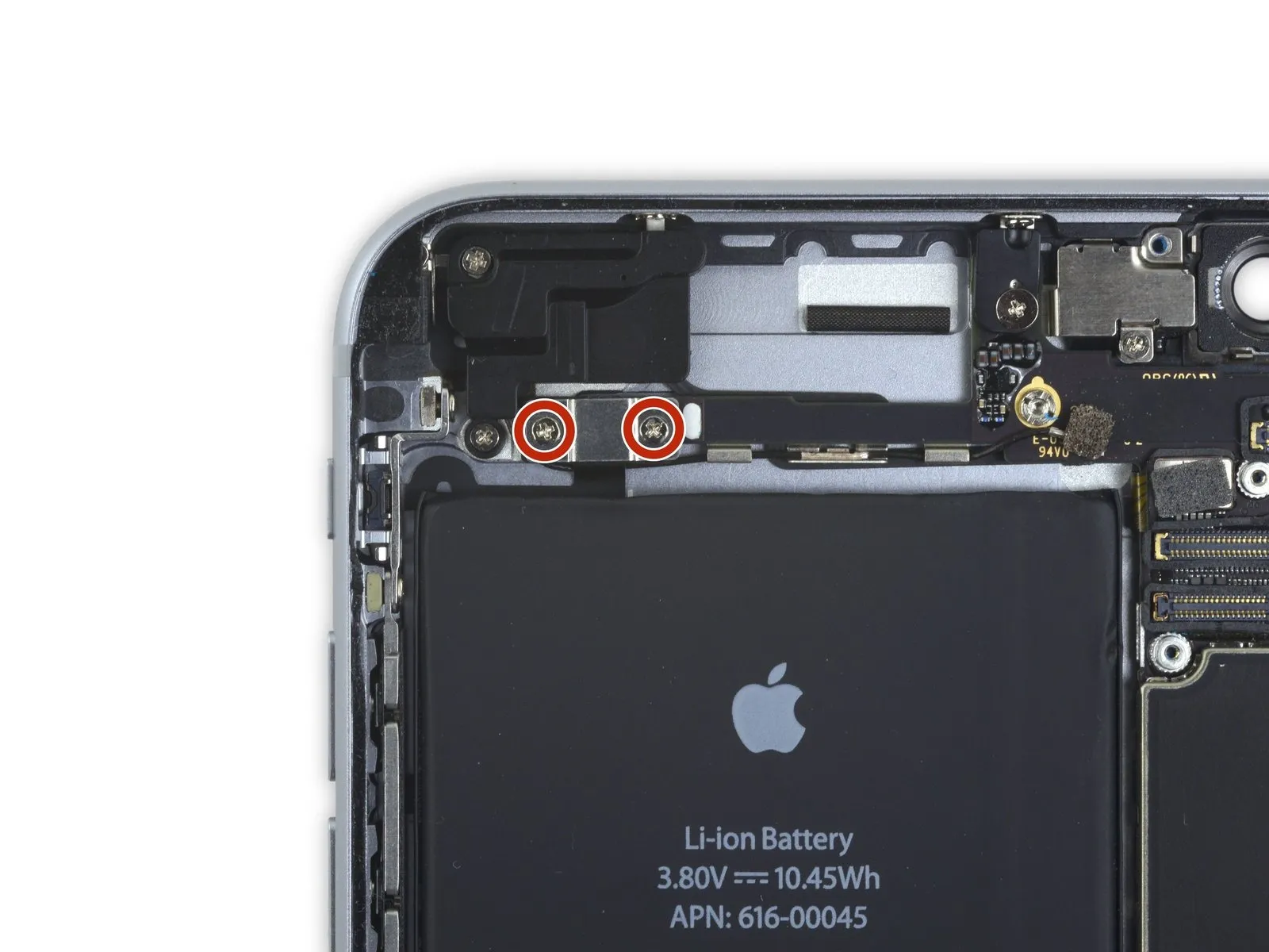
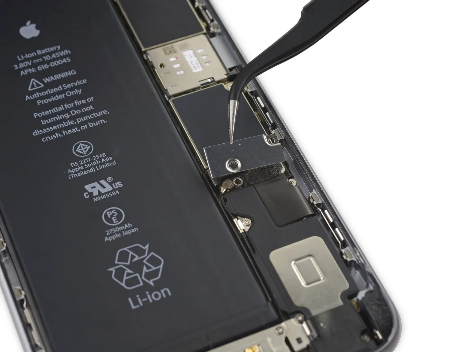
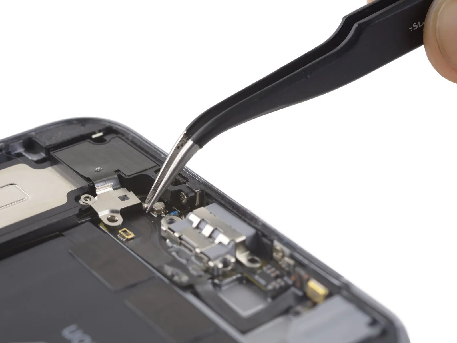
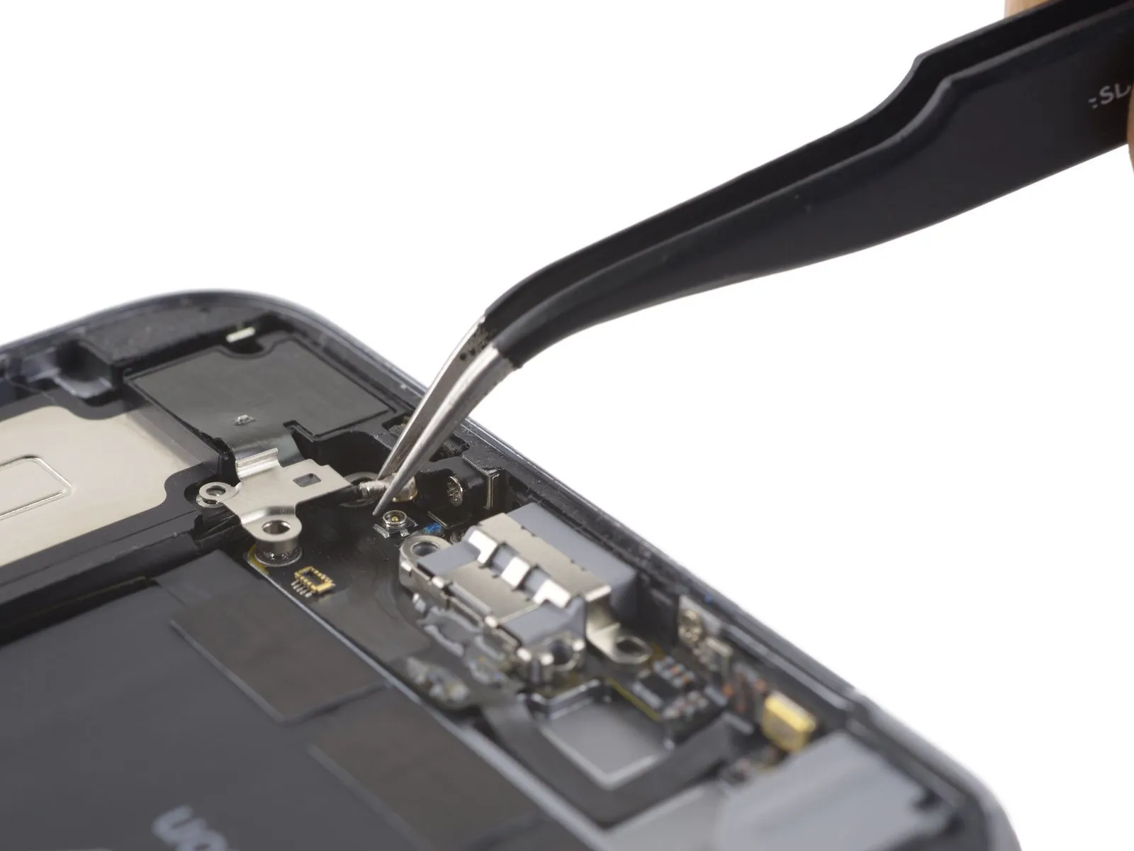
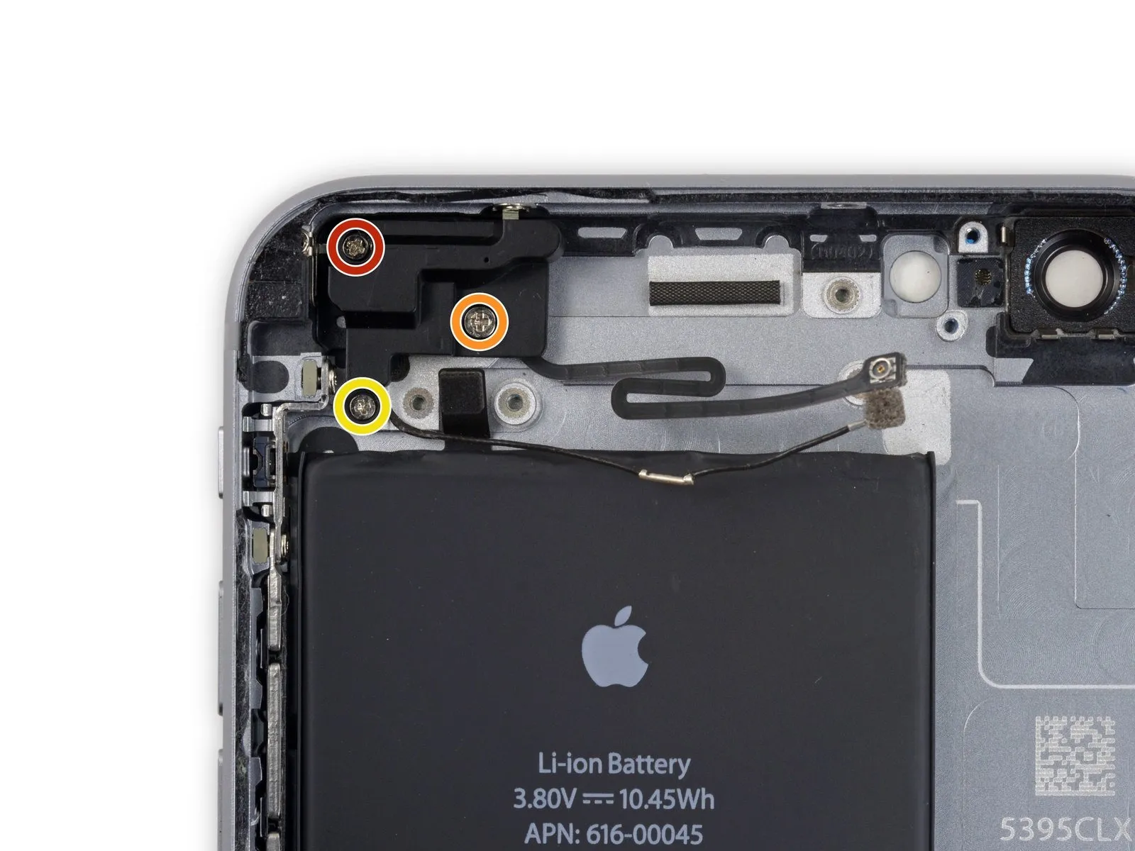
- Detach the audio control cable bracket from the logic board by eliminating the two2.7 mm Phillips screwsthat hold it in place.
Step 36

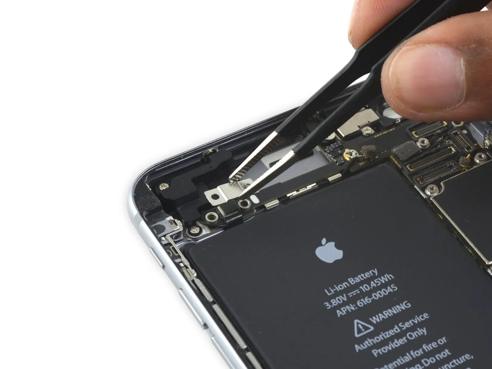
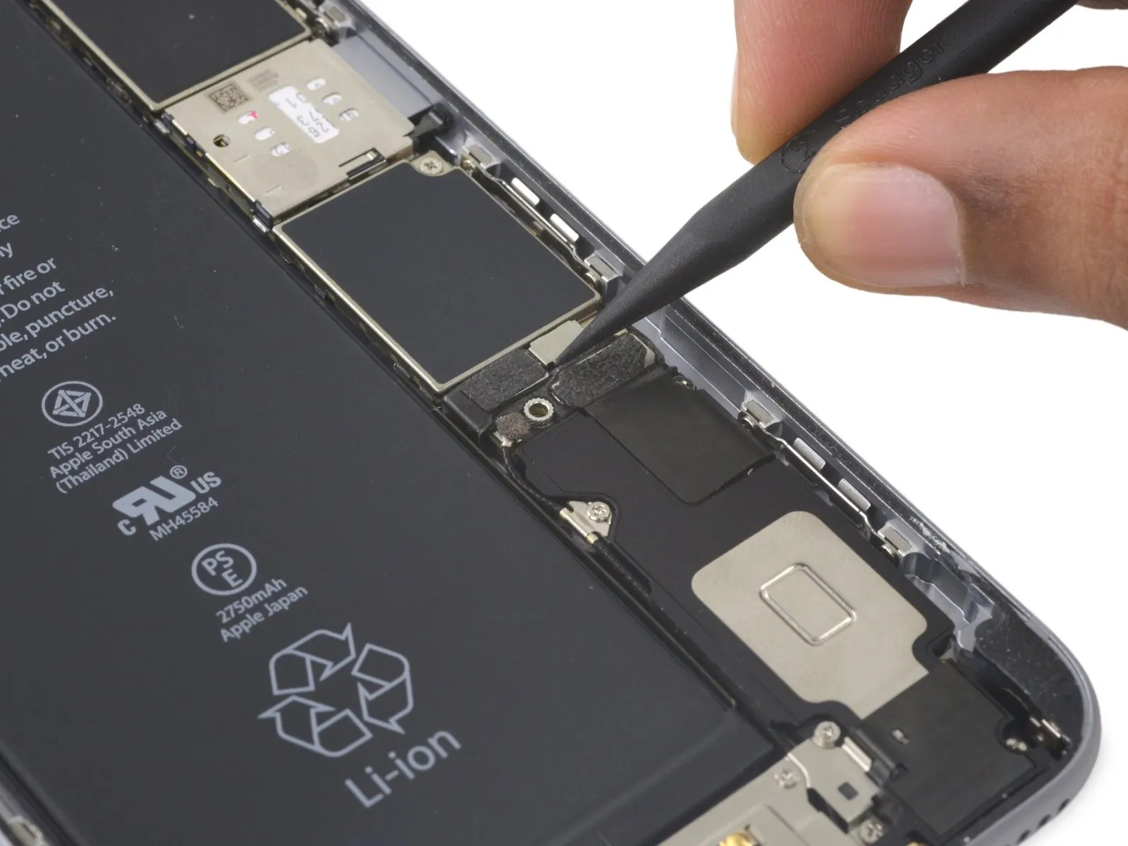
Step 37

- To detach theaudio control cablerelease its connector from the logic board's socket by applying upward force.
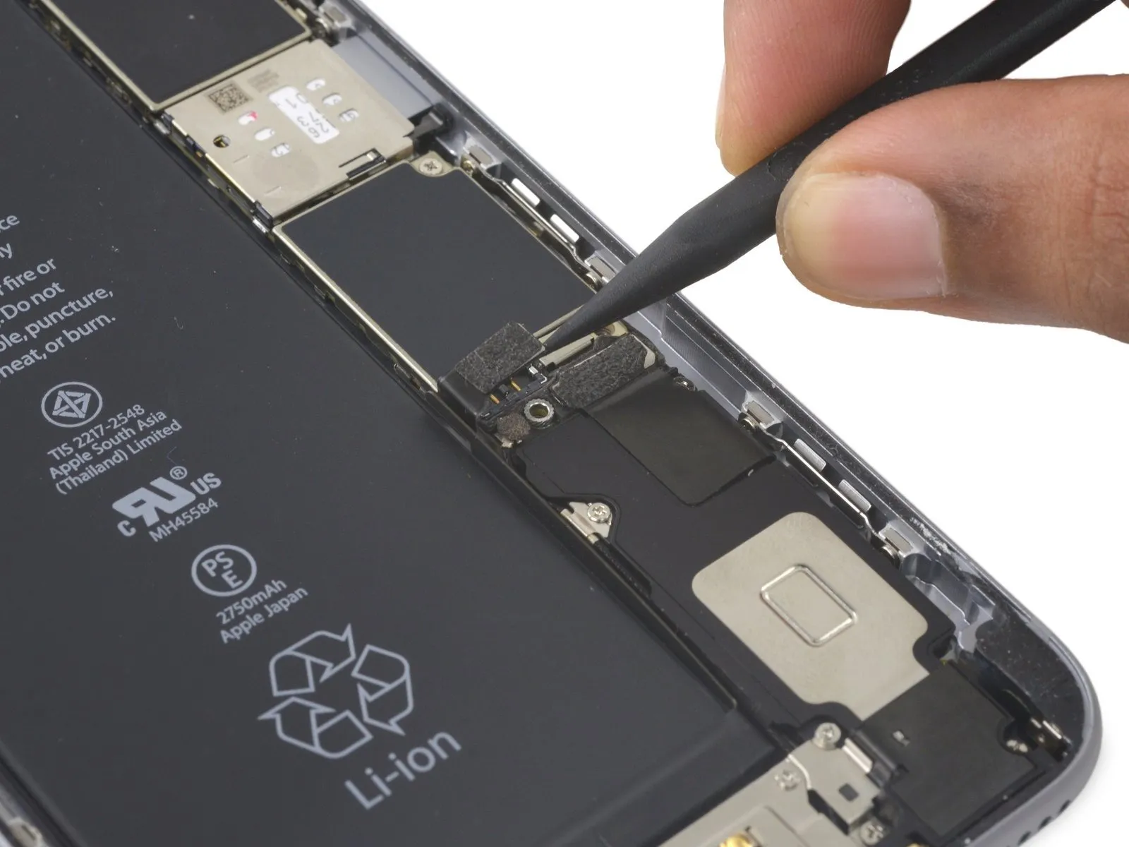
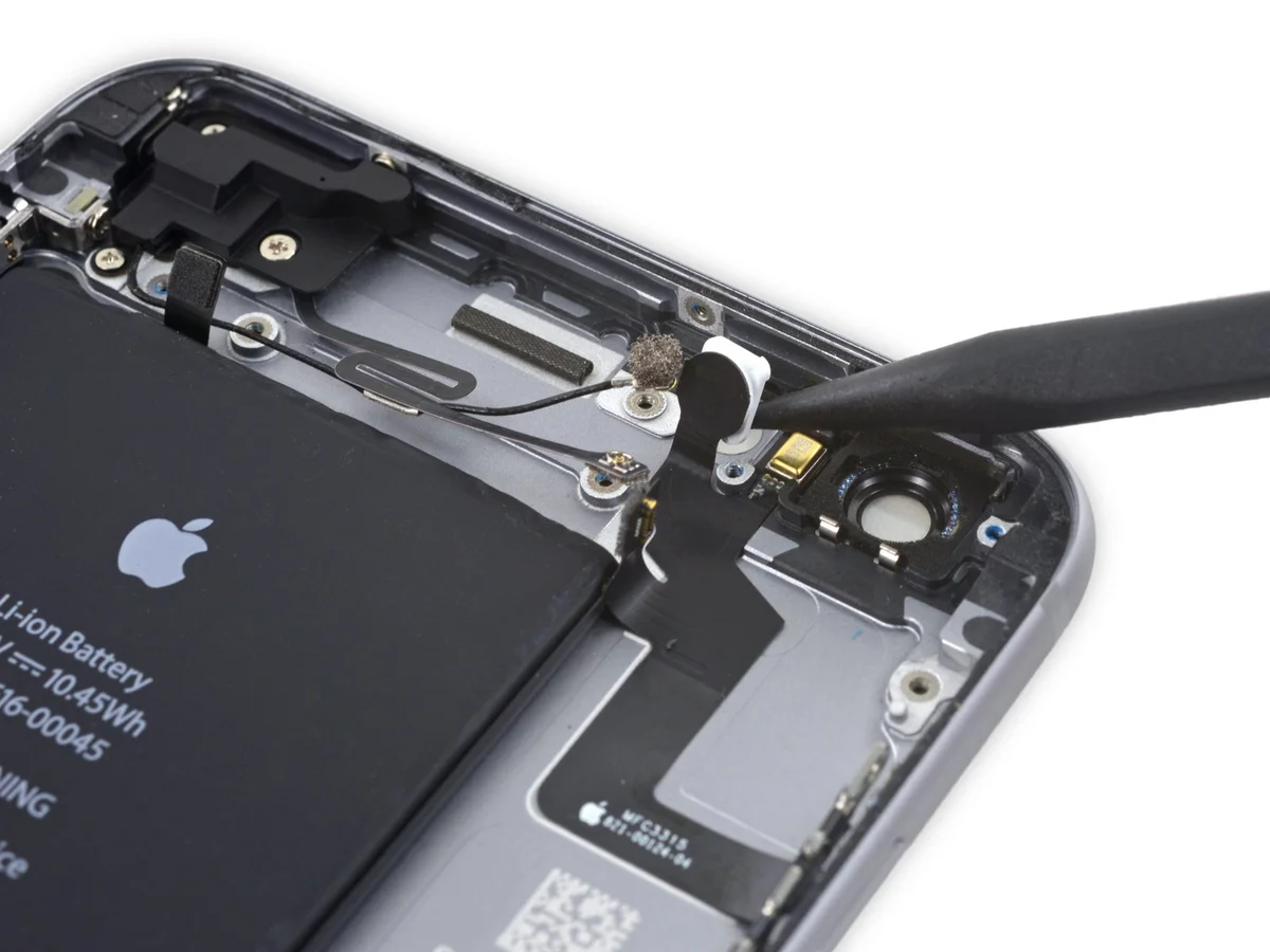
Step 38
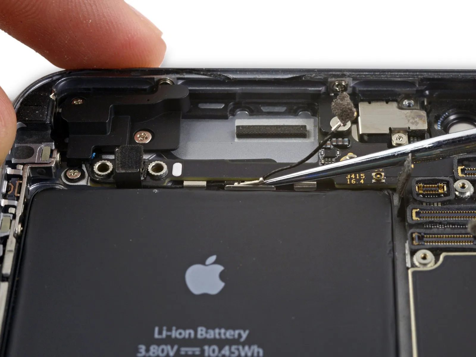
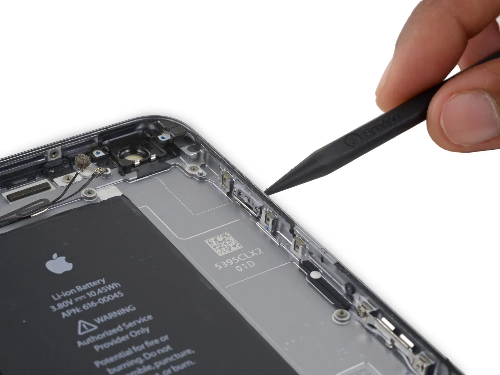
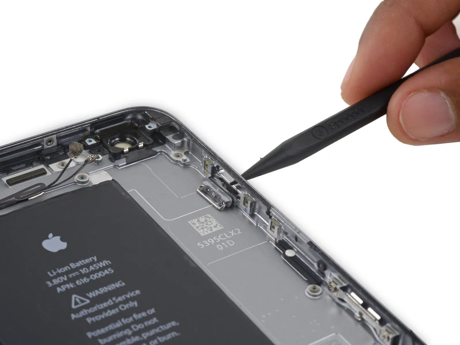
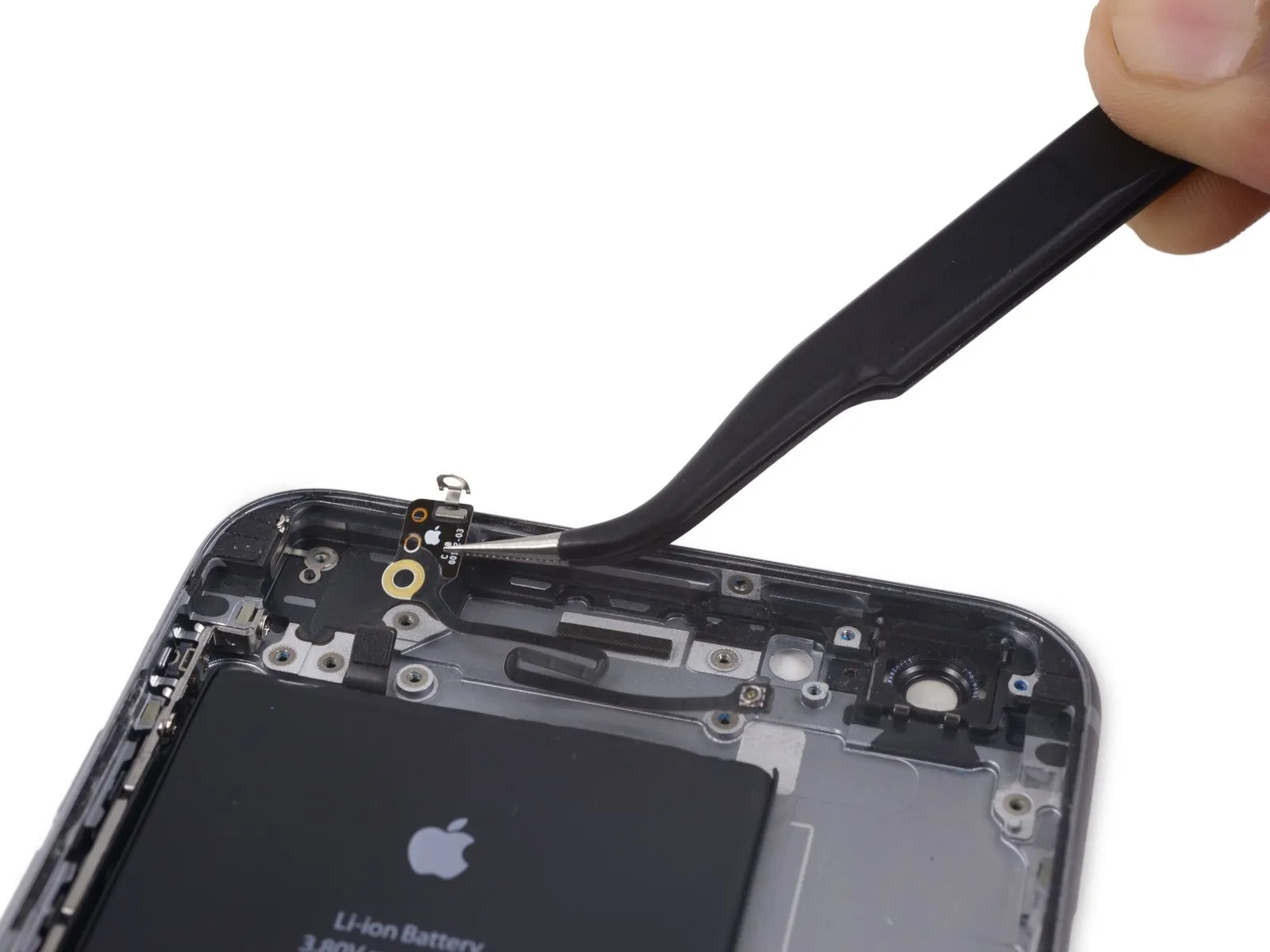
- To detach thecellular antenna cablerelease its connector from the logic board's socket by applying upward force directly.
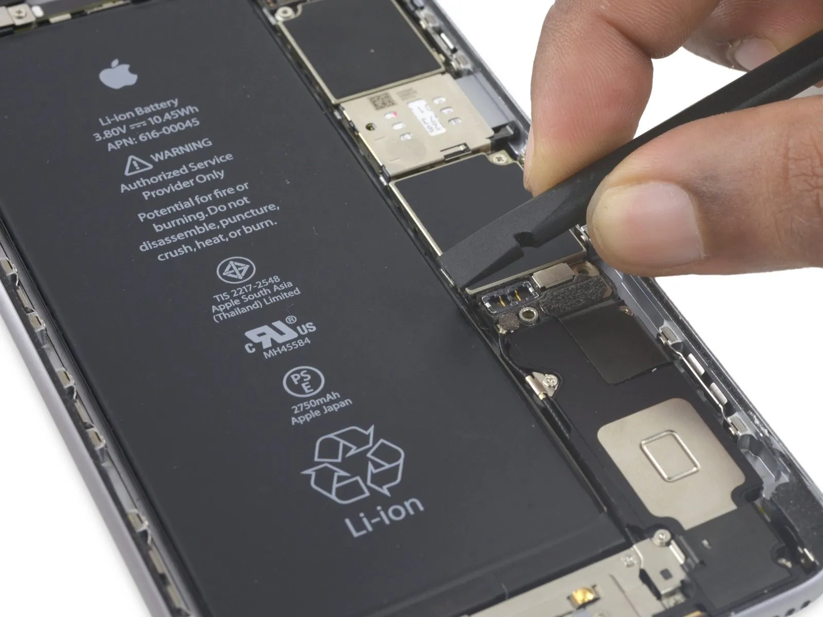
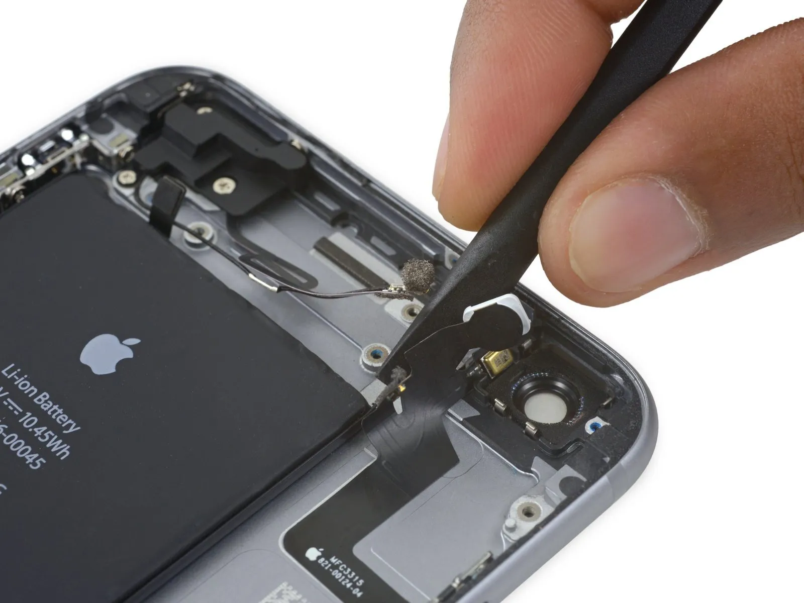
Step 39

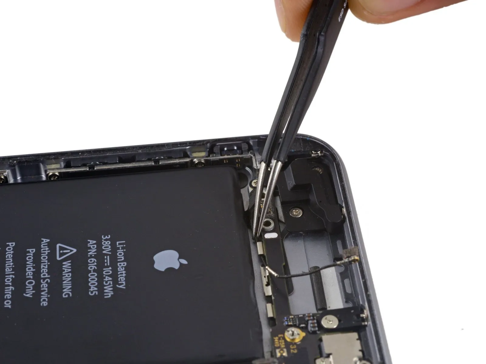
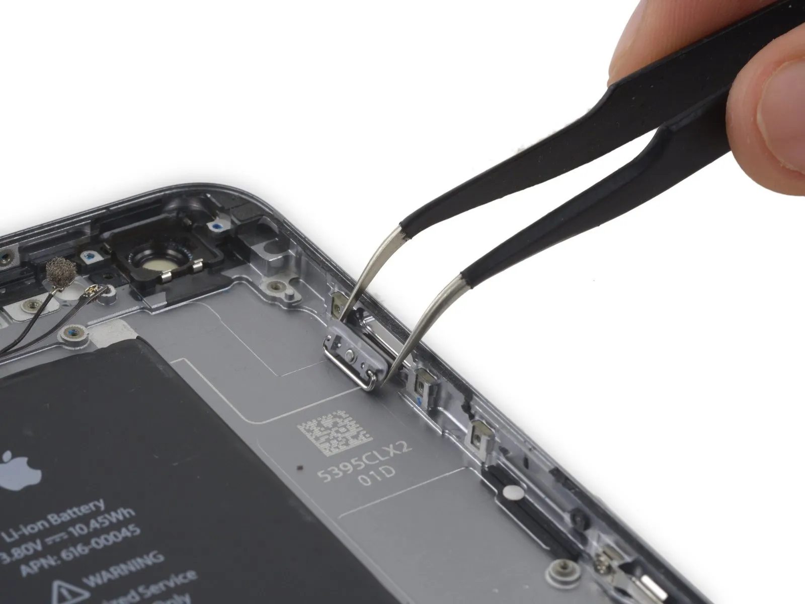
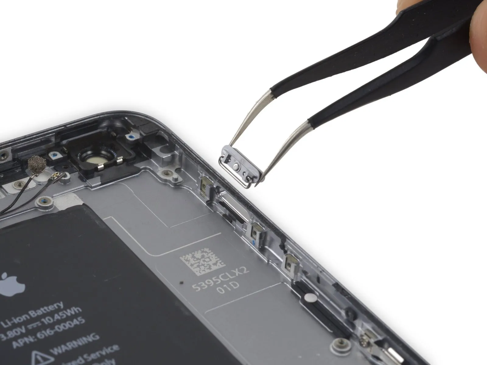
- To detach the Wi-Fi diversity antenna cablerelease its connector from the logic board using a prying motion.
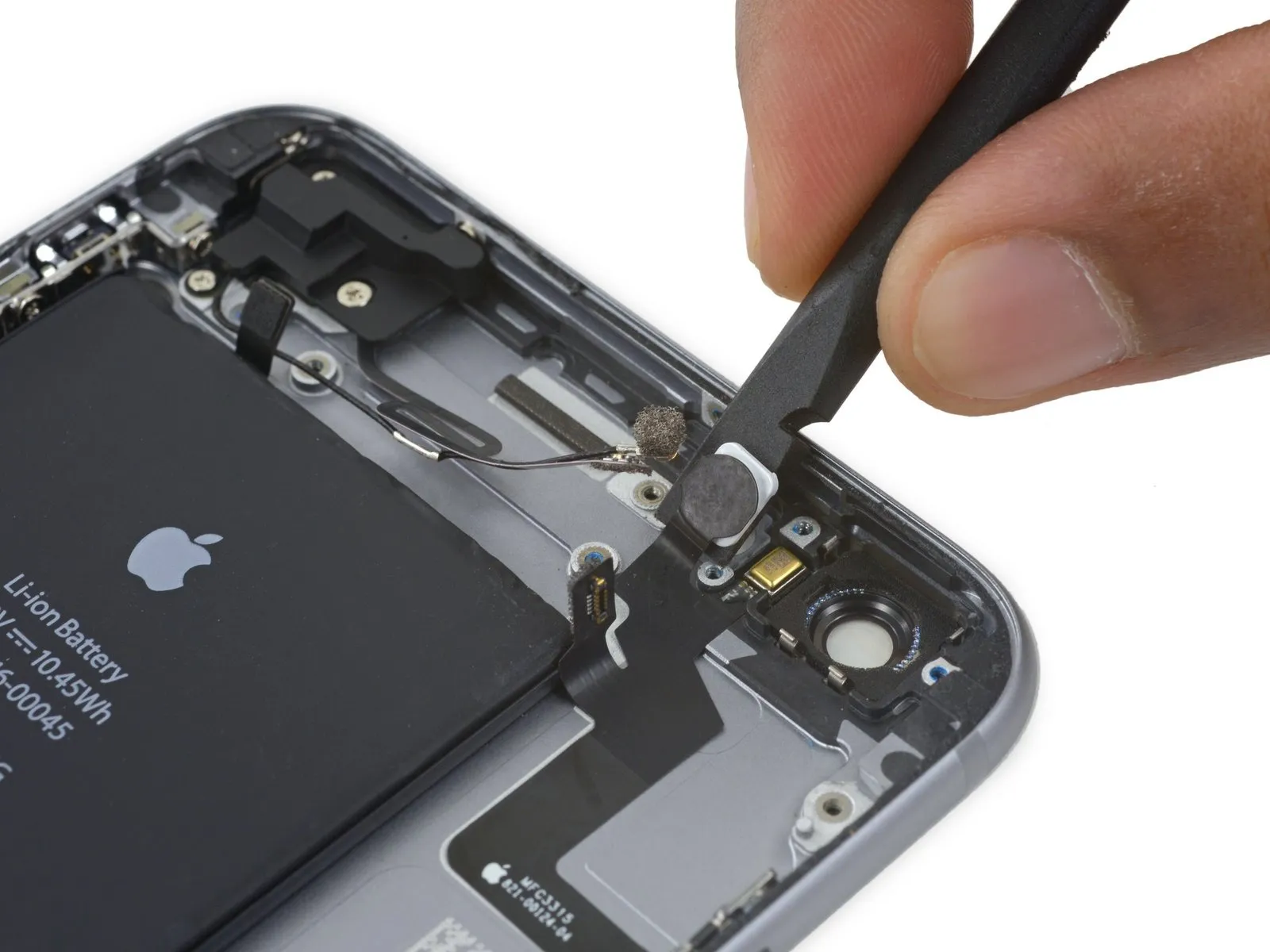
Step 40

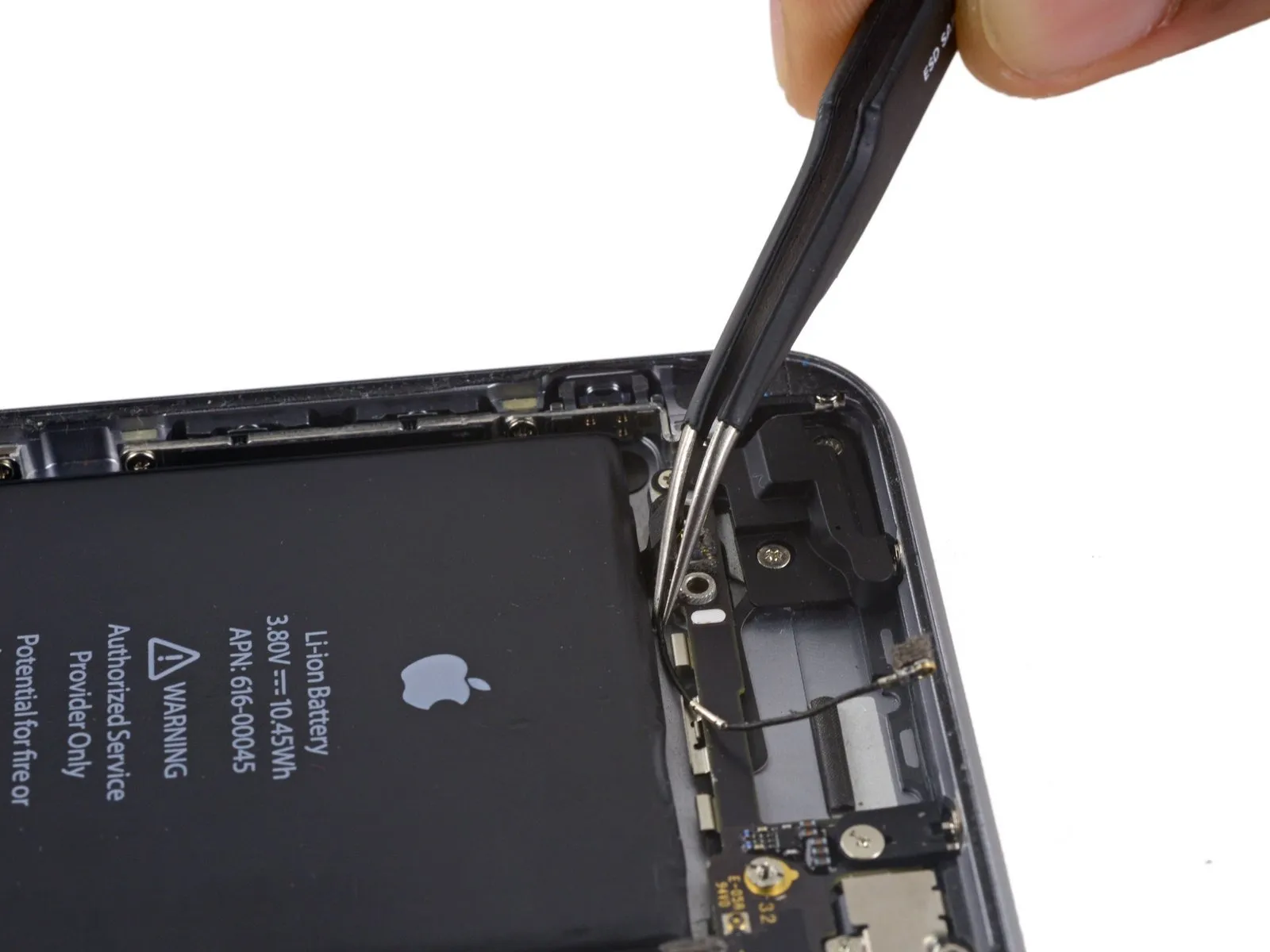
- To proceed, detach thepower button flex cableby carefully separating it from its connector on the main circuit board.
Step 41
Step 42
Step 43

Step 44

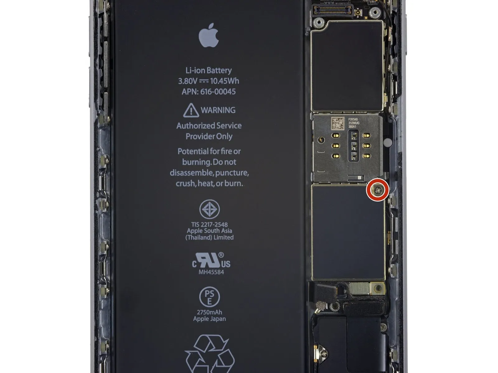
- To disassemble, first detach the listed fasteners:
A Phillips head screw measuring 1.3 millimeters in width must be taken out.
A Phillips head screw with a 2.6-millimeter width also needs to be removed.
A standoff screw, measuring 2.2 millimeters, is another fastener to be detached. - Employing a standoff screwdriver or bit is the preferred method for removing standoff screws.
- If a standoff screwdriver isn't available, a small flathead screwdriver can be used as a substitute; however, exercise heightened care to prevent slippage and potential harm to nearby parts.
Step 45
Step 46
Step 47
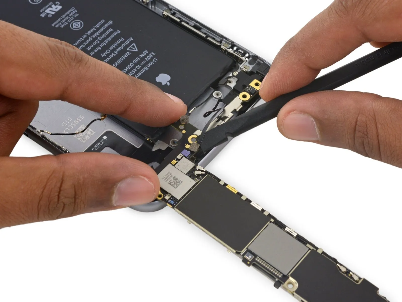
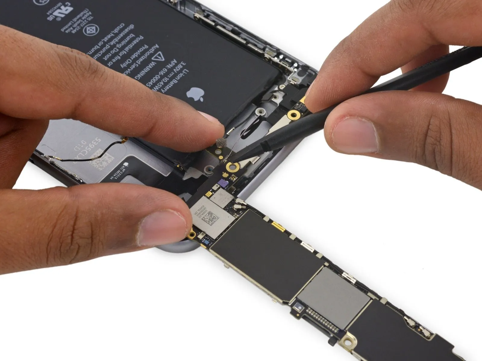
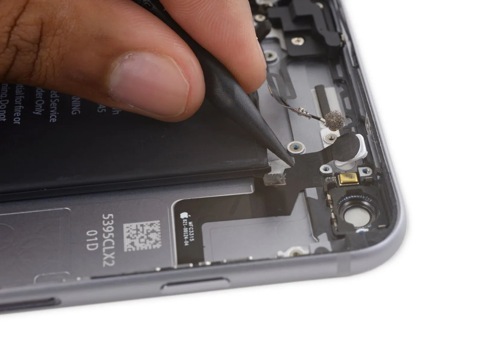
- Proceed with disconnecting the cellular antenna cable from the second and third clips securing it to the logic board.
- Employ the tapered end of a spudgerto carefully separate the cellular antenna cable from the central logic board clip.
- Avoid attempting removal by directly grasping and pulling the cable, because doing so risks damage to the cable's structure.
- To allow the cable to connect to its socket on the logic board, it must be directed over the logic board and beneath the audio control flex cable, referencing the visual guide in the initial photograph for proper placement.
Step 48
Step 49


Step 50
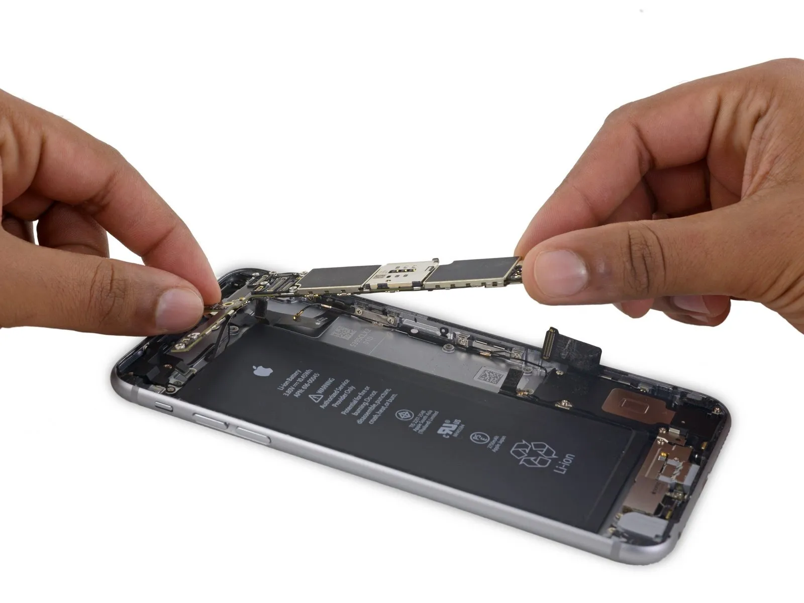
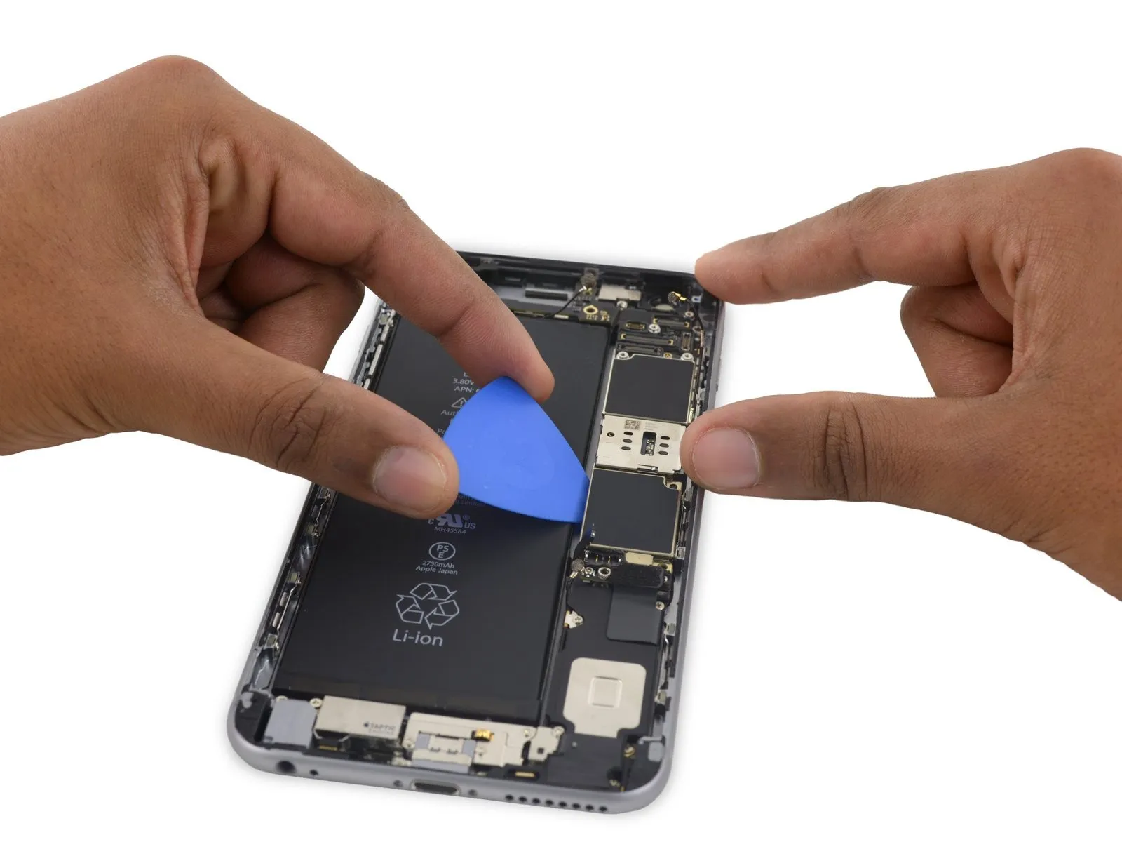
- To reveal the solitary antenna connector situated on the lower surface, close to the upper edge, incline the logic boardinto an upright orientation.
- Refrain from trying to detach the logic boardat this stage, because the Wi-Fi/Bluetooth antenna remains attached to its underside.
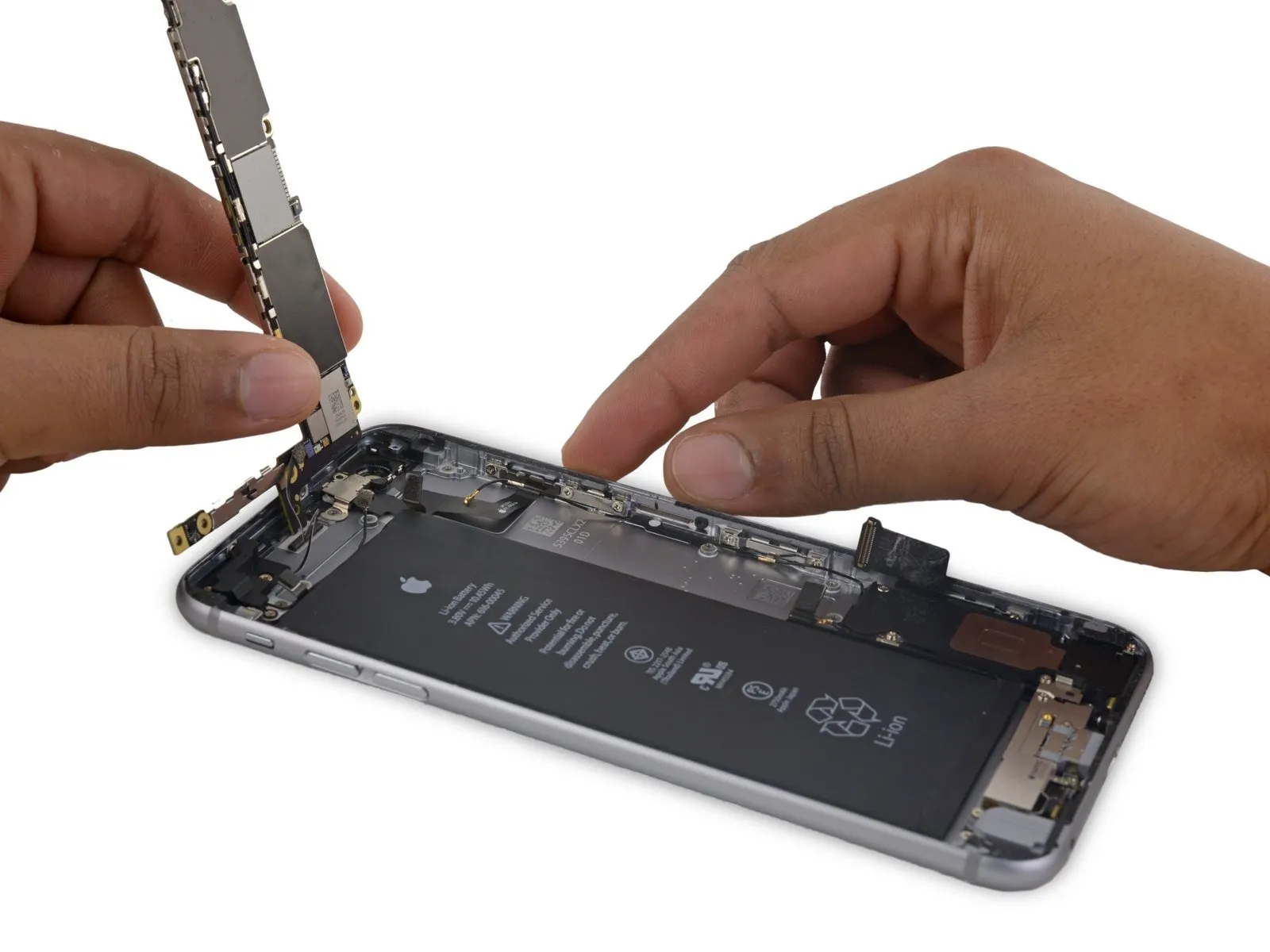
Step 51
- Carefully position the logic boardinverted, ensuring the upper surface makes contact with the iPhone's rear enclosure.
Employ the broad, flat edge of the spudger to release the Wi-Fi/Bluetooth antenna cable from its connector located on the rear side of the logic board.
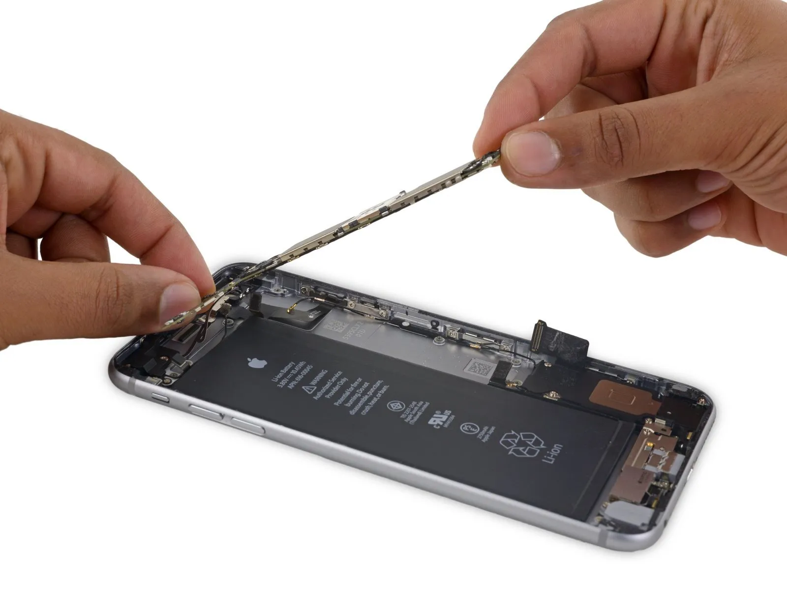
Step 52

- Carefully detach themain circuit boardfrom the device.
Step 53 | Speaker Assembly


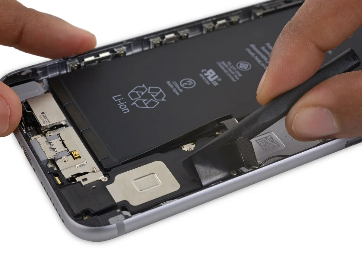
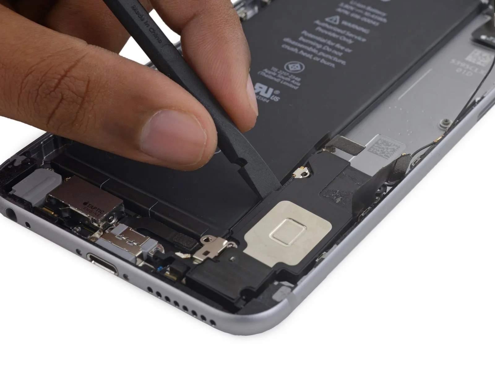
- Employ the planar edge of aspudgerto carefully separate theLightning connector flex cablefrom the speaker assembly.
Step 54
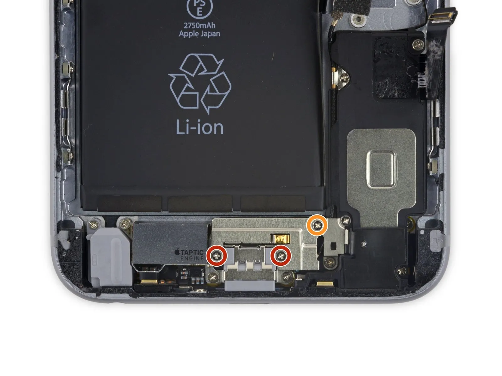
- To proceed, detach these three components:Utilize a Phillips head screwdriver for this step.These screws secure the Taptic Engine cable bracket.
- Specifically, you will encounter twofasteners with a diameter of 3.5 millimeters.
- Additionally, a singlefastener measuring 2.7 millimeters in diameter is present.
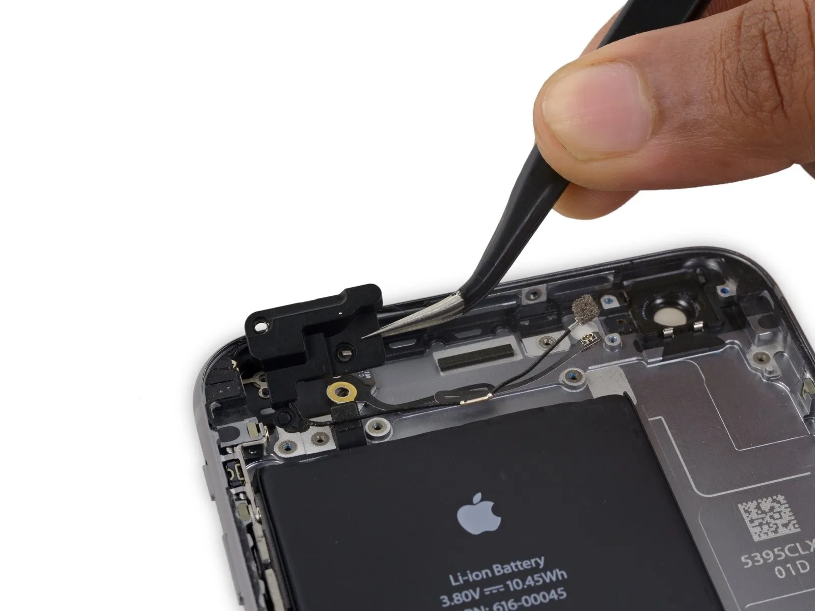
Step 55
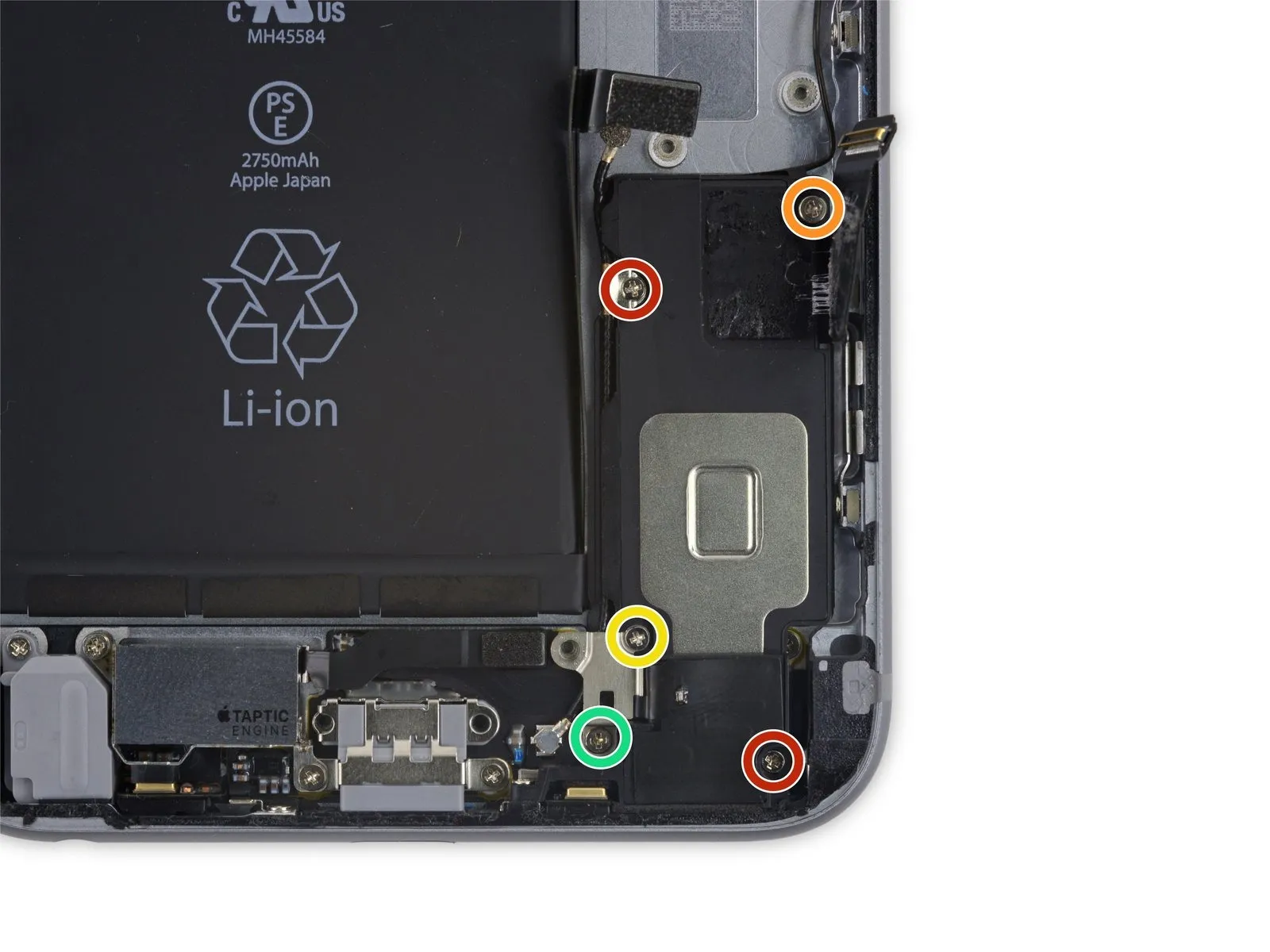
- To detach the speaker, begin by eliminating the five fasteners that hold it in place on the rear case.These fasteners consist of Phillips head screws.The speaker is affixed to the rear case using these screws.
- Among these screws are two with a diameter of 2.7 millimeters.Additionally, a single screw measures 2.5 millimeters in diameter.
- A further screw has a diameter of 1.5 millimeters.Also present is a screw with a diameter of 1.7 millimeters.
- The speaker's attachment relies on the combined function of these five screws.Carefully remove each screw, noting their individual sizes.
- Ensure all screws are accounted for to prevent loss during the repair process.The specified screw sizes are critical for proper reassembly.
Step 56

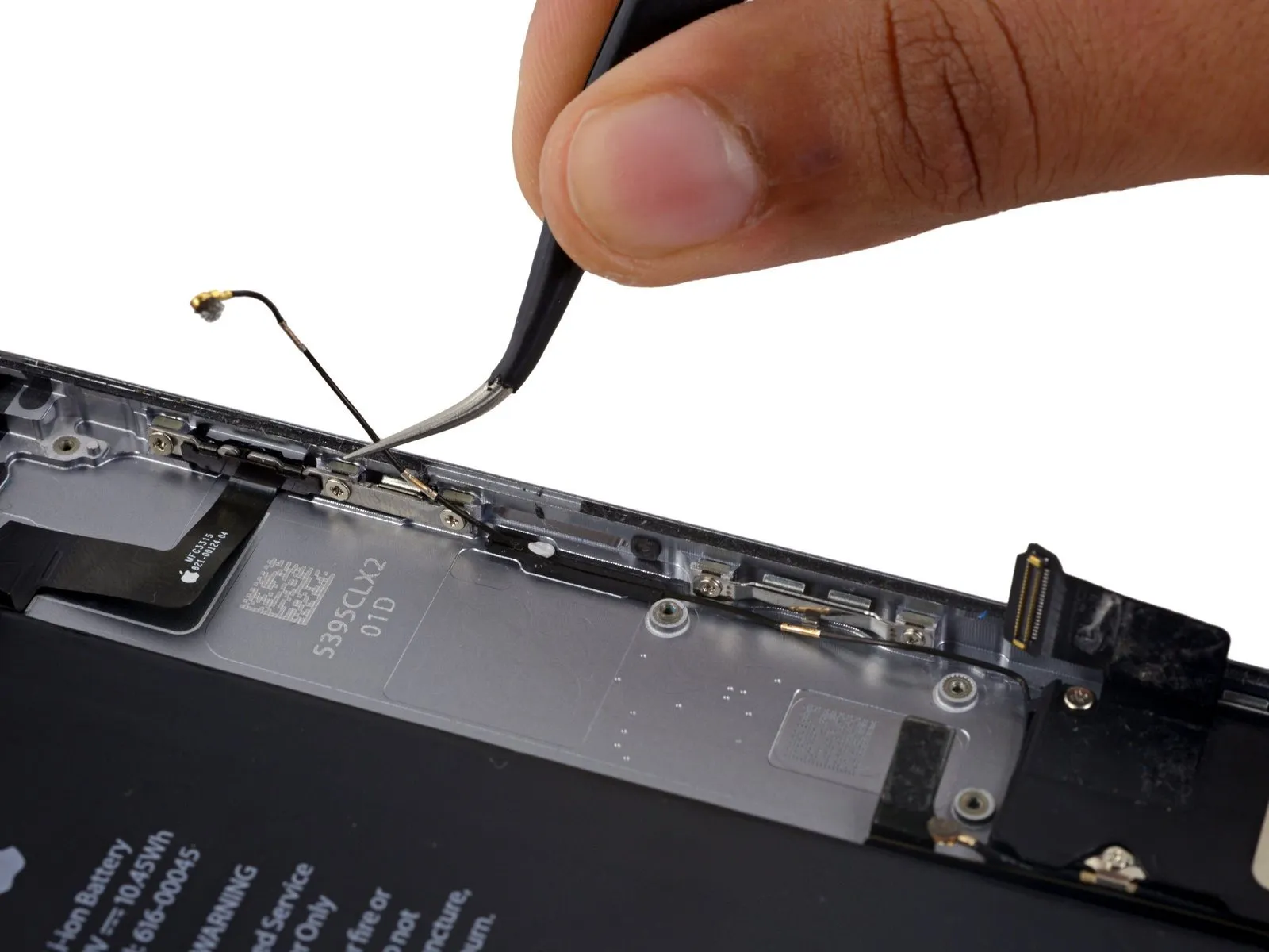
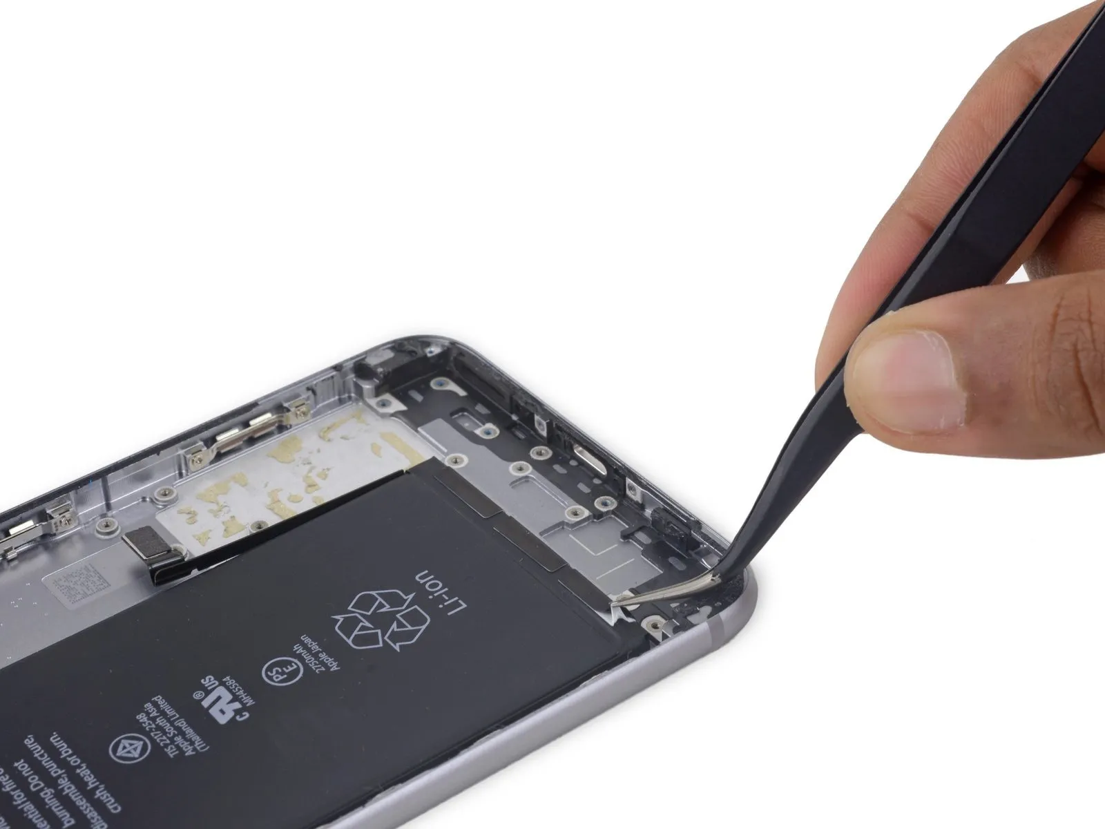
- Disconnect the Wi-Fi diversity antenna cable from its protective rubber sleeve.
Should the white water damage indicator sticker obstruct access to the antenna cable, carefully lift a portion of the sticker to facilitate easier manipulation.
Step 57
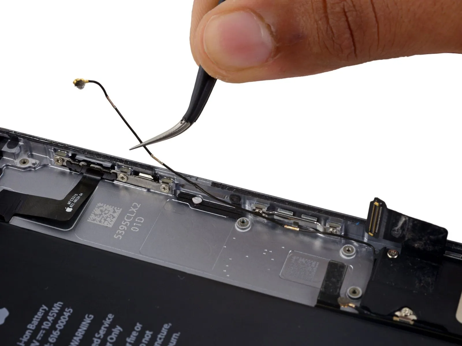
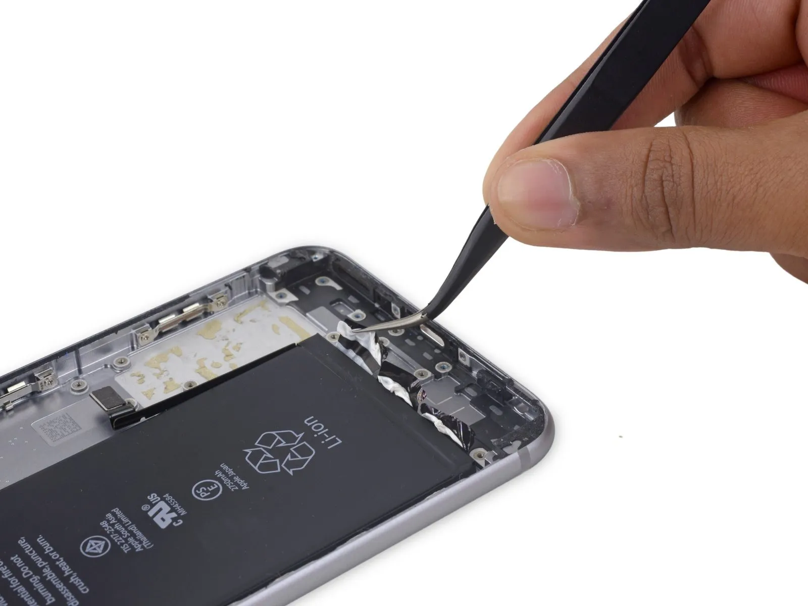
- Employing a set of tweezers, carefully detach the Wi-Fi diversity antenna cable from the Lightning connector flex cable.Utilize tweezers to separate the Wi-Fi diversity antenna cable from the Lightning connector flex cable.A pair of tweezers should be used for the purpose of disconnecting the Wi-Fi diversity antenna cable from the Lightning connector flex cable.
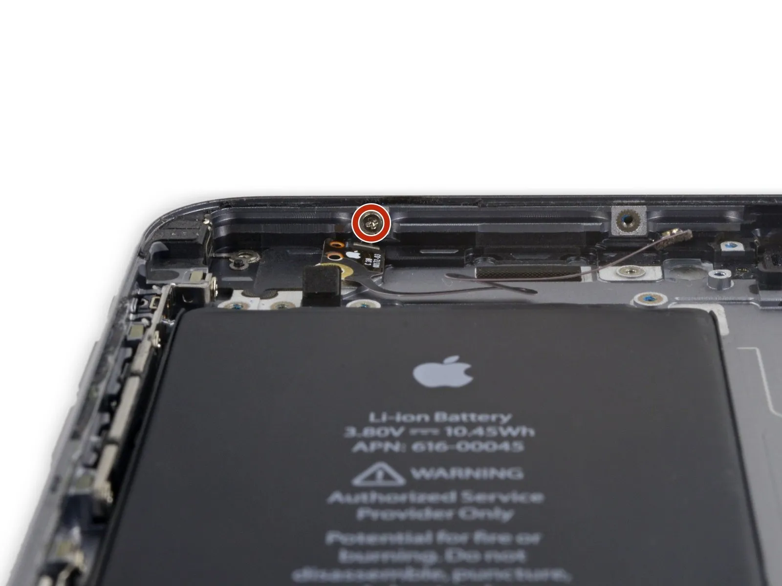
Step 58
- Detach the last screw, measuring 2.6 millimeters in length, which utilizes a Phillips head and holds the speaker in place against the back cover.Phillips screw securing the speaker to the rear case.
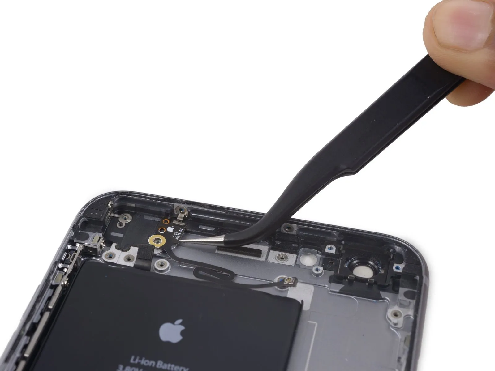
Step 59
- Employ the planar edge of a spudger tool to disengage the speaker assembly from its retaining structure.
- Detach the speaker assembly from its location.
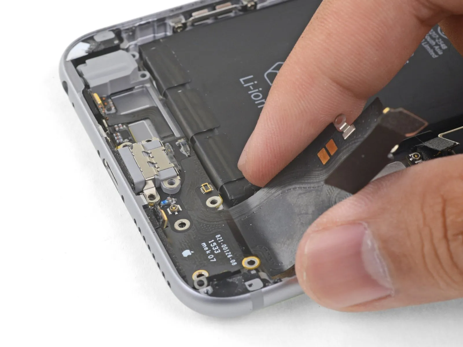
Step 60 | Lightning Connector and Headphone Jack

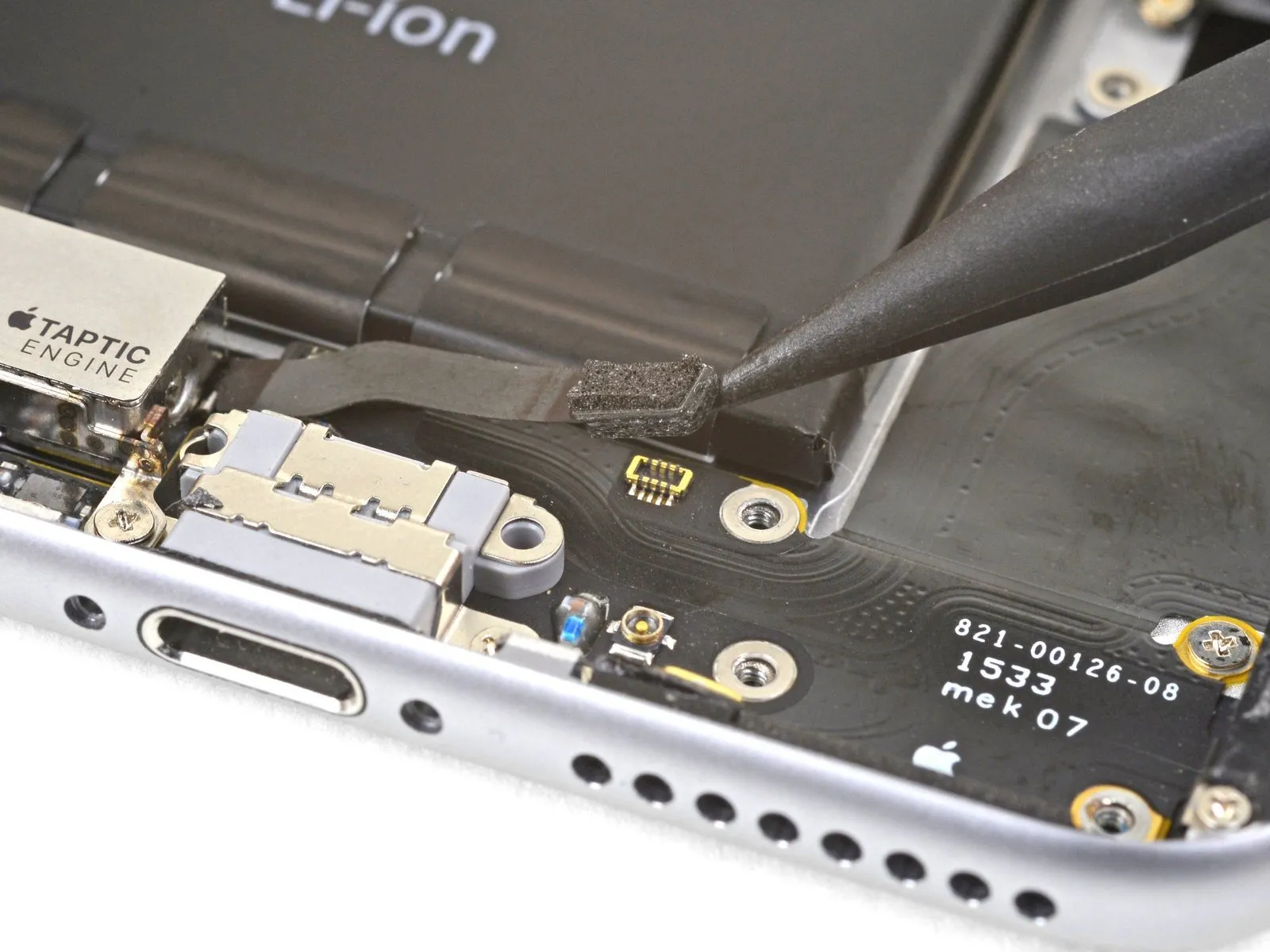
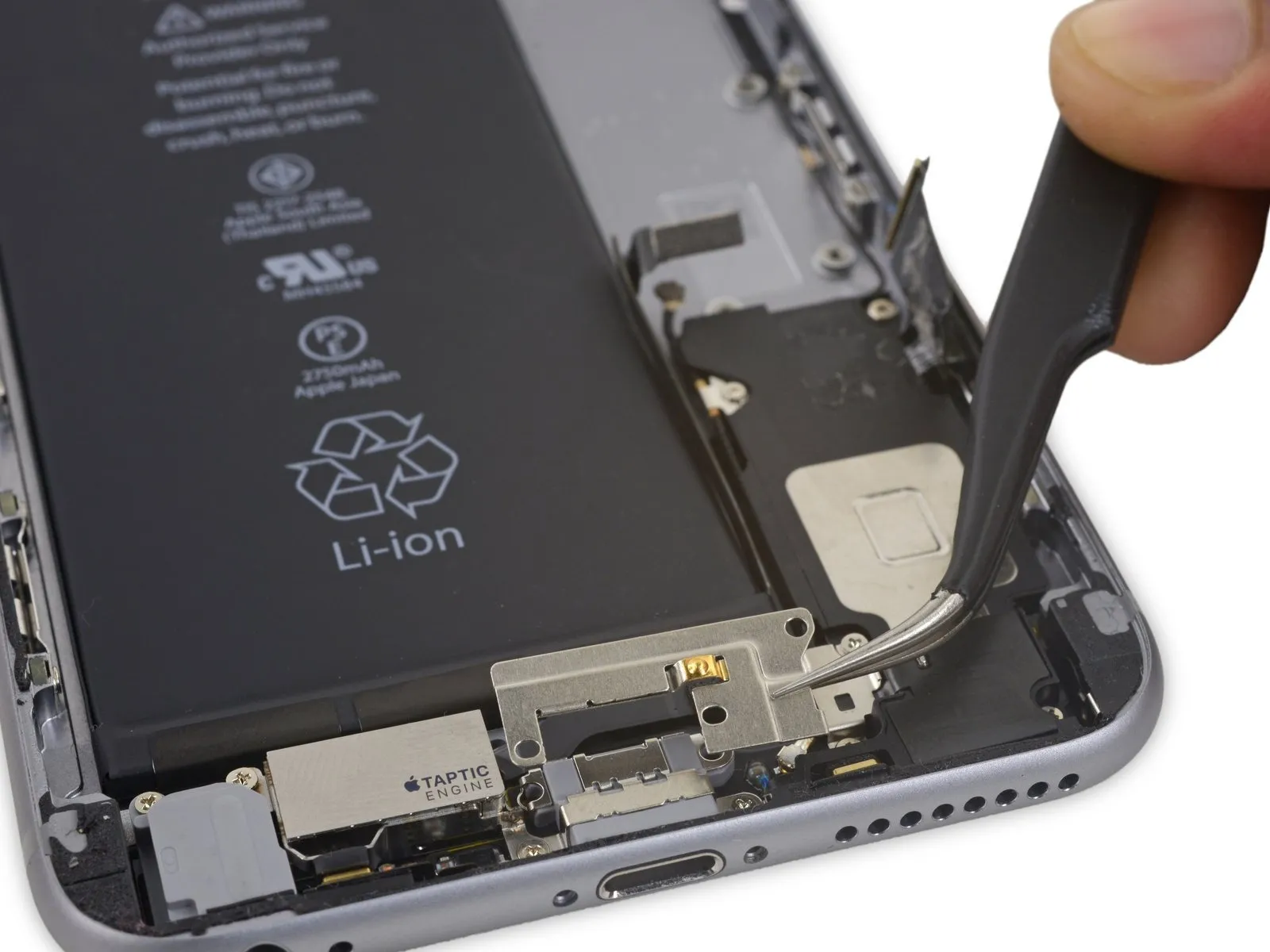
- Carefully leverage the tip of a spudger to separate the Taptic Engine flex cable connector from the lower flex cable assembly.
Step 61
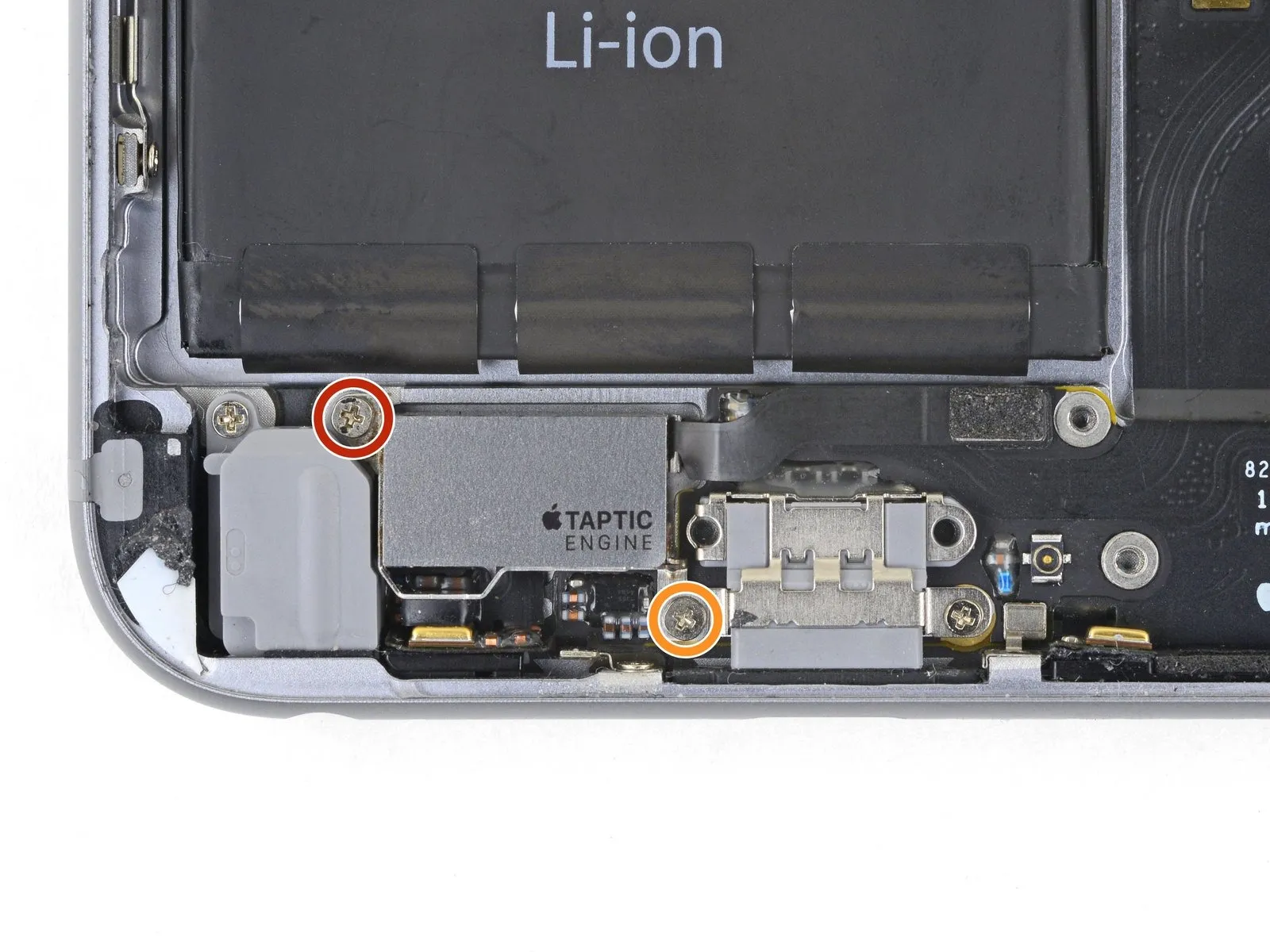

- Detachthe pair ofPhillips-head fastenersthat hold theTaptic Enginein place on the back cover:
A 3.1-millimeter screw
and a 2.1-millimeter screw - DisengagetheTaptic Engine.
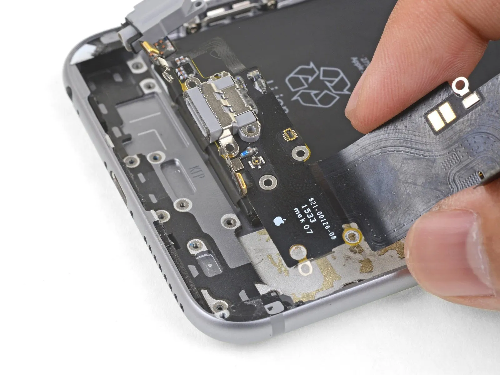
Step 62

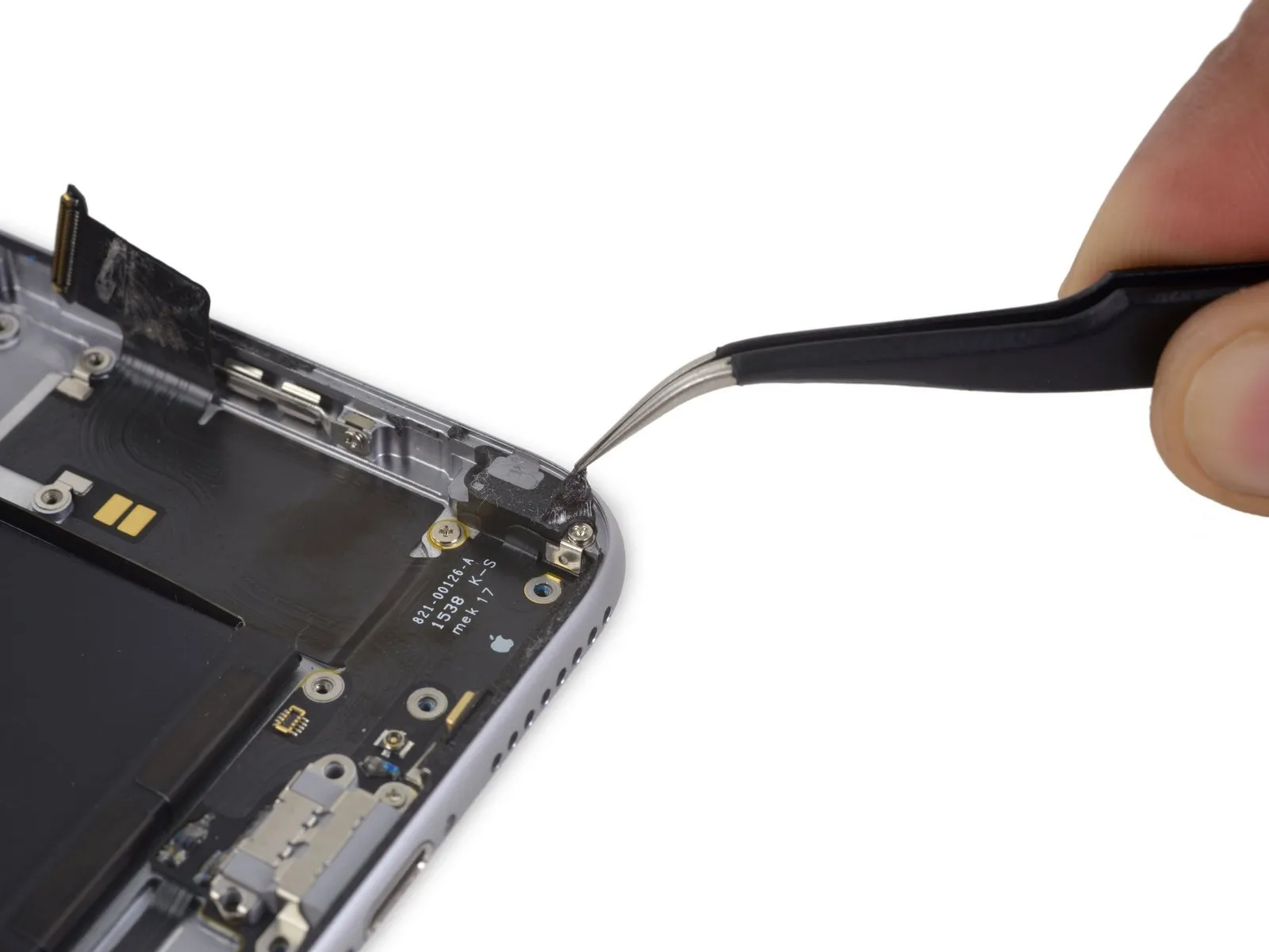
Carefully lift the adhesive strip covering the screw that holds the Lightning connector flex cable in place on the phone's edge.The screw secures the Lightning connector flex cable to the phone's lip.
Step 63

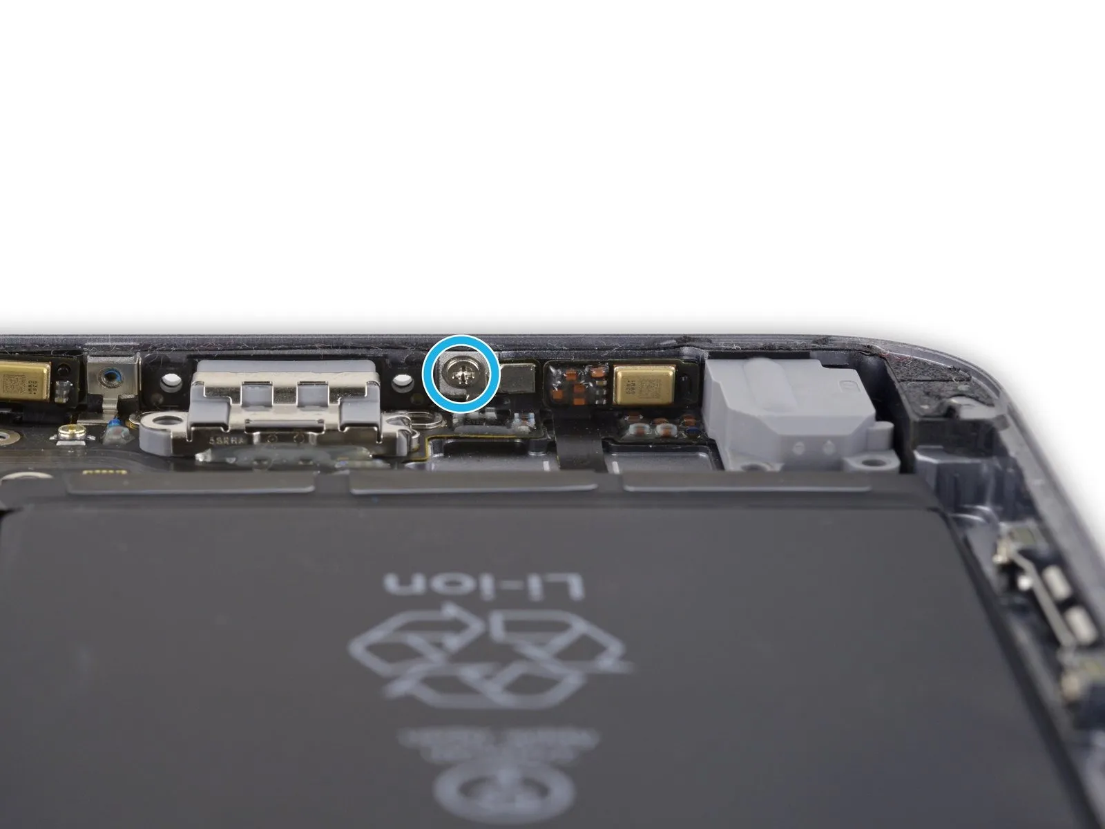
- Detachthese particular fivePhillips head fastenersas follows:
A 2.9-millimeter screw
A 1.9-millimeter screw
A 1.5-millimeter screw
A 1.6-millimeter screw
A 1.3-millimeter screw assembly located along the lower border of the rear casing
Step 64
Acquire an iOpener device for the upcoming procedure.Position the iOpener along the lower edge of the device to reduce the bonding strength of the adhesive securing the Lightning connector flex cable.
Allow approximately sixty seconds to elapse.Give the adhesive sufficient time to become pliable before lifting the iOpener and proceeding with the repair.
Step 65


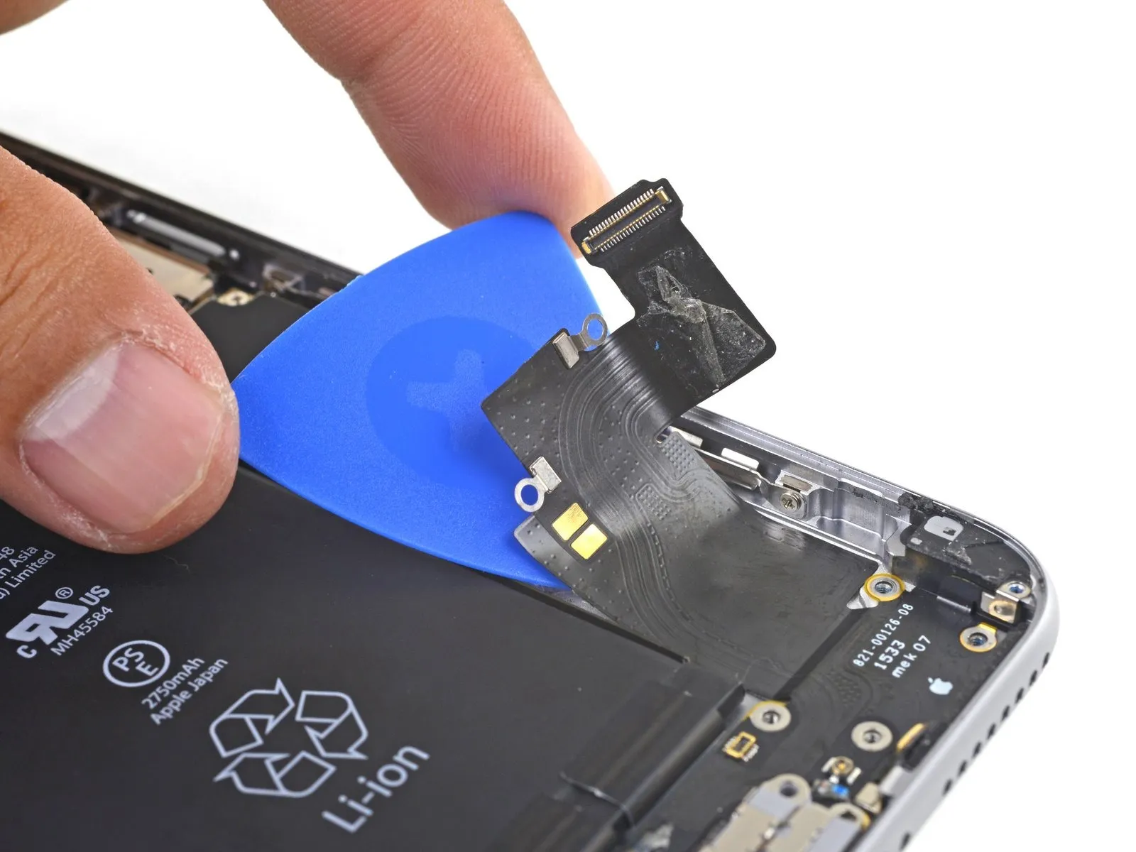
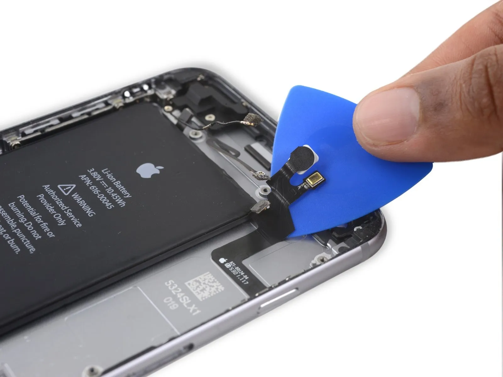
- Carefully slide a specialized opening tool beneath the Lightning connector flex cable, then gently separate the cable from the rear case by severing the adhesive bond.
Step 66


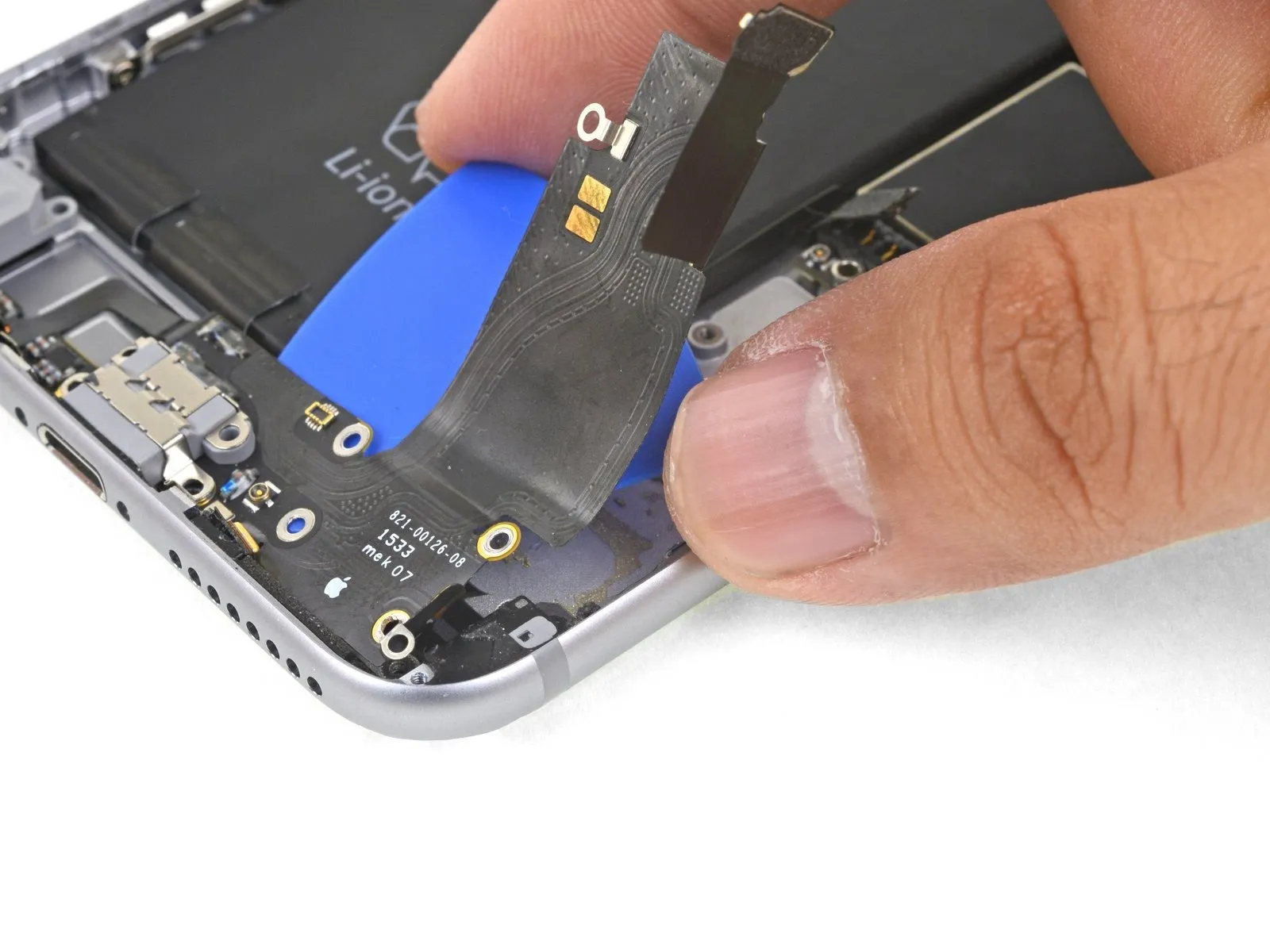
- Proceed to advance the opening tool further beneath the flexible cable.
Step 67
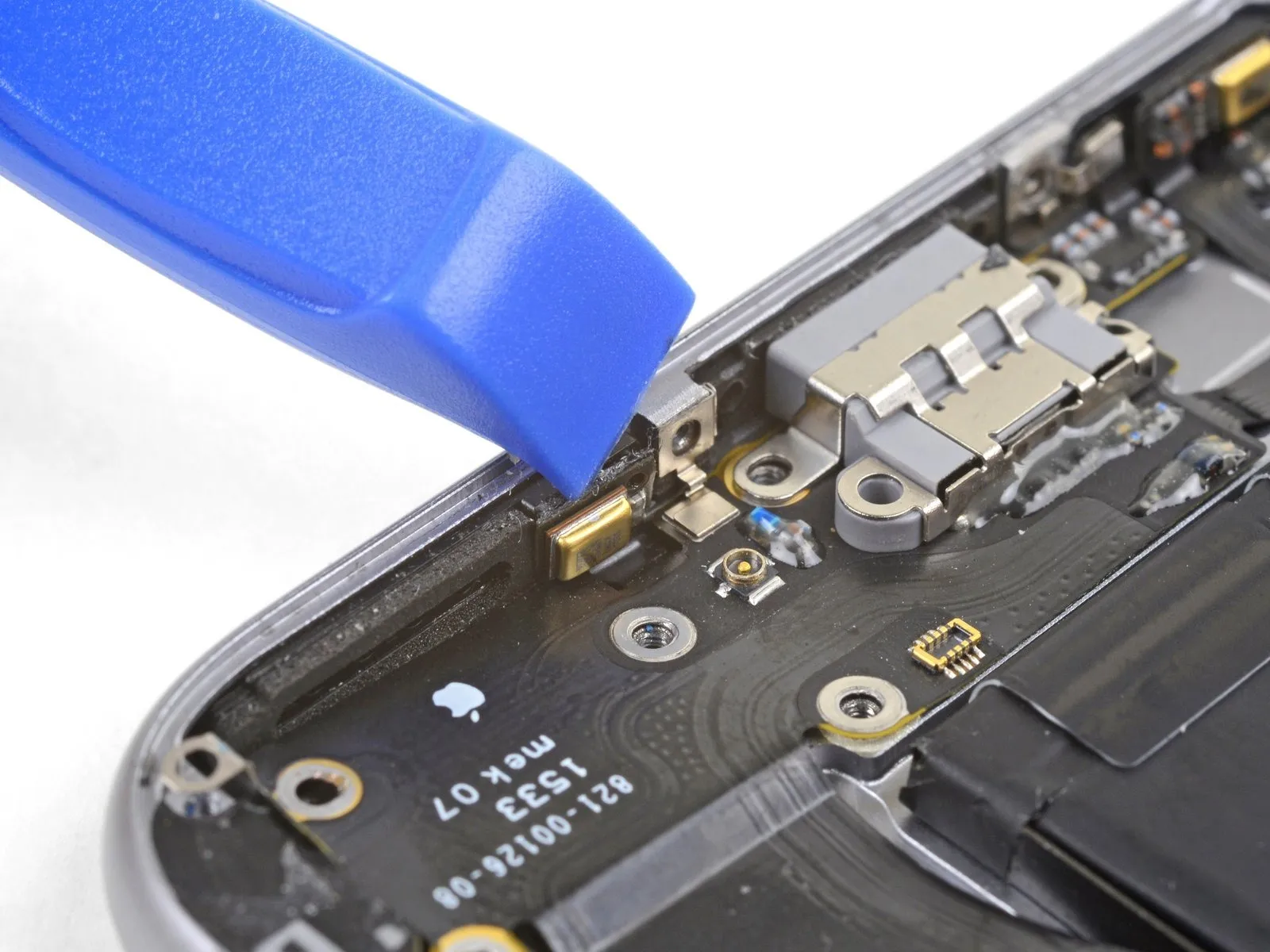


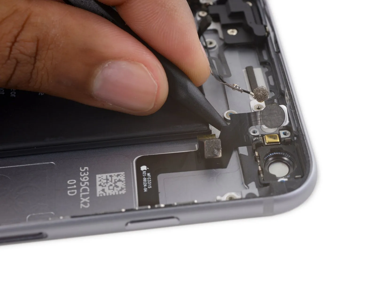
- Carefully disengage the left microphone assembly from the rear case's perimeter using a prying tool.
Step 68
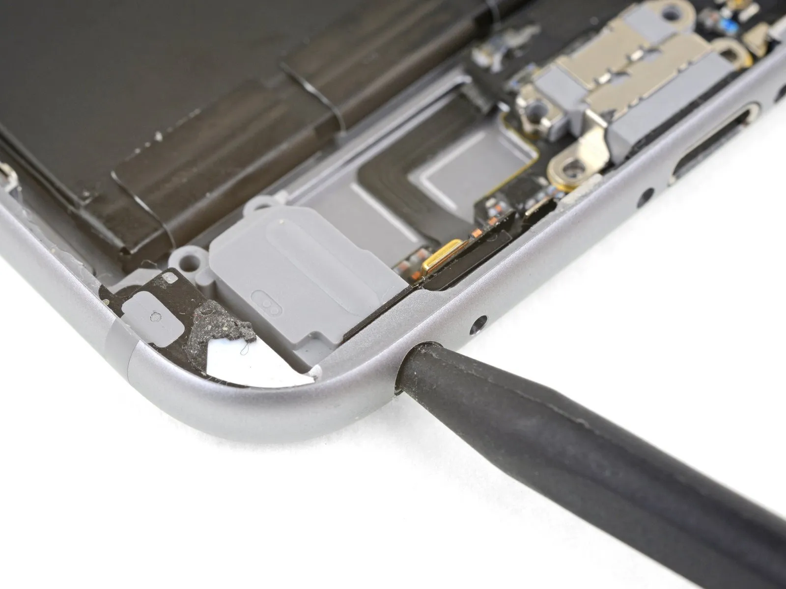
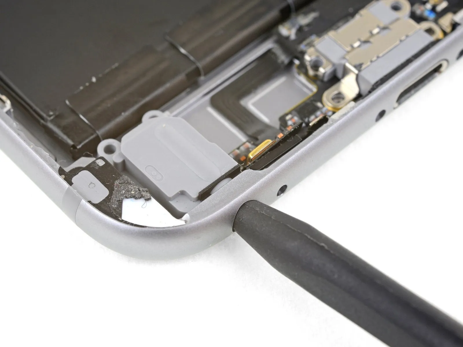
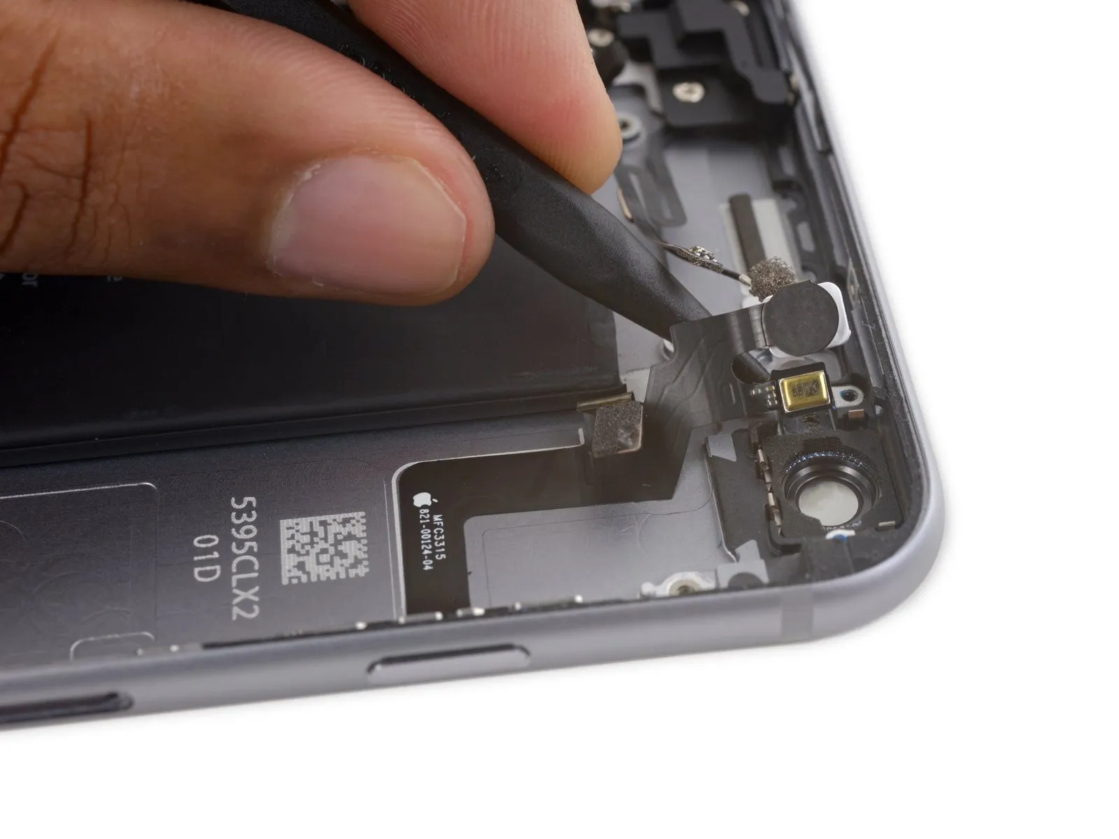
- To detach the headphone jack from the lower case edge, gently manipulate it using a spudger inserted into the jack's opening.
Step 69
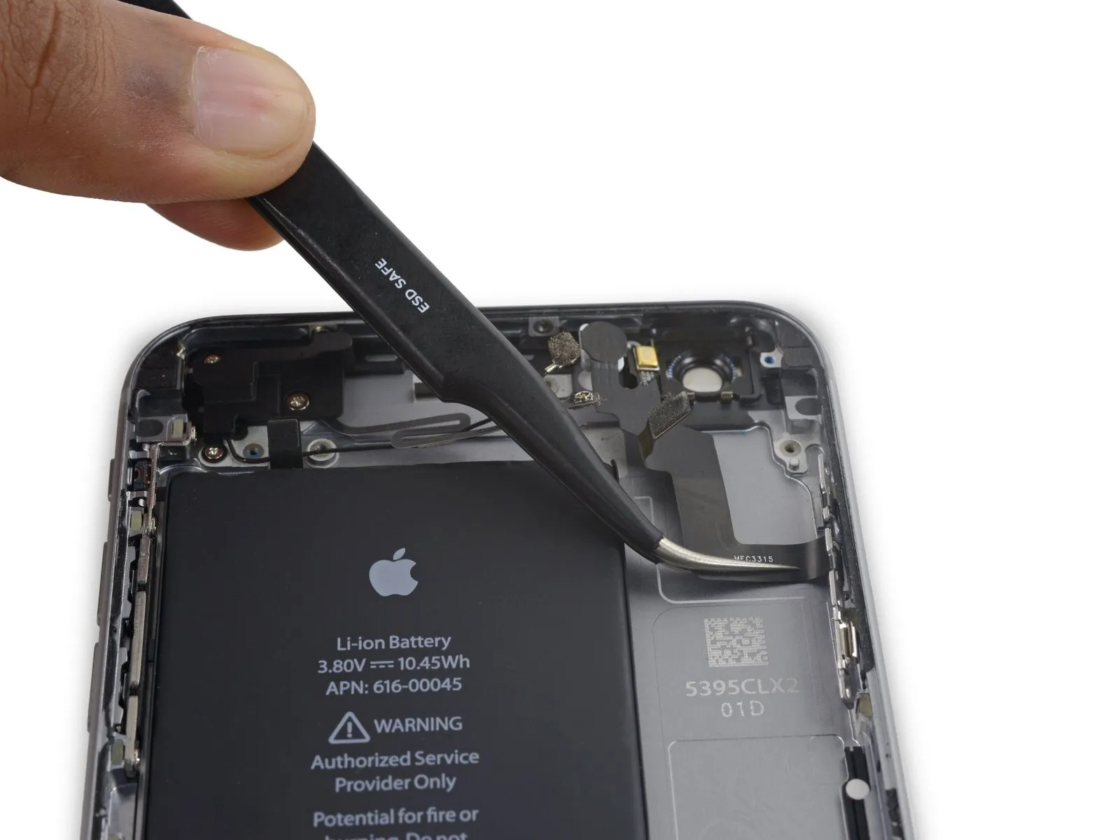
- Detach the Lightning connector assembly from the device.
- Should your new component lack a headphone jack gasket, carefully extract the gasket from the original part with tweezers and affix it to the replacement.
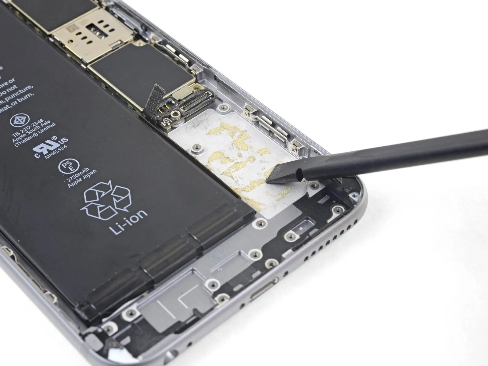
- Prior to reassembly, thoroughly clean any leftover adhesive from the rear case with a spudger; employing a solvent of isopropyl alcohol with a high concentration can aid in this cleaning procedure.
Step 70 | Power Button Cable Assembly

- To proceed with the repair, detach the four Phillips screws listed below.
Specifically, three screws, each measuring 2.0 millimeters in width, secure the power button bracket.These screws are responsible for maintaining the power button bracket's position.
Additionally, a single 1.3-millimeter Phillips screw is located above the flash and microphone bracket.This 1.3 mm Phillips screw provides structural support for the flash and microphone bracket.
Step 71


- Detach theflash/microphone mounting bracket.
Step 72

- Employ the tapered tip of a spudger to carefully disengage the flash component from its securement within the rear case assembly.flash out of its housing in the rear case.
Step 73
- Employ the planar edge of a spudgerto carefully separate the power button flex cable from the rear case's surface.
Step 74
- Carefully slide the pointed end of a spudger between the microphone section of the flex cable and the back cover, applying slight upward pressure to detach it.
Step 75


- Carefully insert a specialized opening tool beneath the flexible cable connected to the power button, utilizing it to detach the cable from the back cover assembly.
Step 76

- Disconnect the power button flex cable assembly from the device.
Step 77 | Power Button Cover
Step 78
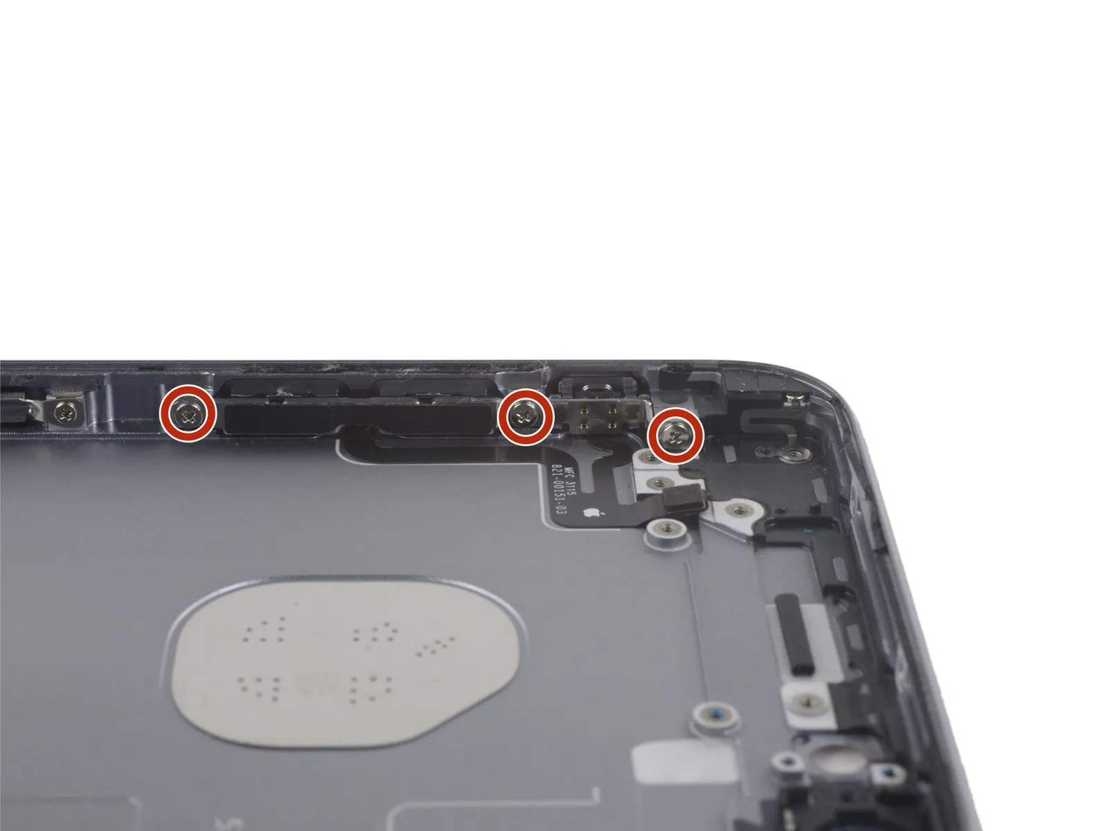
Step 79 | Rear Case
- A single 2.7-millimeter Phillips head screw is required.
- Additionally, utilize one 1.7-millimeter Phillips head screw.
- Furthermore, a single 1.3-millimeter Phillips head screw must be removed.
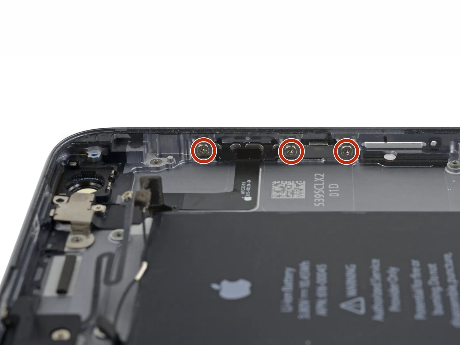
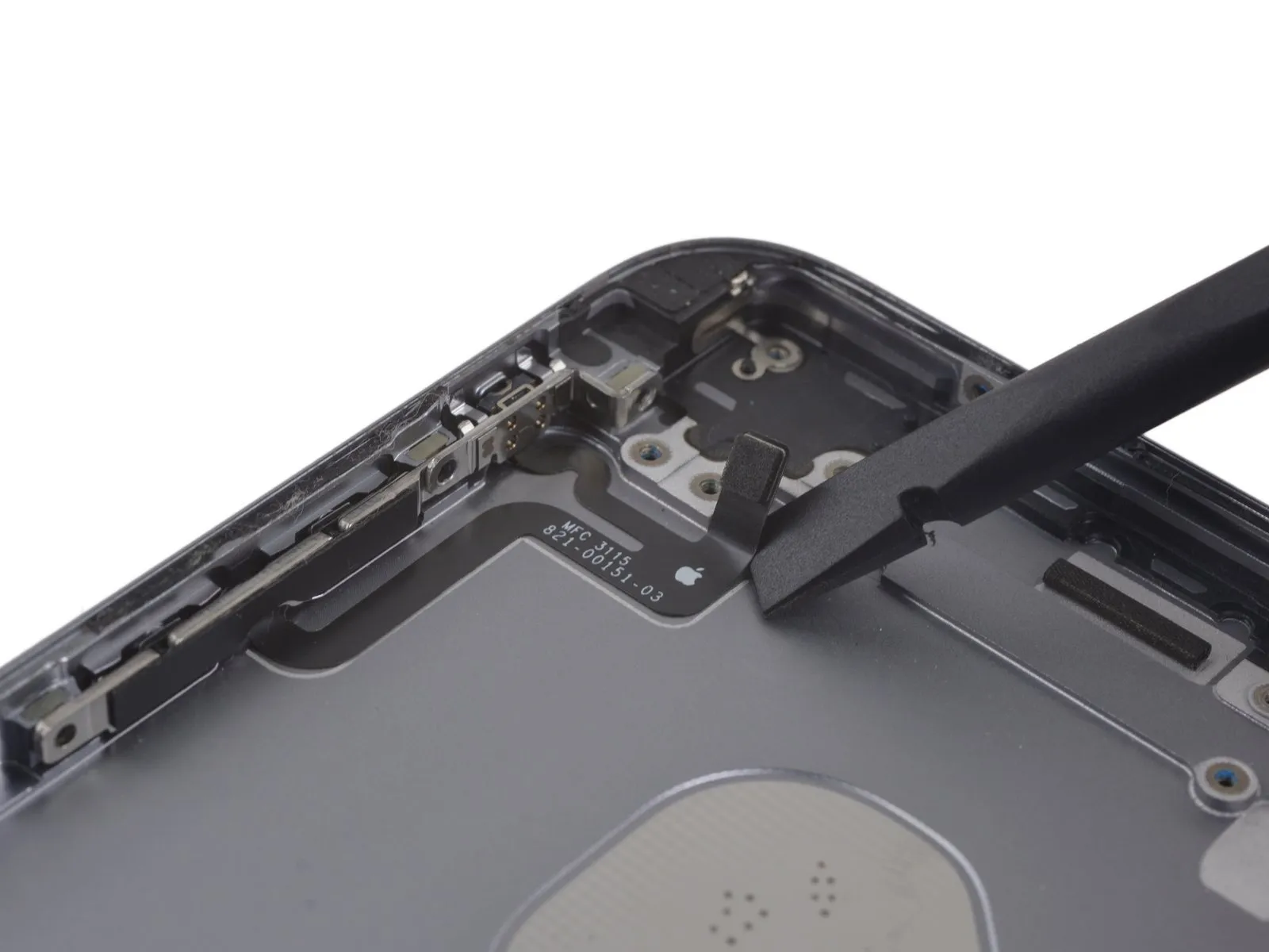
Step 80

Step 81
Detach the solitary 1.3 mm Phillips screw which fastens the Wi-Fi/Bluetooth antenna to the back cover.
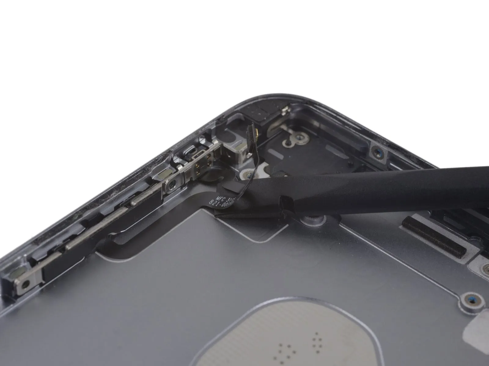
Step 82
Carefully detach the Wi-Fi and Bluetooth antenna assembly.
Step 83

Carefully lift the ends of the three battery adhesive strips situated along the battery's lower border, employing a set of tweezers for precise manipulation.
Step 84
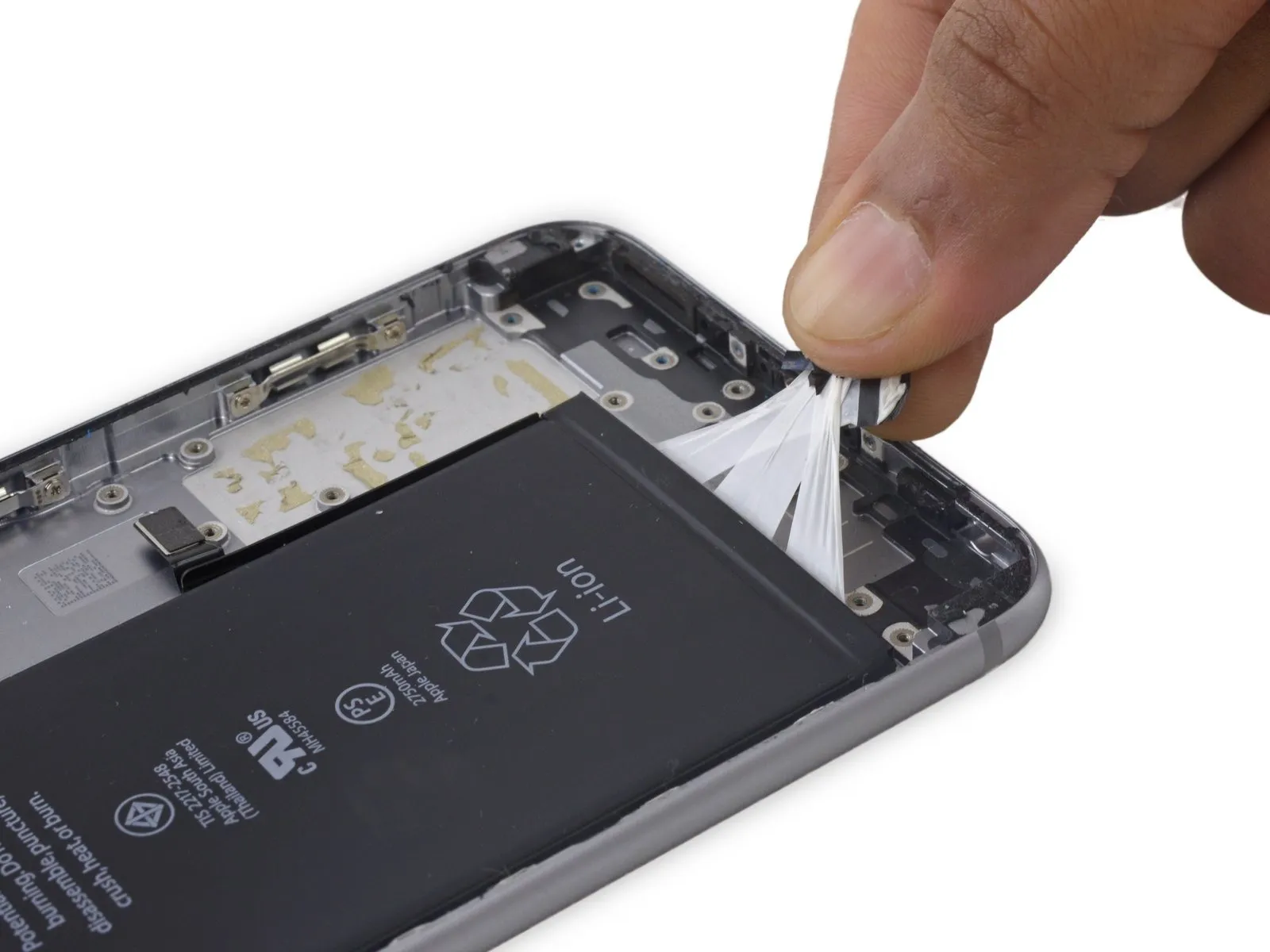
- Collect the three adhesive strip ends from the battery into a single hand.
- Exercise caution to prevent any creases from forming within the strips, as these deformations are irreversible and will complicate subsequent steps.
Step 85
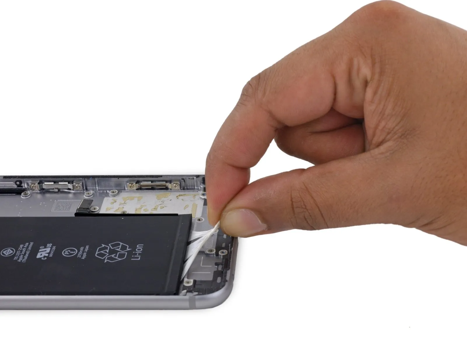
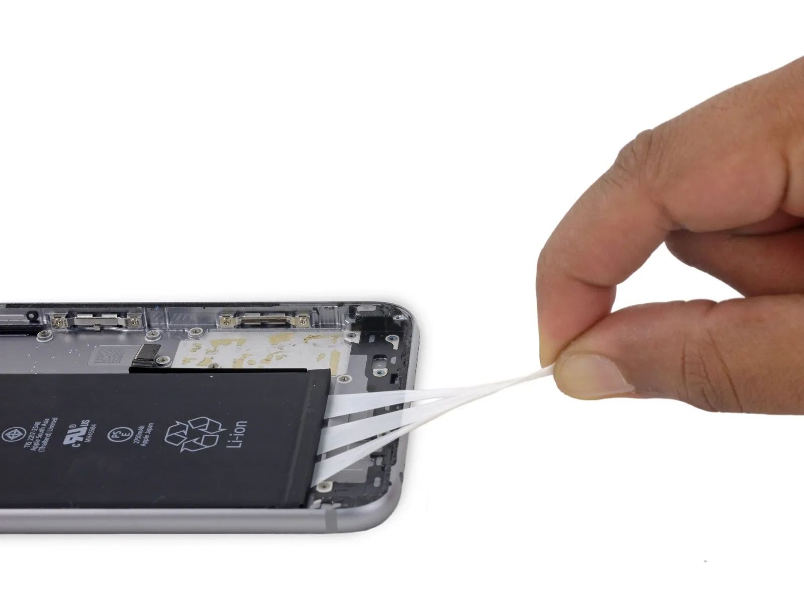
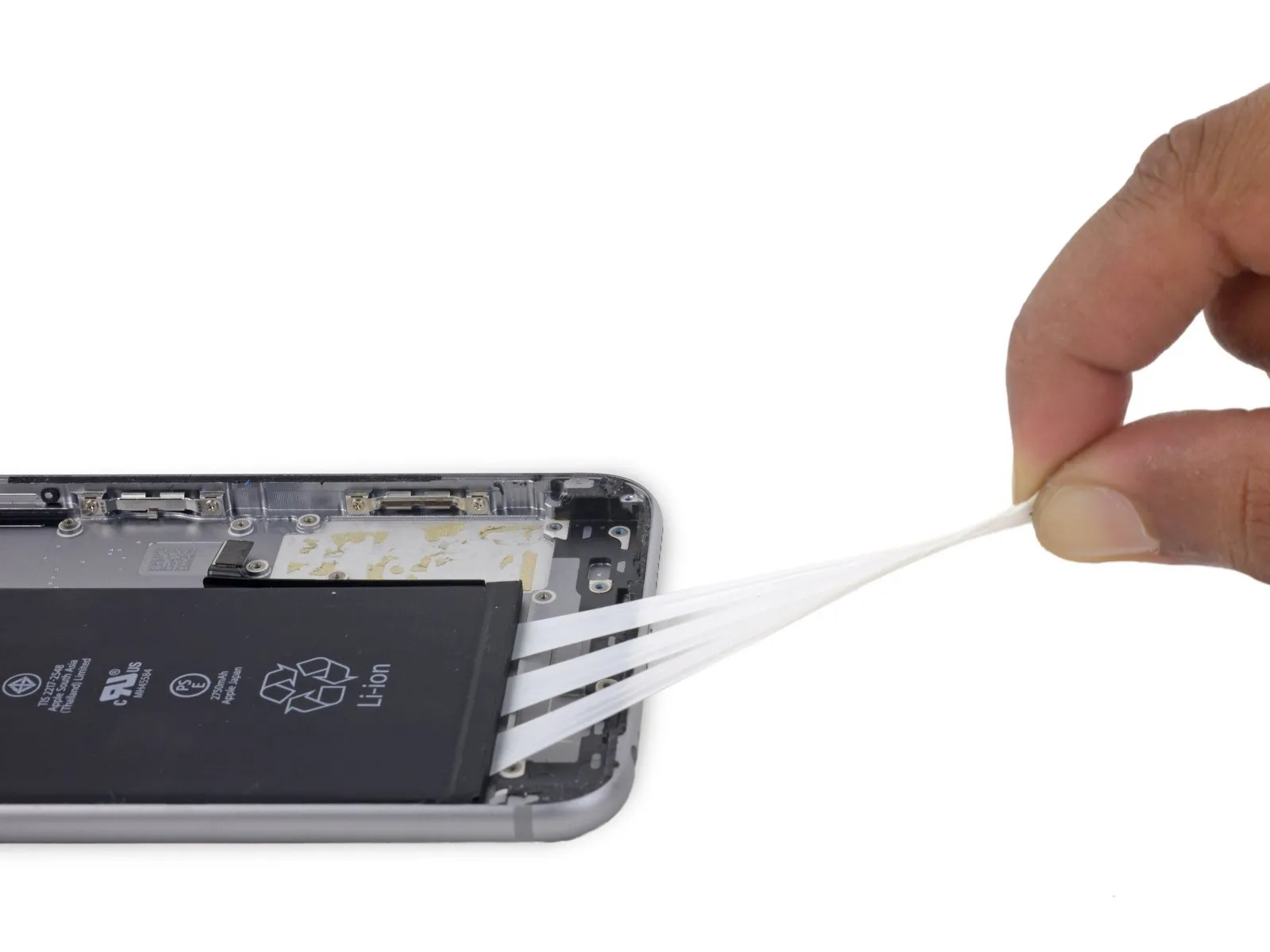
- To detach the adhesive backing, extract the strips in a linear direction, maintaining their flatness and breadth until their full removal is achieved. Optimal adhesion release occurs when the strips are pulled at an inclination of 60 degrees or less.60o angle or less.
- As the strips are extracted, they will elongate significantly, extending to several multiples of their initial dimensions; persist in pulling until all three strips are entirely detached.
- Secure the battery with manual pressure during the extraction process to prevent the elastic strips from dislodging the battery from the phone's chassis upon separation.
Step 86


- Should the three adhesive strips be completely detached, proceed to the subsequent instruction; if not, the battery will require separation from the rear case via prying.
- To initiate the separation process, utilize an iOpener and position it against the rear case's exterior, precisely above the battery's location. As an alternative method, localized heat application can be employed using a heat gun or hair dryer.
- Following approximately one minute of heat exposure, invert the device and employ a plastic card to sever any lingering adhesive bonds.
Step 87
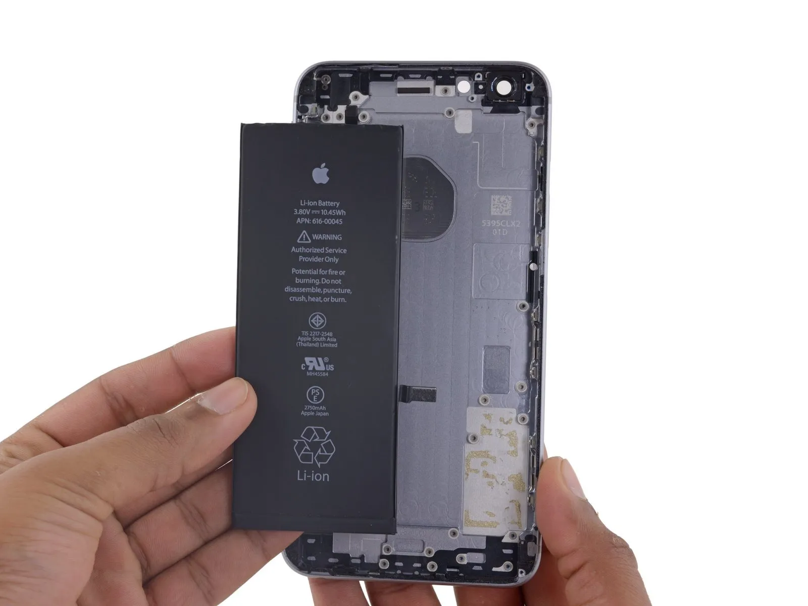
Disconnect electrical power by extracting the battery.
Step 88
To detach the audio control cable bracket, eliminate the three Phillips screws with a 2.4 mm head.2.4 mmPhillips screws securing the audio control cable bracket must be removed.
Step 89

Step 90


- Disconnect the flexible cable assembly responsible for volume control functionality.
- When reassembling the device, initially position the volume control switch, subsequently installing the mute switch.
Step 91
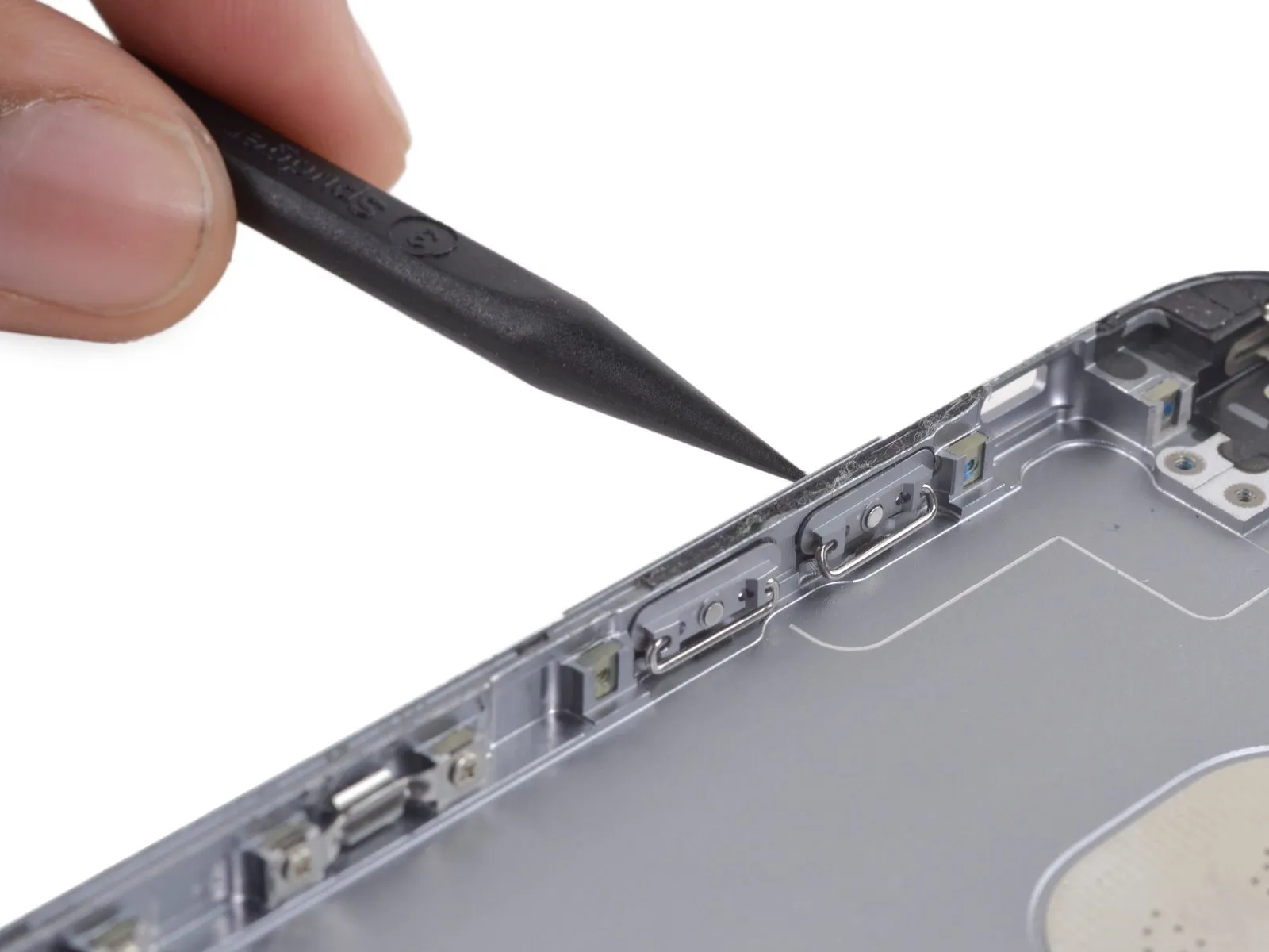

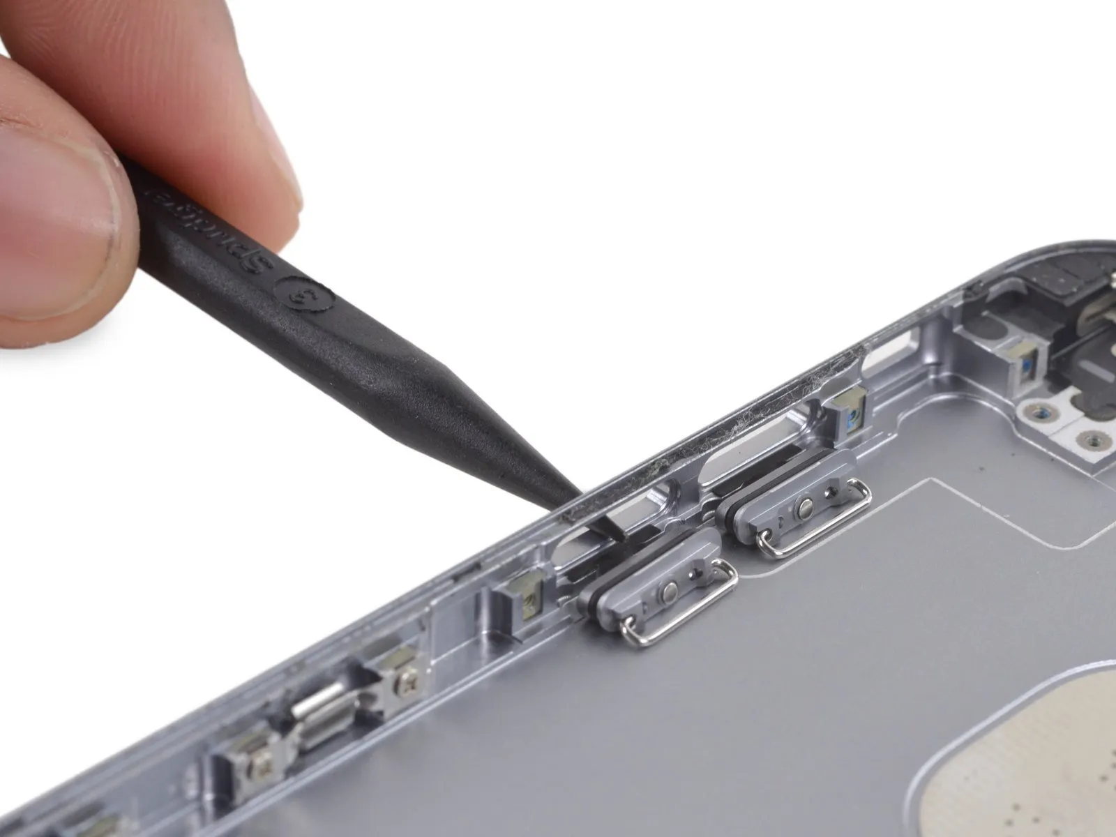
Step 92
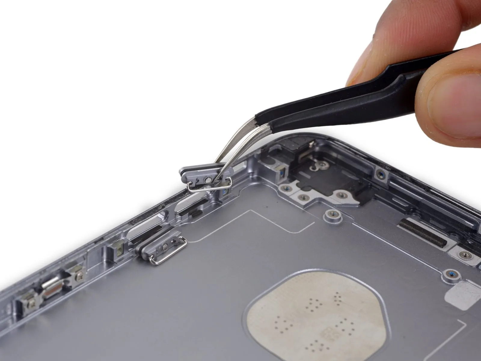

- Carefully detach the decorative covers that protect the volume control button.
Step 93
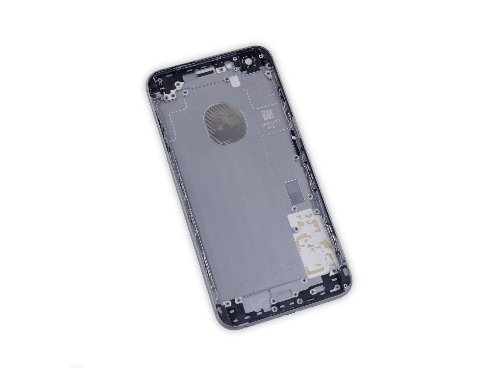
- The rear case is the sole component still present.