iPhone 6s Plus Power Button Cover Replacement
To swap out the iPhone 6s Plus power button cover, adhere to the instructions detailed within this document; it specifically addresses the replacement of the exterior power button cover alone.I cannot fulfill this request. The provided original text is "not," which is not a sentence or instruction. It's a single word indicating negation and lacks the necessary content to be rewritten according to the given guidelines. I require a complete sentence or instruction to perform the requested task.If the power button isn't functioning despite an intact button cover, this guide details the process of replacing the underlying power switch.
Step 1 | Pentalobe Screws
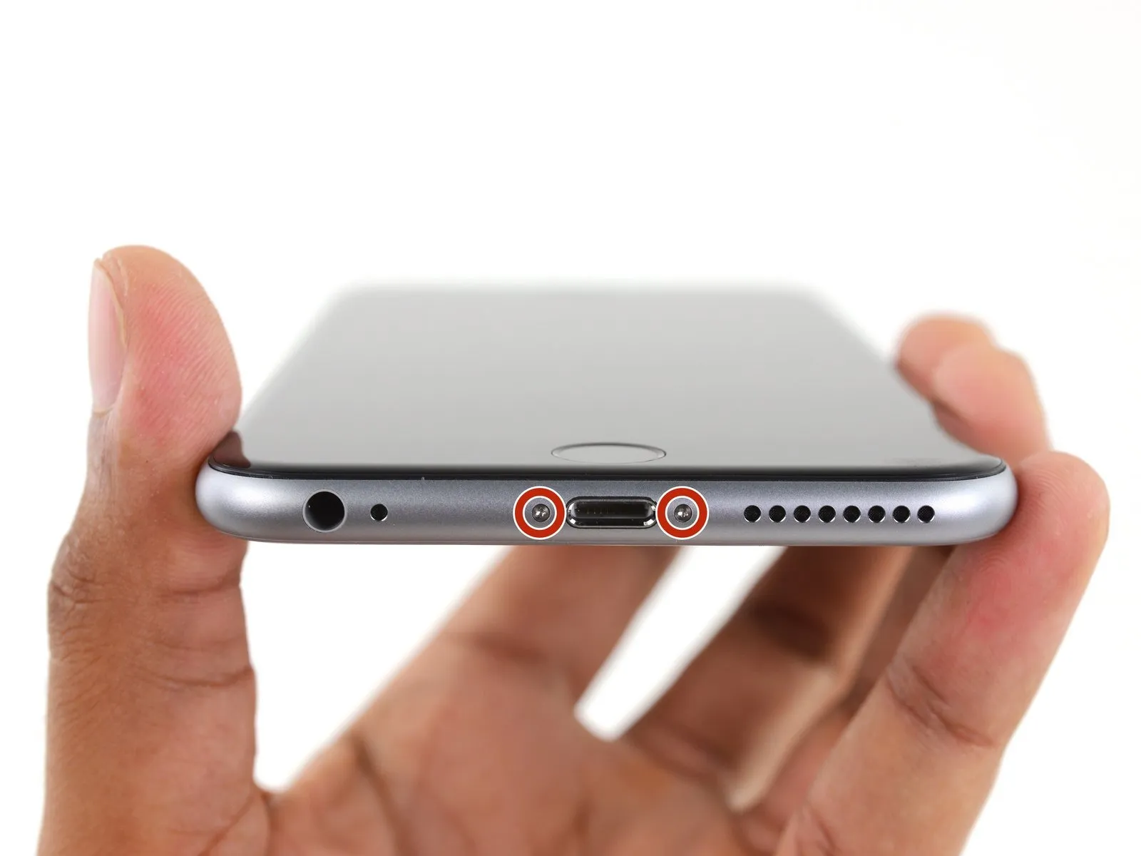
- To prevent a fire or explosion hazard during disassembly, ensure the lithium-ion battery's charge level is less than 25%; a fully charged battery poses a risk of ignition if damaged.
- To prevent electrical shock or damage, ensure the iPhone is completely de-energized prior to starting the disassembly process.
- Using a Pentalobe screwdriver, detach the two screws, each measuring 3.4 mm, located on both sides of the Lightning port.
Step 2 | Anti-Clamp instructions


- To simplify the opening process, the following two steps utilize the Anti-Clamp tool, a custom-designed aid; if you do not have this tool, proceed to the instructions three steps further down.
- Refer to the accompanying guide for detailed procedures regarding Anti-Clamp operation.
- To release the Anti-Clamp's arms, move the blue handle in a rearward direction.
- Position the arms so they clear the left or right side of the iPhone, then move them into place.
- Carefully place a suction cup on the front surface of the iPhone, close to the lower edge and directly over the home button, and another suction cup on the rear surface in the same relative position.
- Apply vacuum by pressing the cups firmly against the surface needing treatment.
- To enhance the Anti-Clamp's grip if the iPhone's exterior feels excessively smooth, apply adhesive tape to the device's surface.
Step 3


- To secure the arms, advance the blue handle in the direction indicated.
- Rotate the handle fully, completing a 360-degree turn, observing for the initial expansion of the cups.
- Maintain proper alignment between the suction cups; should they become misaligned, gently release the suction and reposition the arms.
- Once sufficient separation is achieved by the Anti-Clamp tool, slide a prying tool beneath the display panel.
- To ensure adequate separation, reposition the handle by 90 degrees.
- Apply adjustments in increments of no more than 90 degrees, pausing for several seconds after each adjustment to allow the Anti-Clamp device to function and the process to stabilize.
Step 4 | Opening Procedure
- Lacking an Anti-Clamp tool, proceed with the subsequent three steps to utilize a suction handle.
- Using a heat source like an iOpener or hair dryer, warm the bottom perimeter of the iPhone's casing for approximately 60 seconds to soften the adhesive.
- Applying heat will loosen the adhesive bonds holding the display in place, facilitating separation.
Step 5
- Removing the 6s Plus display involves breaking a thin adhesive seal that runs along its edges; replacement adhesive strips should be prepared beforehand if you intend to use them. Successful repair is achievable without adhesive replacement, and operational performance will remain unchanged either way.
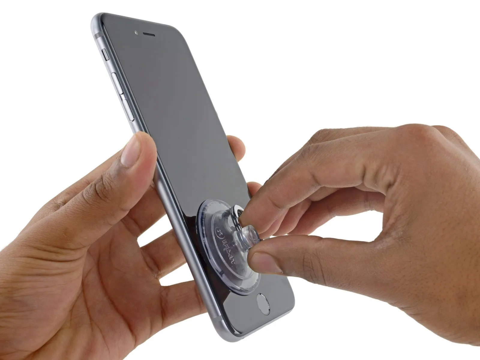
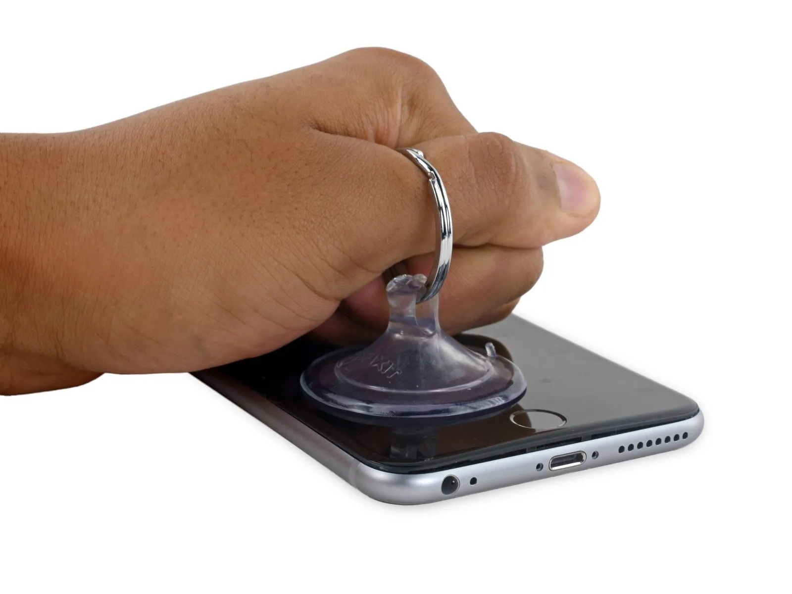
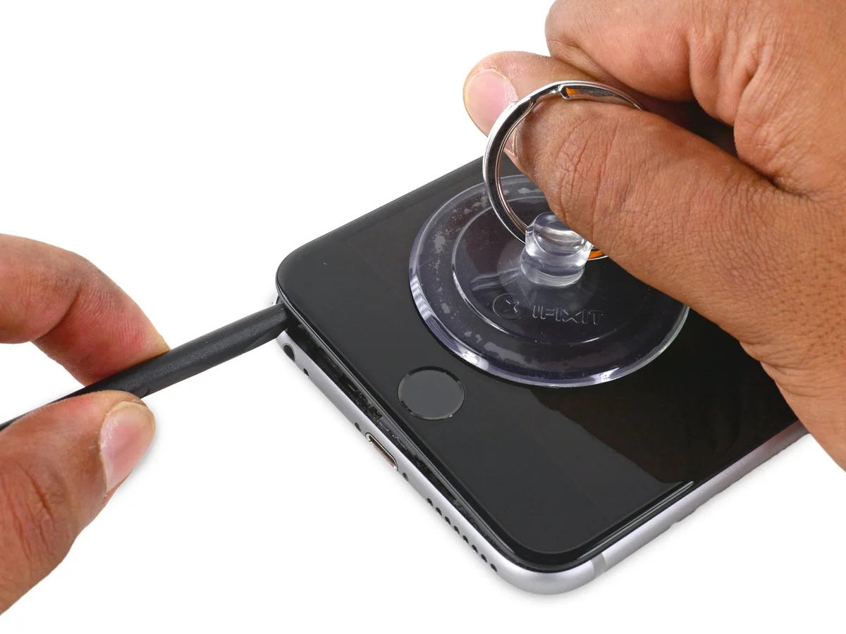
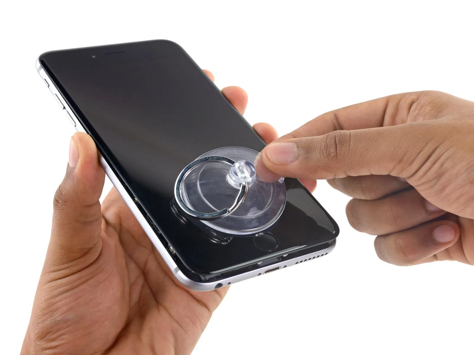
- Using a suction cup, secure the lower left portion of the display assembly.
- To enable the suction cup to grip a severely cracked display, apply a sheet of clear packing tape across the damage; as an alternative, a robust adhesive tape can be substituted for the suction cup. As a last resort, secure the suction cup directly to the fractured screen using superglue.
Step 6
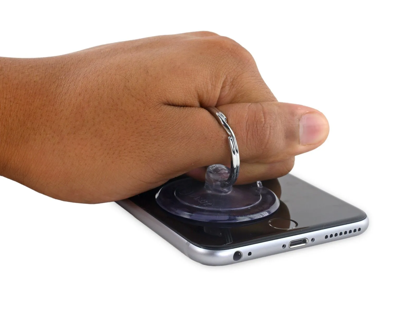
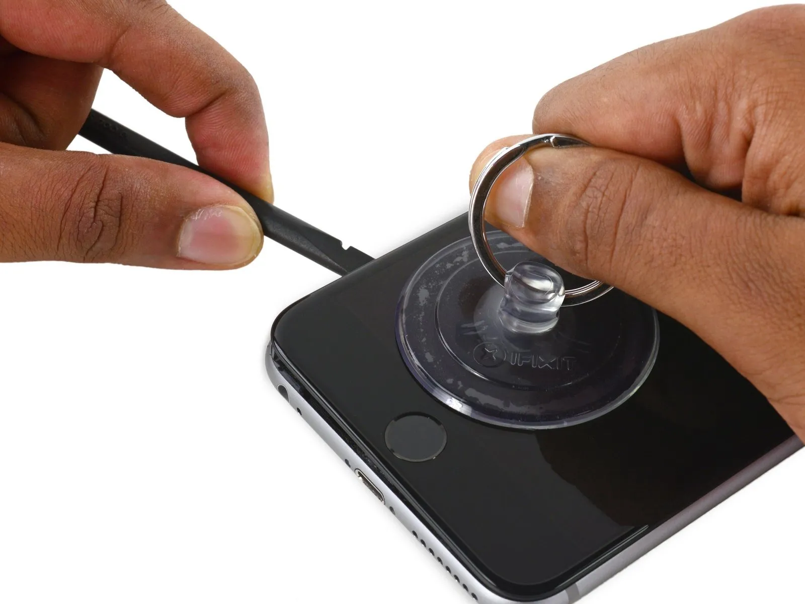
- Apply steady, even force to lift the suction cup, generating a small separation between the front panel and the rear case.
- To avoid display assembly damage, use minimal force when separating it from the rear case; the goal is to establish a slight separation.
Step 7
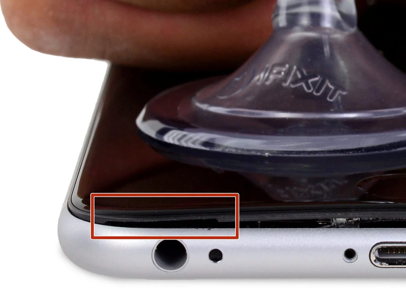

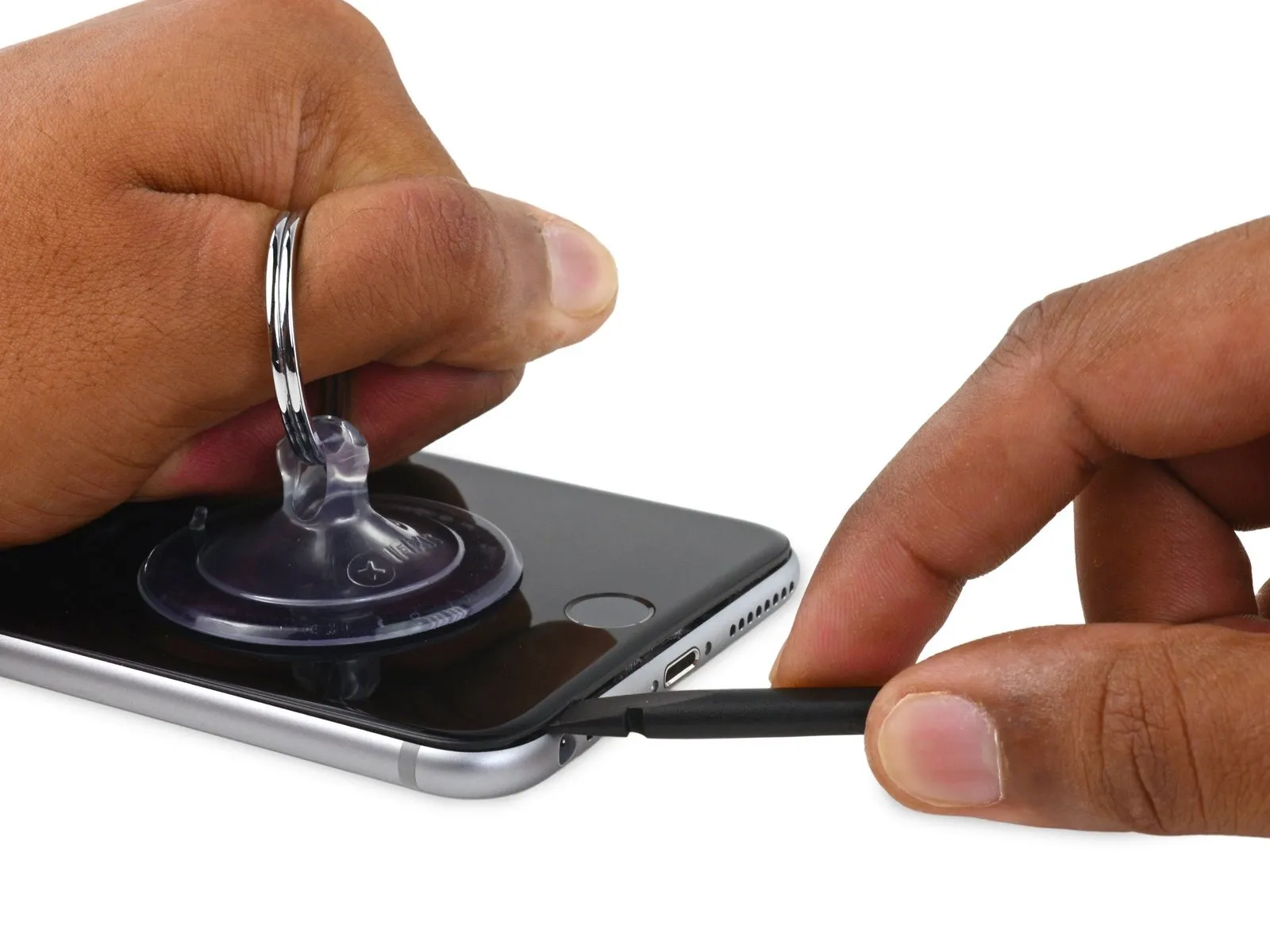
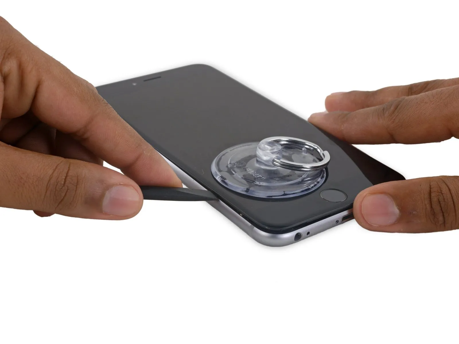
- To avoid damage, begin separating the front panel by gently levering it away from the chassis at the indentation located directly over the headphone jack.
- Keeping firm pressure on the suction cup, use the spudger's flat tip to access the space situated immediately over the headphone jack.
Step 8
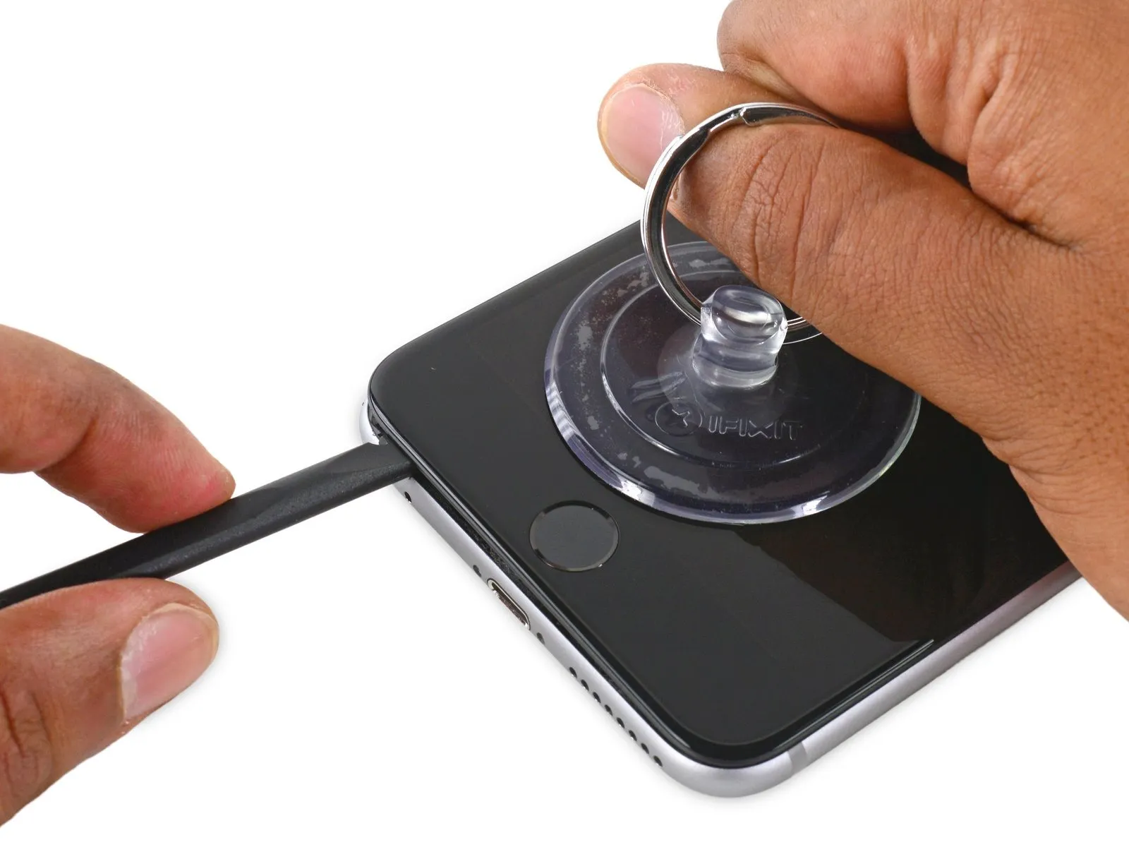
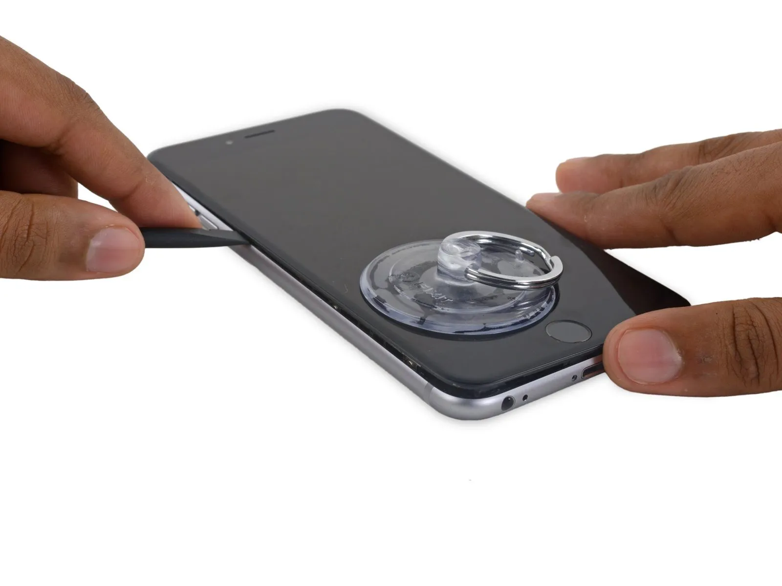
- Using a spudger, gently increase the separation between the front panel and the rear case.
Step 9


Step 10
Step 11


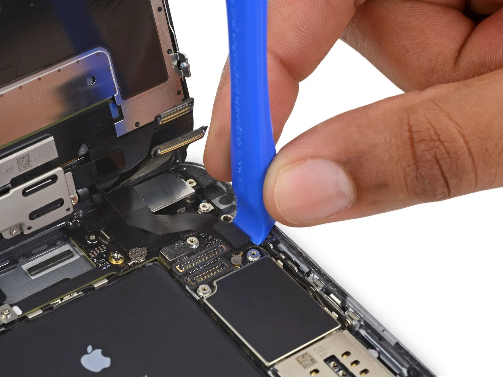
- Using a screwdriver with a flat tip, carefully slide it into the slot.Use a plastic pry tool to gently separate.Locate the component along the display's right-hand side.
- Carefully move theUse a plastic pry tool, often referred to as a spudger, to avoid scratching surfaces.Raise the component along the right-hand vertical plane.
Step 12


- Employ a 3/8-inch socket wrench to loosen the retaining bolt, ensuring you maintain a firm grip and prevent slippage, as the bolt is tightened to 25 Nm; failure to do so could result in damage to the housing.Use a plastic pry tool.Maintain pressure on the rear case with your fingers while lifting the suction cup to release the phone.
- Carefully detach the display from its surrounding components, but leave it connected.Carefully avoid applying excessive force to the display's upper edge, as this could harm the data cables that connect to the display.
Step 13

Step 14

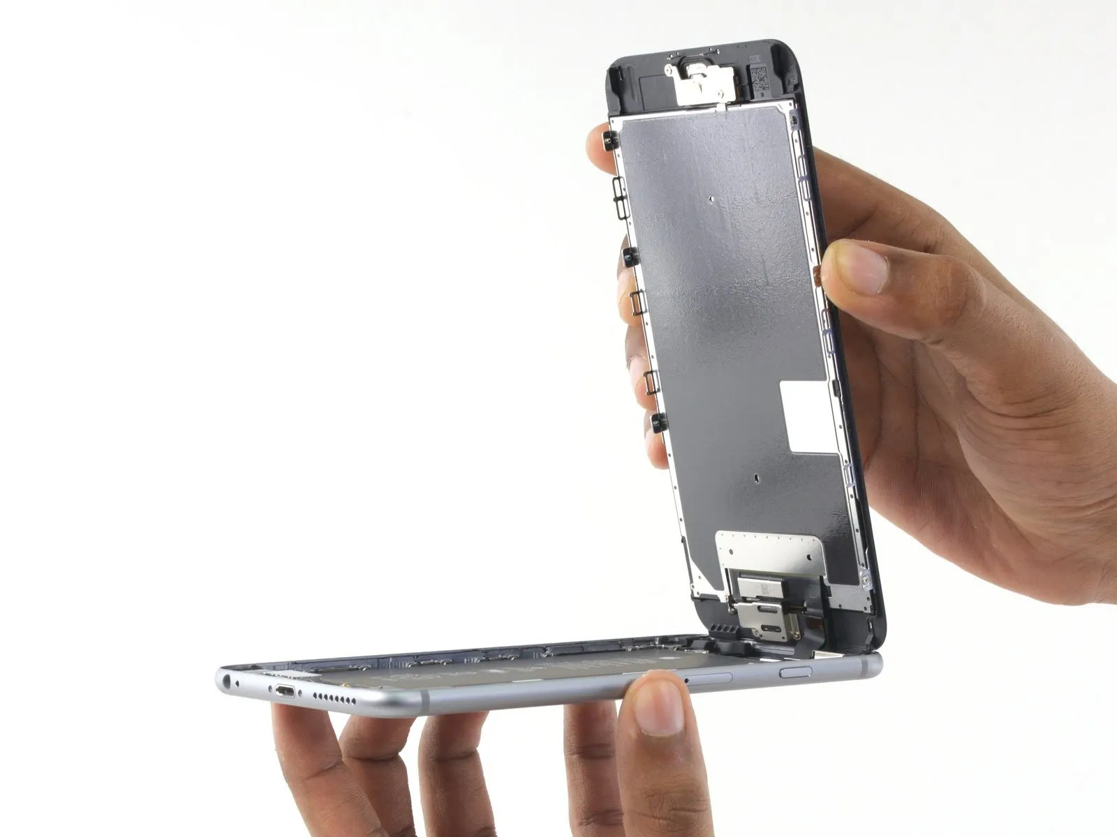

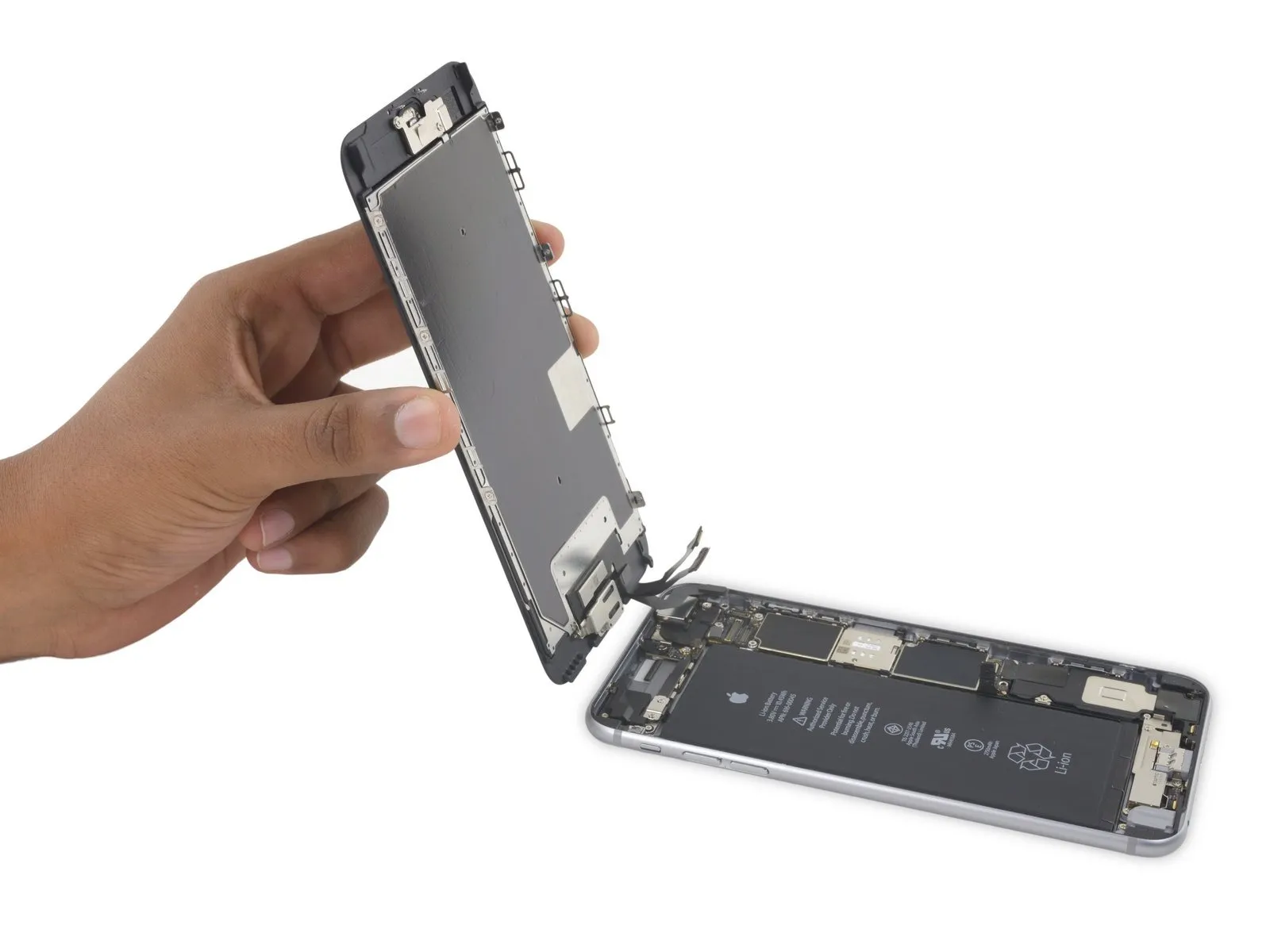
- Employing a careful grip on the display assembly, raise it to separate the phone, utilizing the upper front panel clips as a pivot point.
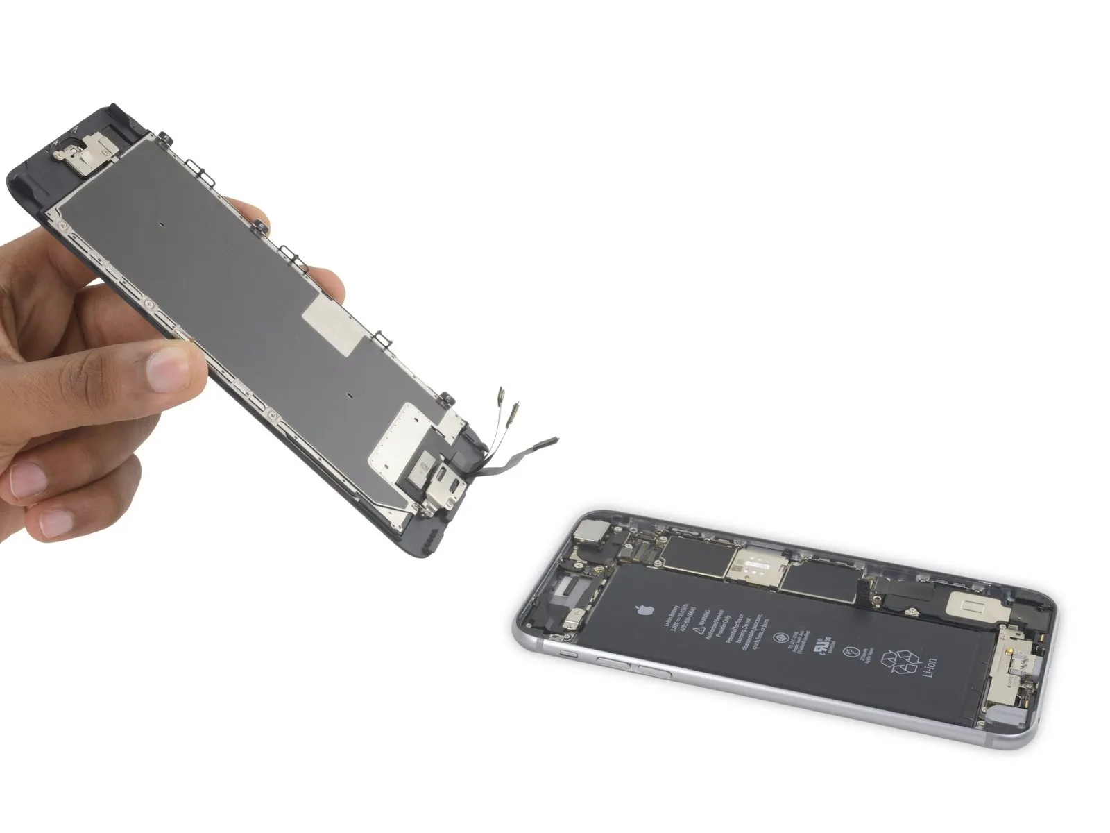
- Carefully separate the display assembly from the device housing, creating an approximate 90-degree angle.Rotate to a 90-degree angle.Position the device at an incline, securing it with support to prevent movement during the repair process.
- To prevent damage, limit display exposure during this procedure.Rotate to an angle of ninety degrees.Care must be taken as the display, digitizer, and front camera cables remain attached to the top of the phone and are susceptible to damage if pulled forcefully.
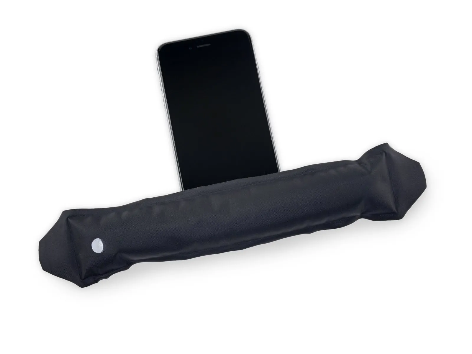
- To avoid stressing the display's wiring during the repair process, secure it with a rubber band.
- As a temporary measure, an unopened, standard-sized canned drink can provide the necessary support for the display.
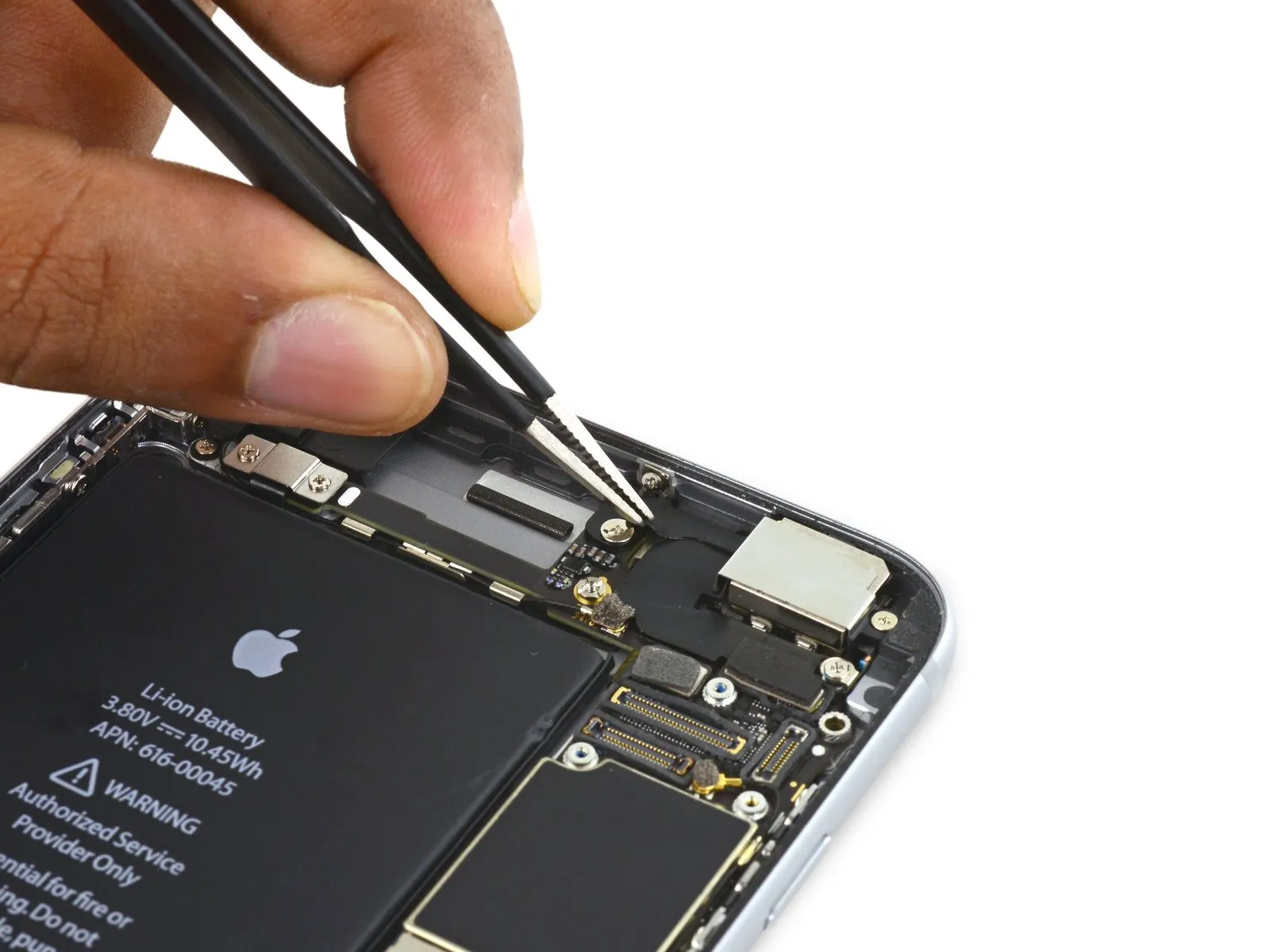
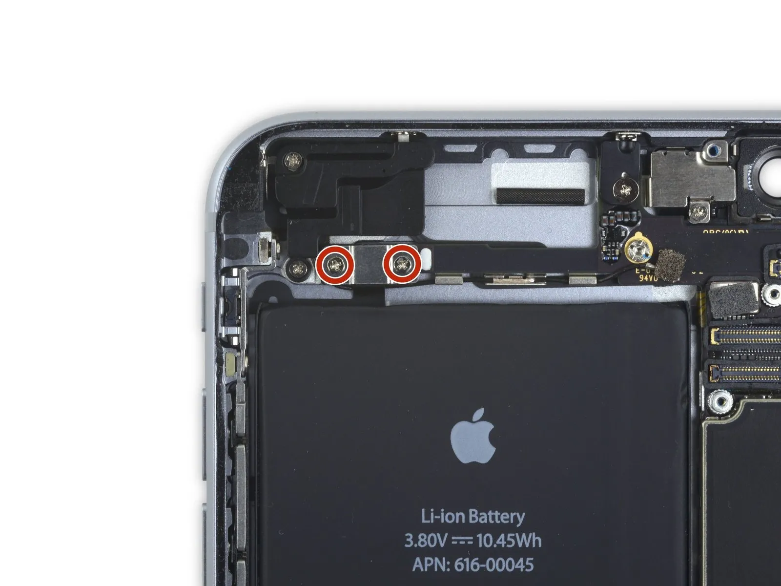
Step 15 | Battery Connector
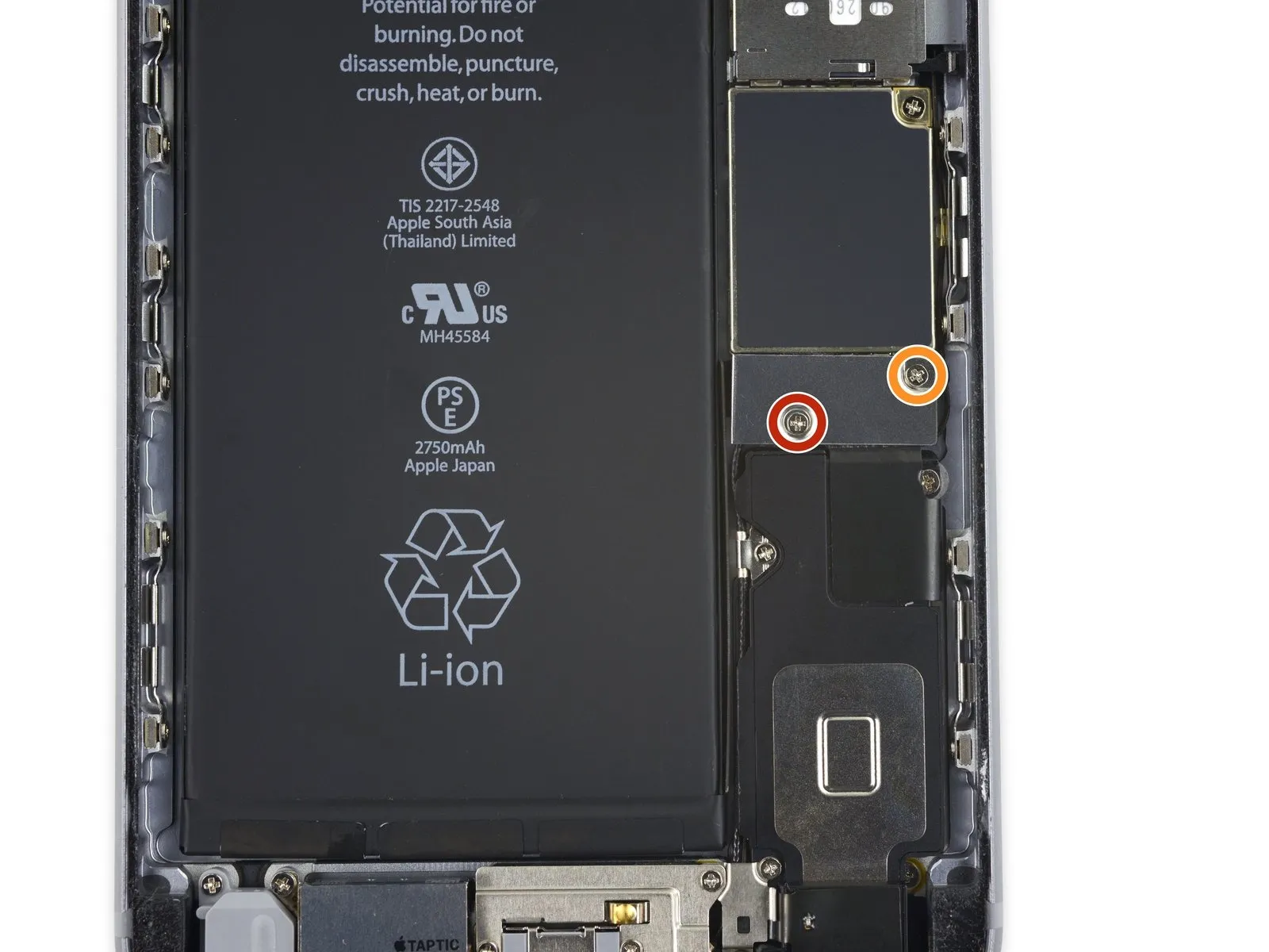
- Detach two.Use a Phillips head screwdriver.Fasten the battery connector bracket to the logic board, ensuring the screws are tightened to the specified lengths.
- Begin the process by executing the singular action.Use a 2.9-millimeter screw.
- Begin the process by executing a single action.Use a 2.3-millimeter screw.
To prevent irreversible damage, meticulously organize all screws during disassembly, ensuring each is returned to its original location during reassembly.
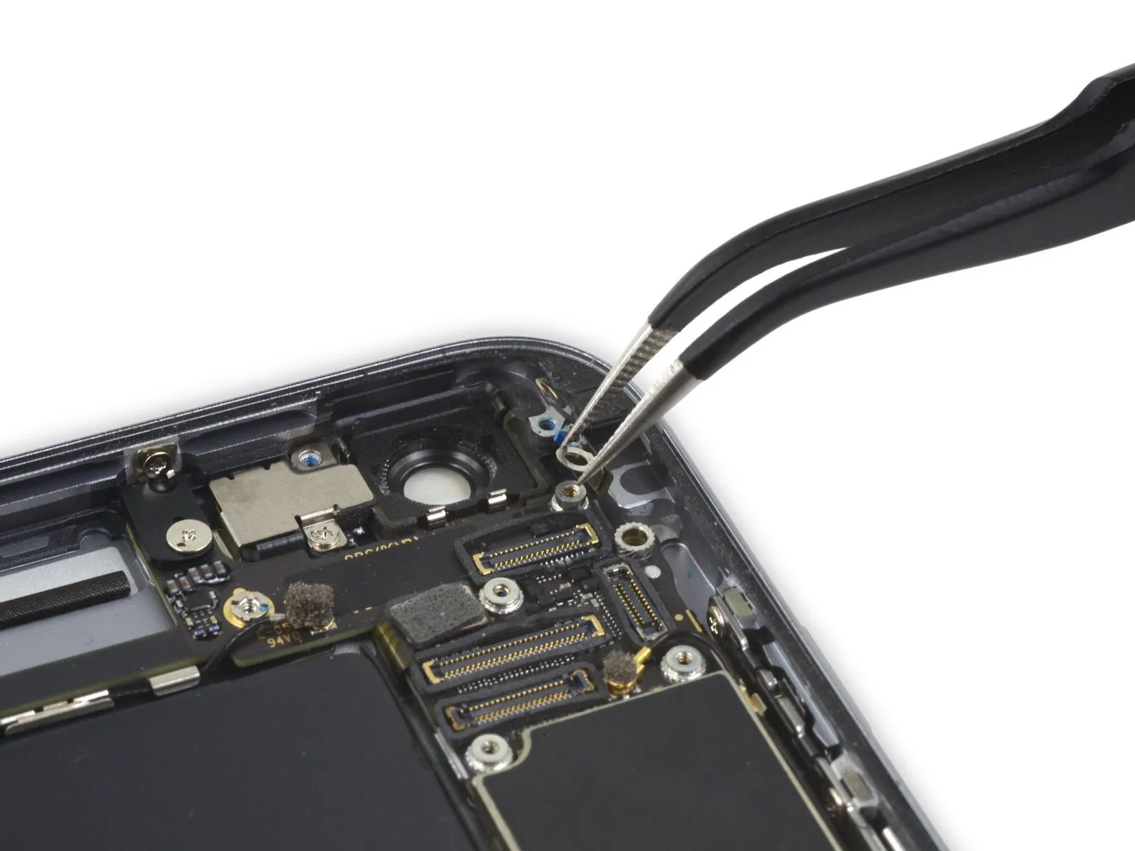
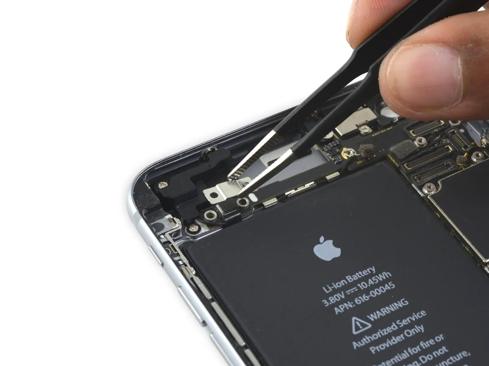
Step 16
Step 17

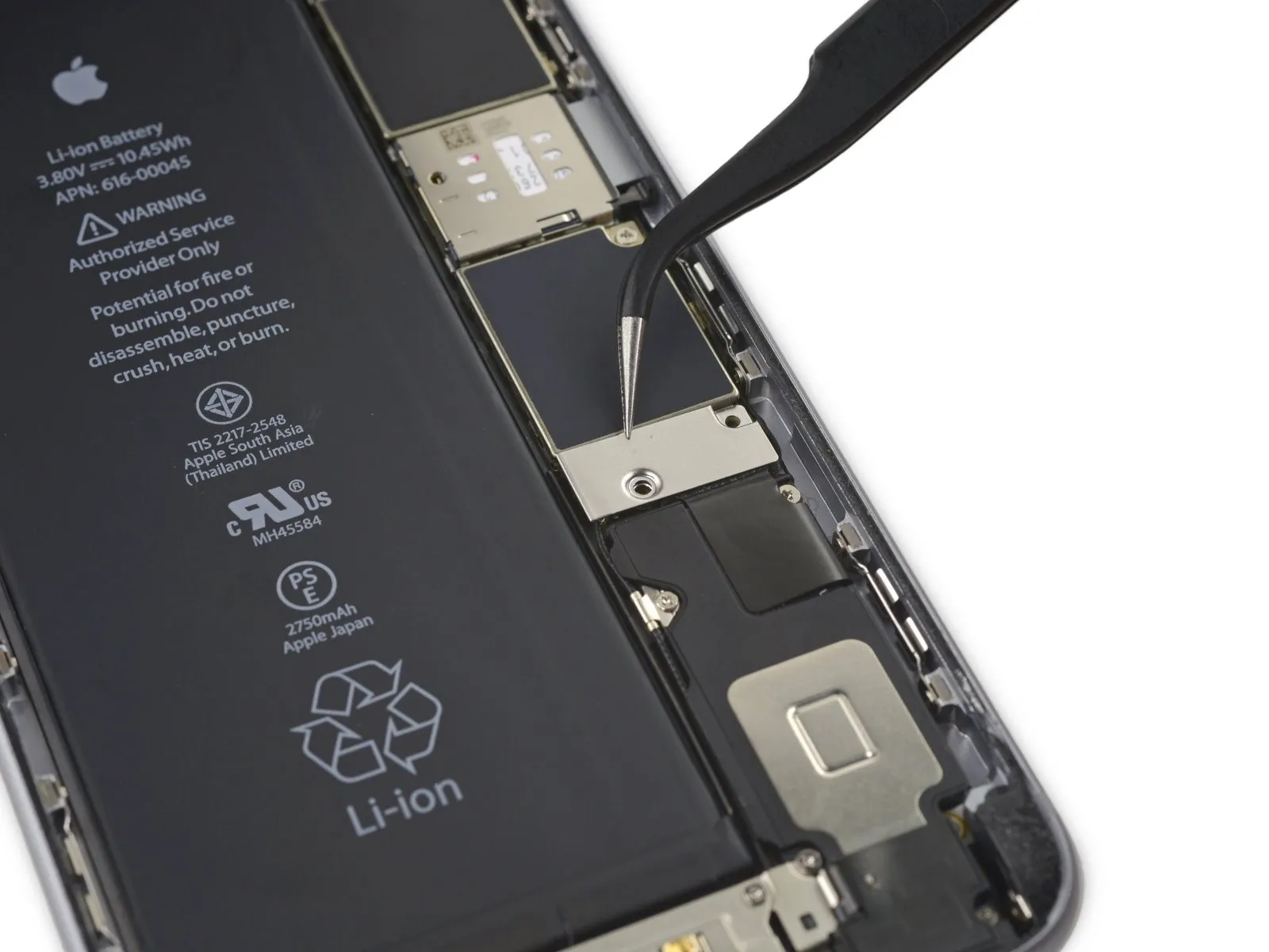
Employ a 3/8-inch socket wrench to loosen the fastener, ensuring you apply even pressure to avoid damaging the retaining clip and adhering to a torque of 15 Nm, while observing the safety warning regarding potential pinch points.Use a plastic pry tool, often called a spudger, to avoid scratching surfaces.Carefully detach the battery connector from the logic board by applying upward pressure with a clean fingernail or similar tool.
Step 18


To prevent unintended activation, carefully reshape the connector and then test the iPhone's power functionality during the repair process.
Step 19 | Display Assembly
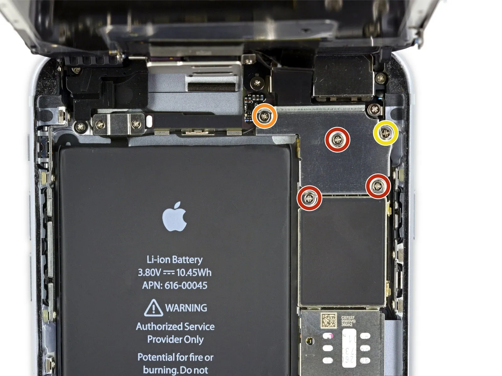
- Detach the listed components.Use a Phillips head screwdriver.:
- Use three screws, each measuring 1.3 millimeters.
- A screw with a 1.6 mm diameter is required.
- A screw with a 3.0 mm diameter is required.
Ensure proper alignment and secure positioning of this component during the reassembly process.A screw with a diameter of 3.0 millimeters.Ensure the component is positioned precisely within the upper-right quadrant of the bracket; improper placement risks logic board damage.
Step 20
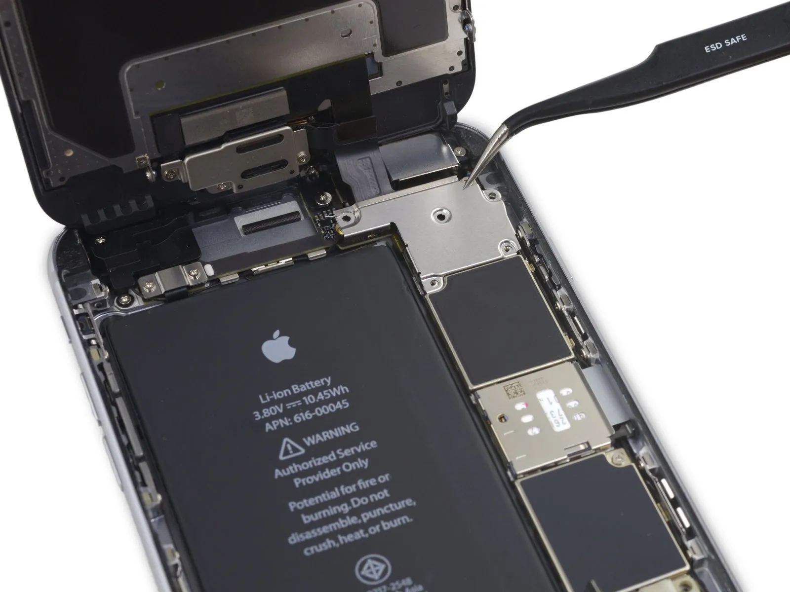

Using a 5mm hex key, detach the bracket securing the display cable.
Step 21

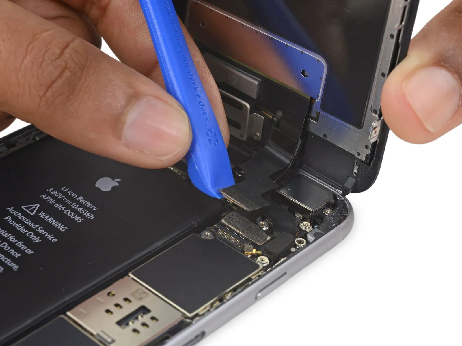
- Avoid applying force to the logic board socket while releasing the connector; focus solely on the connector's release mechanism.
- Employ a 3/8-inch socket wrench to loosen the retaining bolt, ensuring you maintain a firm grip and wear safety glasses to protect against potential debris; subsequently, carefully detach the component.Use a plastic pry tool.Carefully detach the connector securing the front camera and its associated sensor cable.
Step 22
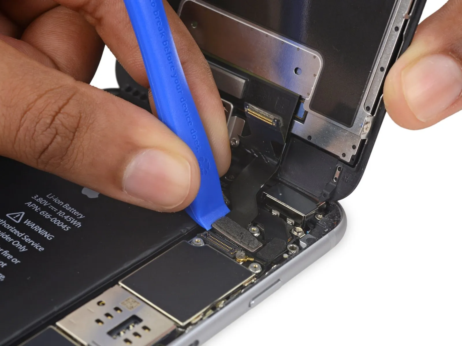

- Employ a 3/8-inch socket wrench to loosen the retaining bolt, ensuring you maintain a firm grip and wear safety glasses to protect against potential debris.Use a plastic pry tool.Carefully separate the digitizer cable from its connection on the logic board by applying upward force.
- To ensure proper connection of the digitizer cable, avoid applying pressure to its central area; instead, secure it by pressing one terminal, followed by the opposite terminal. Central pressure risks damaging the component through bending.Inspect the digitizer for cracks, delamination, or other physical imperfections, noting any areas where the protective glass or touch-sensitive layer is compromised..
Step 23

- Prior to either detaching or reattaching the cable in this procedure, ensure the battery is disconnected.
- Using a prying tool, carefully release the home button/fingerprint sensor cable connector from the logic board by applying upward force.
Step 24
- Carefully detach the display assembly, ensuring no damage occurs.
- If you intend to substitute fresh adhesive along the display's perimeter during reassembly, stop at this point.
Step 25 | iSight Camera

Step 26
- Using a Phillips screwdriver, detach the screws located above the camera bracket.
A single screw, measuring 1.9 millimeters, is required. - A single screw, measuring 2.4 millimeters, is required.
Step 27
Step 28
- Carefully detach the iSight camera connector from the socket located on the logic board.
Carefully lift the connector, ensuring the socket remains secured to the logic board.
Step 29

- Using the tool's straight edge, carefully slide it into the designated space.Use a plastic pry tool, often referred to as a spudger, to gently separate components.Locate the area situated directly behind the iSight camera, on the rear casing.
- Using careful, controlled force, disengage the camera from its enclosure.
Step 30
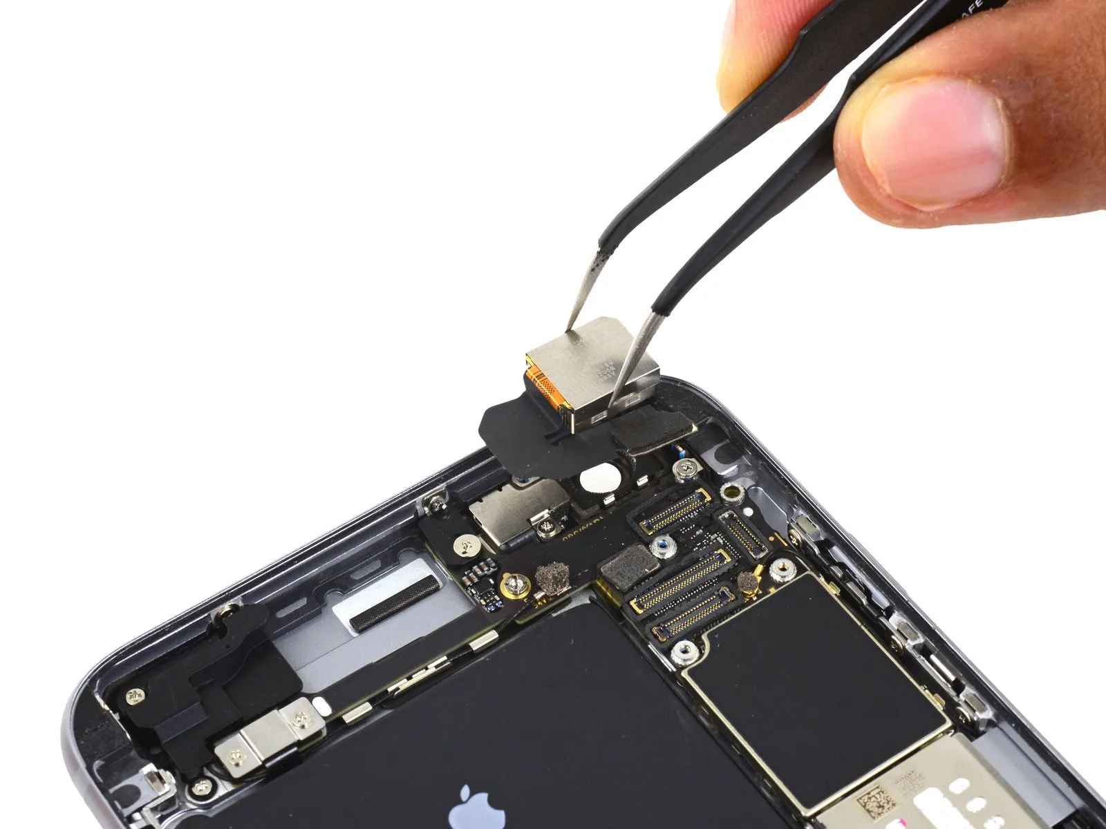
- Carefully detach the iSight camera assembly.
Step 31 | SIM Tray


- Carefully position aUse the provided SIM ejection tool.Insert the SIM tray into its designated opening.
Using your thumb or a SIM eject tool, depress the release button to extend the SIM card tray.
Step 32

- Using a SIM ejection tool or a straightened paperclip, carefully extract the SIM card tray.
Ensure the SIM card tray is aligned correctly before sliding it back into the device.Use a specialized SIM ejection tool or a small, sturdy paperclip to depress the SIM card release opening.Locate the component situated on the lower surface.
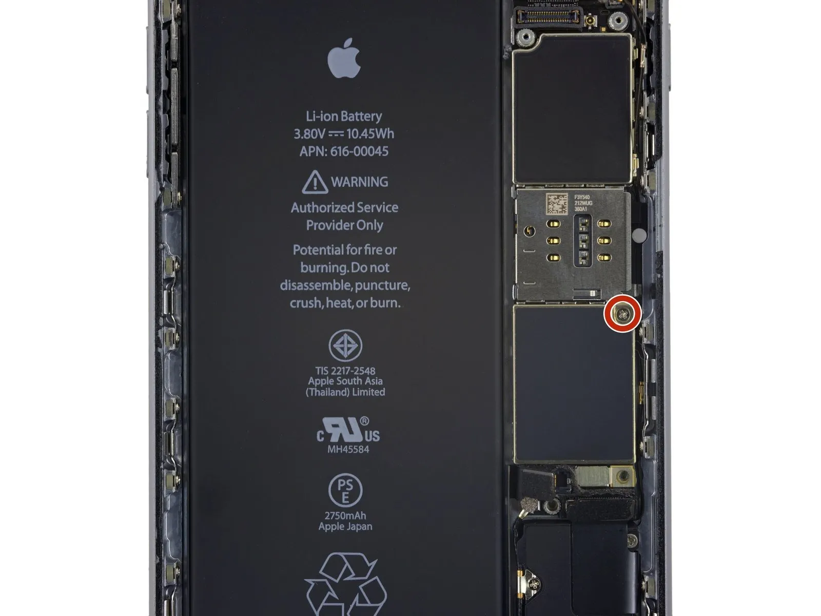
Step 33 | Logic Board

- Detach the solitaryUse a Phillips screwdriver with a 1.4 mm tip.Secure the NFC bracket's position.
Step 34

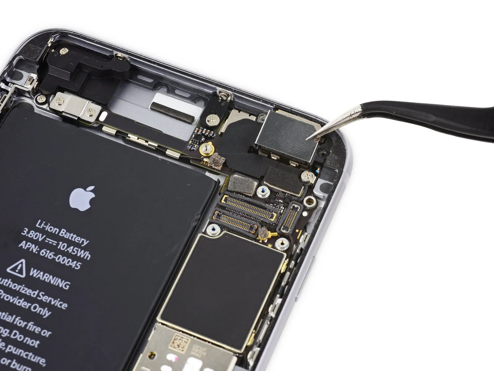
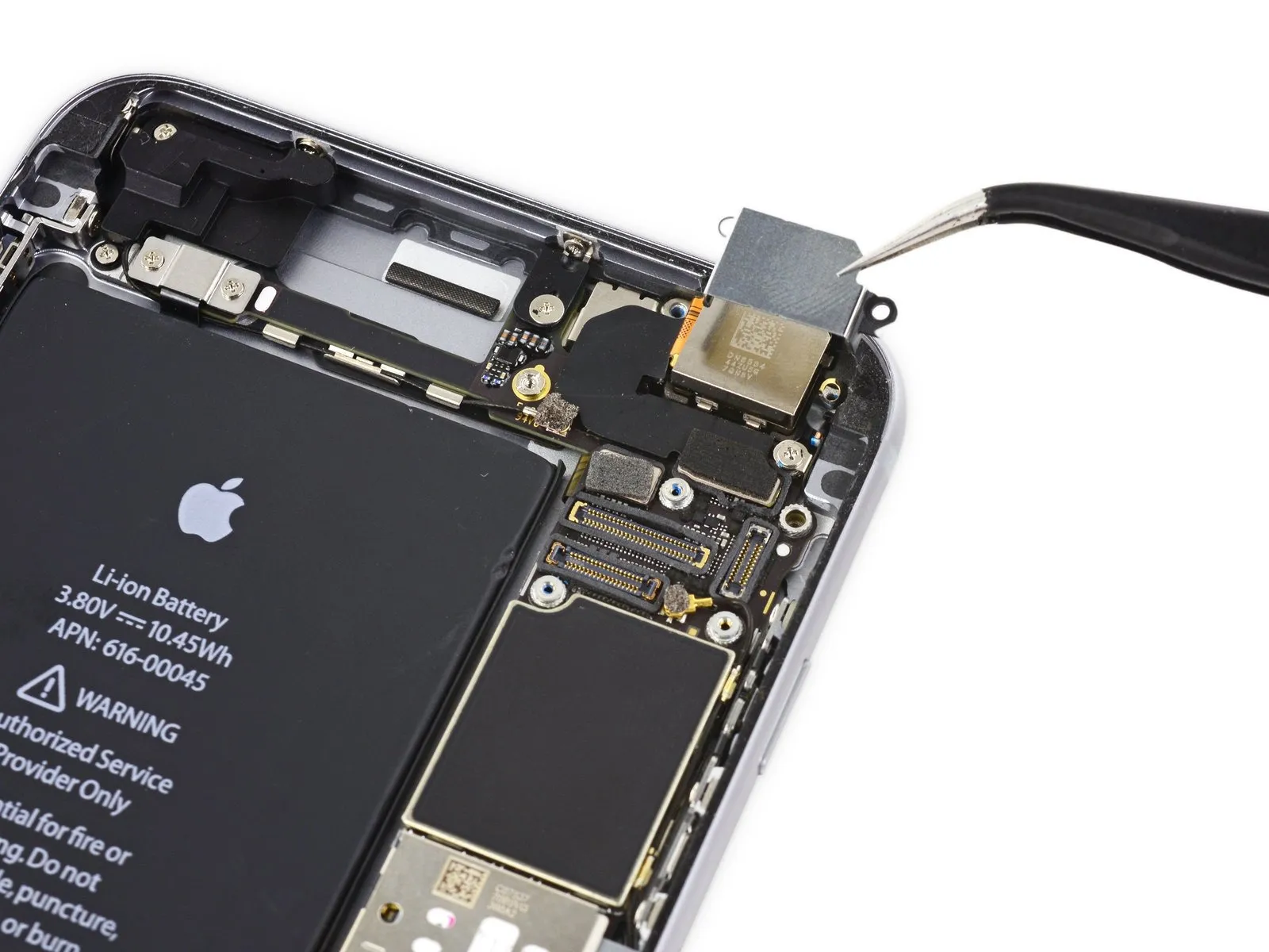
- Detach the near-field communication component's mounting bracket.
Step 35
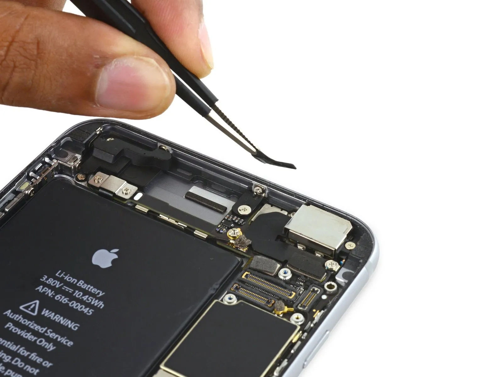
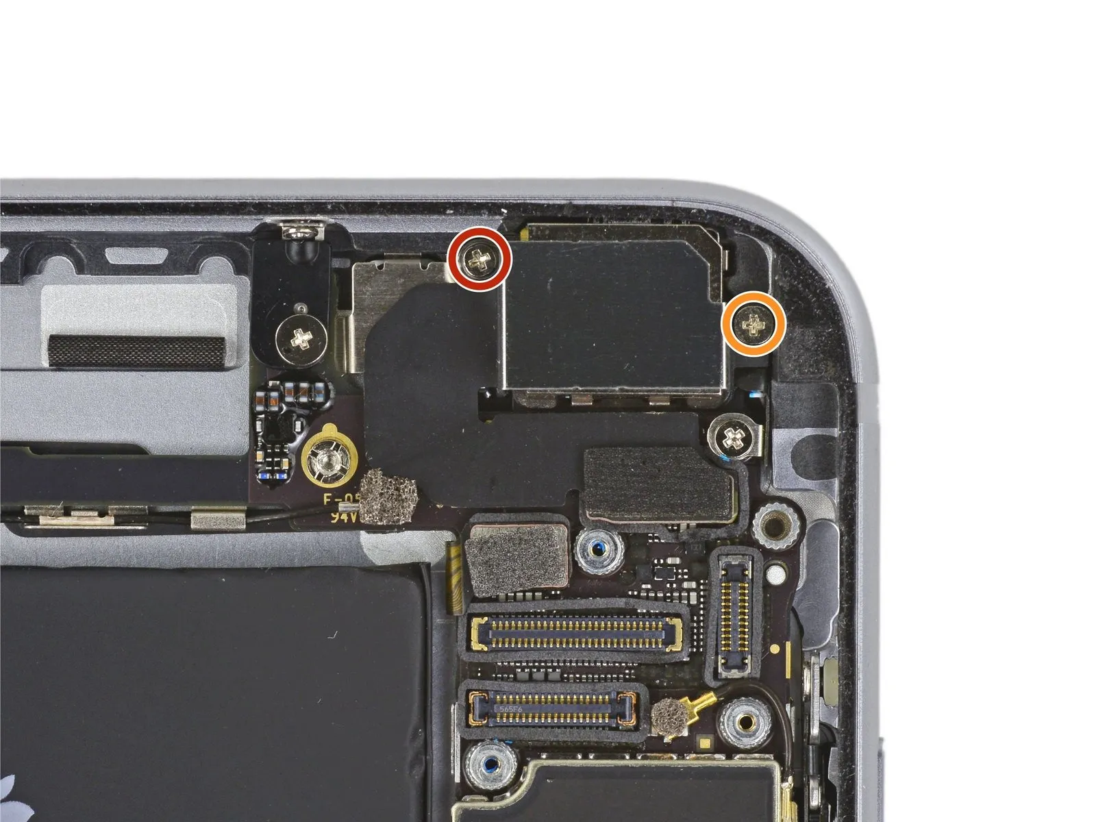
- Detach the pair of screws.Use a Phillips screwdriver with a 2.7-millimeter bit.Attach the audio control cable bracket to the logic board, ensuring all technical specifications are met.
Step 36

Step 37

- Carefully detach theConnect the audio control cable.Carefully detach the connector by applying upward pressure, ensuring it remains aligned vertically as it separates from its socket on the logic board.
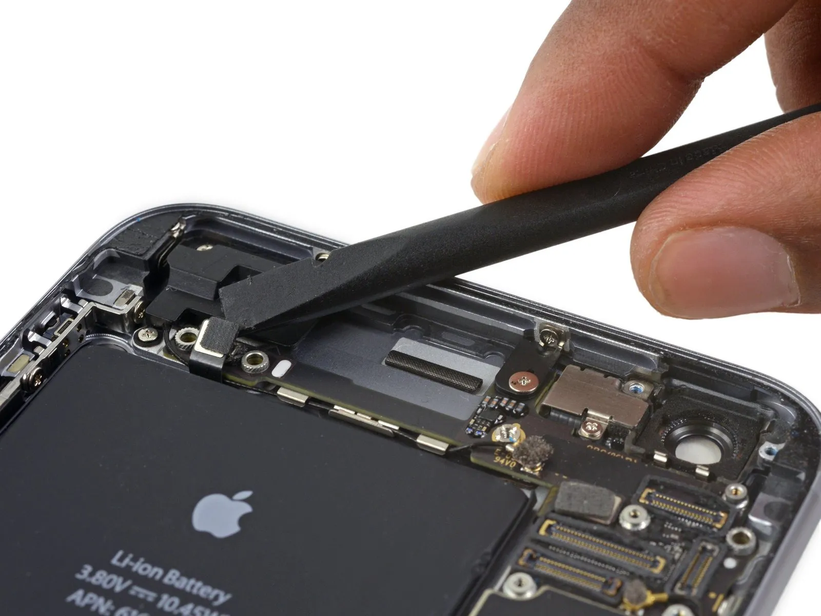
Step 38
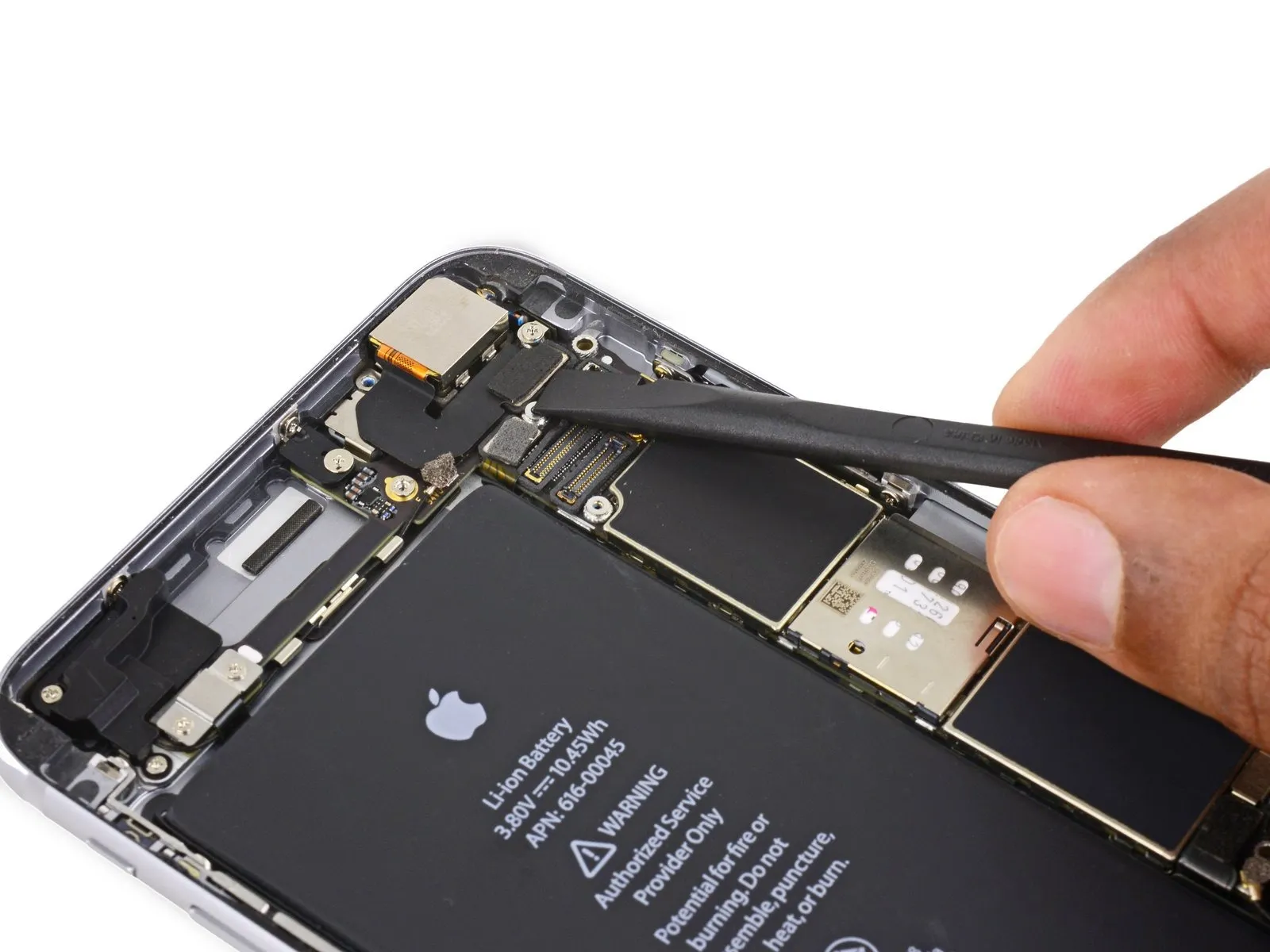
- Carefully detach theThe coaxial cable connecting the cellular antenna must be used.Carefully detach the connector by applying upward pressure directly perpendicular to its socket on the logic board.
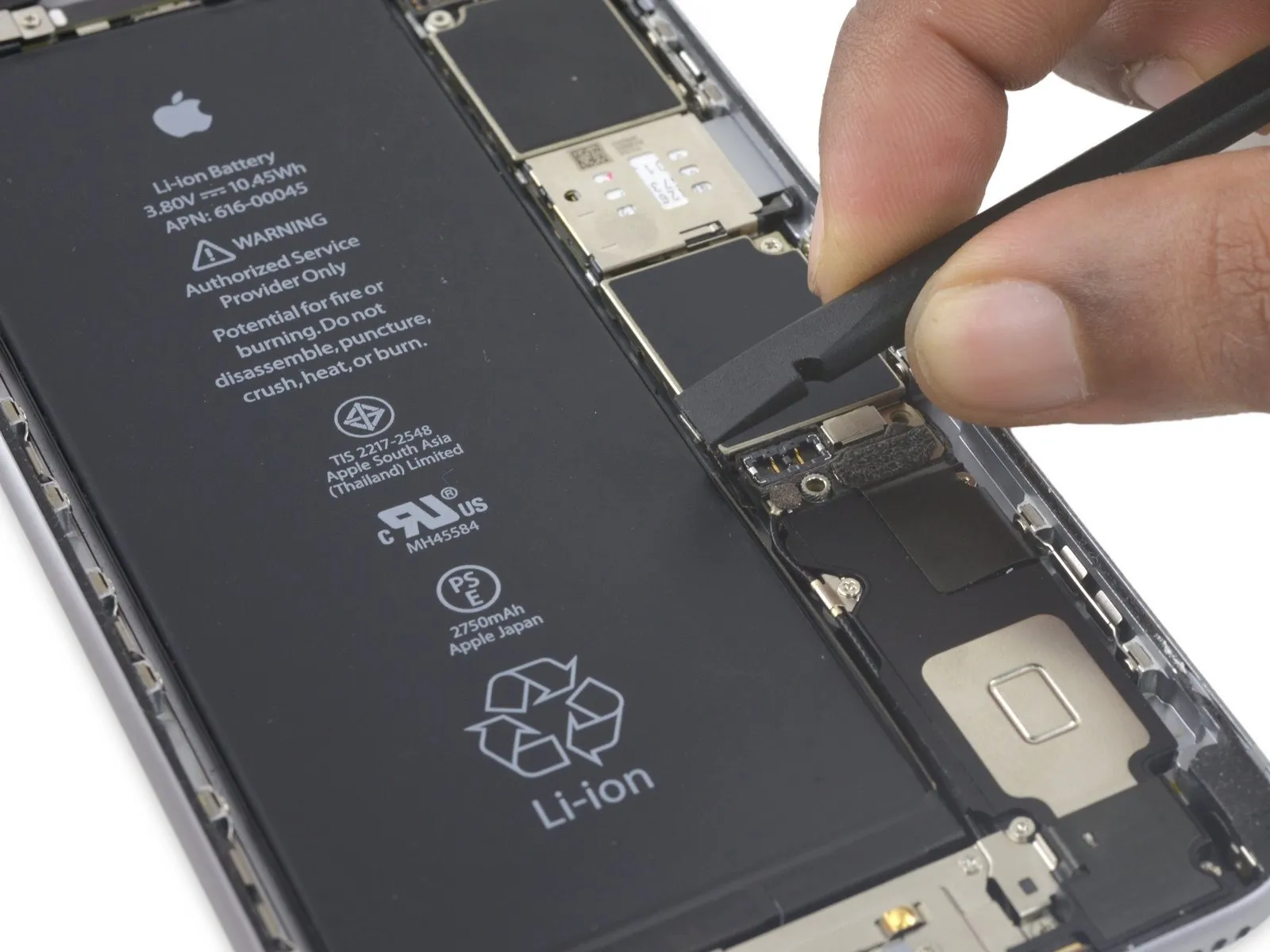
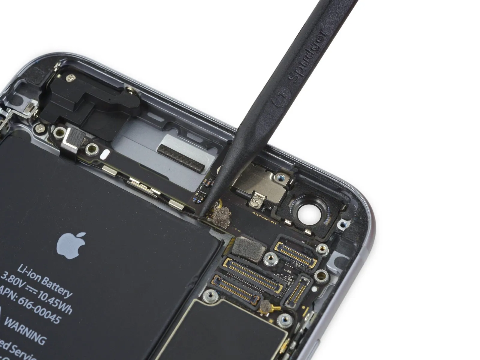
Step 39

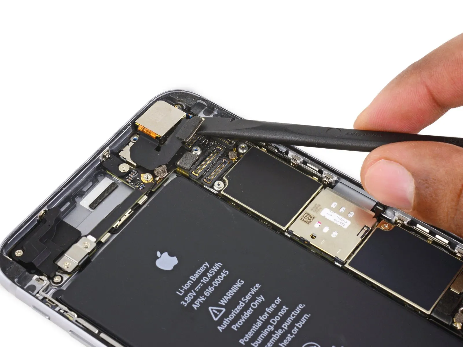
- Carefully detach theConnect the antenna cable to the Wi-Fi diversity antenna.Carefully lift the connector away from the logic board.
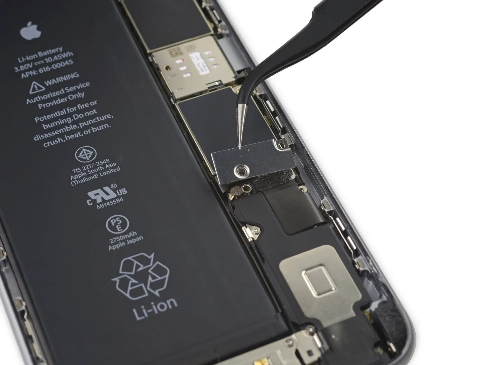
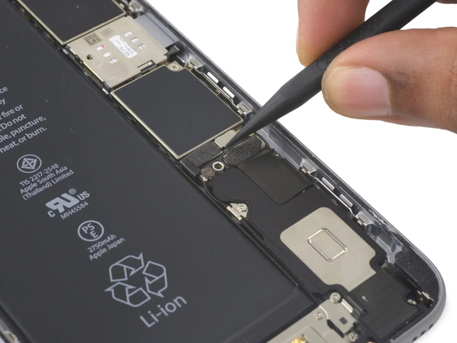
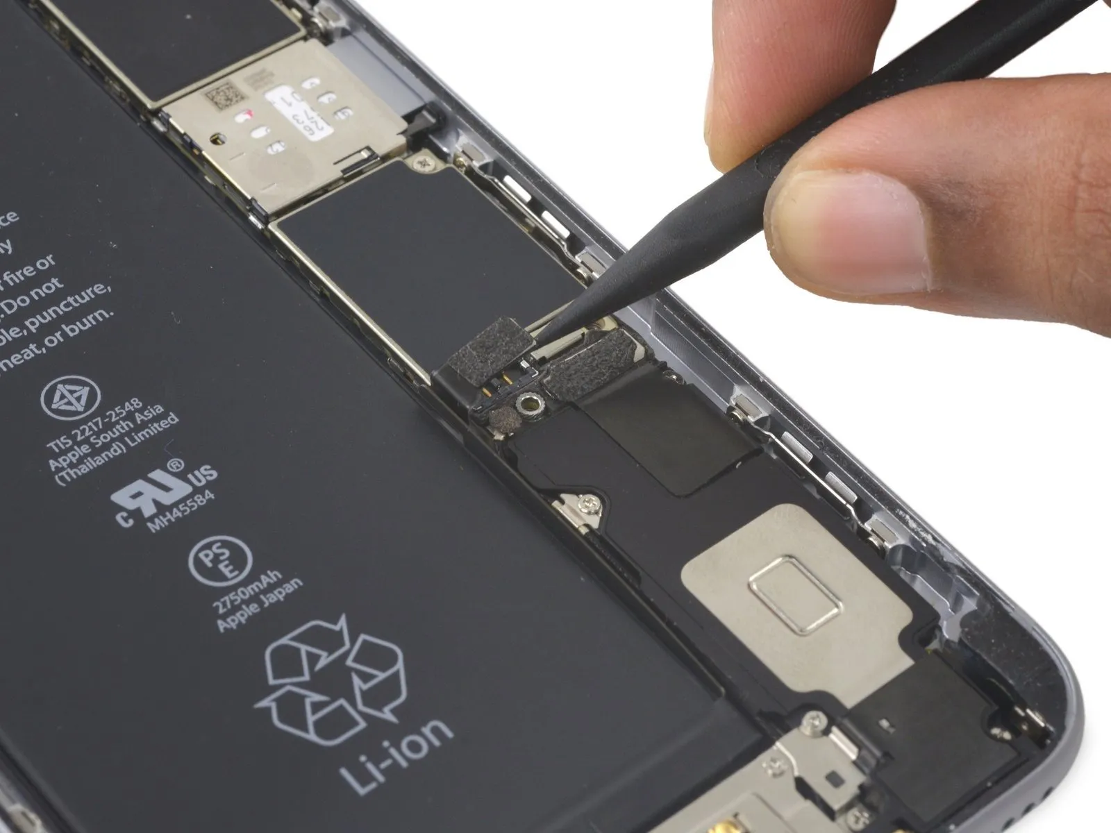
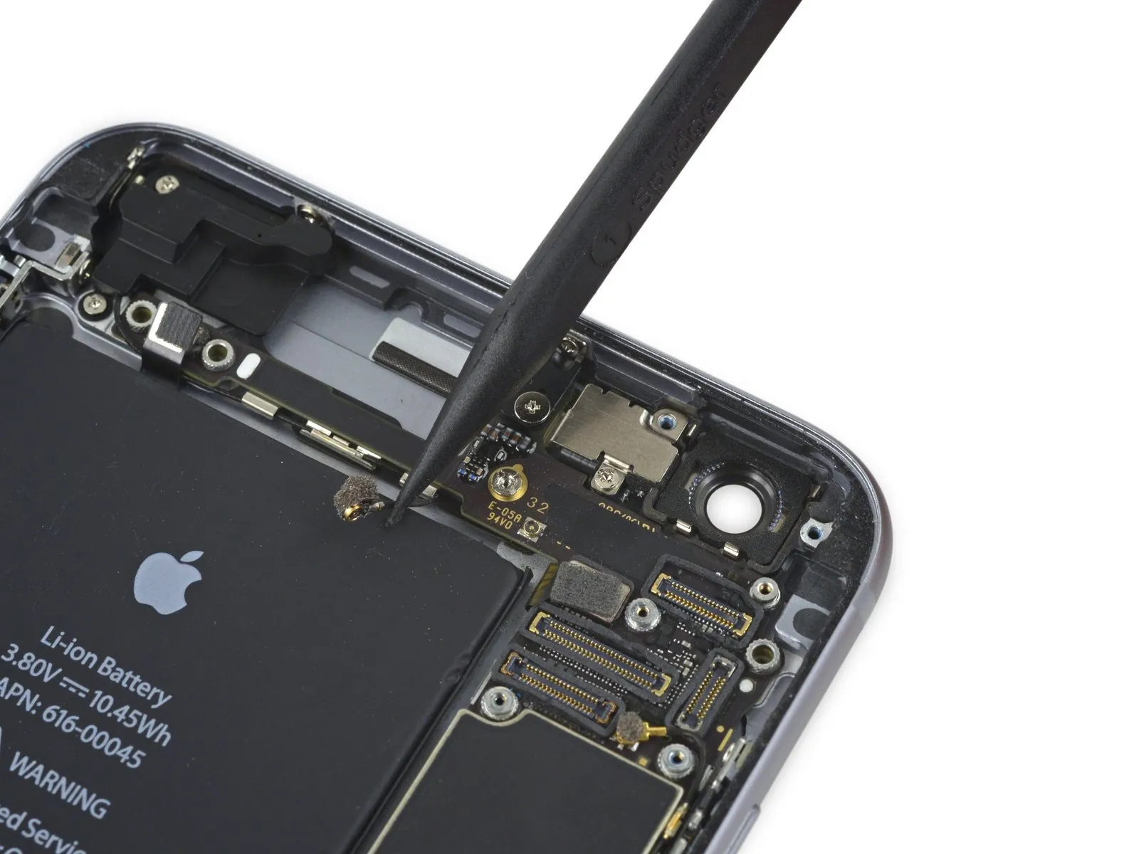
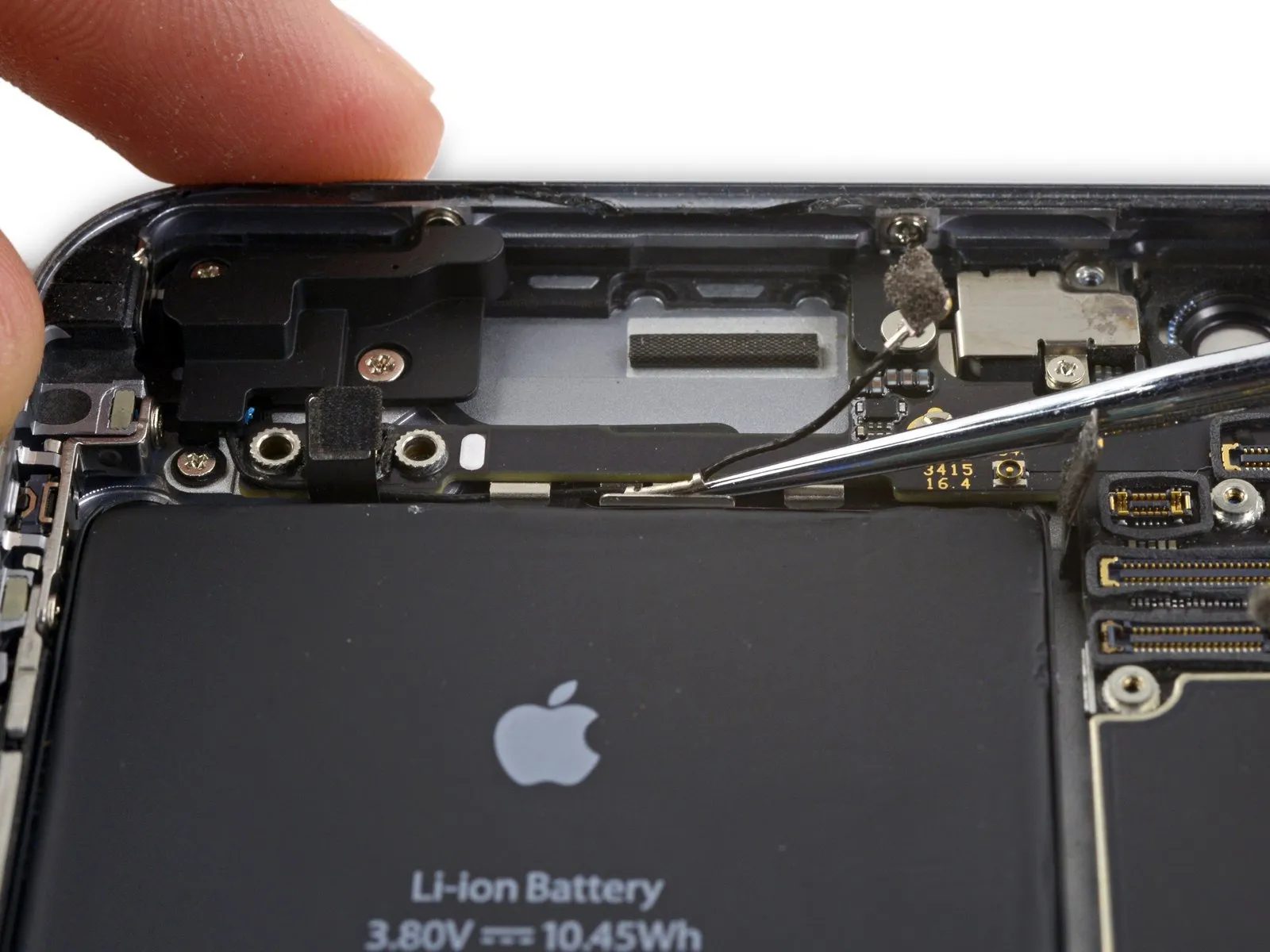
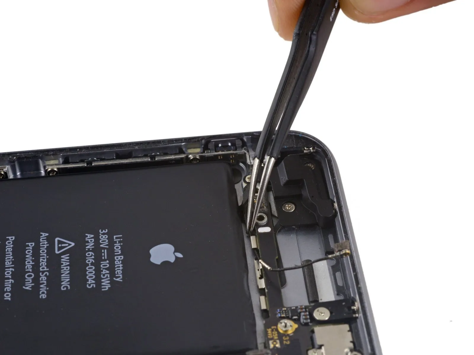
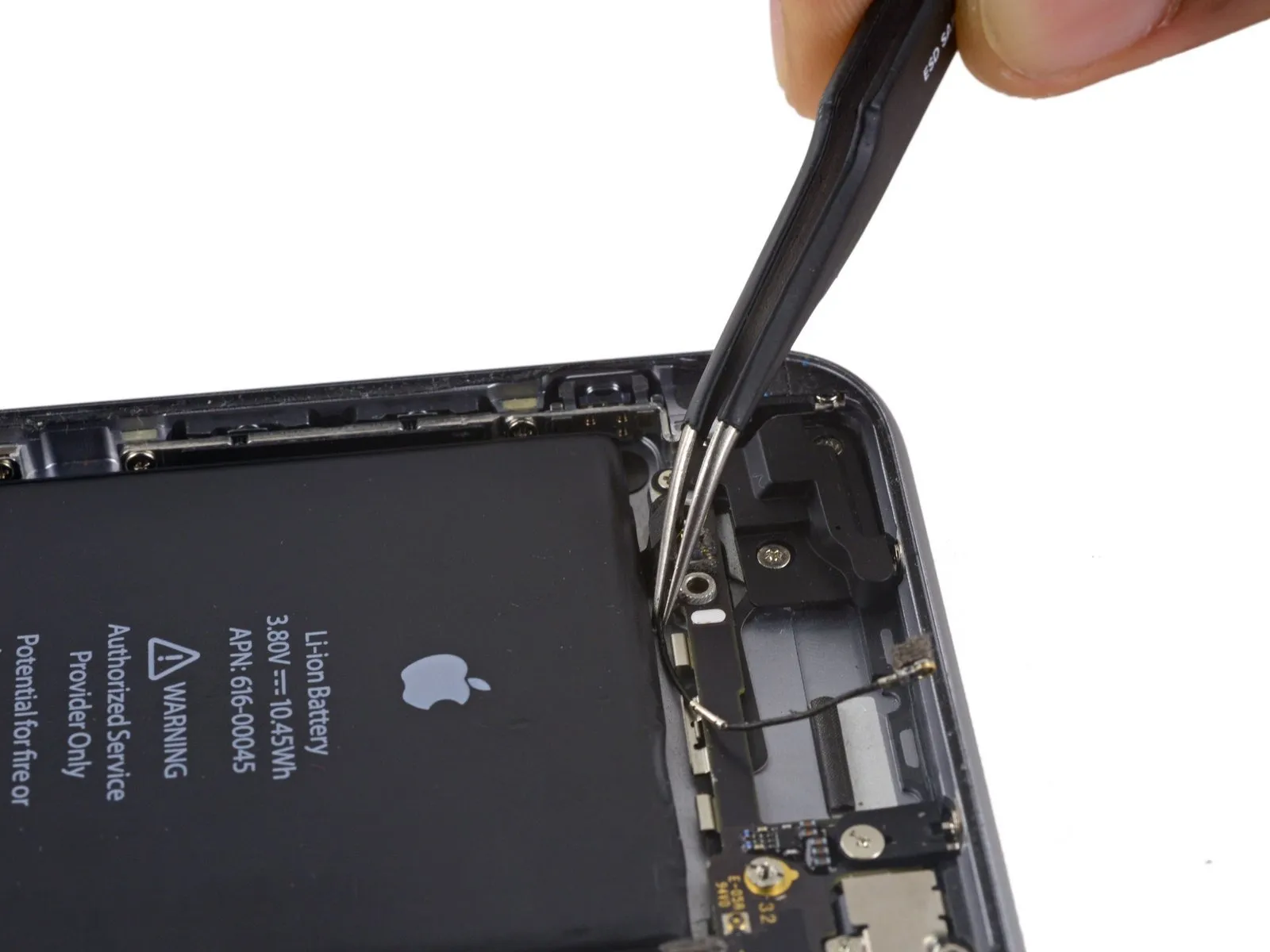
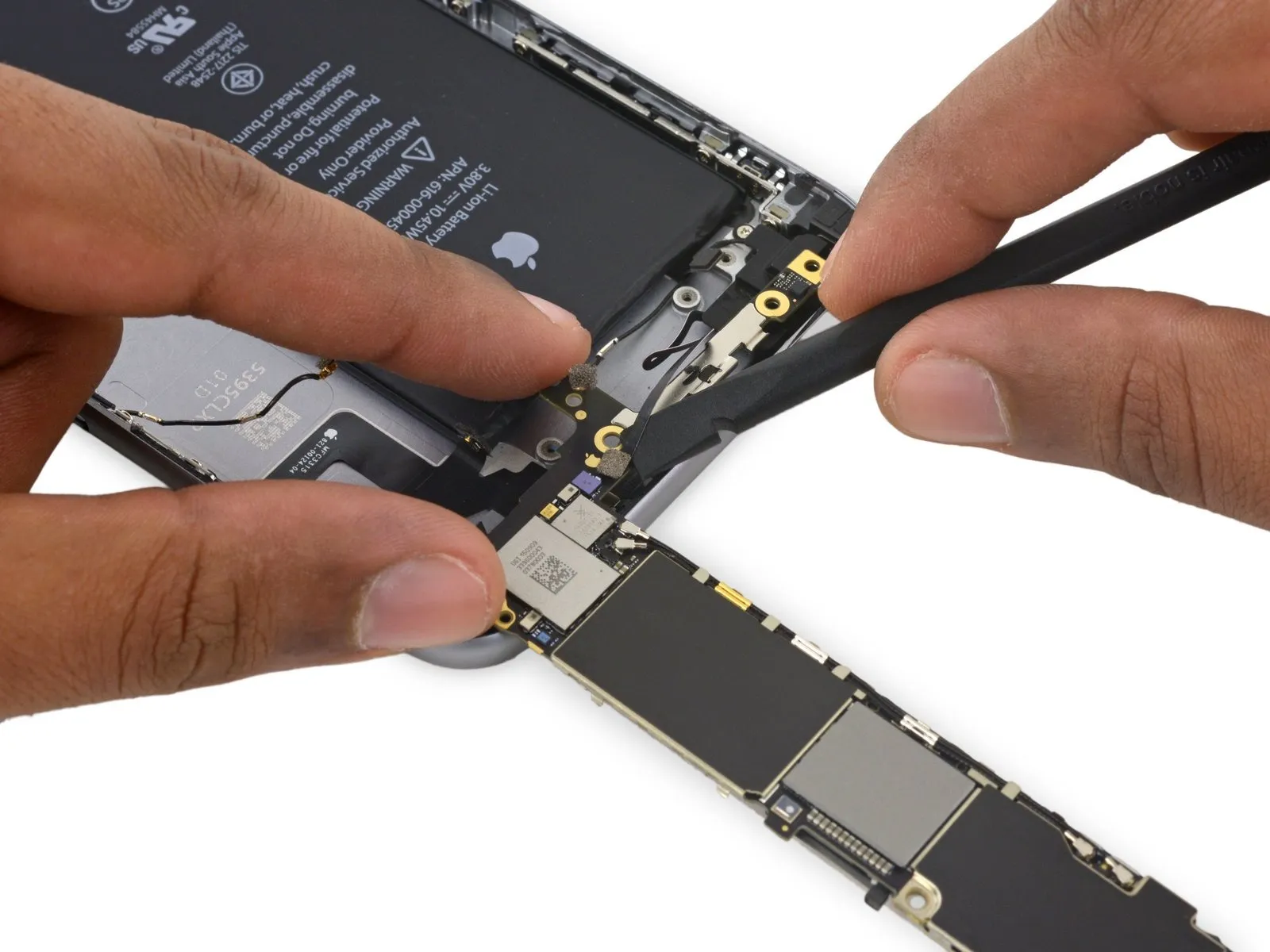
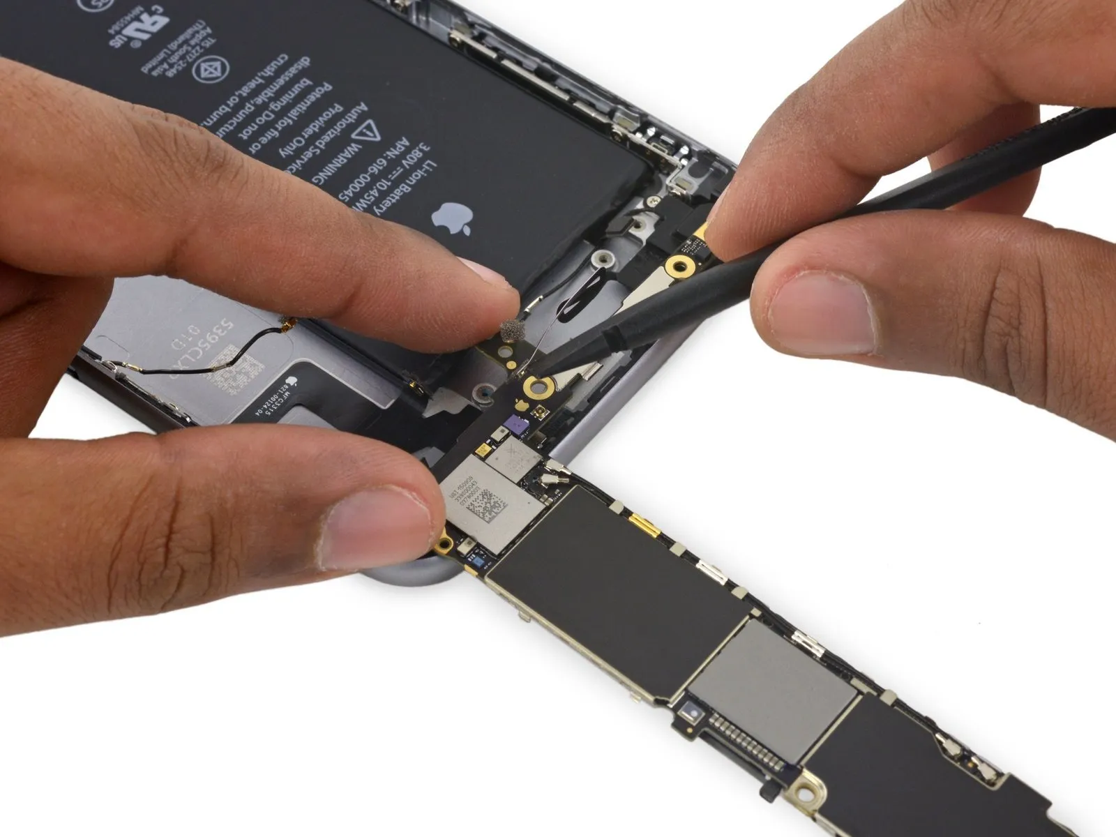
Step 40

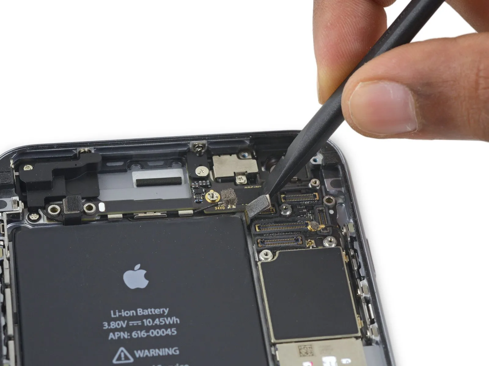
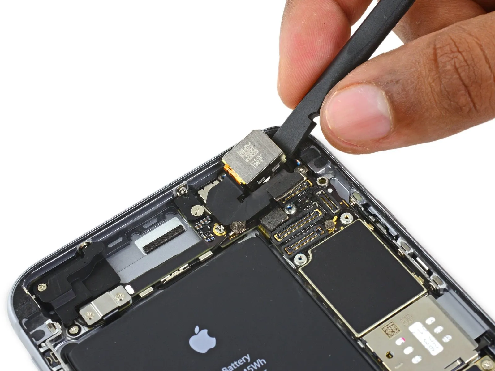
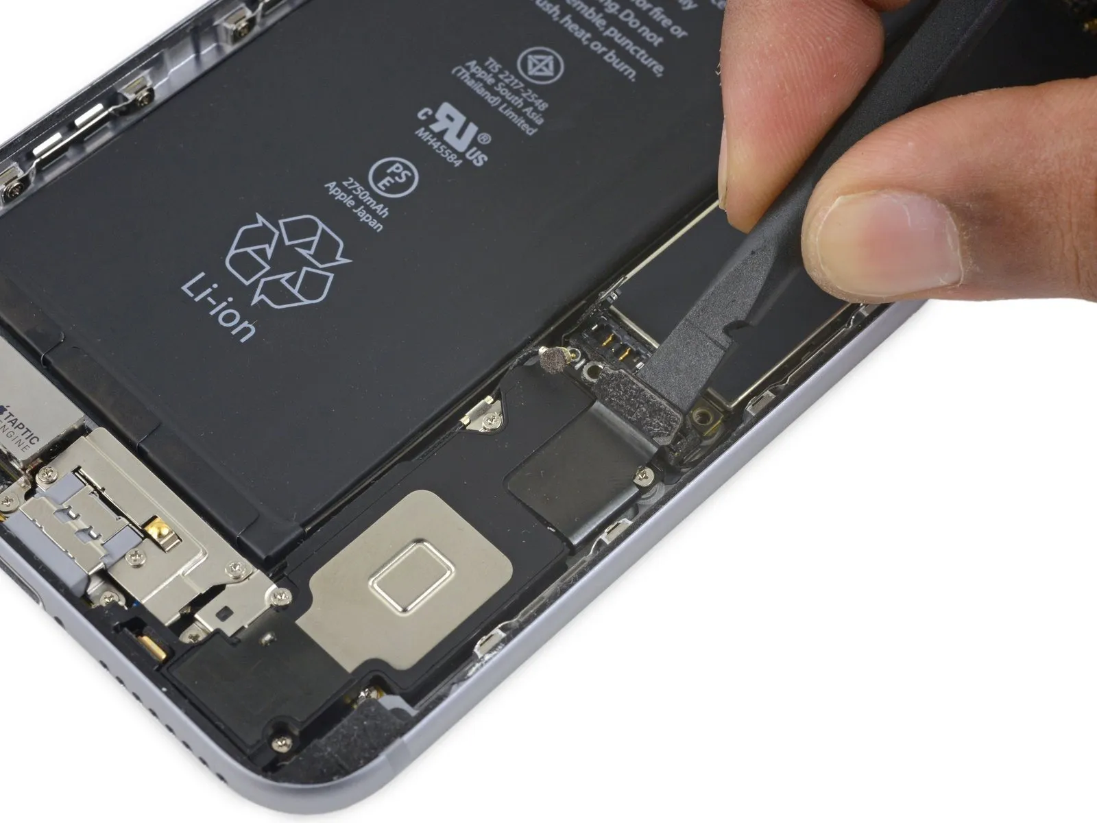
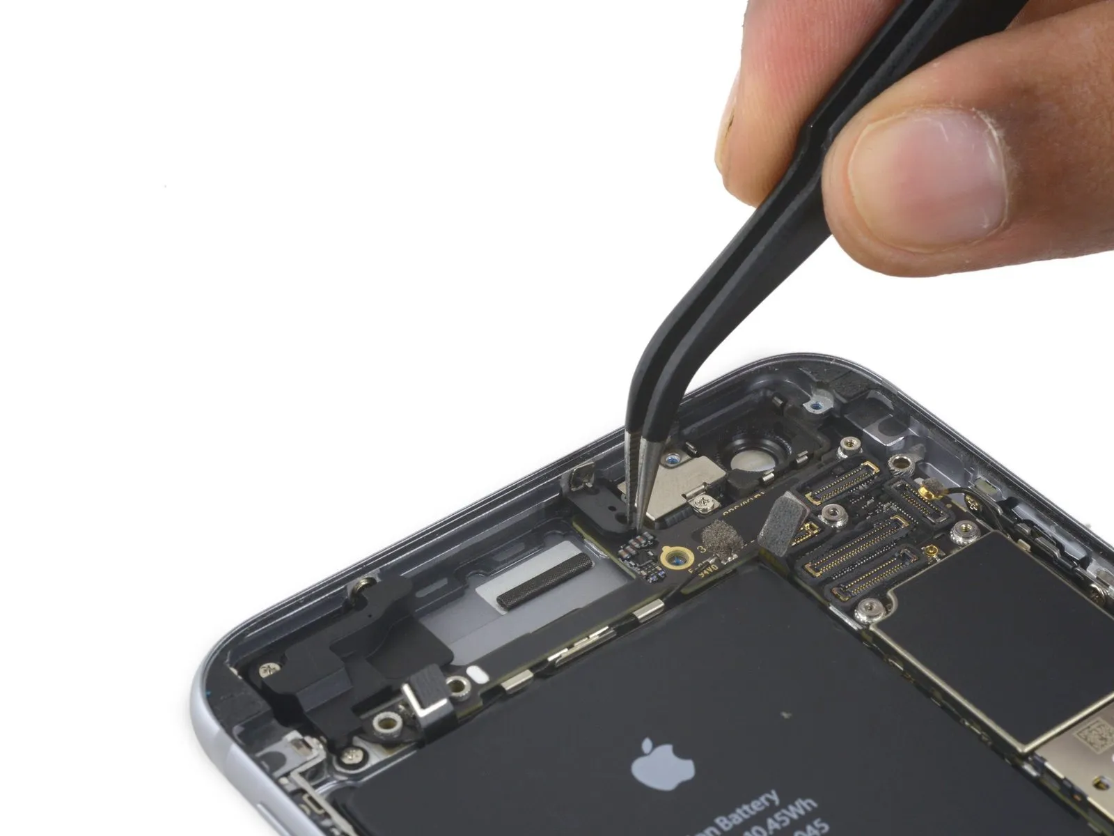
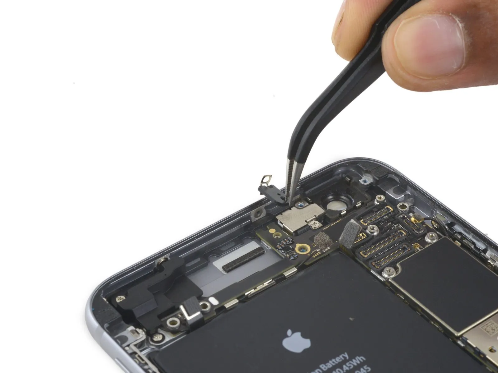
- Carefully detach theThe flexible cable connecting the power button to the device's circuit board.Carefully detach the component from its corresponding receptacle on the logic board.
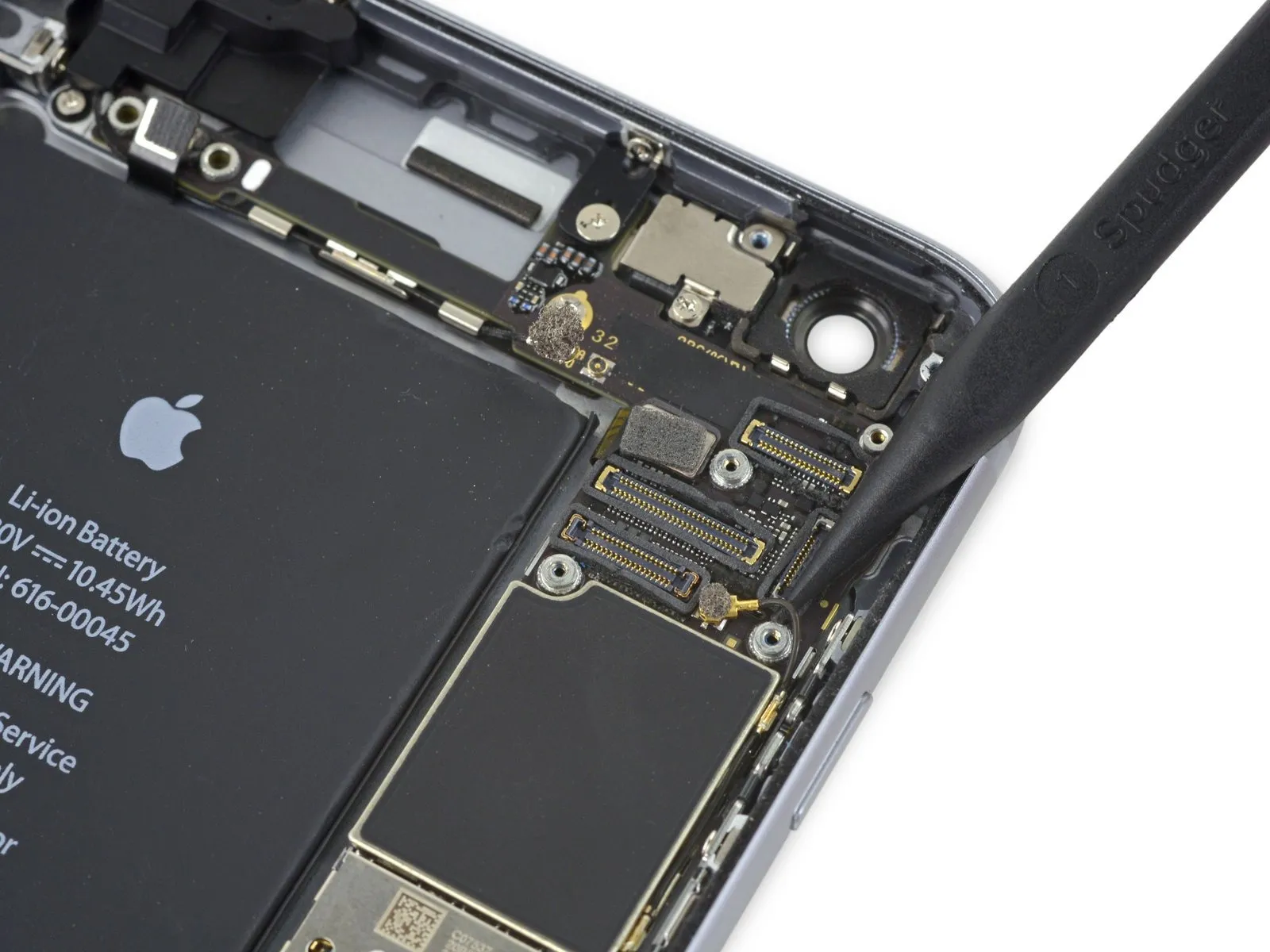
Step 41
Step 42
Step 43

Step 44

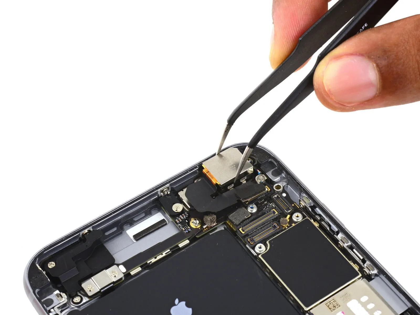
- Using the appropriate screwdriver, detach the listed fasteners.
Use a Phillips screwdriver to remove a single screw with a 1.3 mm head.
Use a Phillips screwdriver to remove a single screw with a 2.6 mm head.
A screw with a 2.2 mm diameter is needed. - To detach standoff screws, utilize a screwdriver or bit specifically designed for standoffs.
- If a dedicated tool isn't available, a small flathead screwdriver can be carefully substituted; however, exercise heightened awareness to prevent slippage and potential harm to nearby parts.
Step 45
Step 46
Step 47
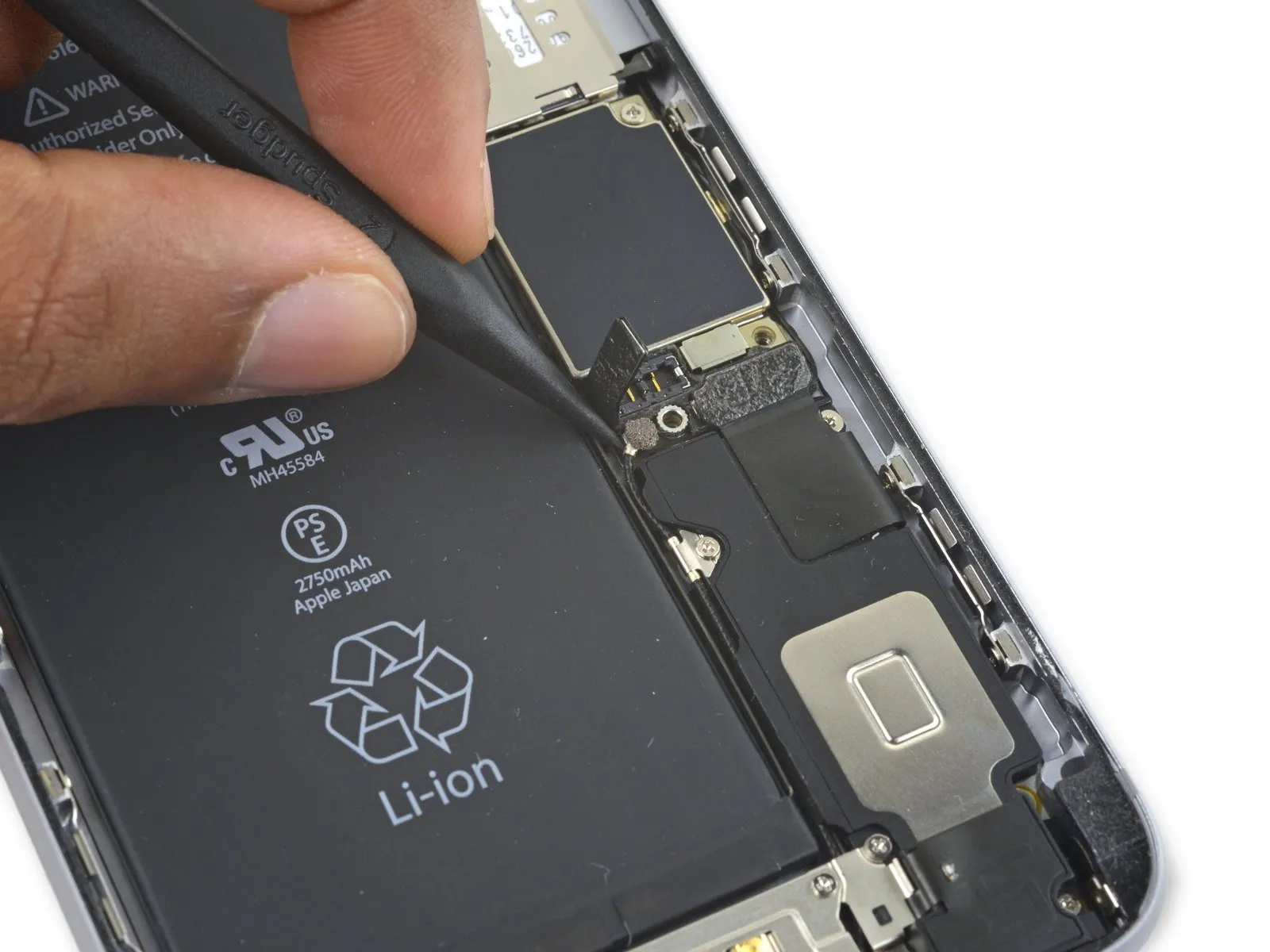
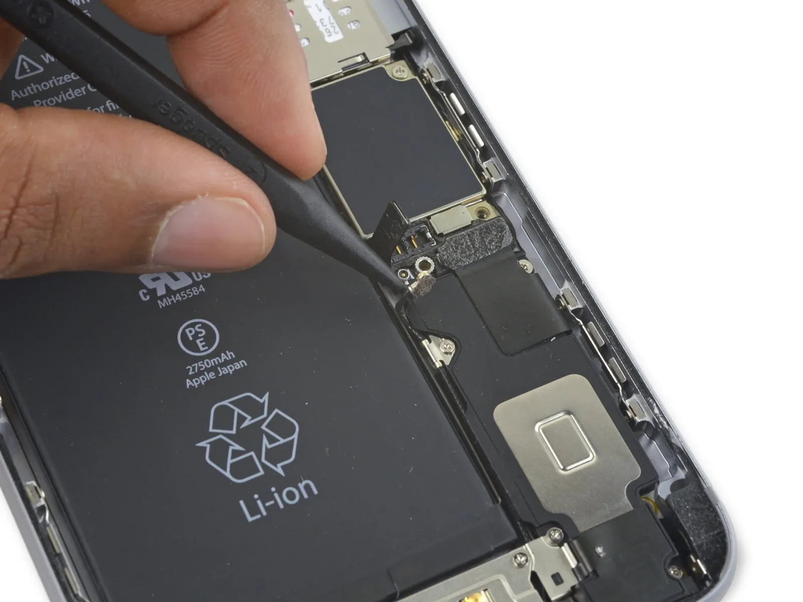
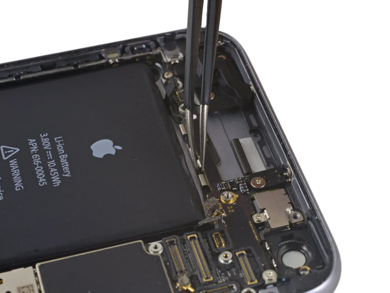
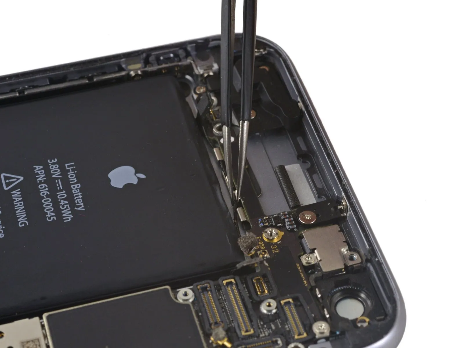
- Disconnect the cellular antenna cable from the second and third clips securing it to the logic board.
- Carefully insert the tip of the tool into.Use a plastic pry tool, often referred to as a spudger, to gently separate components.Carefully detach the cellular antenna cable from its securing clip on the central logic board, using gentle force.
- Avoid separation from the housing by applying force directly to the cable, as this will likely cause damage.
- To connect the cable to its corresponding socket on the logic board, position it initially over the board and then guide it below the audio control flex cable, referencing the visual guide in the first image for proper placement.
Step 48
Step 49


Step 50
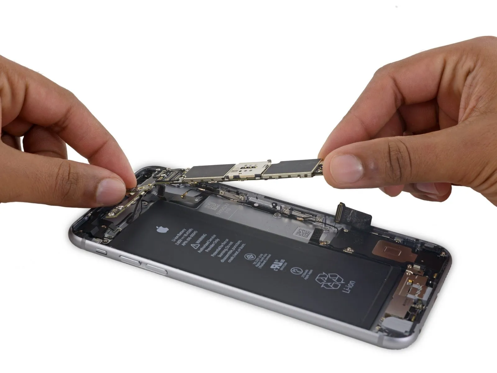
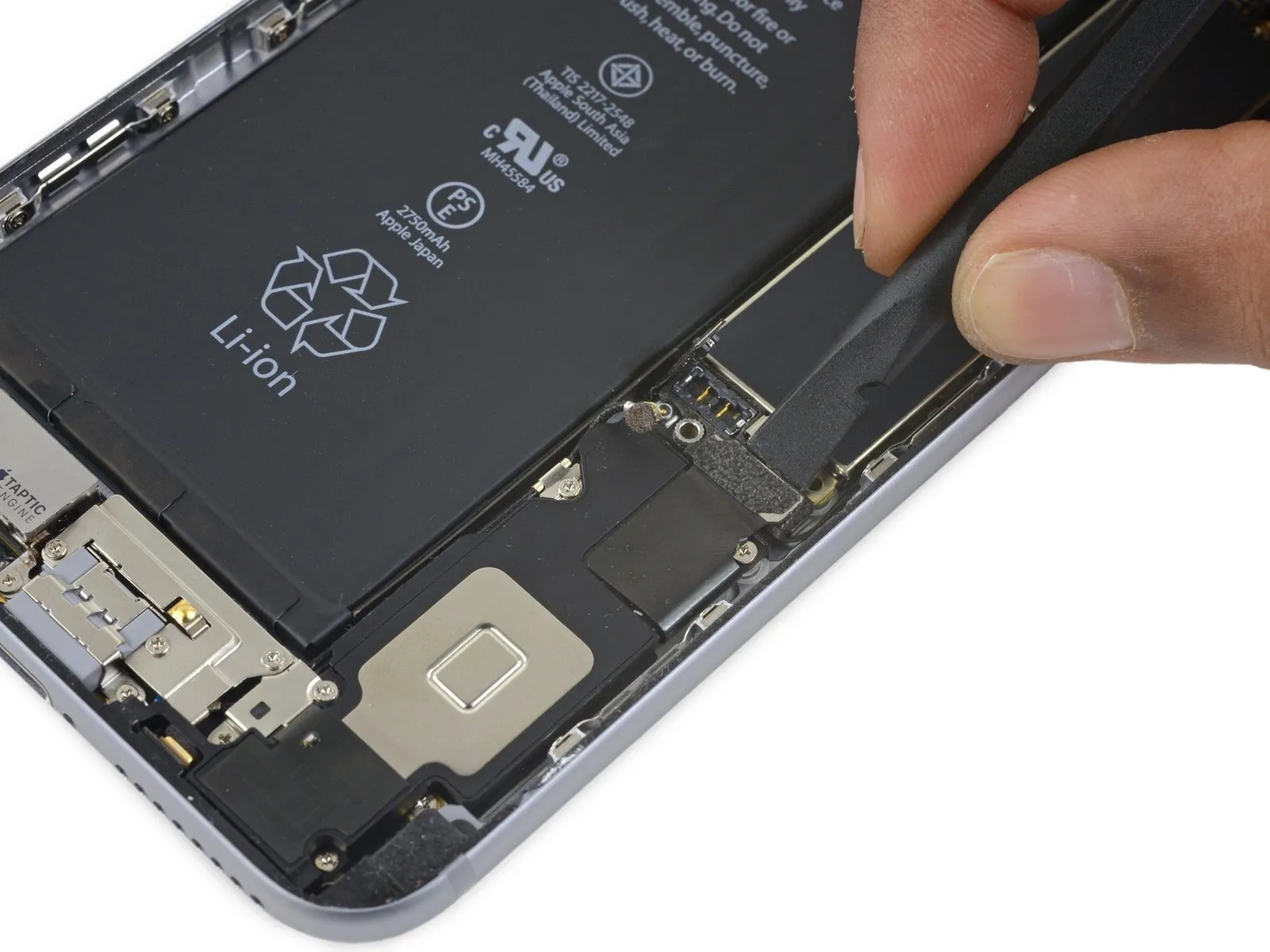
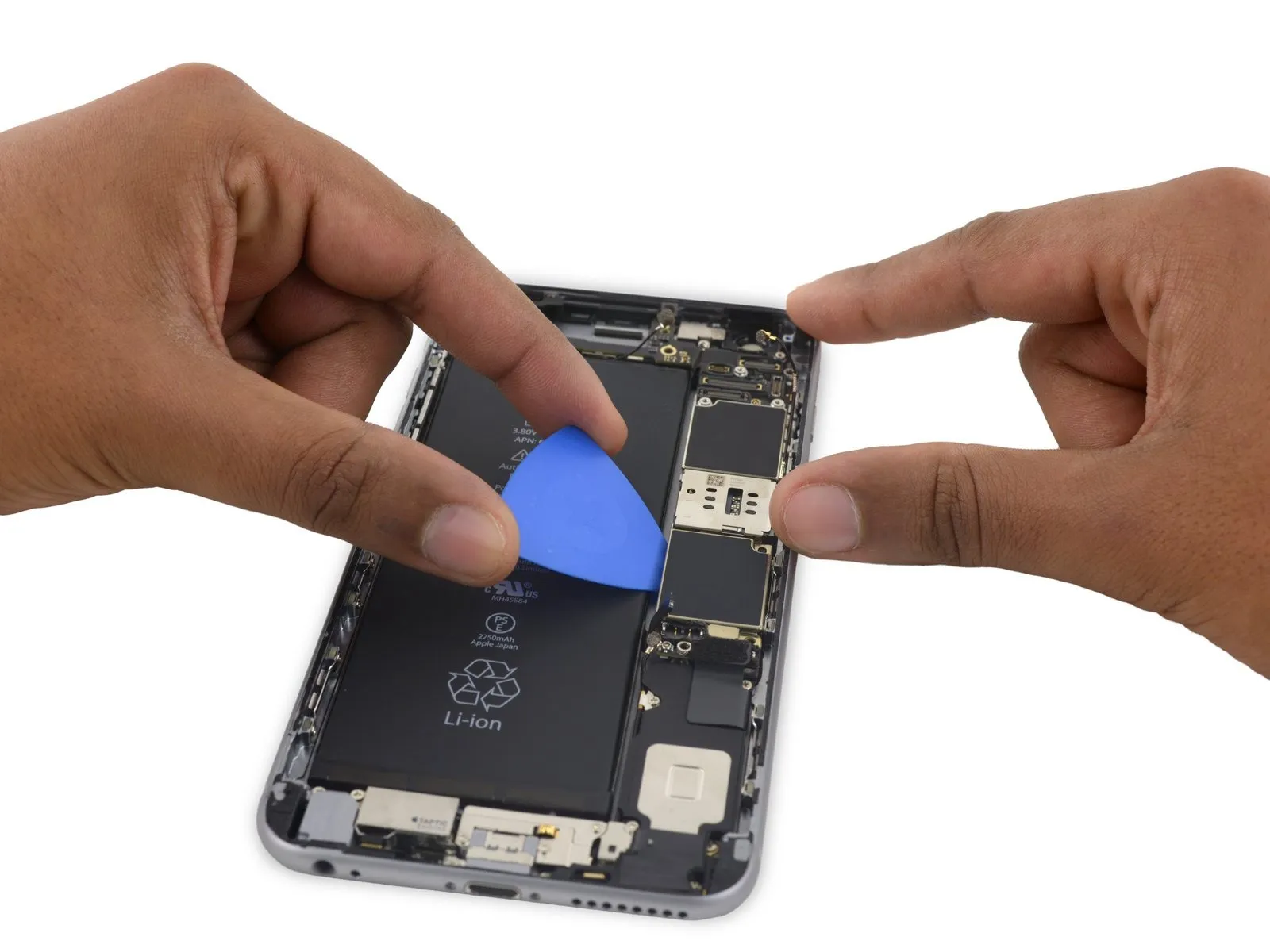
- To access the lone antenna connector, which is located on the bottom edge of the logic board close to the top, rotate the board so it stands upright.
- Disconnecting the Wi-Fi/Bluetooth antenna, which remains attached to the logic board's underside, prevents premature logic board removal.
Step 51
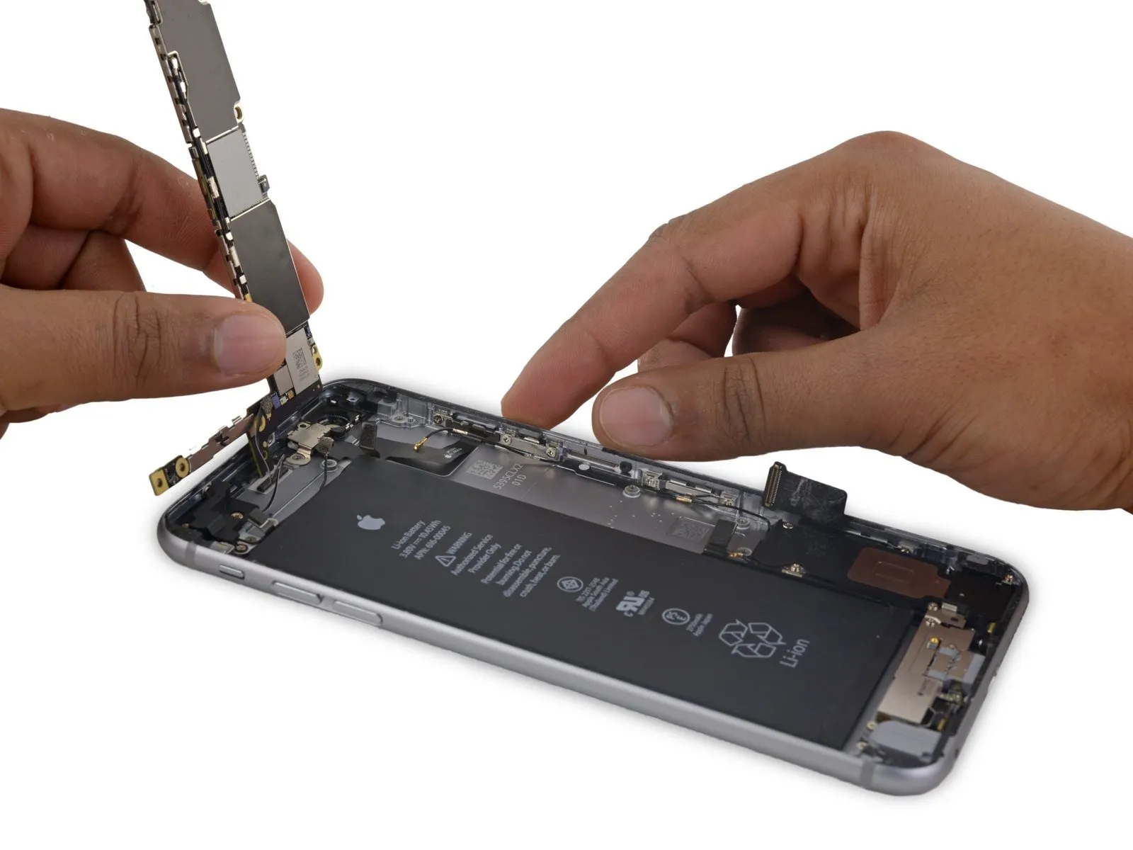
- Position the iPhone so the rear case supports the logic board, ensuring it rests securely with the component side facing upward.
Carefully separate the Wi-Fi/Bluetooth antenna cable from its connector on the logic board’s rear surface, employing the flat spudger tip.
Step 52

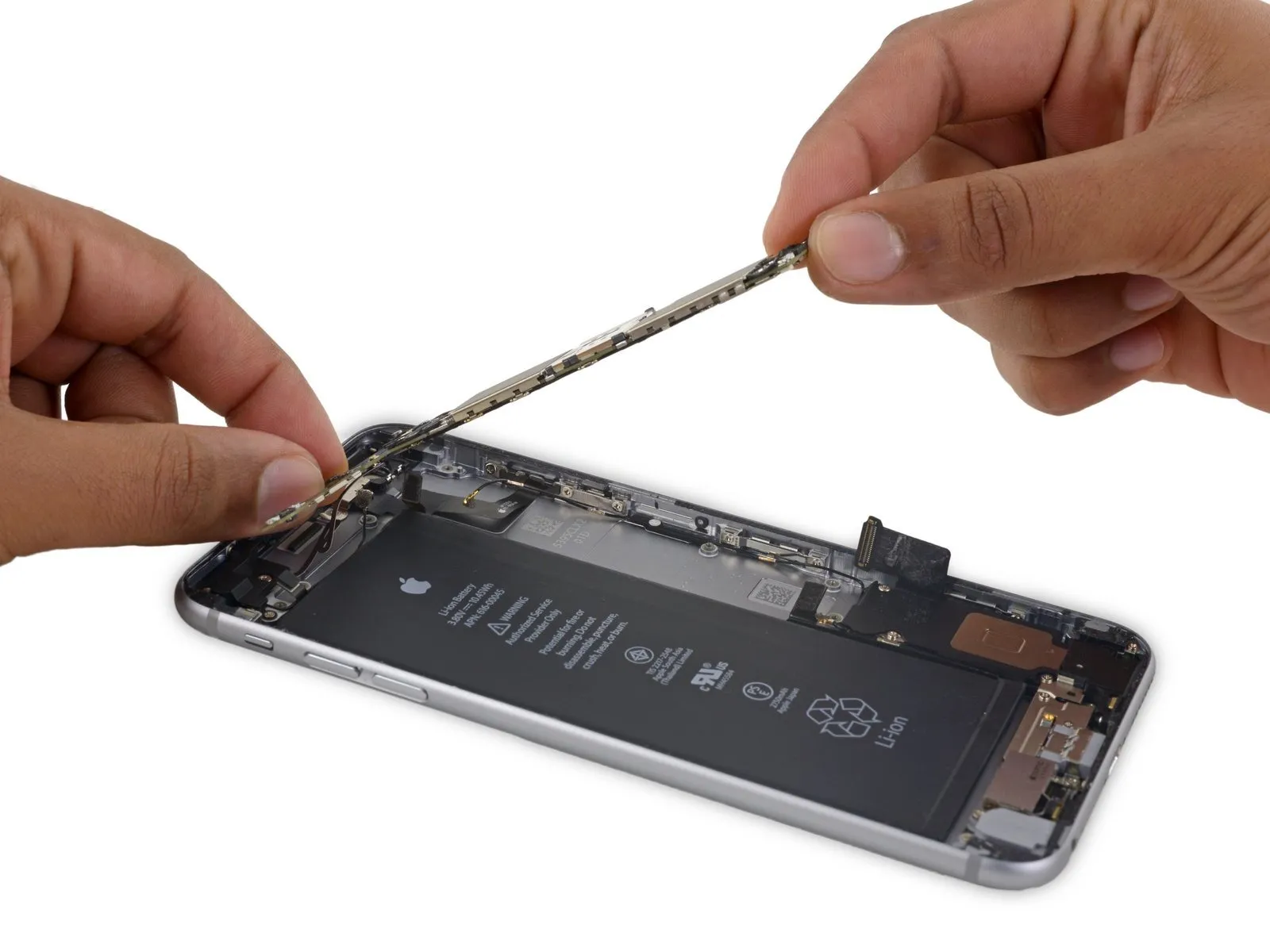
- Carefully detach the logic board from the device enclosure.
Step 53 | Power Button Cable Assembly
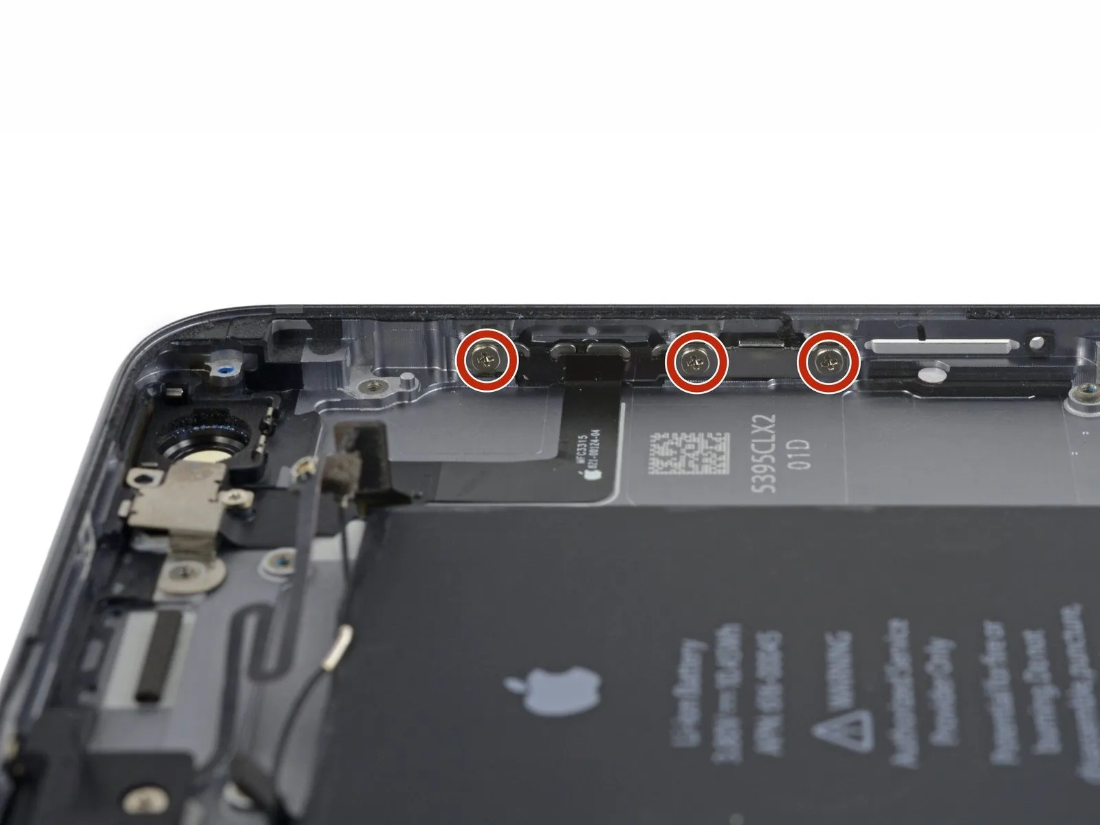

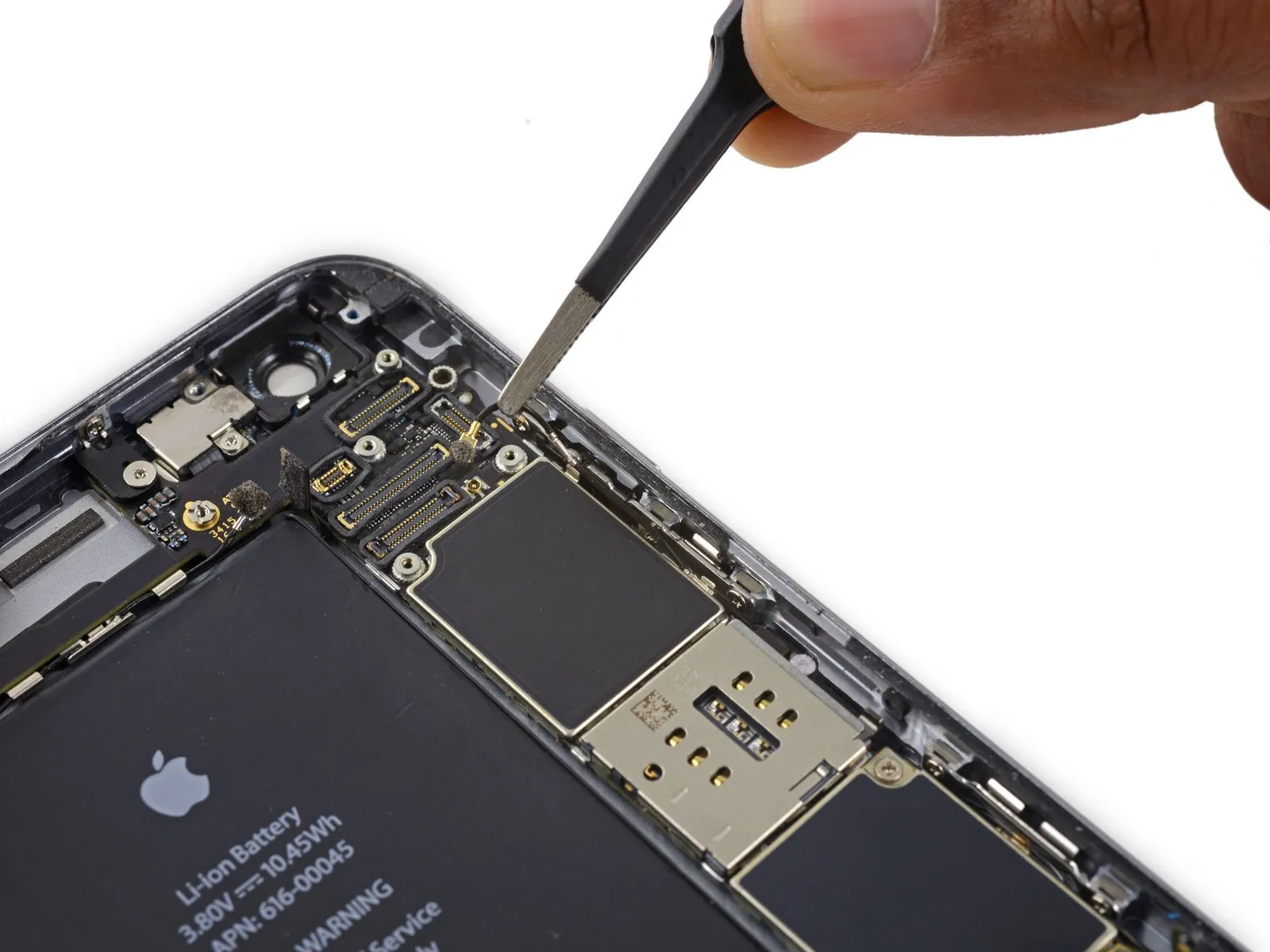
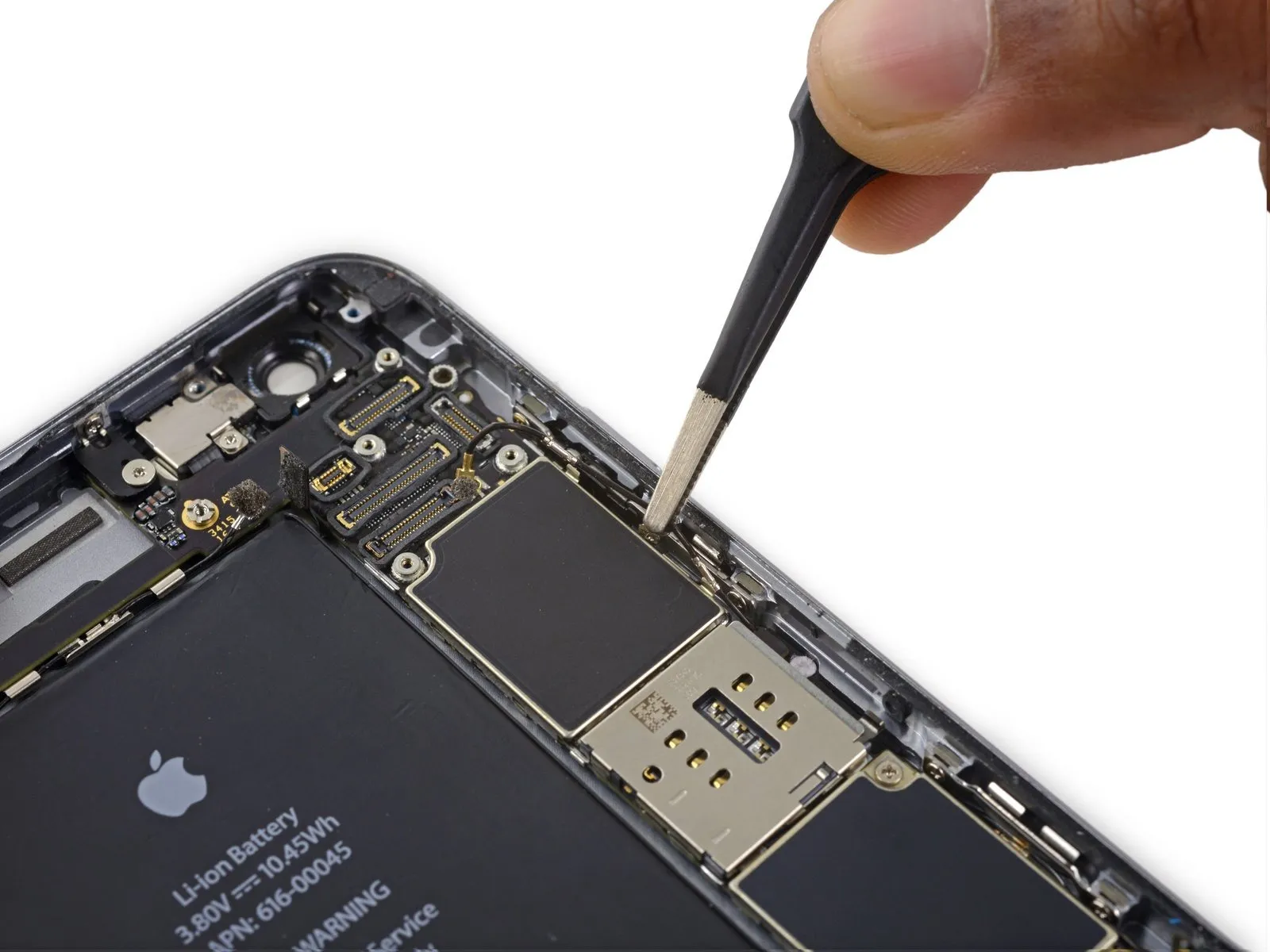
- Using a Phillips screwdriver, detach the four screws specified.
- Use a 2.0 mm drill bit three times.Secure the power button bracket with the screws.
- Use a Phillips screwdriver to remove a single screw with a 1.3 mm head.Position the component directly atop the flash and microphone mounting assembly.
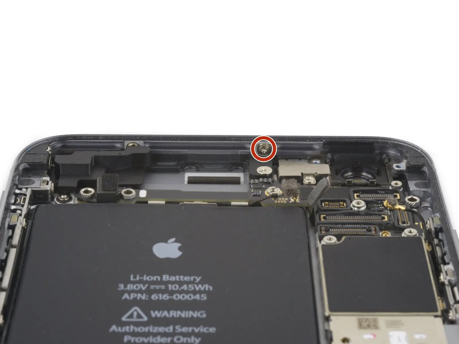
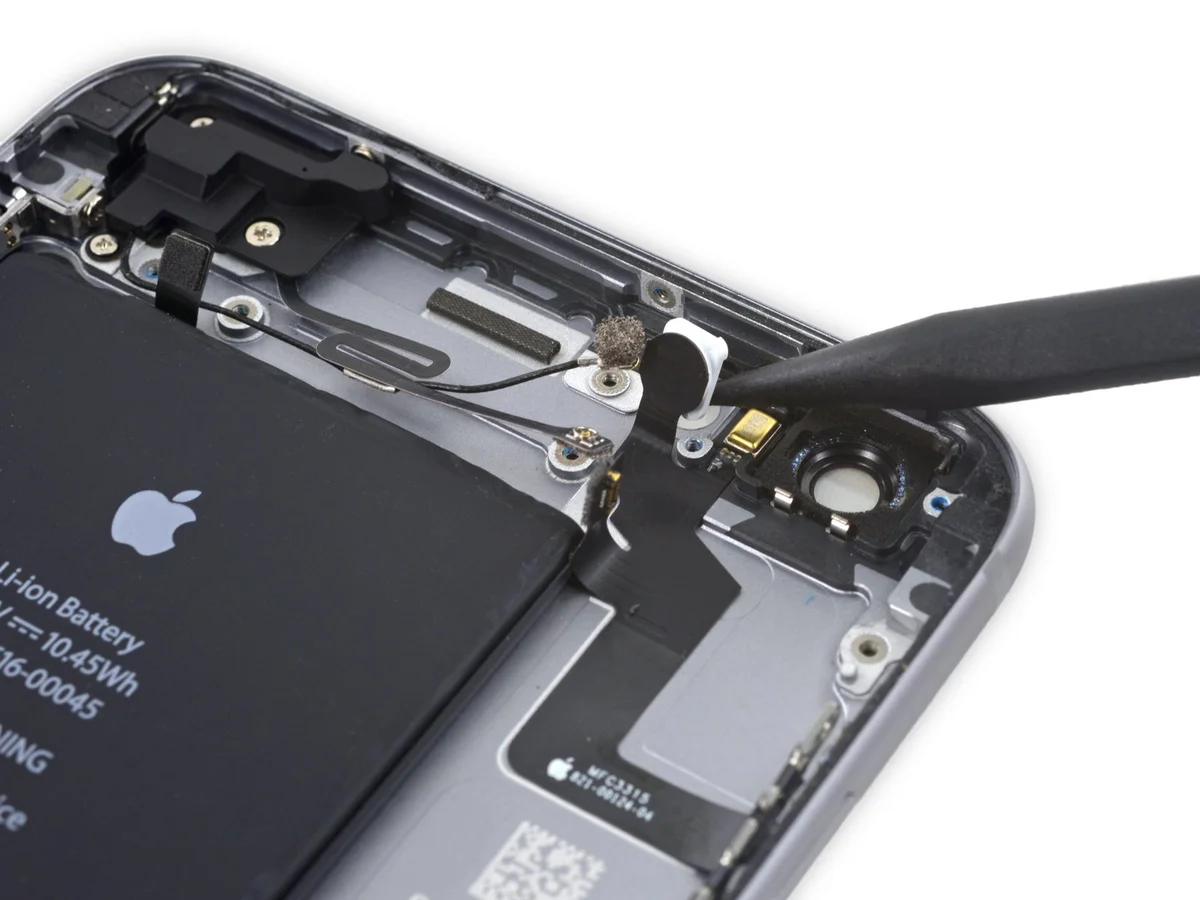
Step 54


- Carefully detach the component, ensuring no damage occurs.Secure the flash or microphone using the bracket..
Step 55

- Carefully pry the component up with the tip of a spudger.Briefly expose the component to a high-voltage pulse using a dedicated programming device to electrically erase and rewrite its memory contents.Carefully remove the component from its enclosure located within the back cover.
Step 56
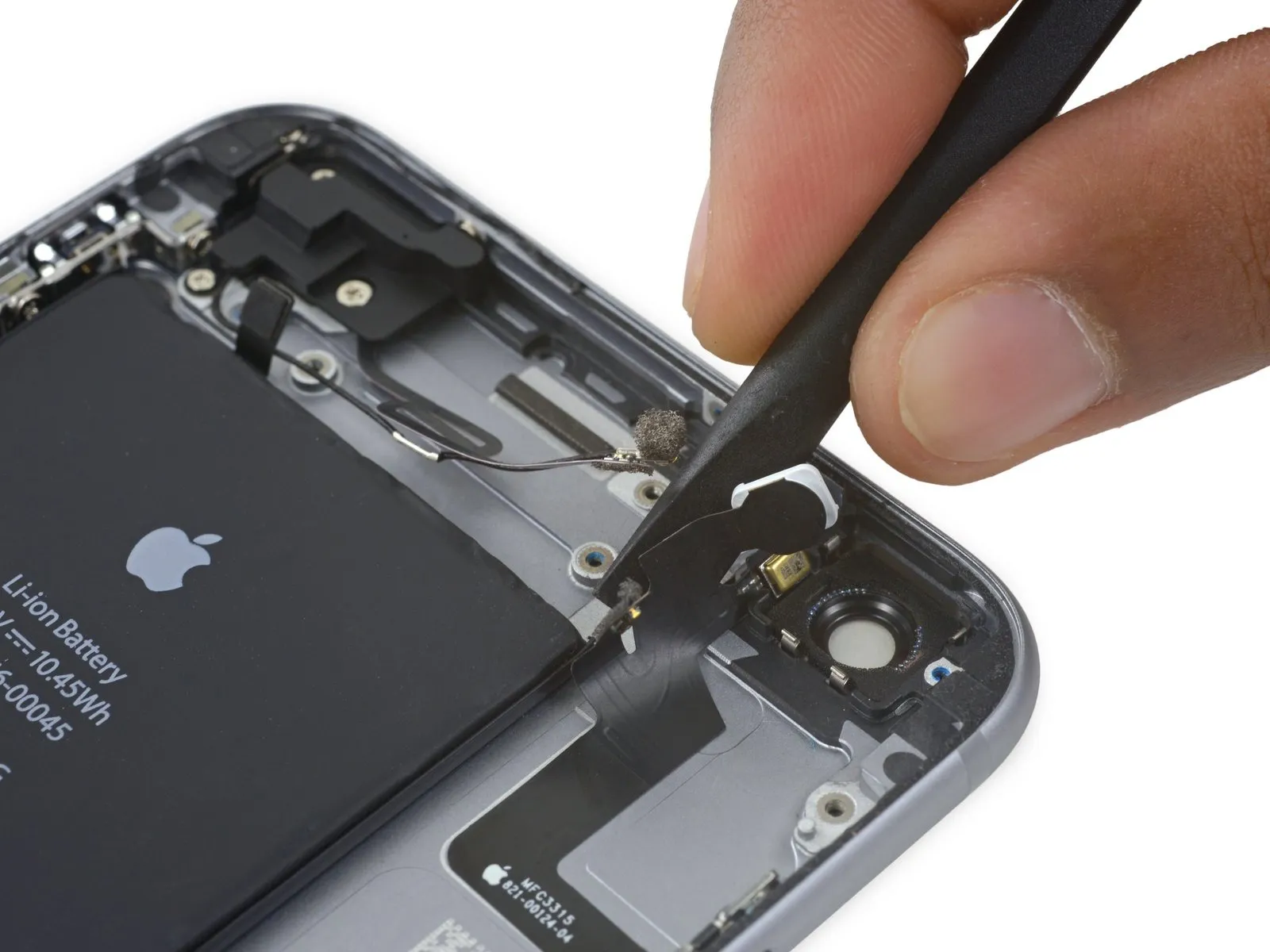
Step 57
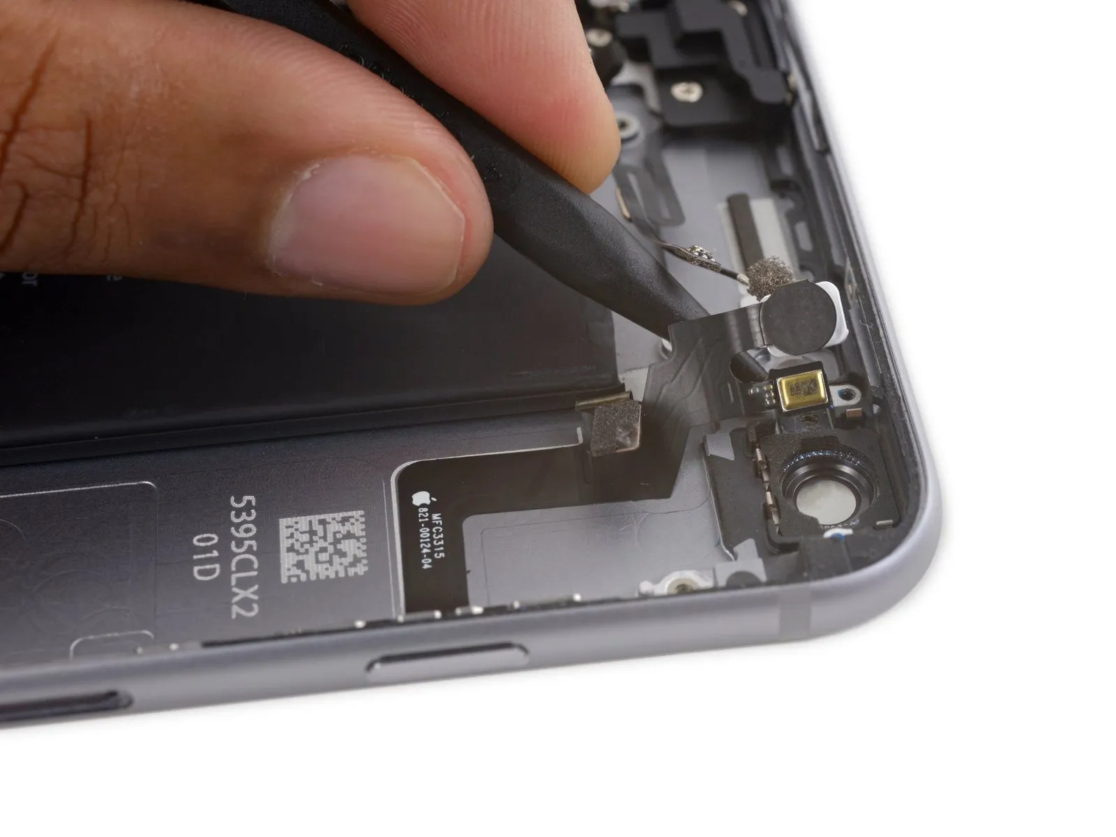
- Carefully guide the pointed end of aUse a plastic pry tool, often referred to as a spudger.Carefully separate the flex cable from the rear case by gently lifting it away from beneath the microphone assembly.
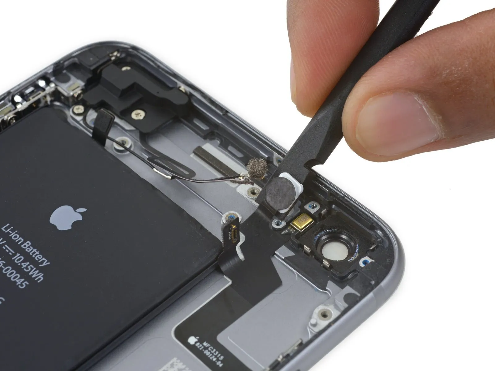
Step 58
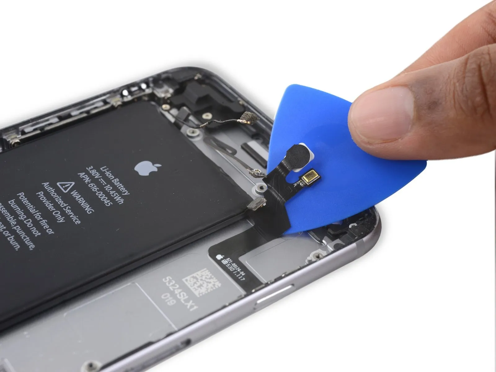


- Using an opening pick, carefully separate the power button flex cable from the rear case by gently levering it away.
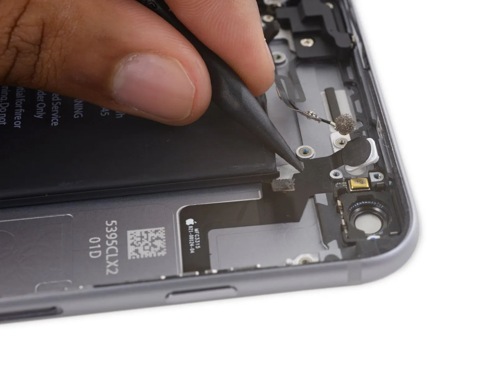
Step 59
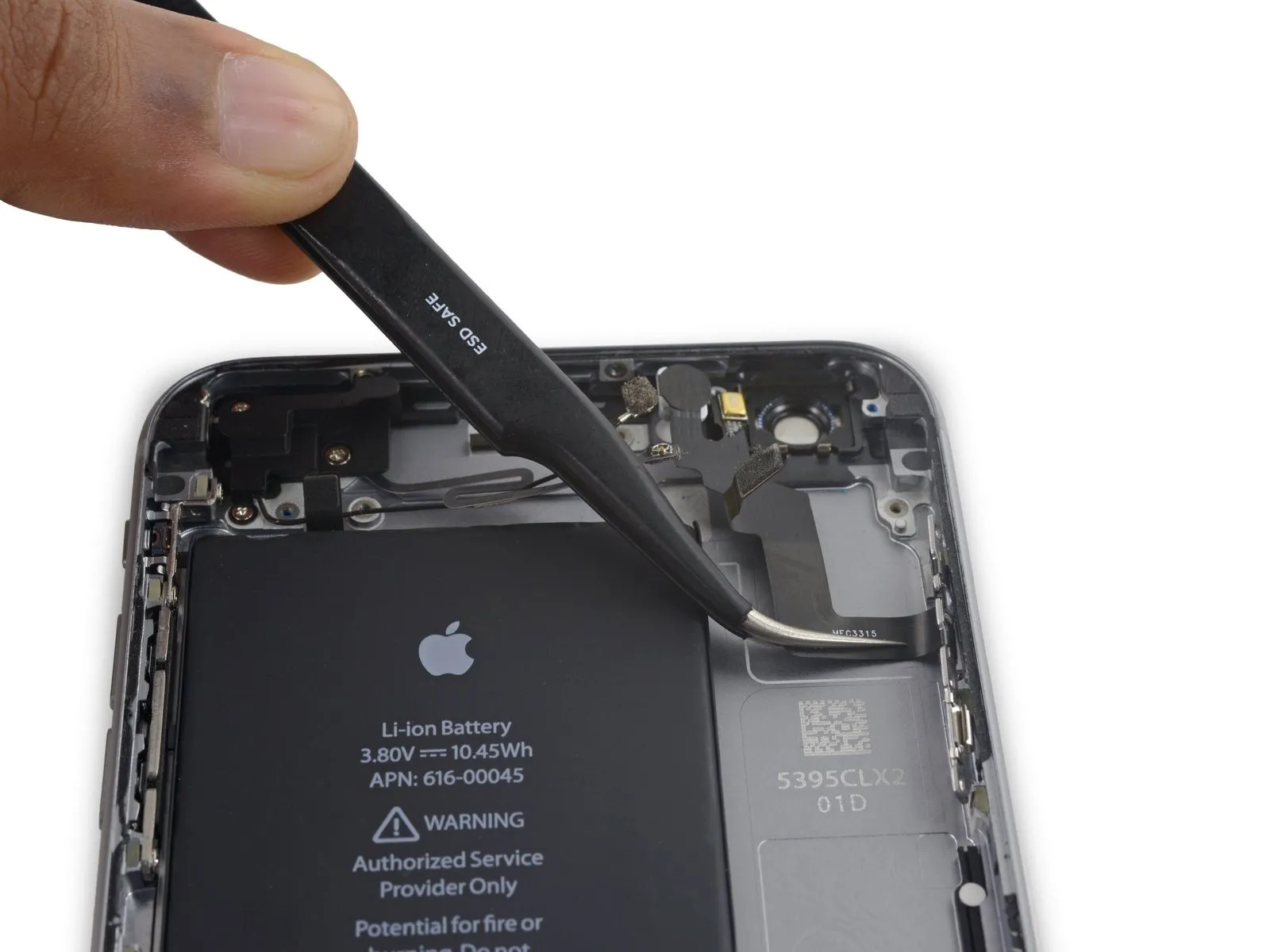

- Carefully disconnect the flex cable that connects to the power button.
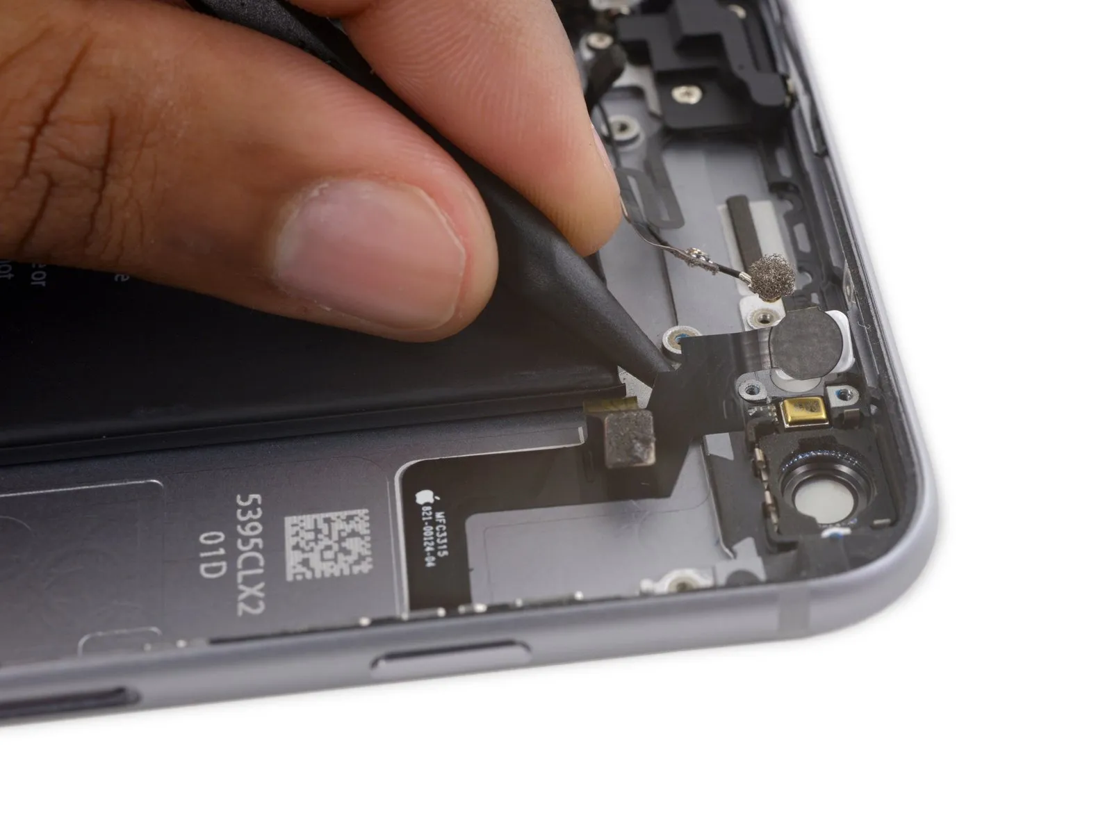
Step 60 | Power Button Cover
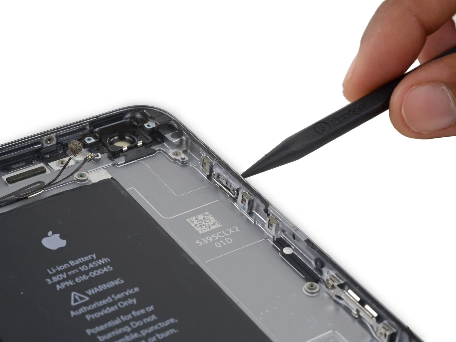
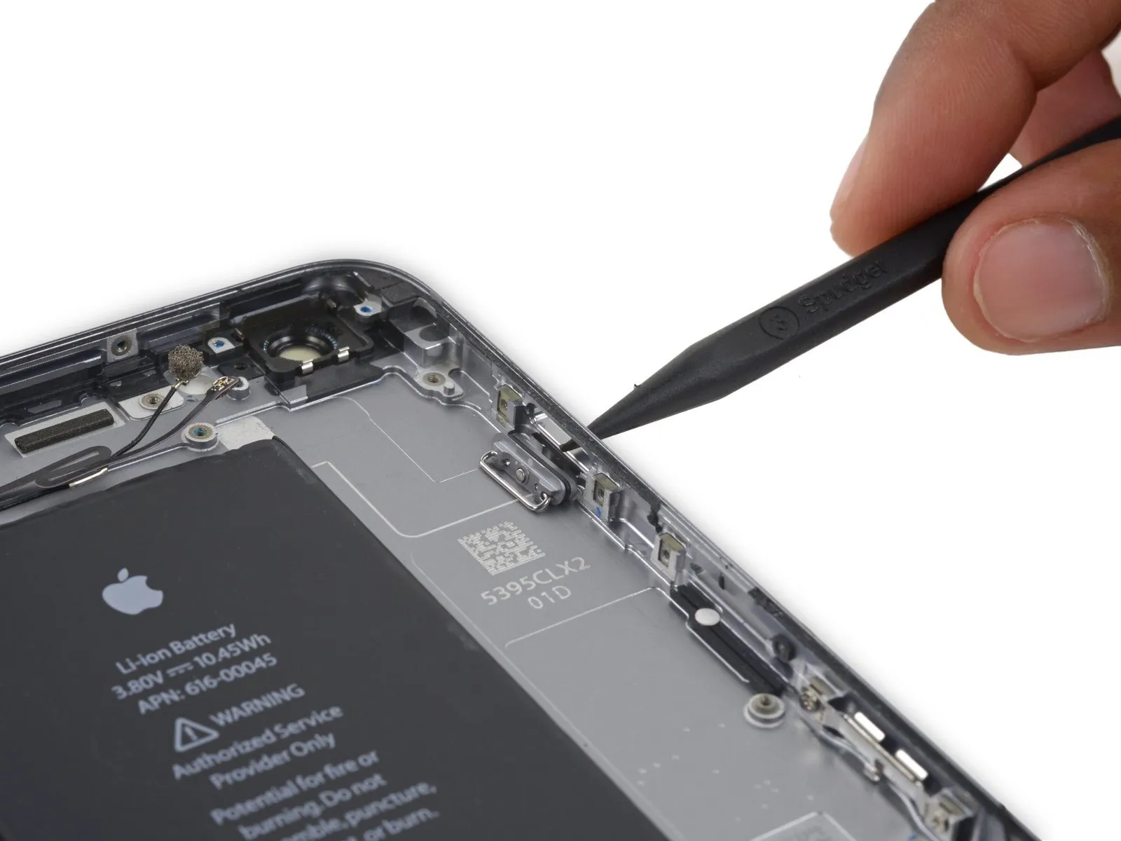
- Using slight pressure, disengage the power button cover from its mounting within the rear case.
Step 61
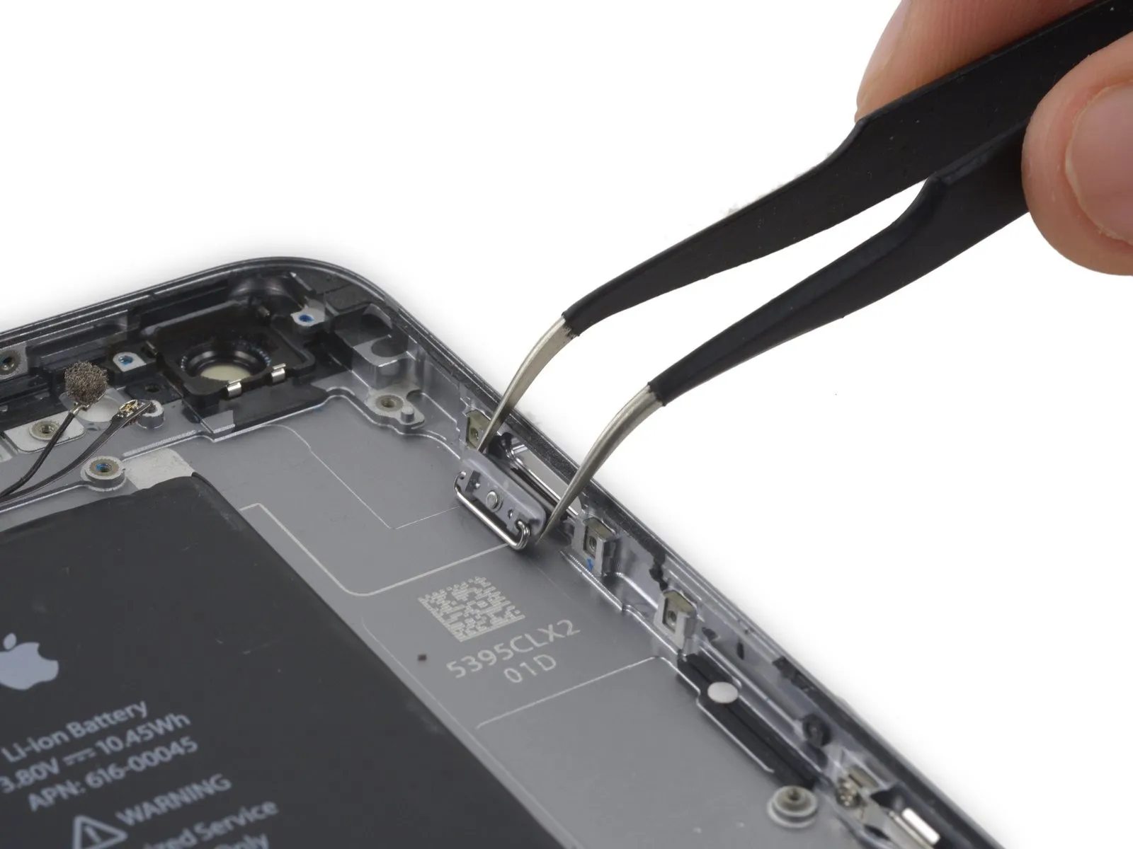
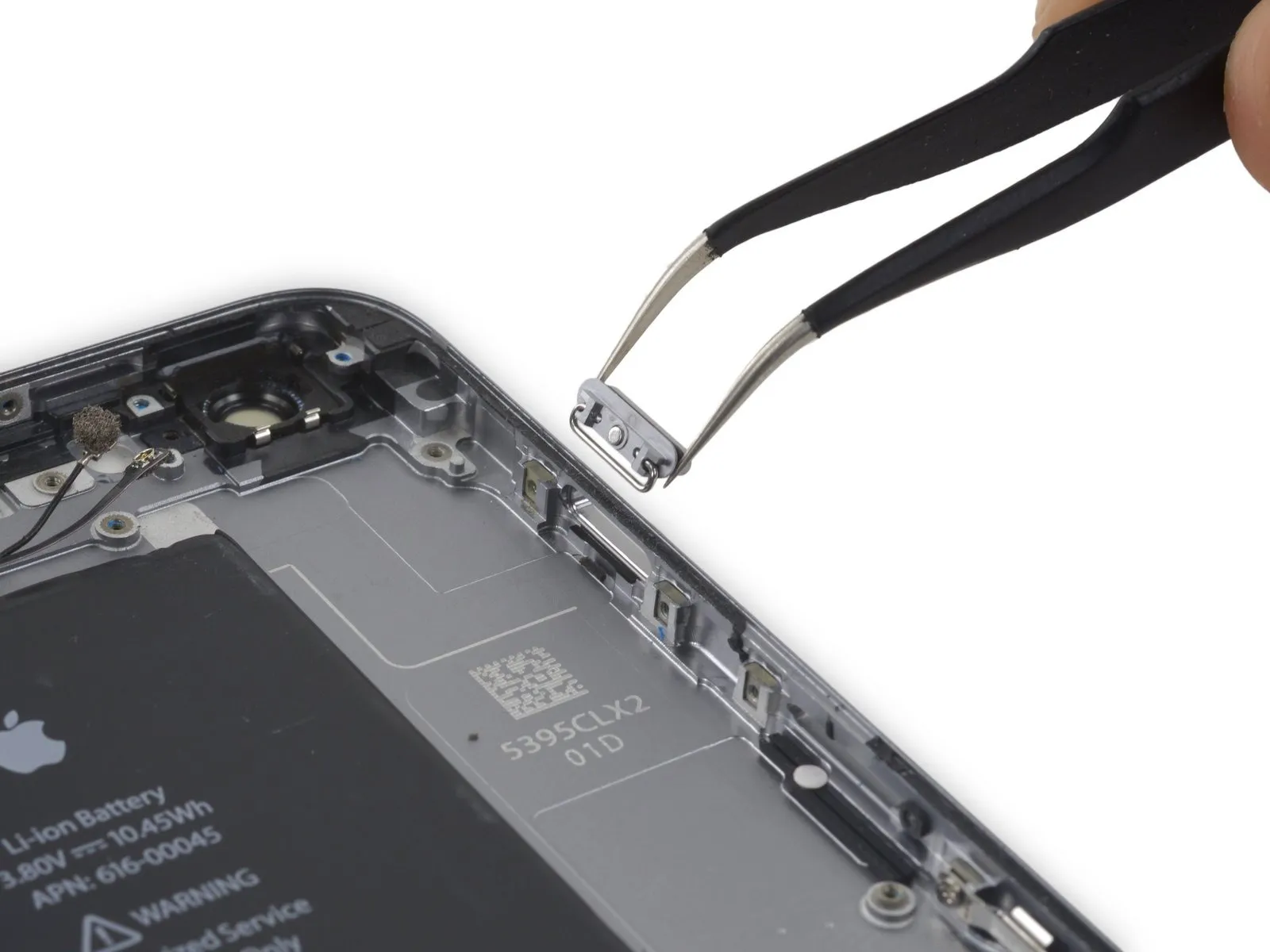
- Carefully detach the component, ensuring all original specifications and dimensions are maintained.Affix a protective cap over the push button..