iPhone 6s Plus LCD and Digitizer Replacement
To simplify the repair process, utilize our specialized repair kit and adhere to this condensed procedure for a complete iPhone screen replacement.
- This detailed instruction set is intended for experienced repair technicians.This guide facilitates the replacement of solely the iPhone 6s Plus LCD and digitizer assembly, commonly referred to as the bare "front panel". Prior to final installation, several components must be carefully moved from the original screen to the replacement—specifically, the front-facing camera, earpiece speaker, LCD shield plate, and the home button assembly.
- Regardless of the display repair being performed, transferring the original home button to the new display is crucial for the proper operation of Touch ID, the fingerprint recognition system.
This guide can also be consulted for the replacement of these additional components:
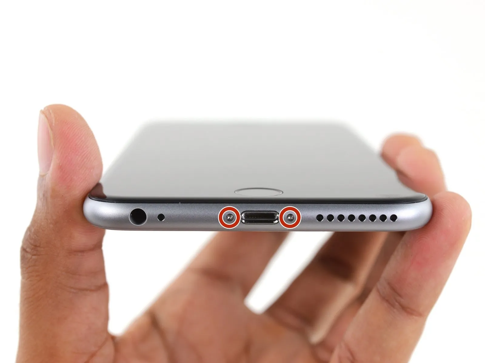
Step 1 | Pentalobe Screws
- To prevent potential hazards, ensure the iPhone's battery level is reduced to less than 25% prior to any disassembly procedures.A fully charged lithium-ion batteryposes a fire risk and/or potential for explosion if it experiences accidental physical damage.
- Deactivate the iPhone by powering it down completely before commencing the disassembly process.
- Begin the disassembly by eliminating the pair of 3.4 mm Pentalobe screws located on both sides of the Lightning connector.
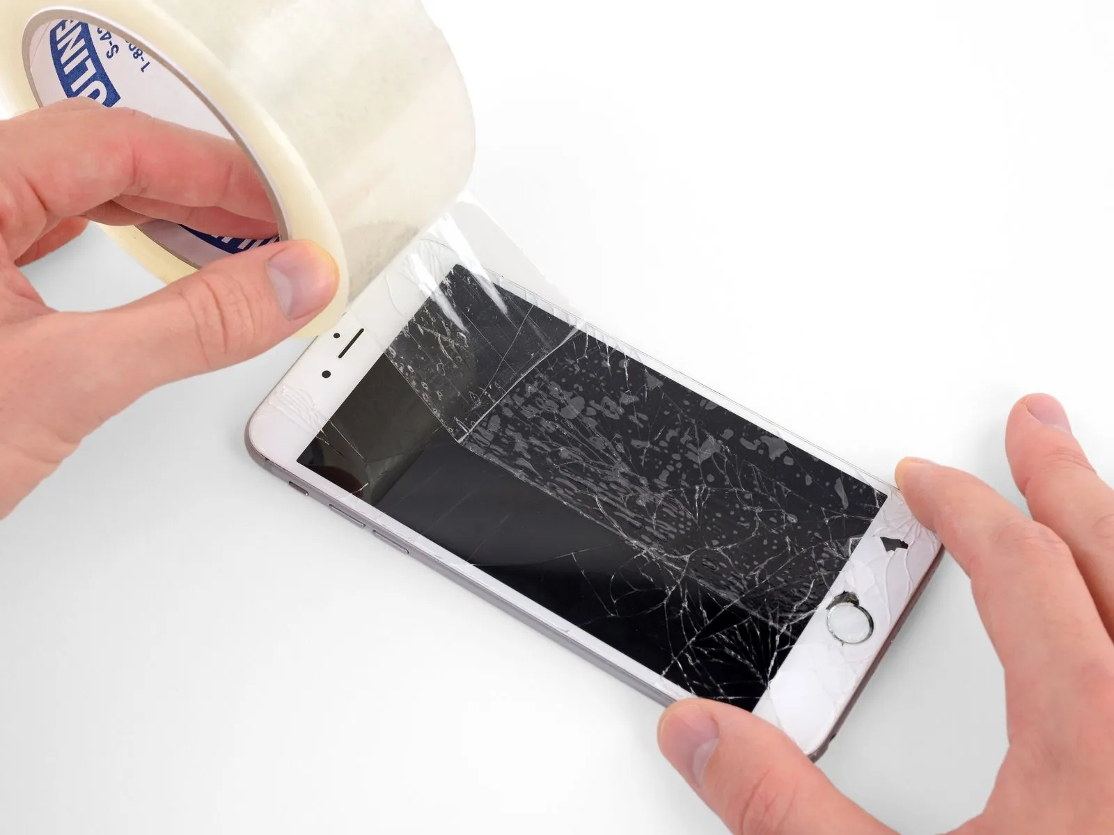
Step 2 | Taping Over The Display
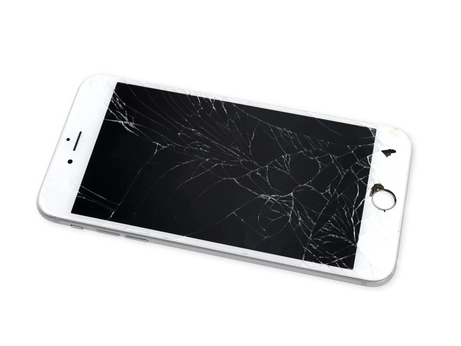

- To mitigate the risk of additional shattering and potential injury while performing the repair, secure any cracked display glass with tape.
- Apply multiple, overlapping layers of transparent packing tape across the iPhone's screen surface, ensuring complete coverage; this containment method minimizes glass shard dispersal and reinforces the display's structure during the prying and lifting procedures.
- Always utilize safety glasses to shield your eyes from any glass fragments that may become dislodged throughout the repair process.
- Should the fractured glass impede the adhesion of a suction cup in subsequent steps, consider creating a handle from a robust tape (like duct tape) to facilitate display lifting.
Step 3 | Anti-Clamp instructions


The following two procedures showcase the Anti-Clamp, a specialized tool developed to simplify the initial opening process. Should you choose not to utilize the Anti-Clamp, proceed past three steps to access an alternative approach.
Detailed guidance regarding the Anti-Clamp's operation can be found in this separate instructional document.
- To release the Anti-Clamp's gripping arms, retract the blue handle towards the rear.
- Carefully position the arms across either the left or right side of your iPhone.
- Place the suction cups close to the lower edge of the iPhone, situated directly above the home button—one on the front face and one on the rear.
- Apply pressure by compressing the cups together to establish a secure suction on the intended surface.
- In situations where the iPhone's surface exhibits excessive slipperiness, hindering the Anti-Clamp's ability to maintain a hold, applying adhesive tape can provide a more textured interface.
Step 4


- To secure the arms, advance the blue handle in a forward direction.
- Rotate the handle through a complete circle, equivalent to 360 degrees, or until the suction cups begin to deform. It is essential that the suction cups maintain their parallel orientation. Should the suction cups start to deviate from their alignment, slightly reduce the suction and reposition the arms.
- Once the Anti-Clamp has generated a noticeable separation, slide an opening pick beneath the display screen.
- Should the Anti-Clamp fail to produce an adequate gap, incrementally rotate the handle by 90 degrees. Avoid exceeding a quarter-turn rotation at any point, and allow several seconds to elapse between each adjustment. Permit the Anti-Clamp and the passage of time to facilitate the separation.
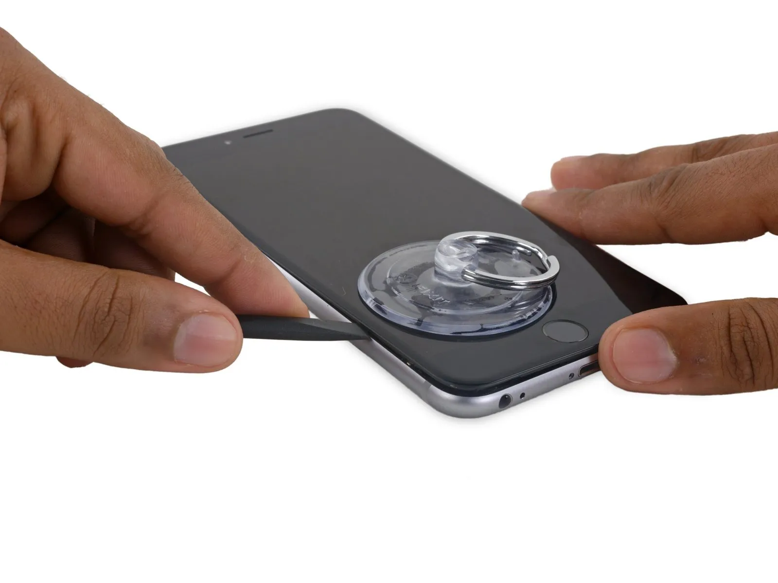
Step 5 | Opening Procedure
- In the absence of an Anti-Clamp tool, proceed with the subsequent three actions utilizing a suction handle.
- Introduce gentle warmth to the inferior border of the iPhone employing an iOpener or hair dryer, maintaining the application for approximately one minute.
- The application of heat serves to reduce the strength of the adhesive that holds the display in place, thereby simplifying the opening process.
Step 6
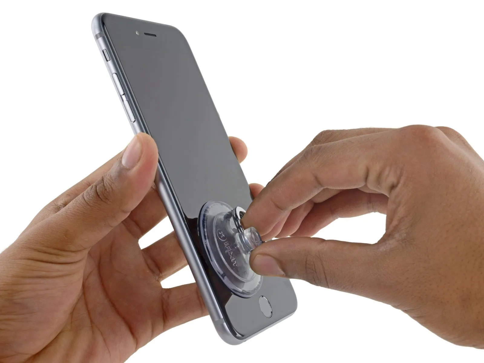
- Secure a suction cup to the lower-left portion of the display assembly.
- Should the display exhibit severe cracking, applying a transparent layer of packing tape can improve the suction cup's grip. As an alternative, a robust adhesive tape can be utilized in place of the suction cup. In situations where adhesion proves problematic, a small amount of superglue can be used to affix the suction cup to the fractured screen.
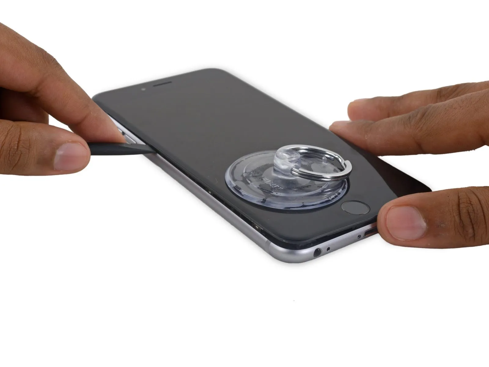
Step 7
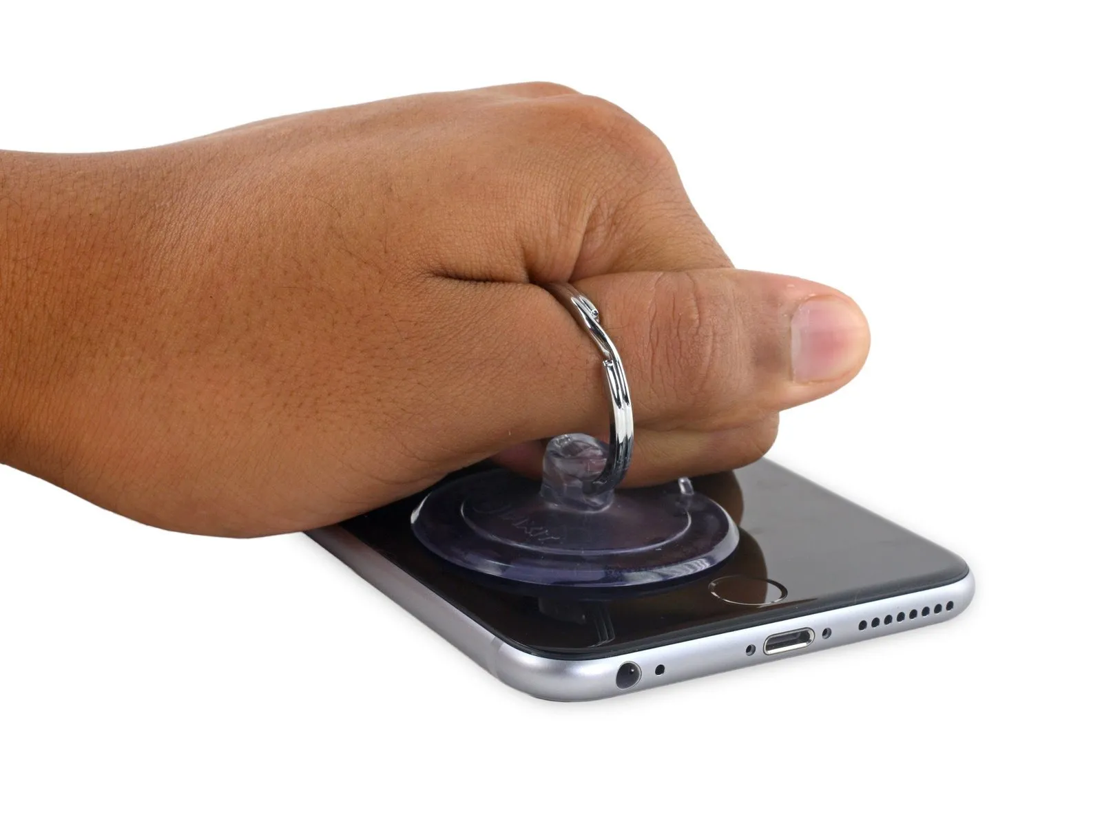
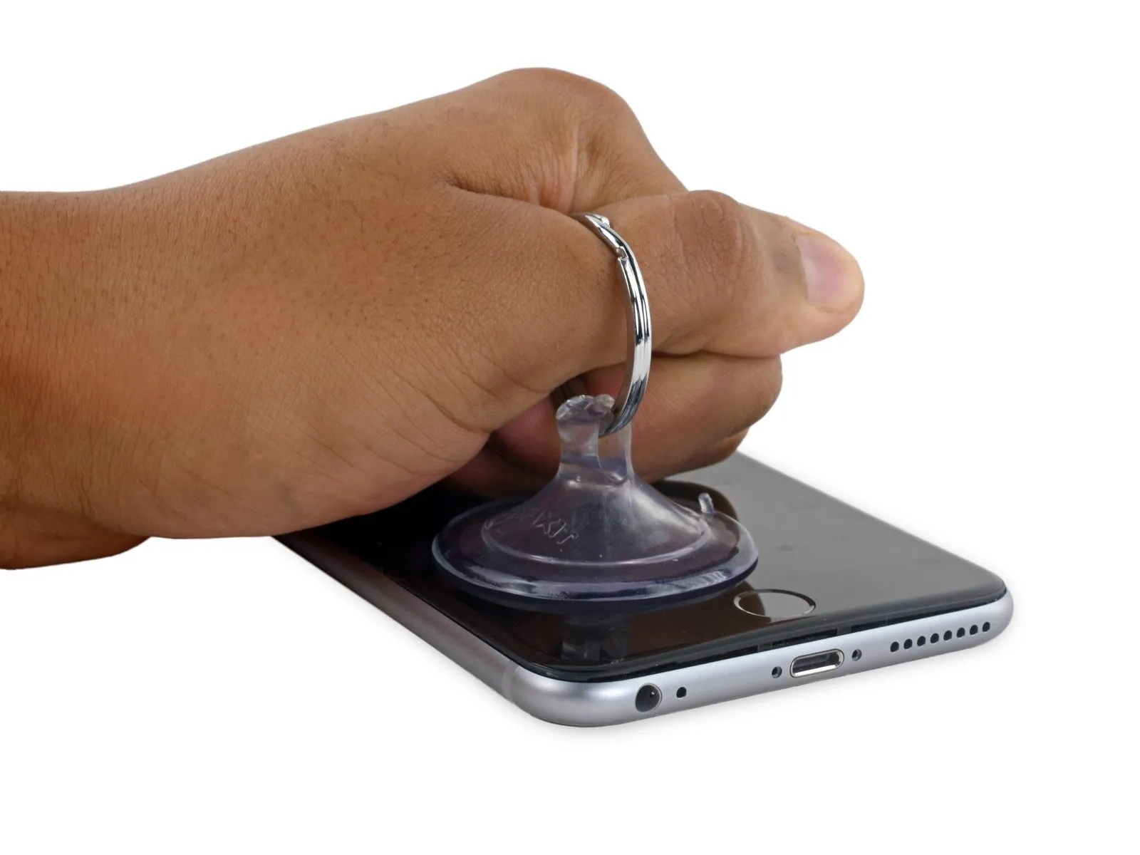
Excessive force during this action carries the risk of display assembly damage; exert only the necessary pressure to establish a small space between the display assembly and the rear case.
Step 8
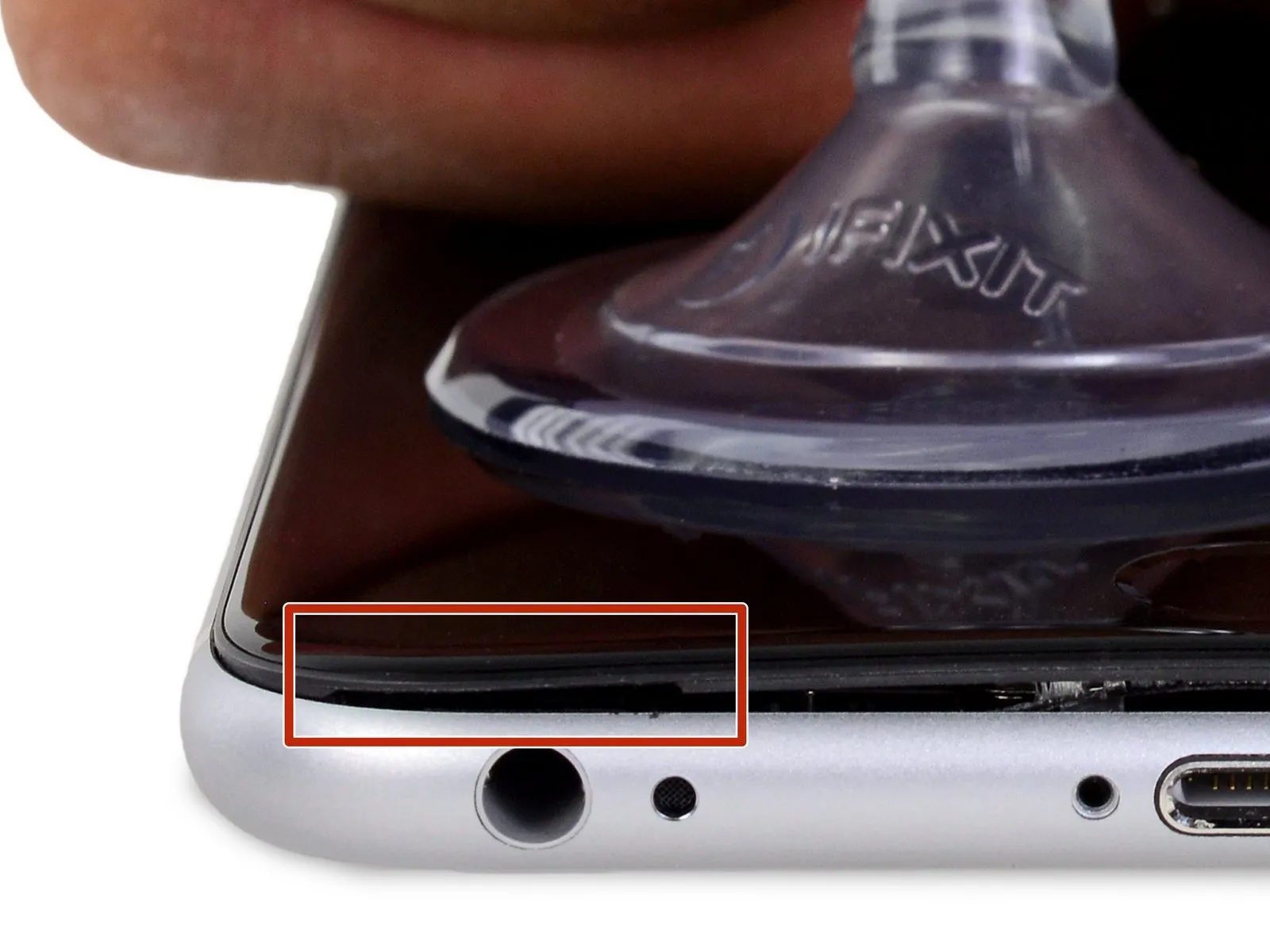

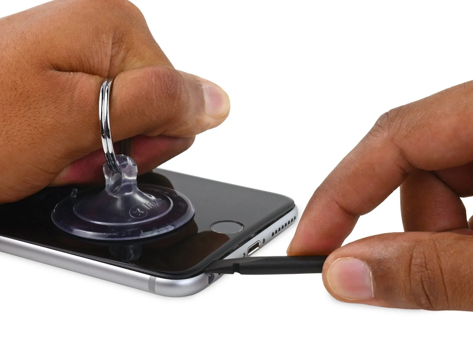
Continuing to apply consistent force with the suction cup, carefully slide the thin, wedge-shaped end of a spudger into the created space, precisely located above the headphone jack.
Step 9
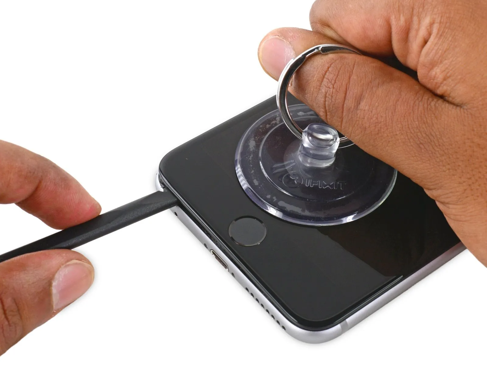
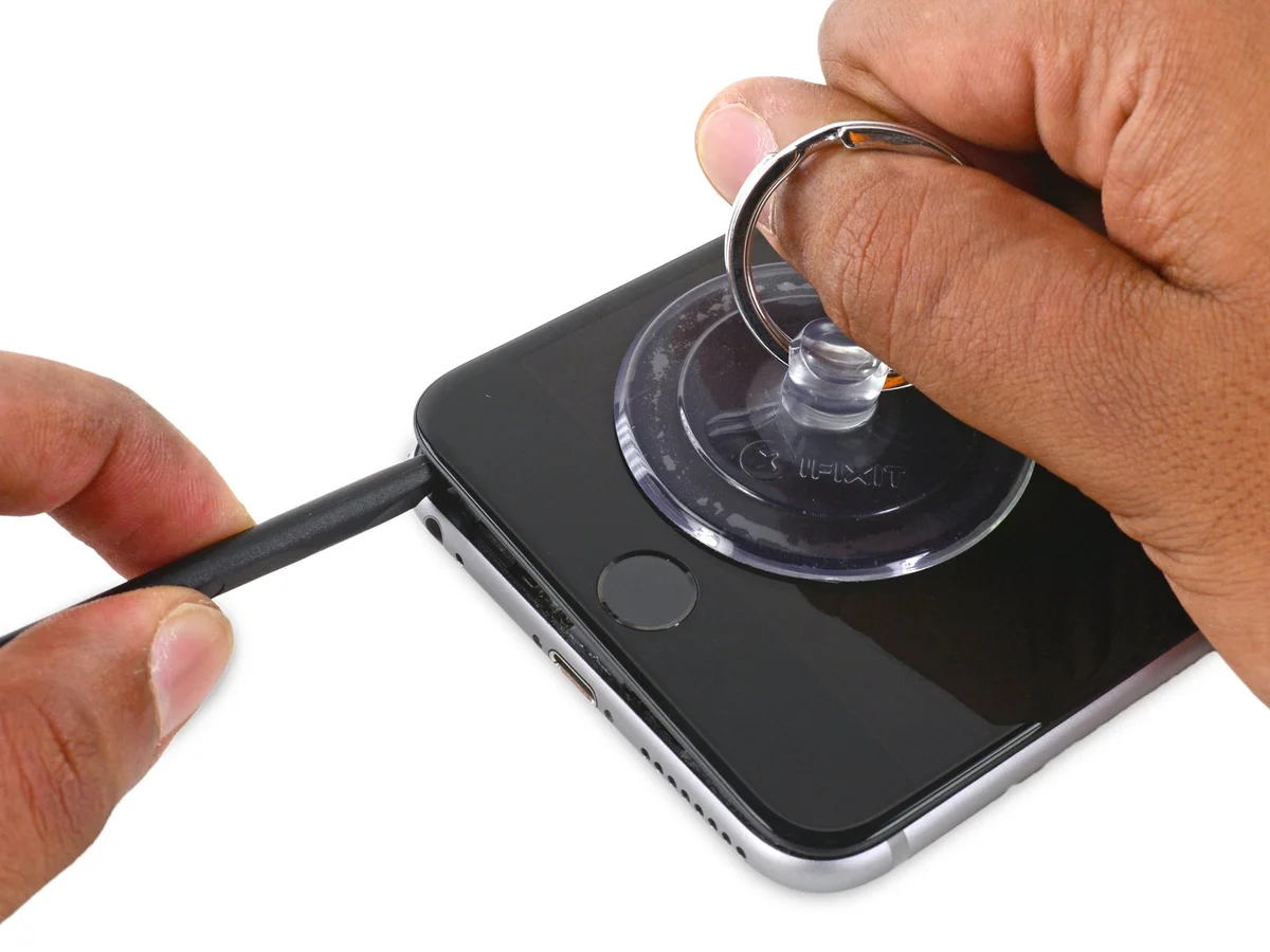
- Utilize the spudger, rotating it to increase the separation distance observed between the front panel assembly and the rear enclosure.
Step 10


Step 11
Step 12


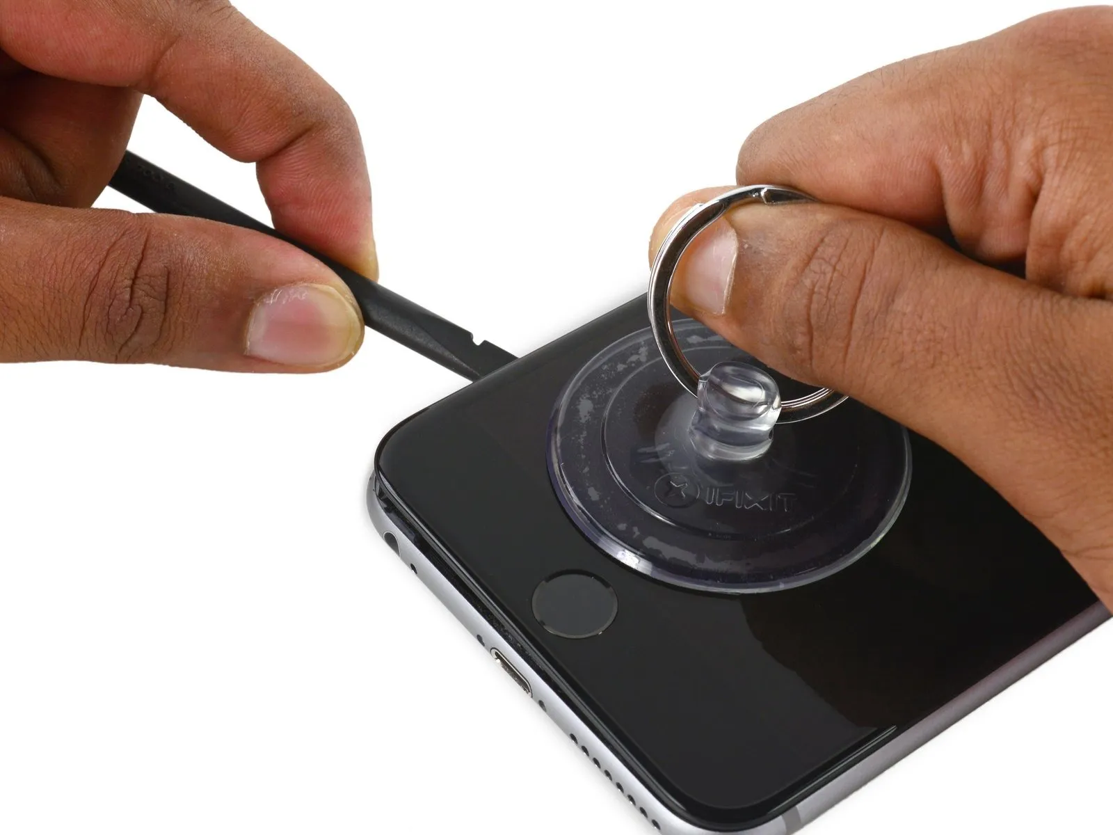
- Utilize the flat end of the spudger to gain access beneath the right perimeter of the display assembly.
- Advance the spudger along the right vertical plane.
Step 13


- Employ a plastic opening tool to maintain pressure on the rear enclosure as you lift the suction cup, facilitating the phone's opening.A plastic opening tool is essential for this step.Avoid detaching the display assembly entirely, as doing so risks harming the delicate data cables situated along the upper portion of the iPhone.
- Care must be taken to prevent damage to the data cables during the opening process.
Step 14

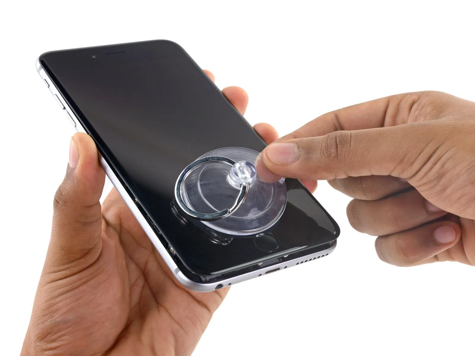
- To detach the suction cup from the display surface, grasp and lift the small protrusion located on its body.
Step 15

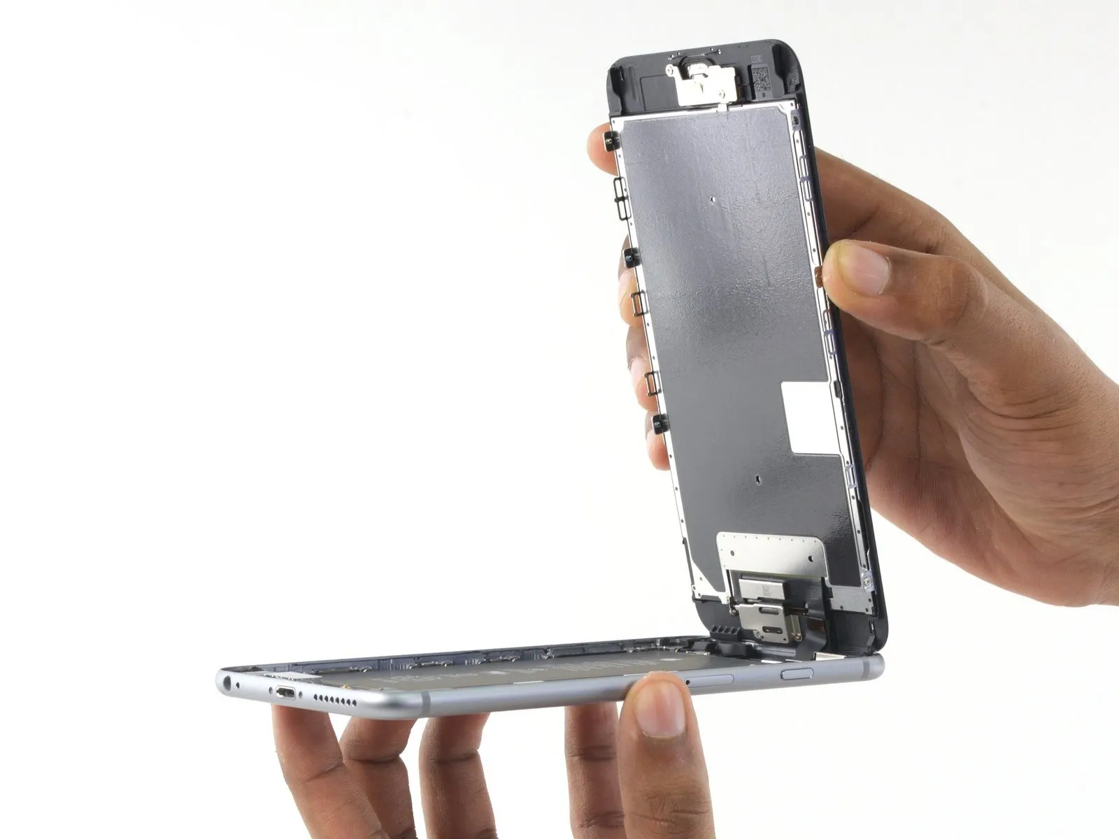

- Carefully hold thedisplay assemblyto initiate the opening process of the device, leveraging the upper front panel clips as a pivot point.
- Position the display to approximately a 90-degree angle, and secure it in a propped position to facilitate your repair work.
- Avoid exceeding a 90-degree opening angle, as the display remains tethered to the phone's upper section via thedisplay, digitizer, and front camera cableswhich are susceptible to damage if stressed.
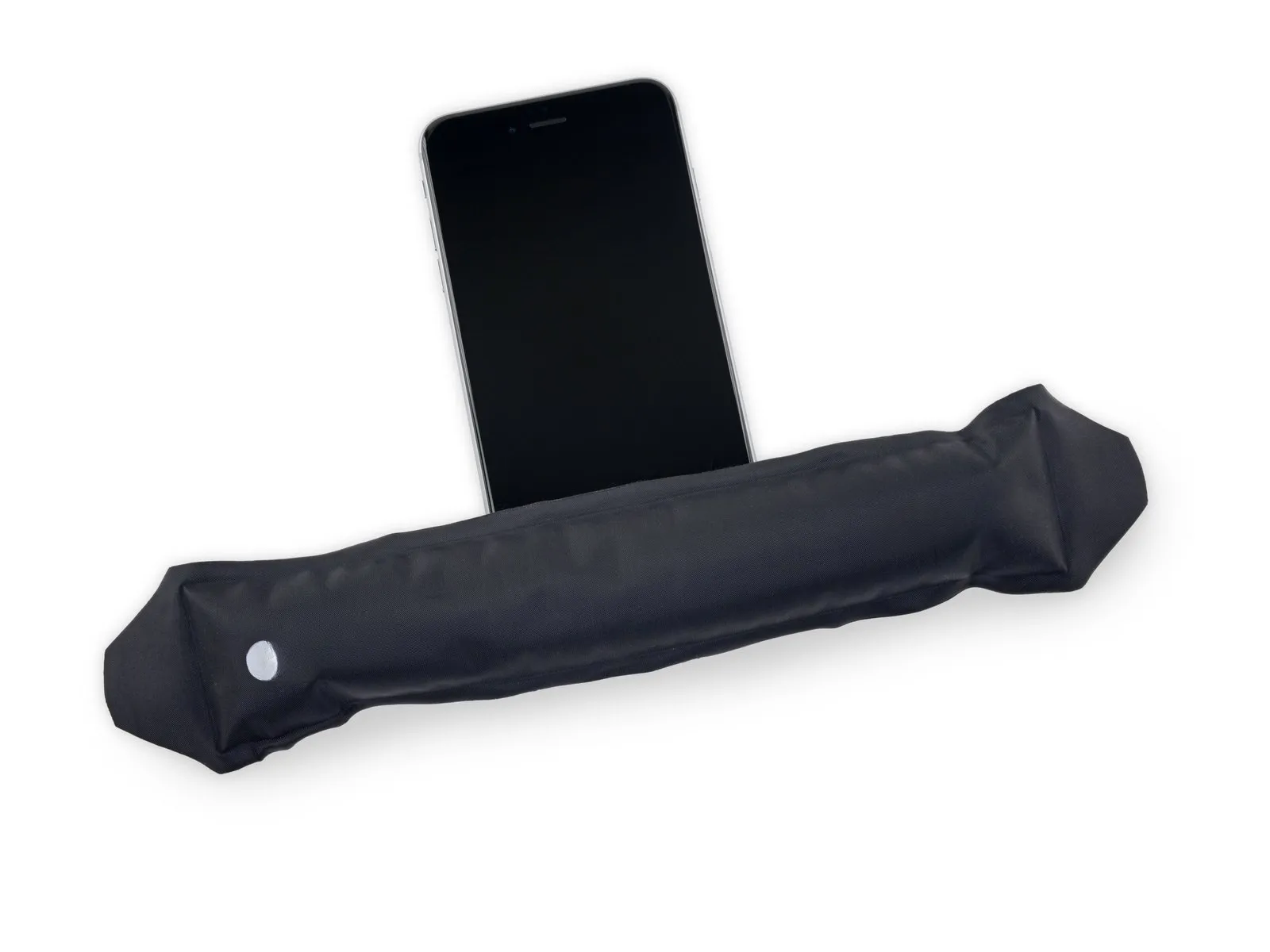
- Employing a rubber band to maintain the display's stability during the repair process minimizes stress on the delicate display cables.
- As an alternative, an unopened can of beverage can be utilized to provide support for the display.
Step 16 | Battery Connector
- Detach the battery connector bracket from the logic board by eliminating two fasteners.The fasteners in question are Phillips head screws.These screws hold the bracket in place.
- A single screw, measuring 2.9 millimeters in length, is required for this process.Additionally, a 2.3-millimeter screw is also necessary.
- Both screws must be removed to proceed.Ensure careful handling of these small screws.
Step 17
Step 18

Step 19


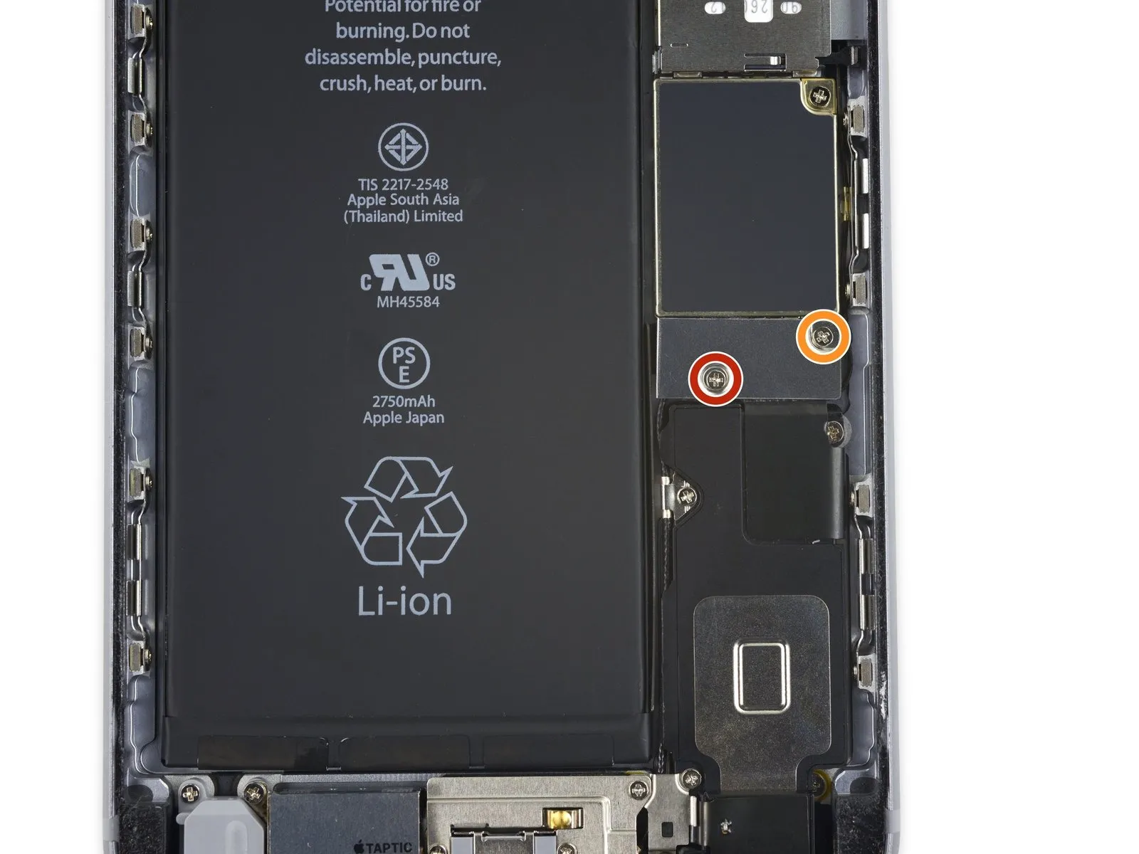
Step 20 | Display Assembly
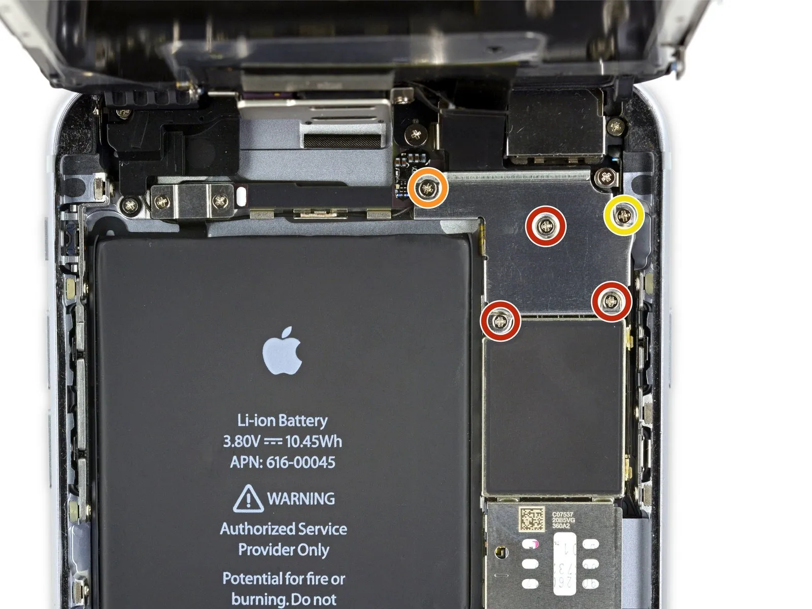
- Three screws, each measuring 1.3 millimeters in diameter, must be extracted.
- A single screw with a 1.6-millimeter diameter is also required for removal.
- Additionally, one screw with a 3.0-millimeter diameter needs to be taken out.
Ensuring correct placement during reassembly is vital; specifically, the 3.0-millimeter screw must be positioned in the upper-right section of the bracket to prevent potential damage to the logic board.
Step 21

Step 22

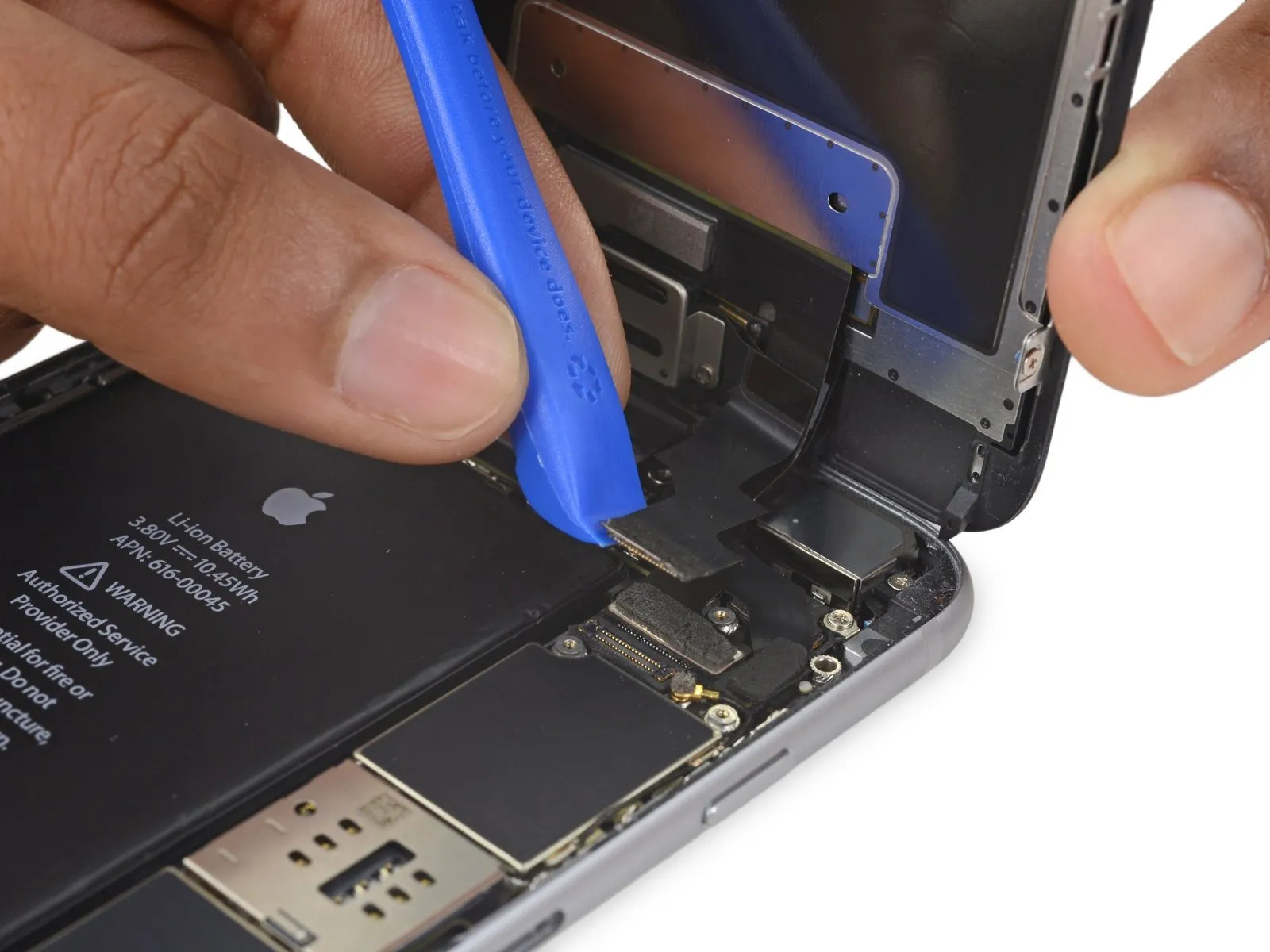
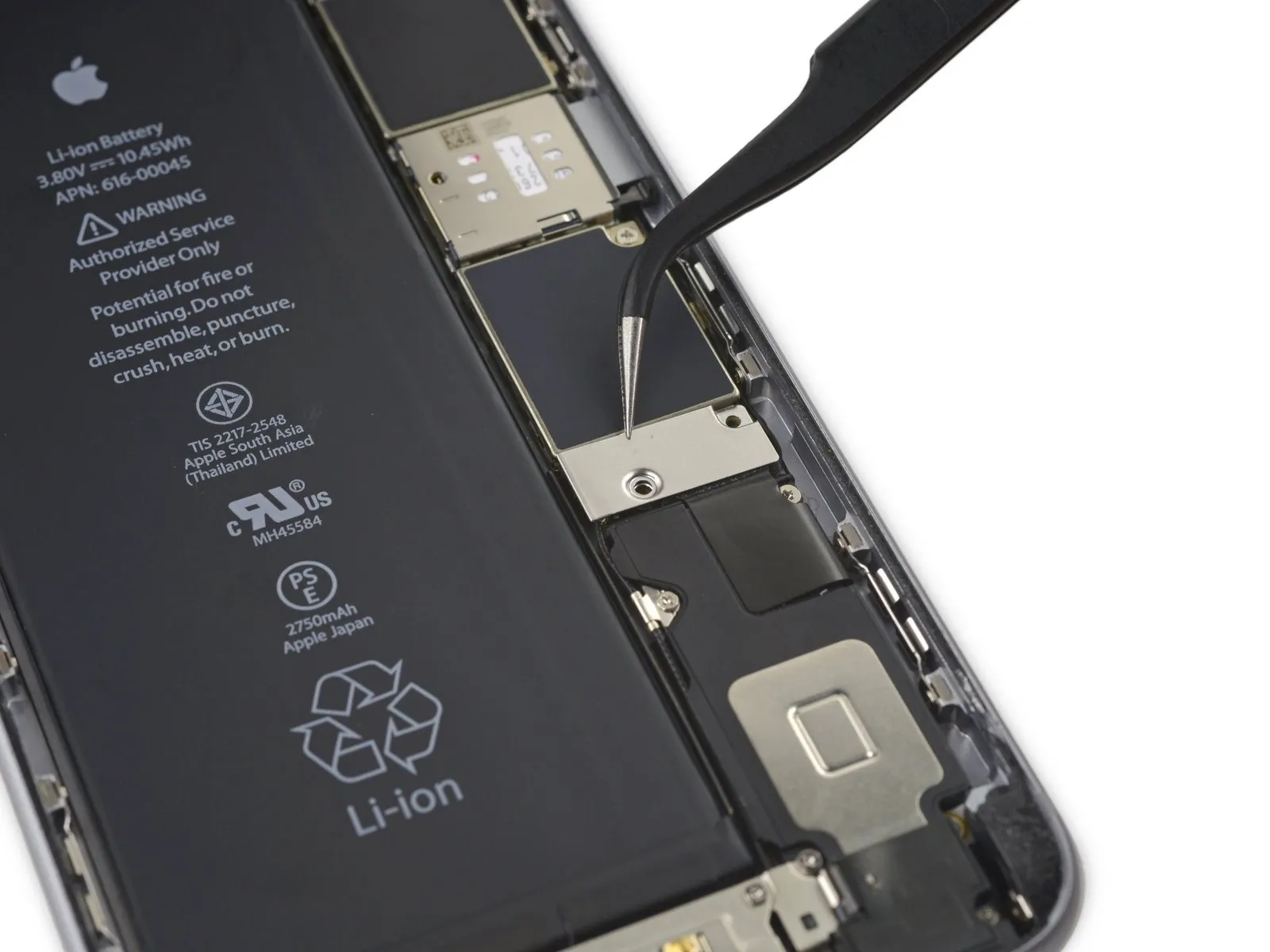
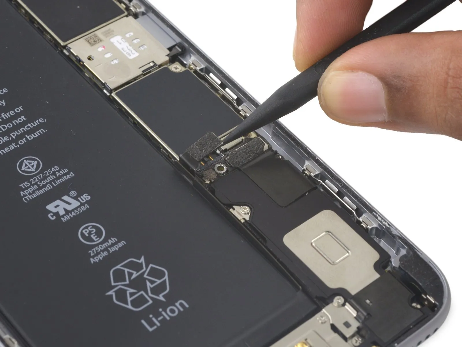
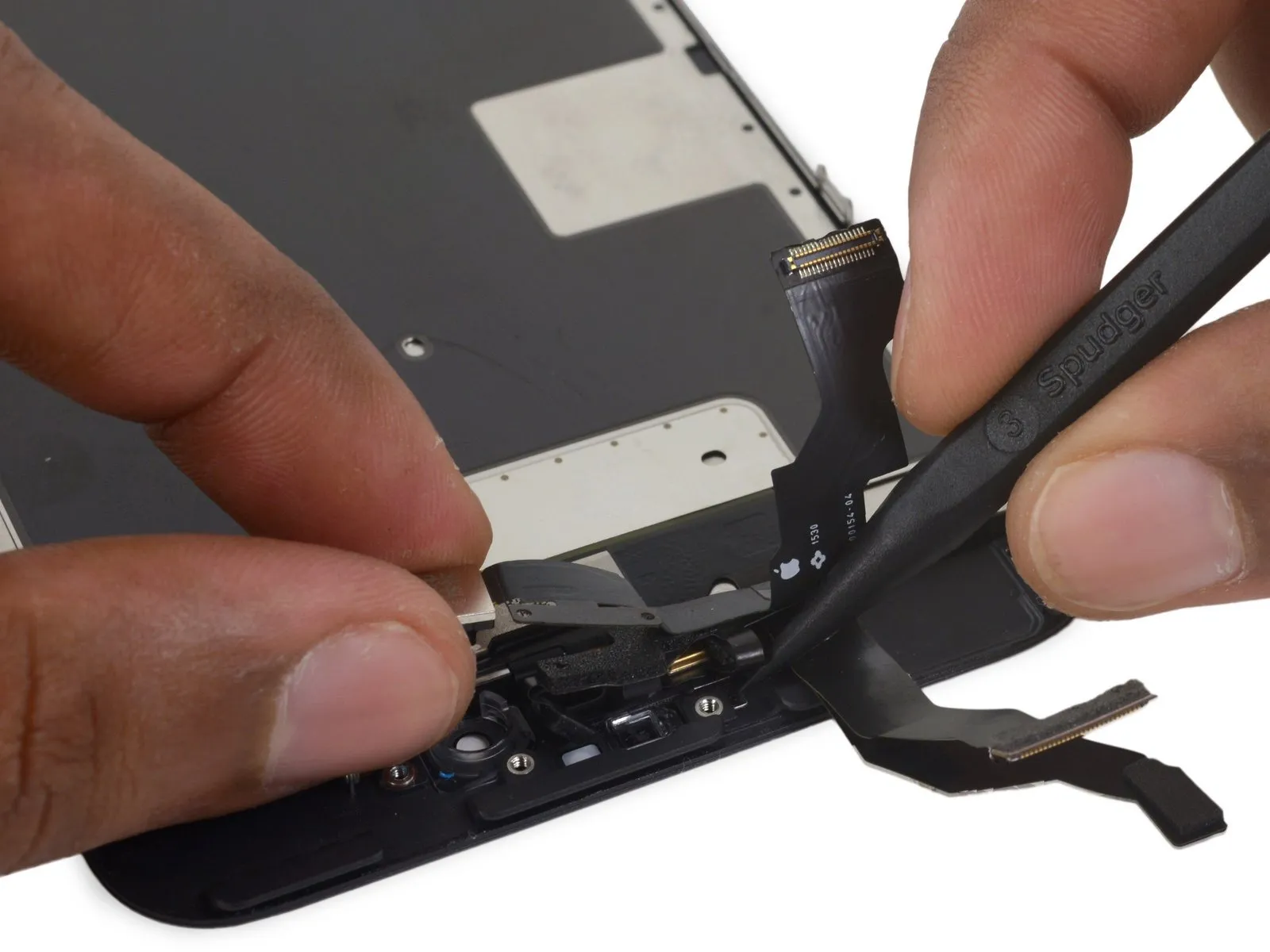
- Exercise caution, ensuring that prying force is applied solely to the connector body, avoiding damage to the socket situated on the logic board.
- Employ a plastic tool designed for opening electronics to carefully release the front-facing camera and sensor cable connector.
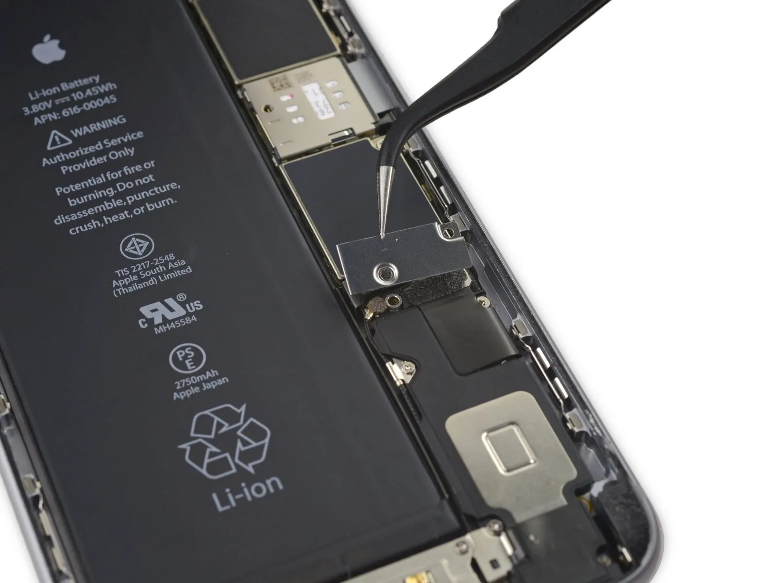
Step 23
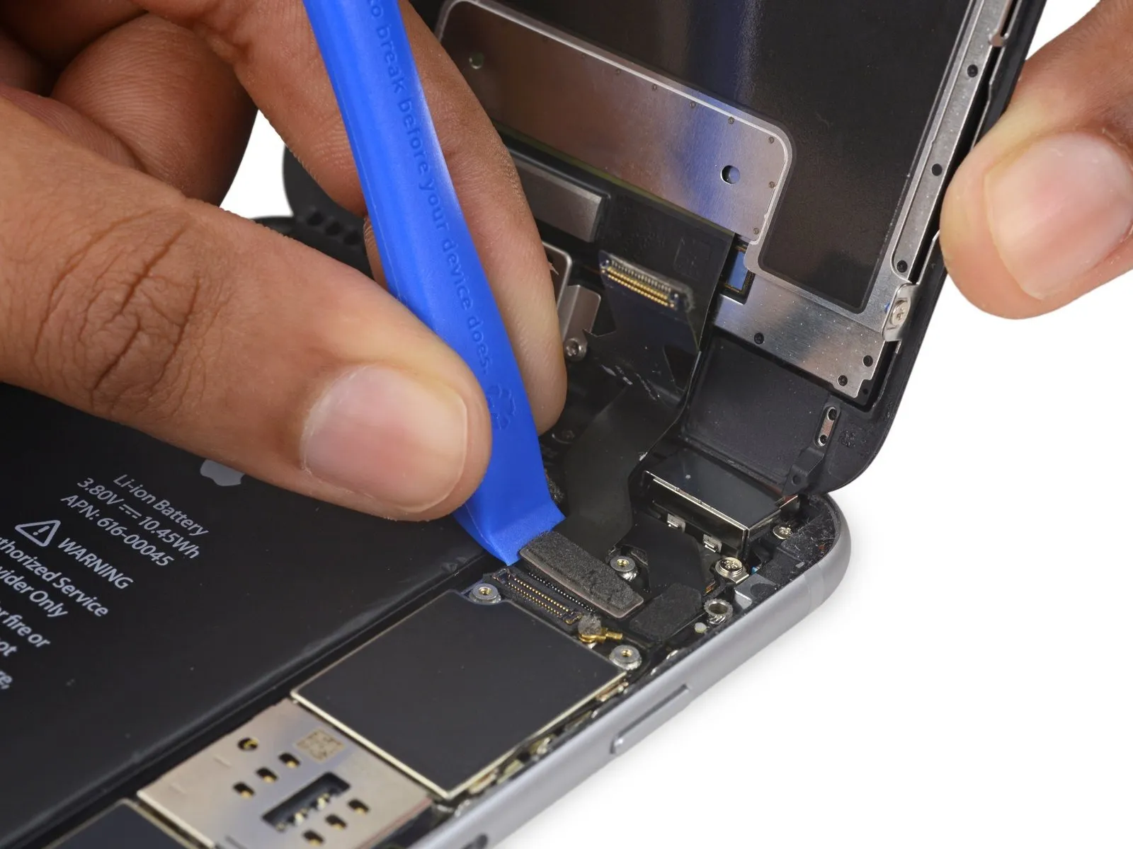

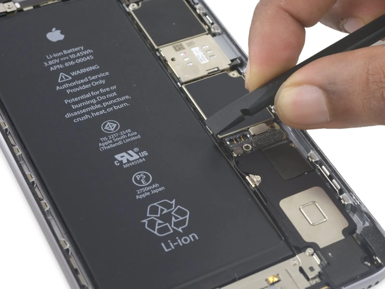
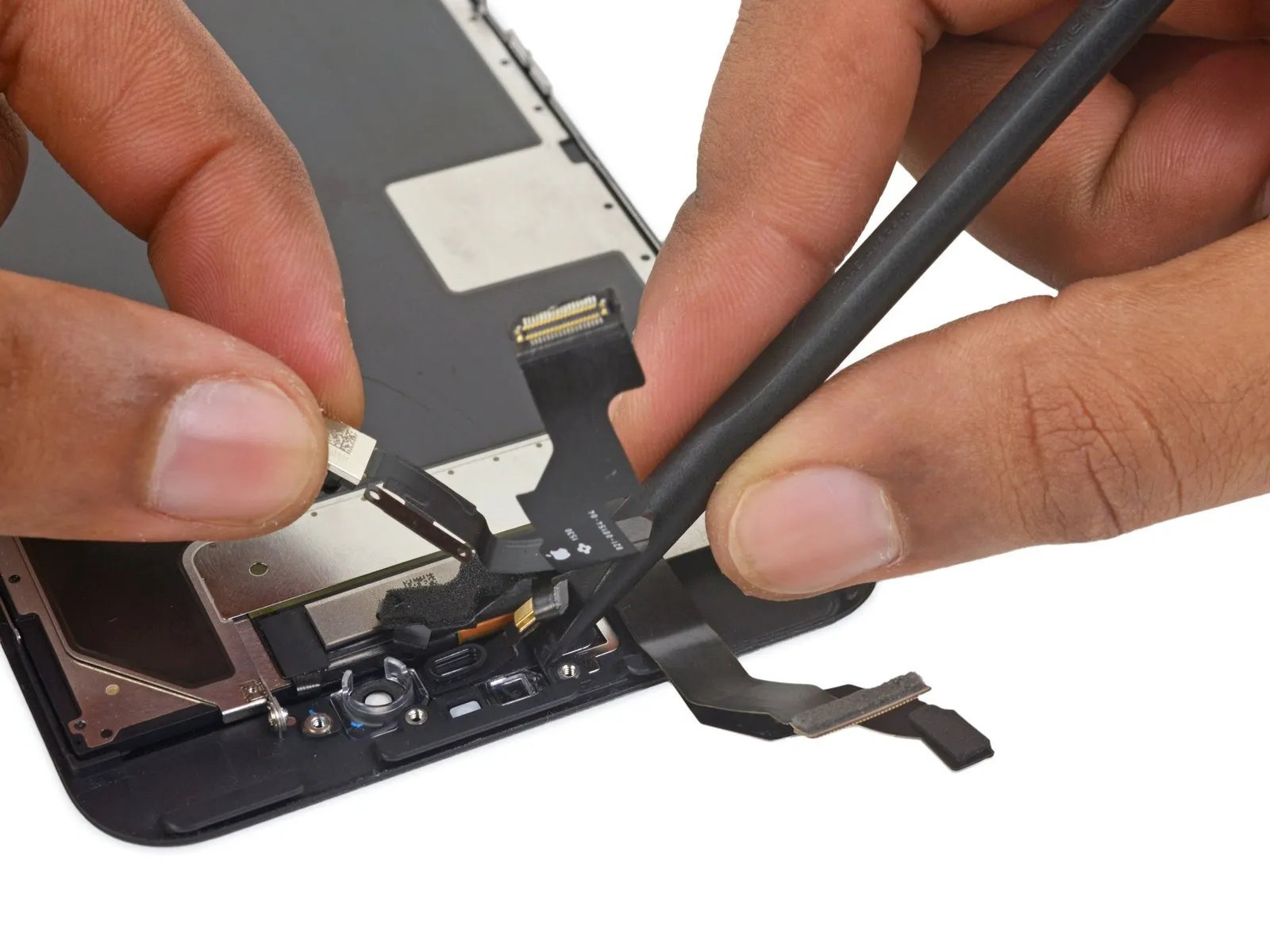
- Employ a specialized plastic pry tool to release the digitizer cable, lifting it vertically away from its connection point on the logic board.
- During the reconnection of the digitizer cable, avoid applying pressure to the central area of the connector; instead, apply force to one end, then the opposing end, as this central pressure can deform the component and lead todigitizer damage.
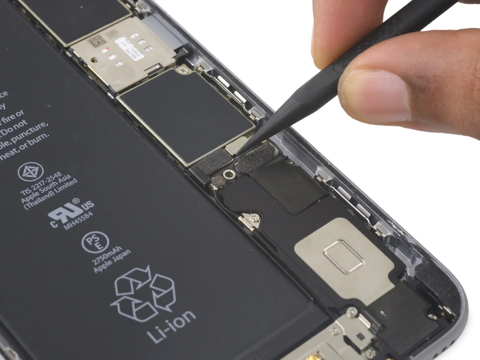
Step 24
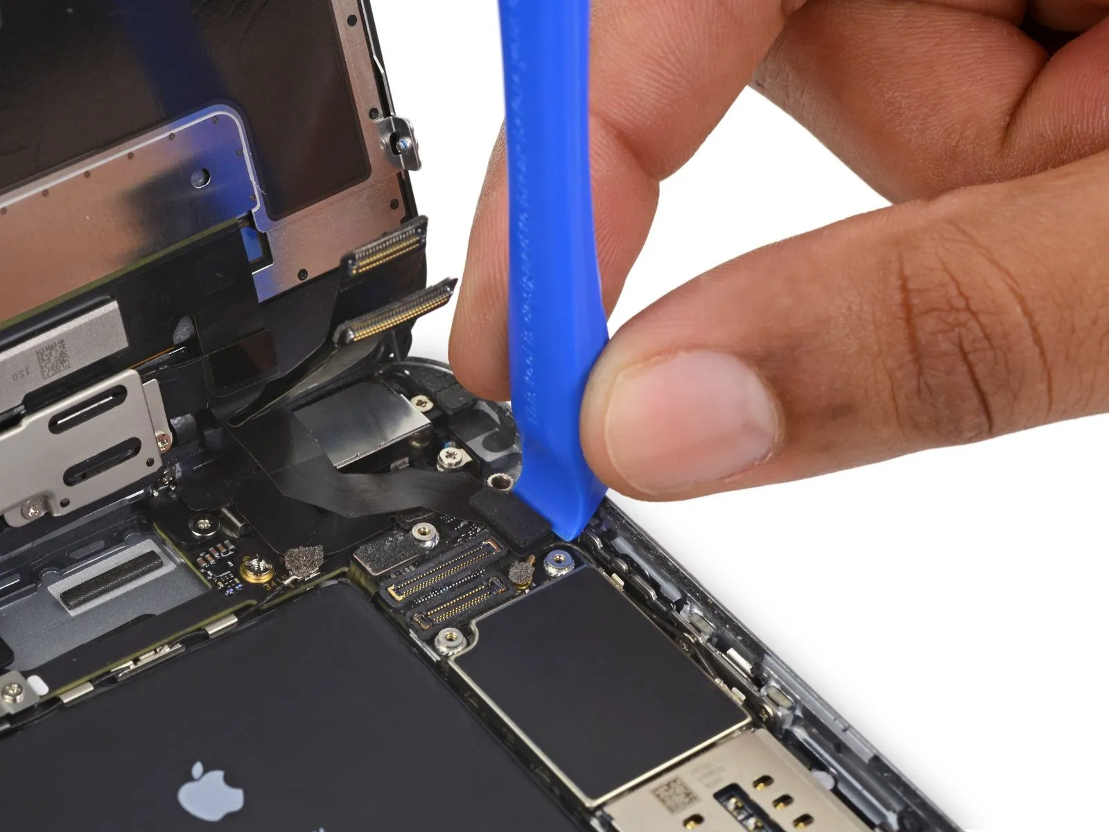

- Prior to detaching or reattaching the cable within this procedure, confirm the battery's power is completely removed.
- To release the home button/fingerprint sensor cable, carefully lift it vertically away from its connection point on the logic board.
Step 25
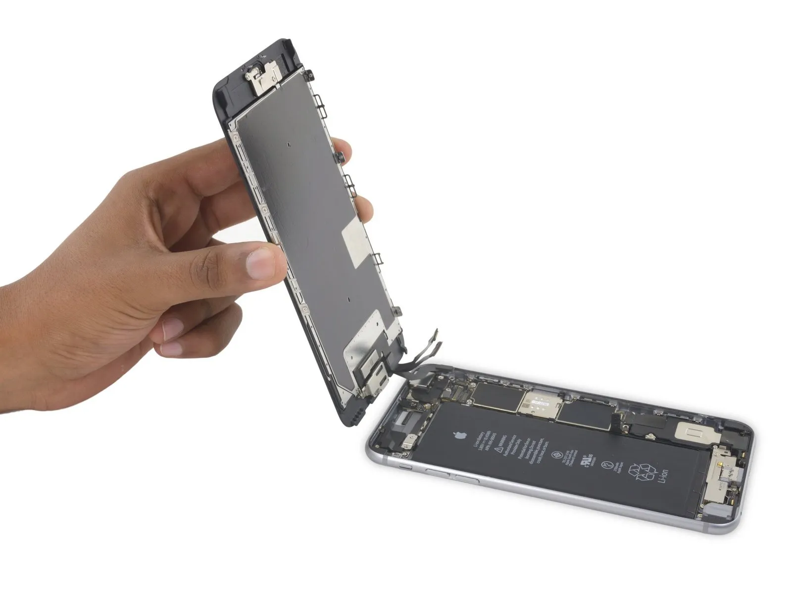
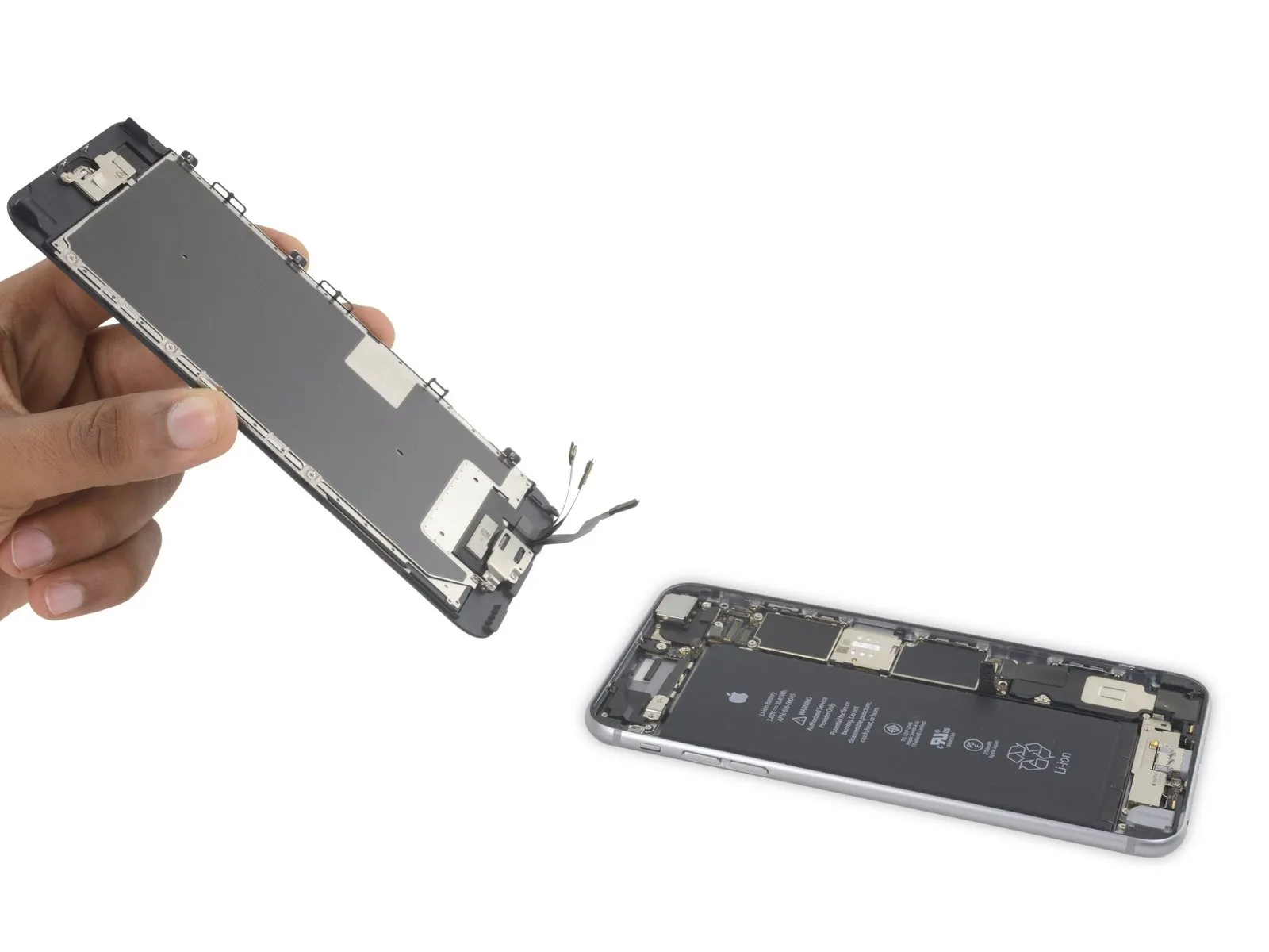
- Detach the display unit from the device.
- When putting the device back together, halt at this stage should you desire to substitute the adhesive securing the display's perimeter.
Step 26 | Home Button Assembly

Step 27
Step 28

Step 29
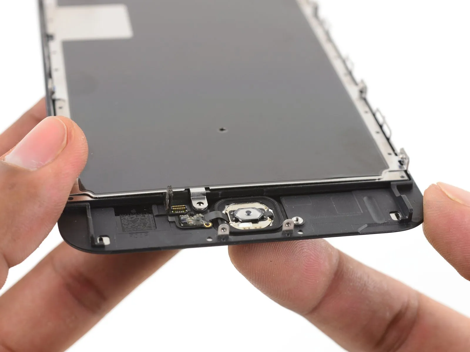
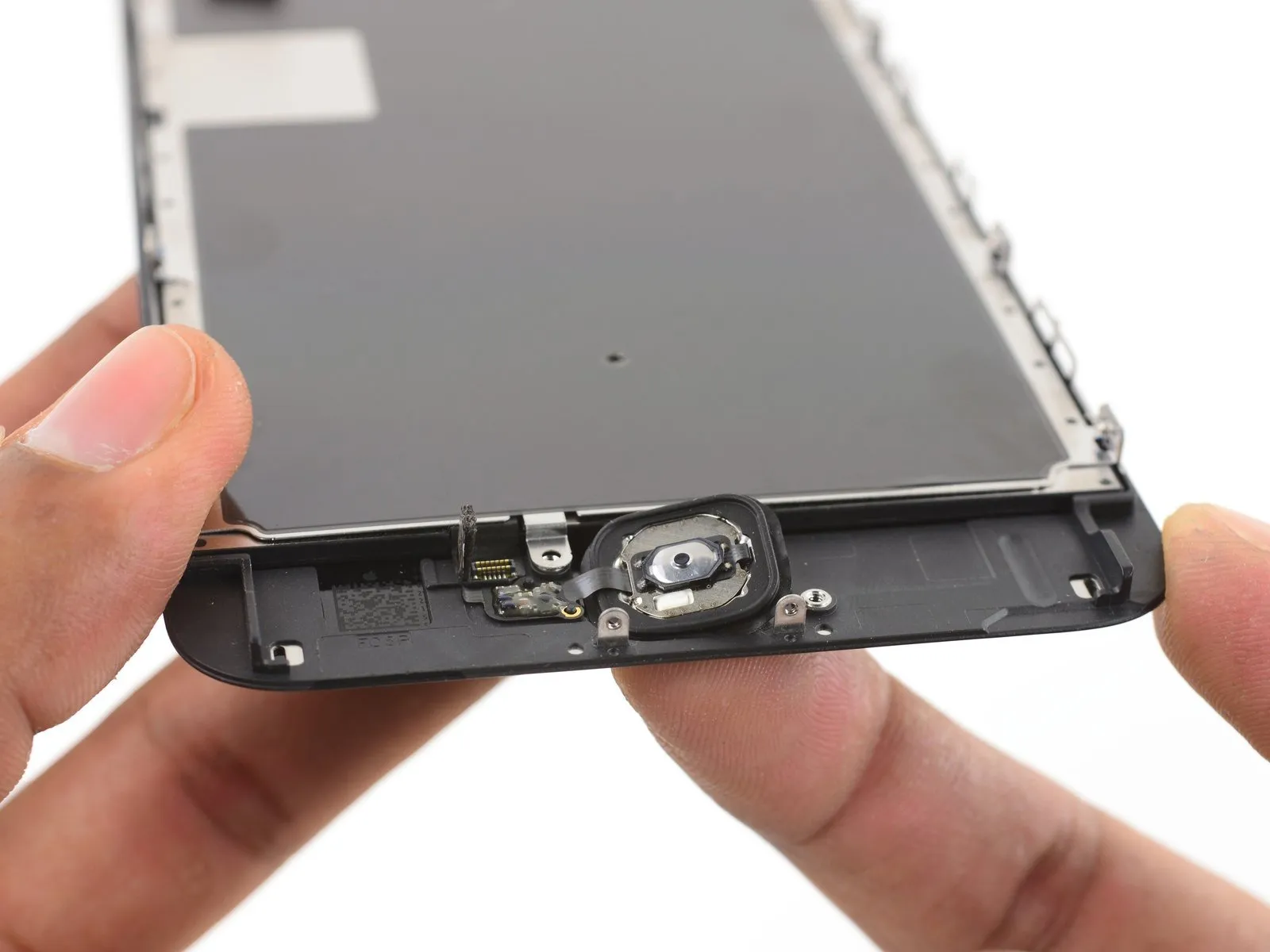
- Therubber gasketThis component, positioned around the home button, possesses a delicate construction and is prone to tearing.
- To facilitate separation, introduce moderate warmth (utilizing an iOpener, heat gun, or hair dryer) which will reduce the adhesive's strength holding the home button gasket in place.
- With your index finger, exert a controlled upward force on the home button's surface, applying consistent and substantial pressure to gradually disengage the rubber gasket from the front panel.
Step 30
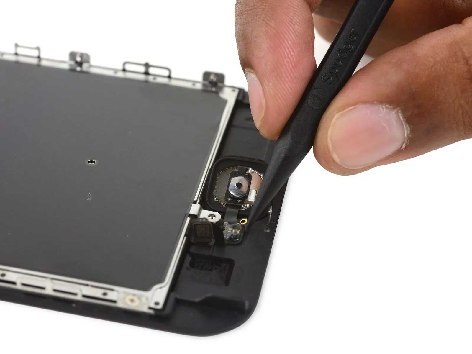
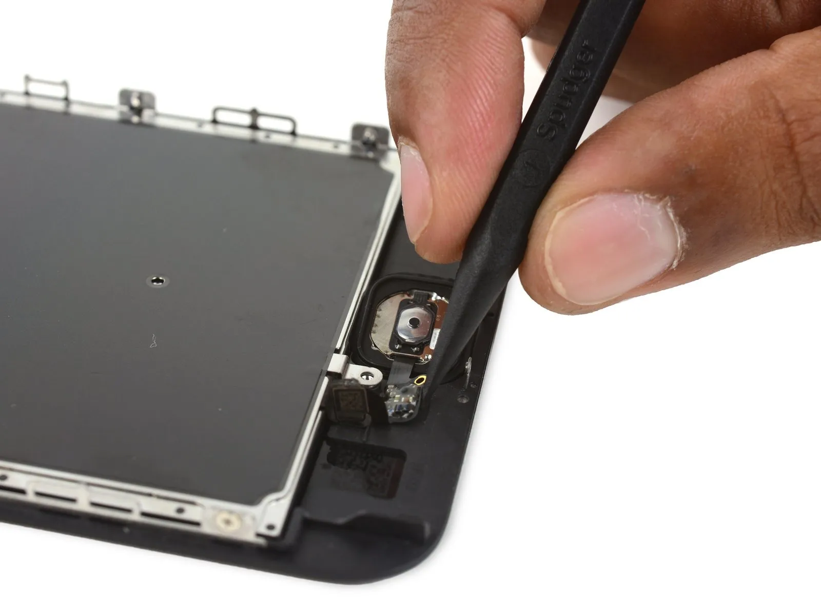
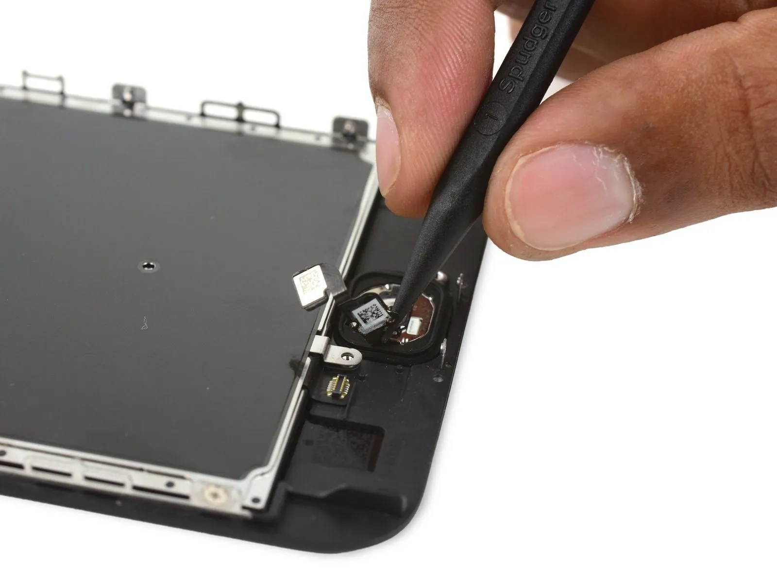
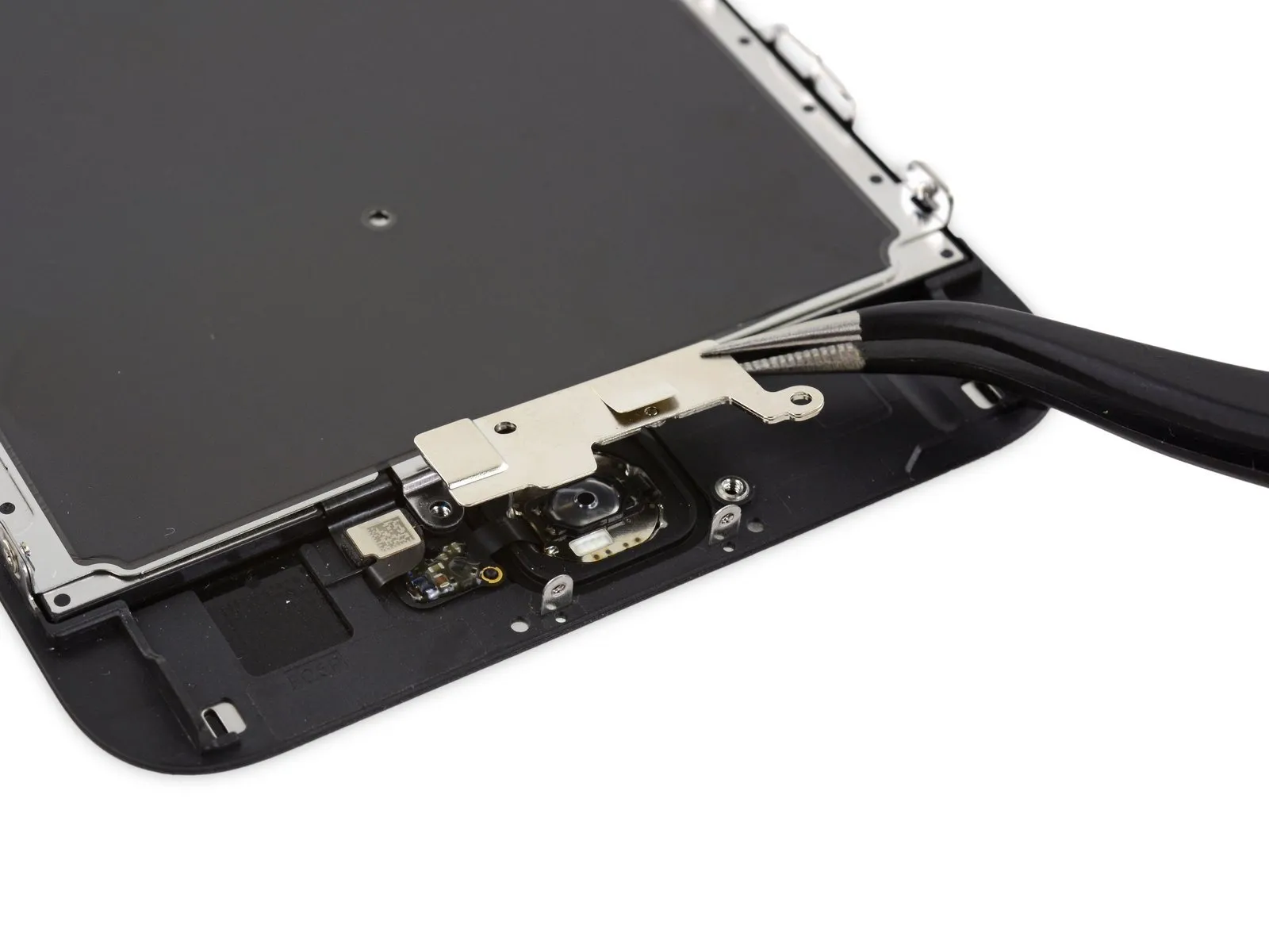
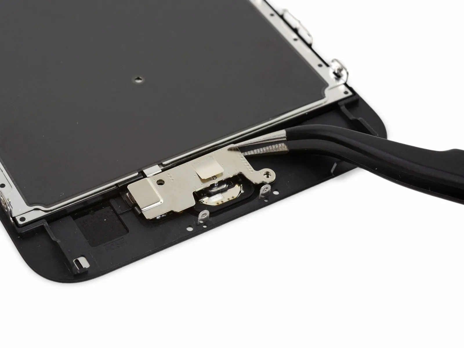
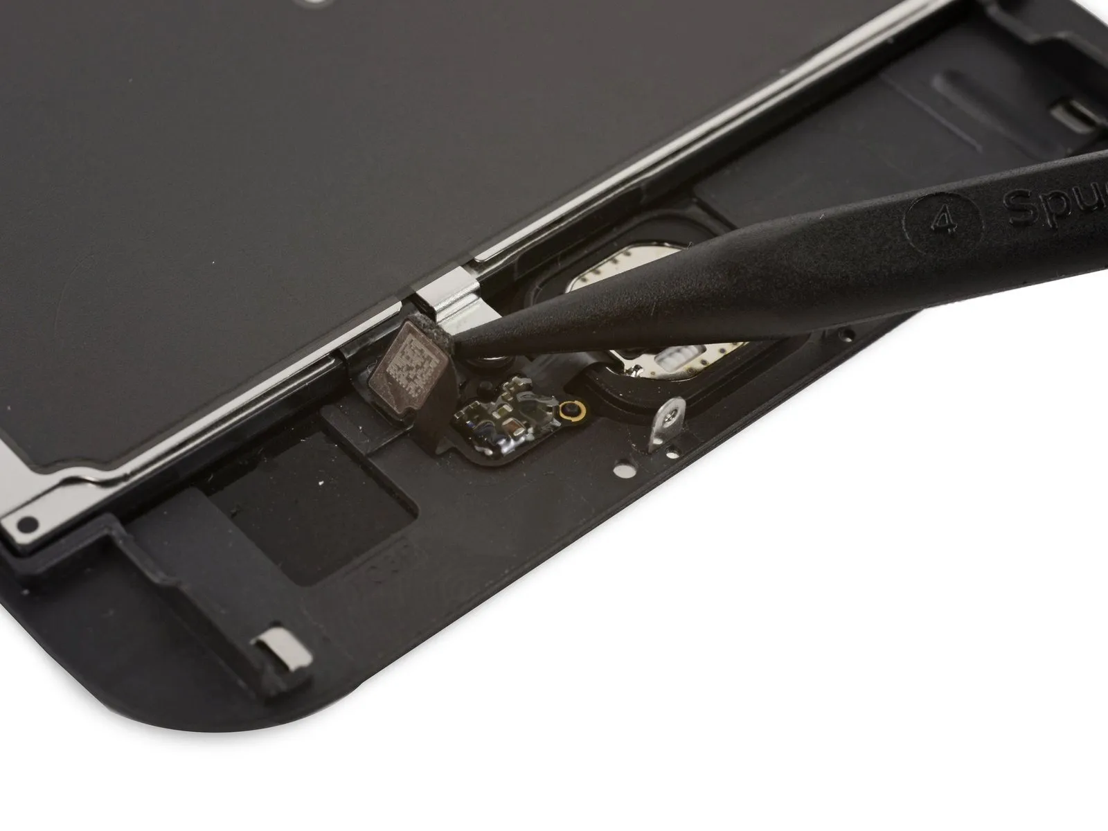
- Employ the tapered tip of a spudgerto carefully separate the home button flex cable, which is only weakly attached, from the display assembly.
Step 31

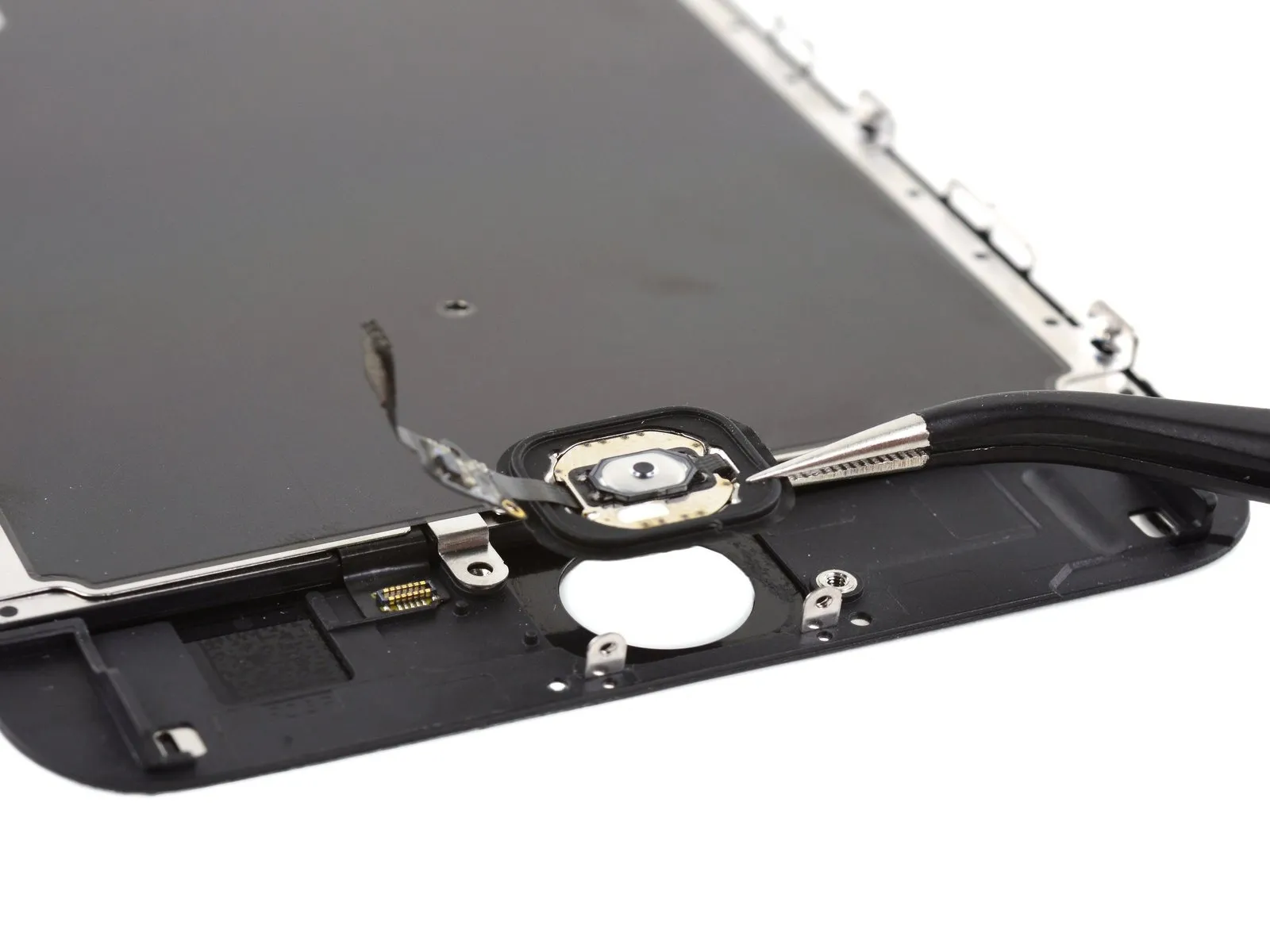
- Carefully detach the home button assembly from the device.
Step 32 | Earpiece Speaker

- To begin the repair, detach the subsequent three fasteners.These fasteners are Phillips head screws.:
- You will require the removal of two fasteners, each measuring 2.7 millimeters in length.Additionally, a single fastener with a 1.4-millimeter dimension must be taken out.
- This single fastener is also a screw.The screws are all Phillips head.
Step 33
Step 34
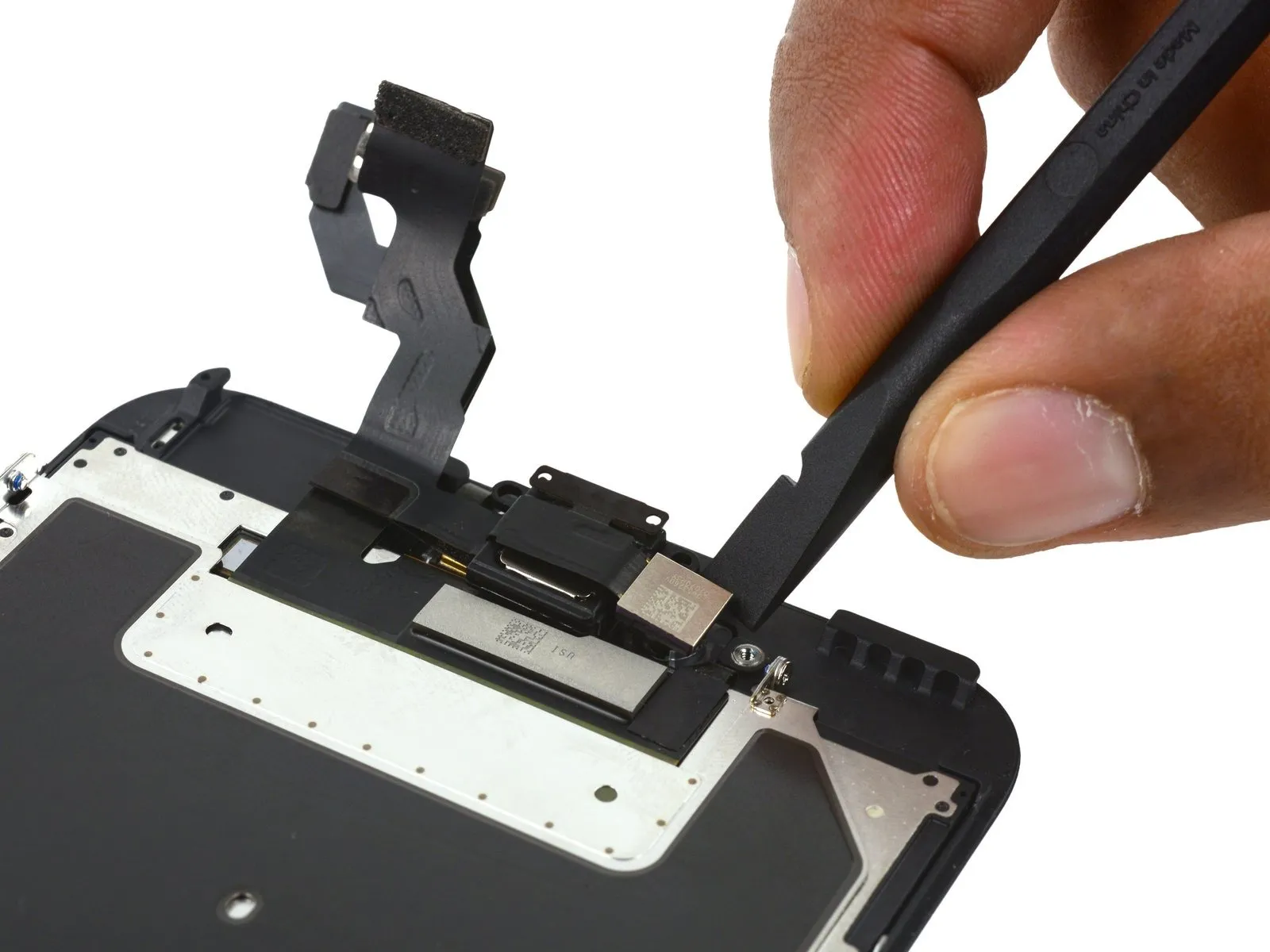
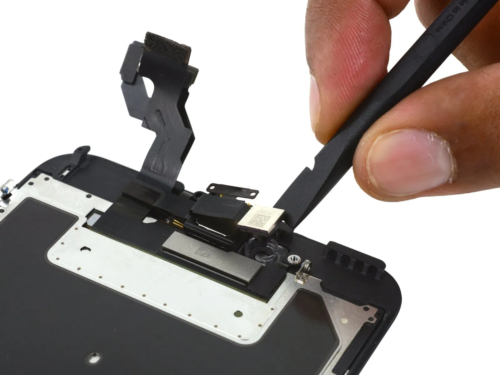
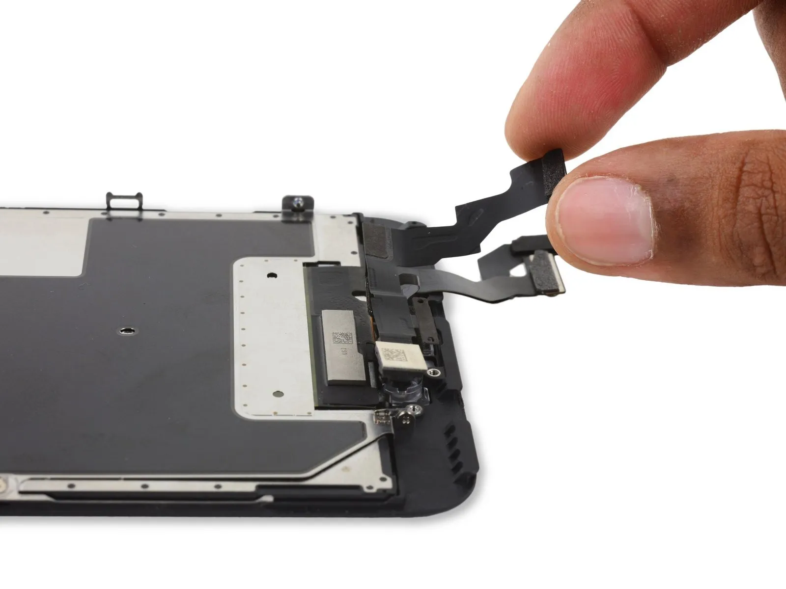
- Employ the planar edge of a spudgerto disengage the FaceTime camera assembly from its surrounding structure.
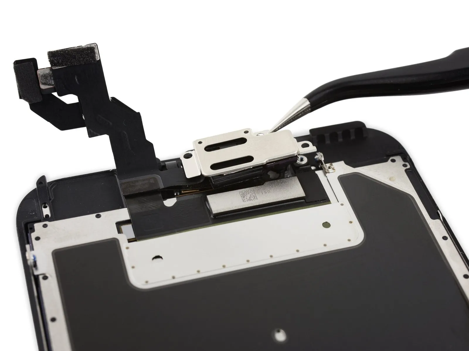
Step 35
- Carefully retract the FaceTime camera assembly and detach the earpiece speaker component.
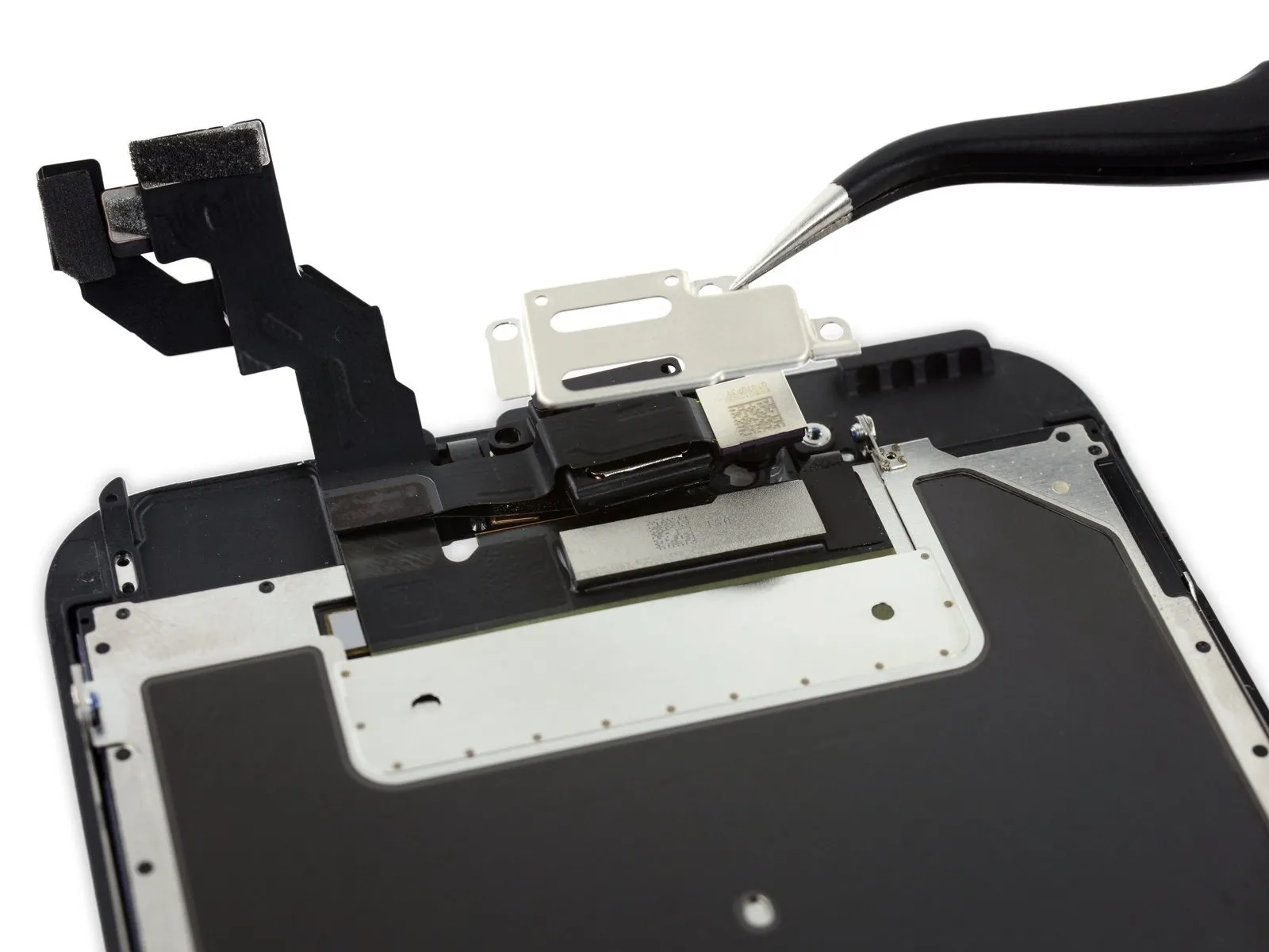
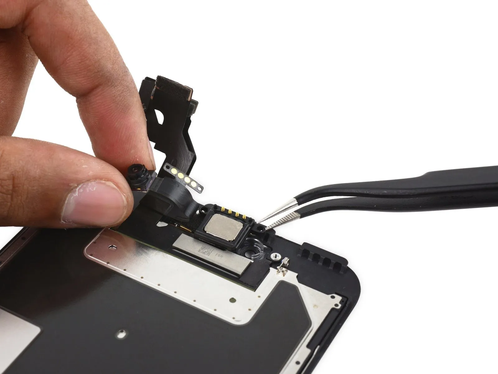
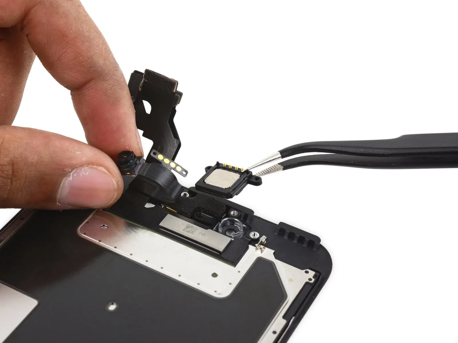
Step 36 | FaceTime Camera and Sensor Assembly


- Employ the tapered end of a spudgerto carefully disengage the ambient light sensor from its secure placement within the front panel's structure.
Step 37

- Carefully position the tapered end of a spudger into the gap formed by the microphone flex cable and the front panel, utilizing it to separate the adhesive securing the cable.
Step 38


- Employ the broad, planar end of a spudger to gently separate the microphone and earpiece gasket from its adhesive bond.spudgerto lift up the microphone and earpiece gasket.
Step 39
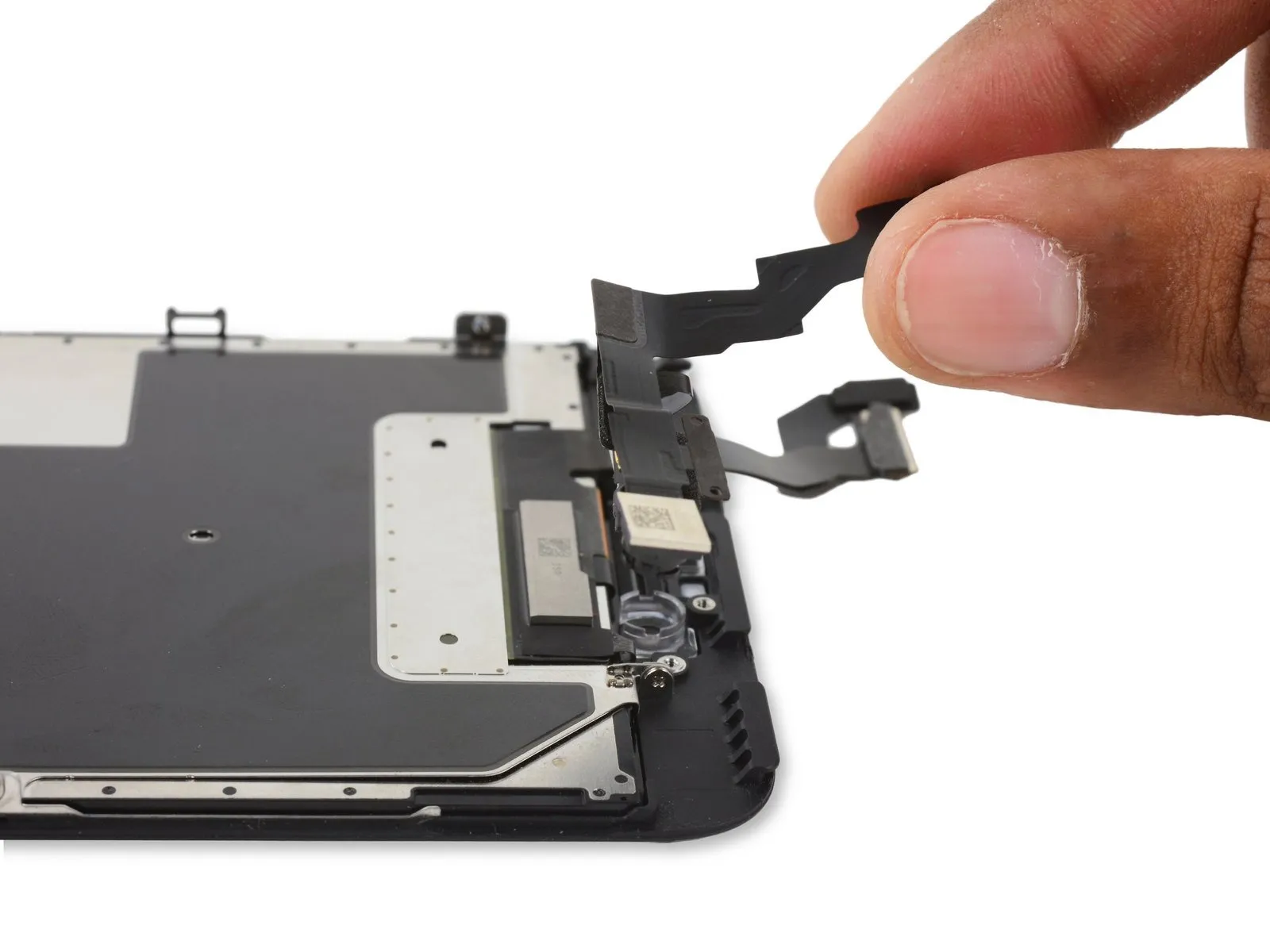
- Carefully detach the FaceTime camera and its associated sensor component.
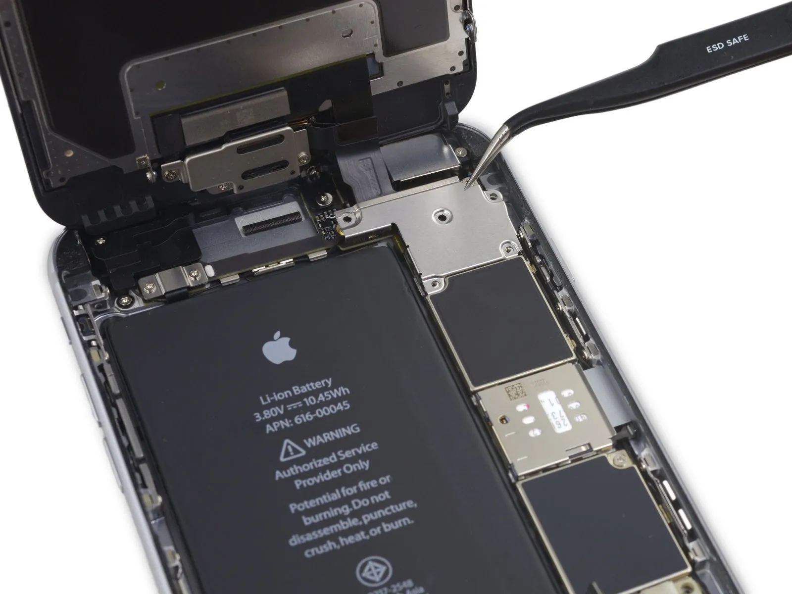
Step 40 | Display EMI Shield
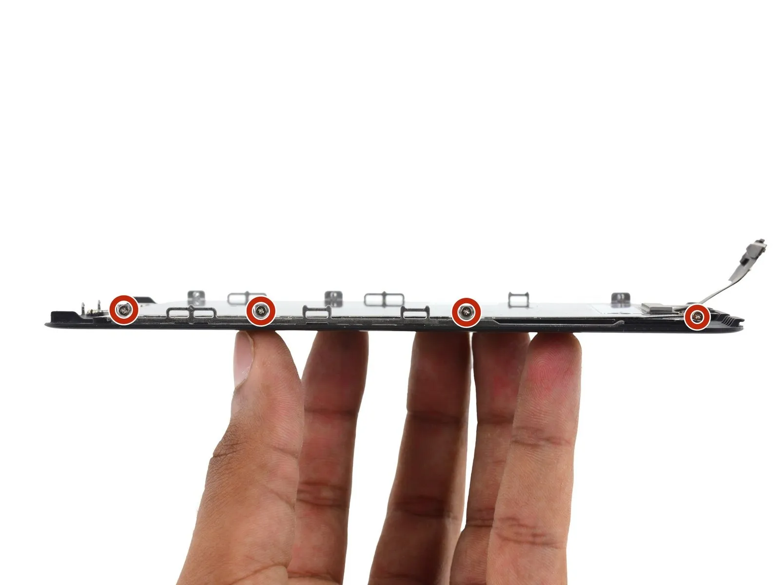

- Detach the seven 1.5 mm Phillips screws securing the electromagnetic interference (EMI) shield covering the display.
Observe that the screw located furthest to the right in the initial image is set back approximately1.8 cm from the display's perimeter.
Step 41
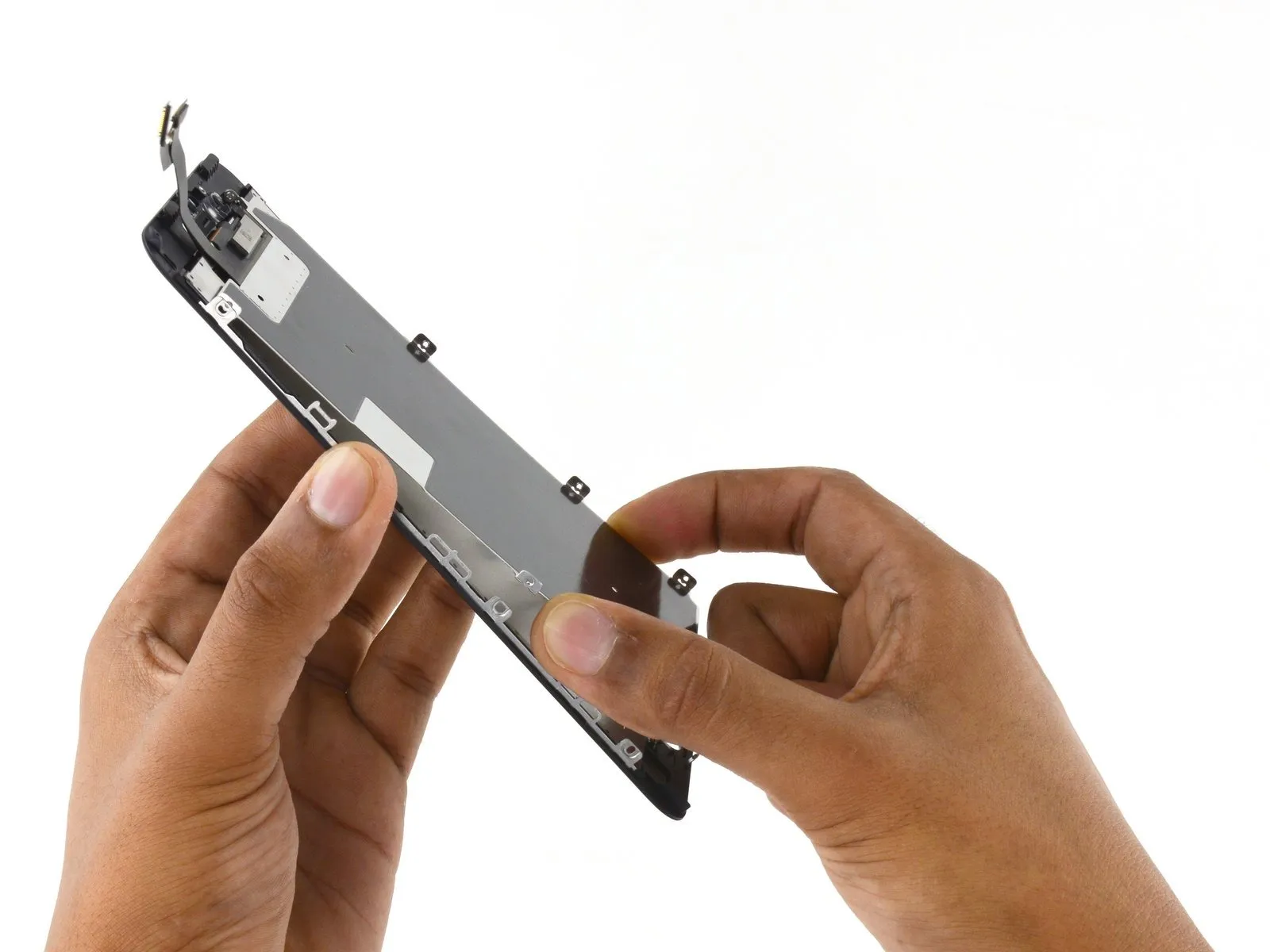
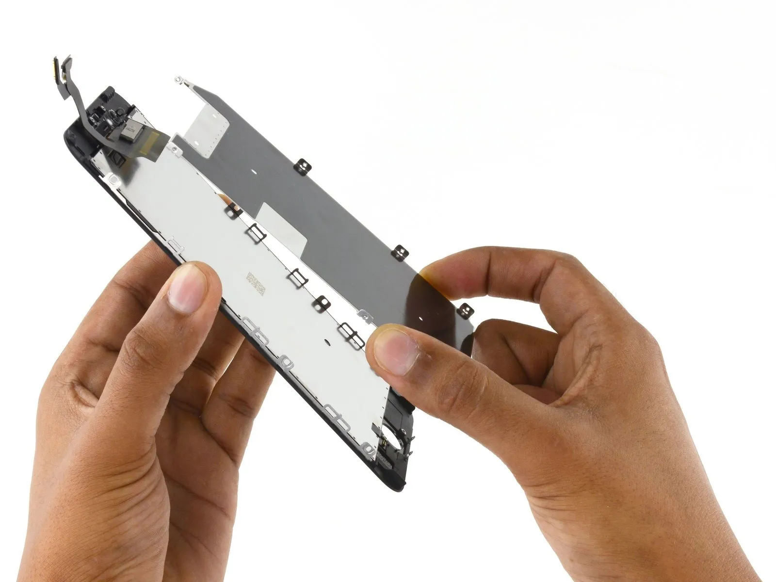
Step 42 | LCD and Digitizer

- The liquid crystal display and its associated touch sensor component are retained.
- The Touch ID feature will EXCLUSIVELYoperate correctly when paired with the phone's initial home button assembly; therefore, transferring the home button assembly from the old display assembly to the new one is essential to maintain Touch ID functionality.
- To ensure proper operation, wipe the touchscreen’s exterior with an alcohol-based cleaning solution before reactivating the iPhone, as this process effectively reduces any residual static charge that could potentially interfere with the display's performance.
- Before powering on the iPhone after reassembly, establish a connection to an alternating current power source. Following successful boot-up, the AC power connection can then be safely removed.