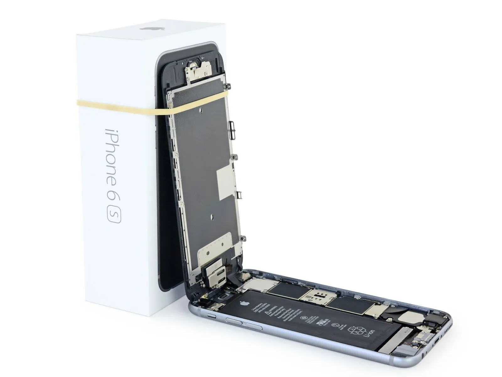
iPhone 6s Wi-Fi Diversity Antenna Replacement
Using the instructions provided, substitute the iPhone 6s’s Wi-Fi diversity antenna.
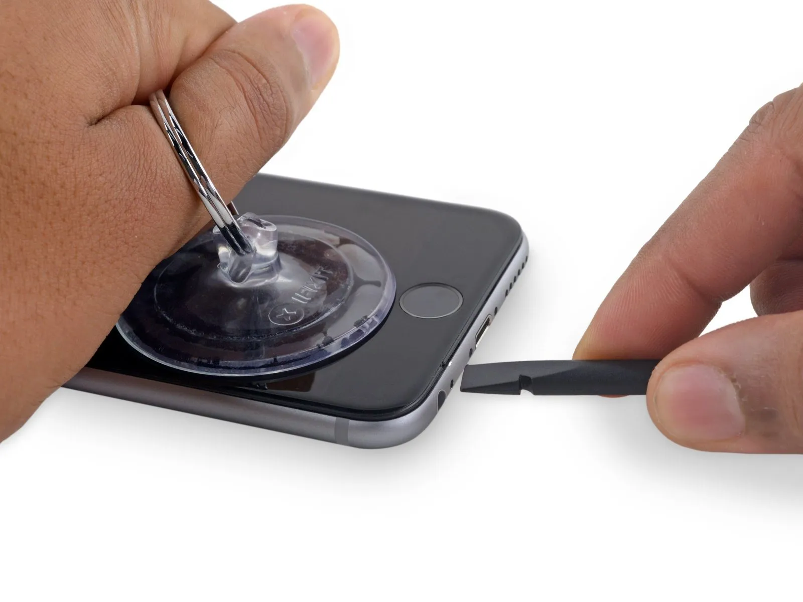
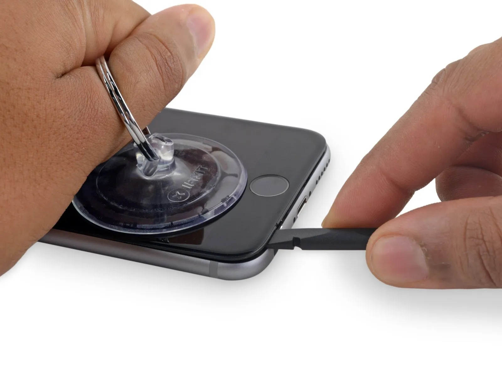
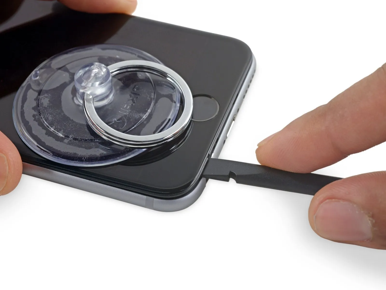
Step 1 | SIM Tray
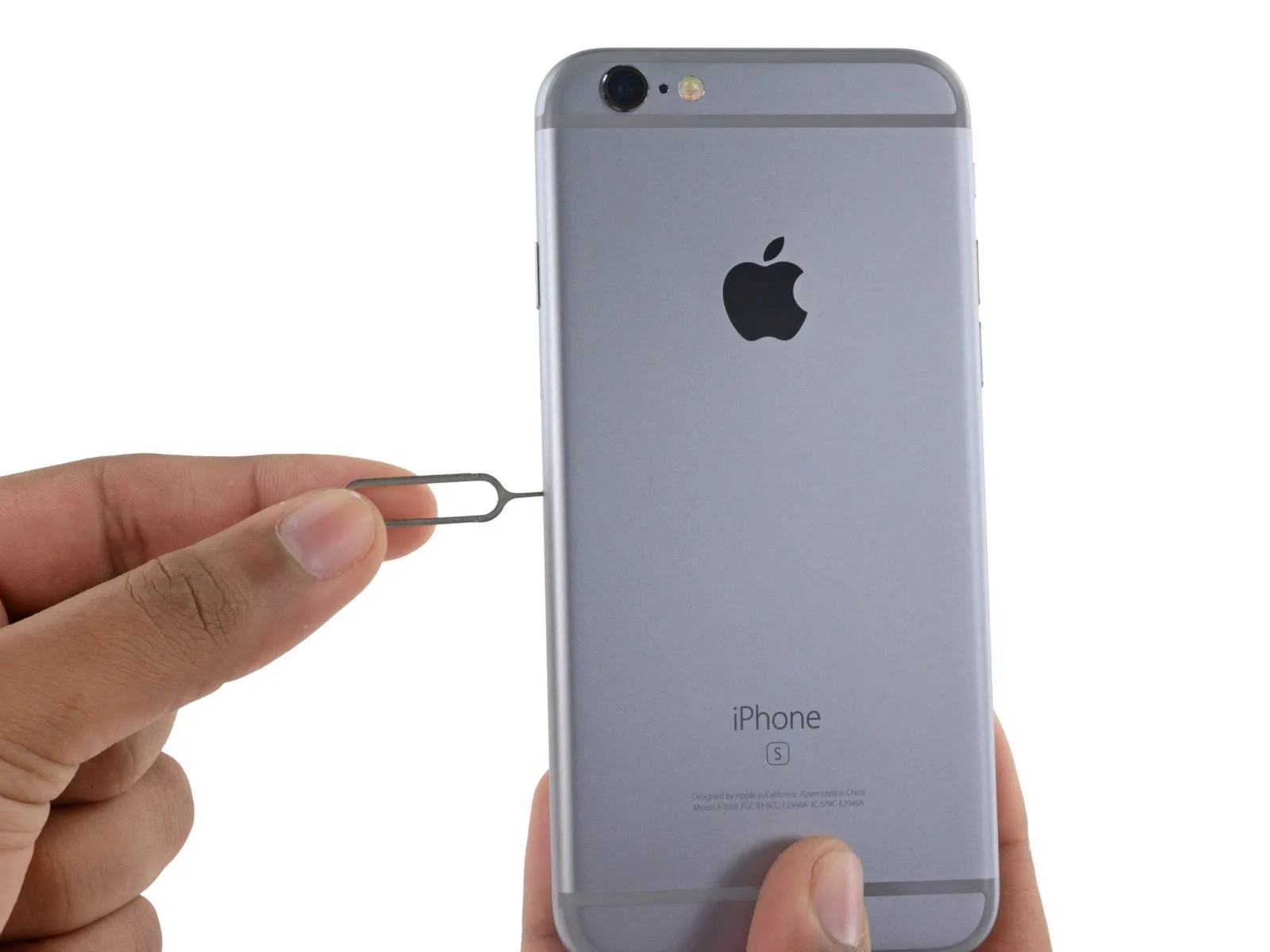
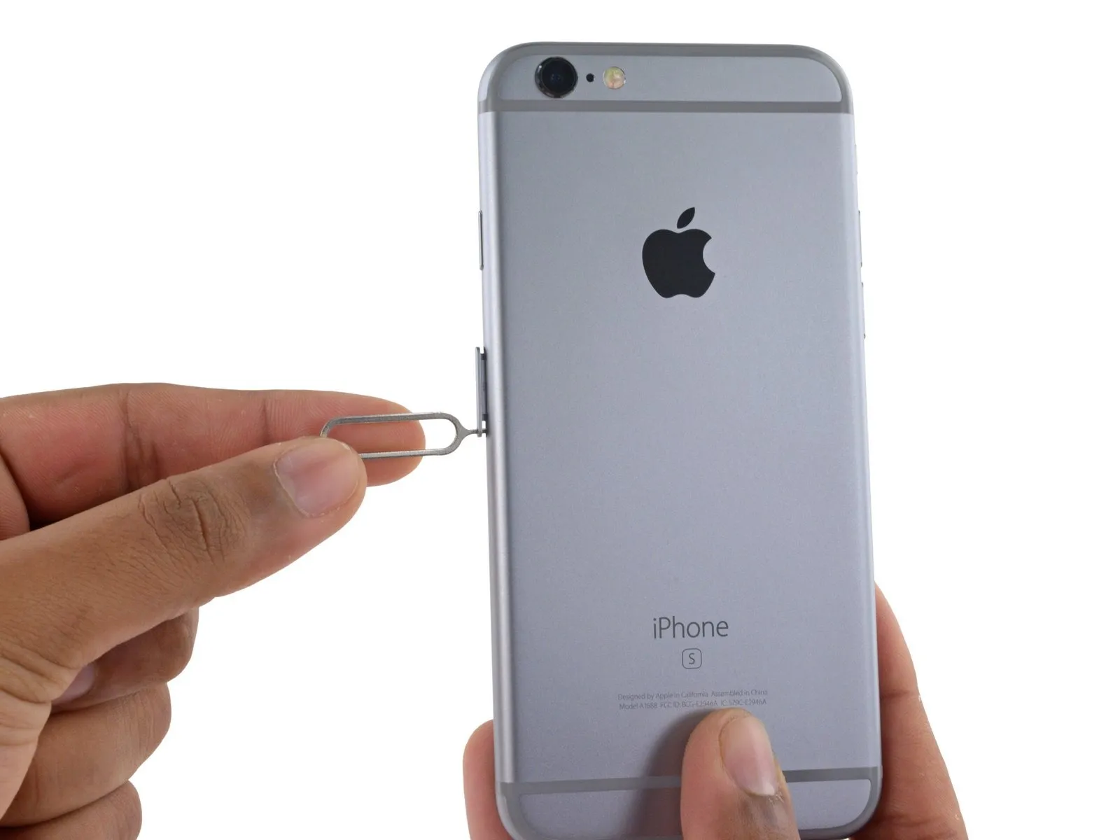
Apply force to release the tray from its housing.
Applying considerable pressure might be necessary.
Step 2
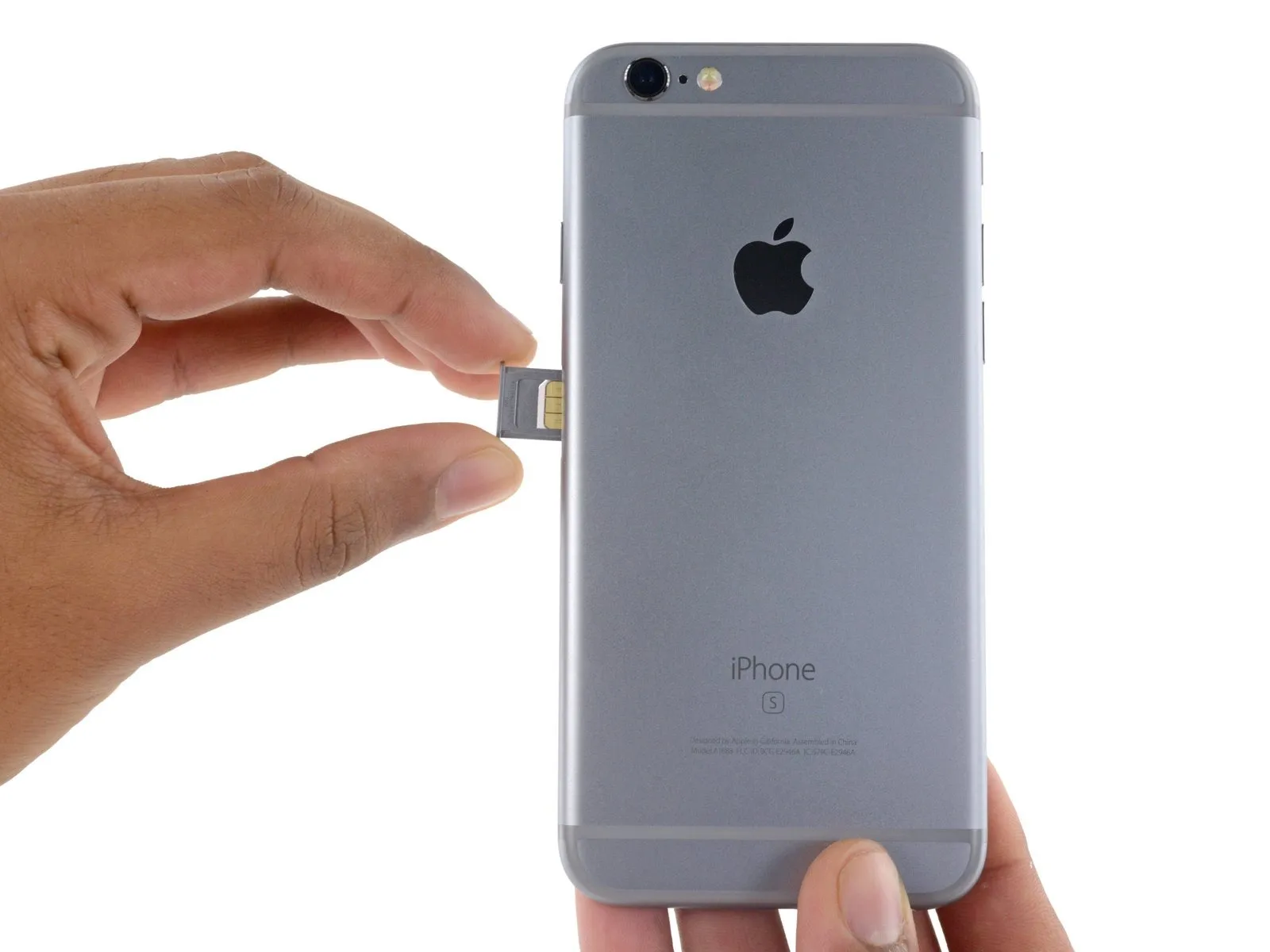
Confirm the SIM card's alignment within the tray before sliding it back in, matching its position to the tray's design.
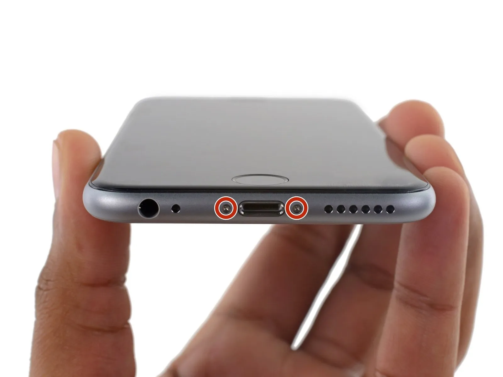
Step 3 | Pentalobe Screws
To prevent electrical shock or damage, ensure the iPhone is completely de-energized prior to starting the repair process.
Using appropriate tools, detach the two 3.4 mm P2 Pentalobe screws located along the iPhone's lower edge, positioning them on both sides of the Lightning connector.
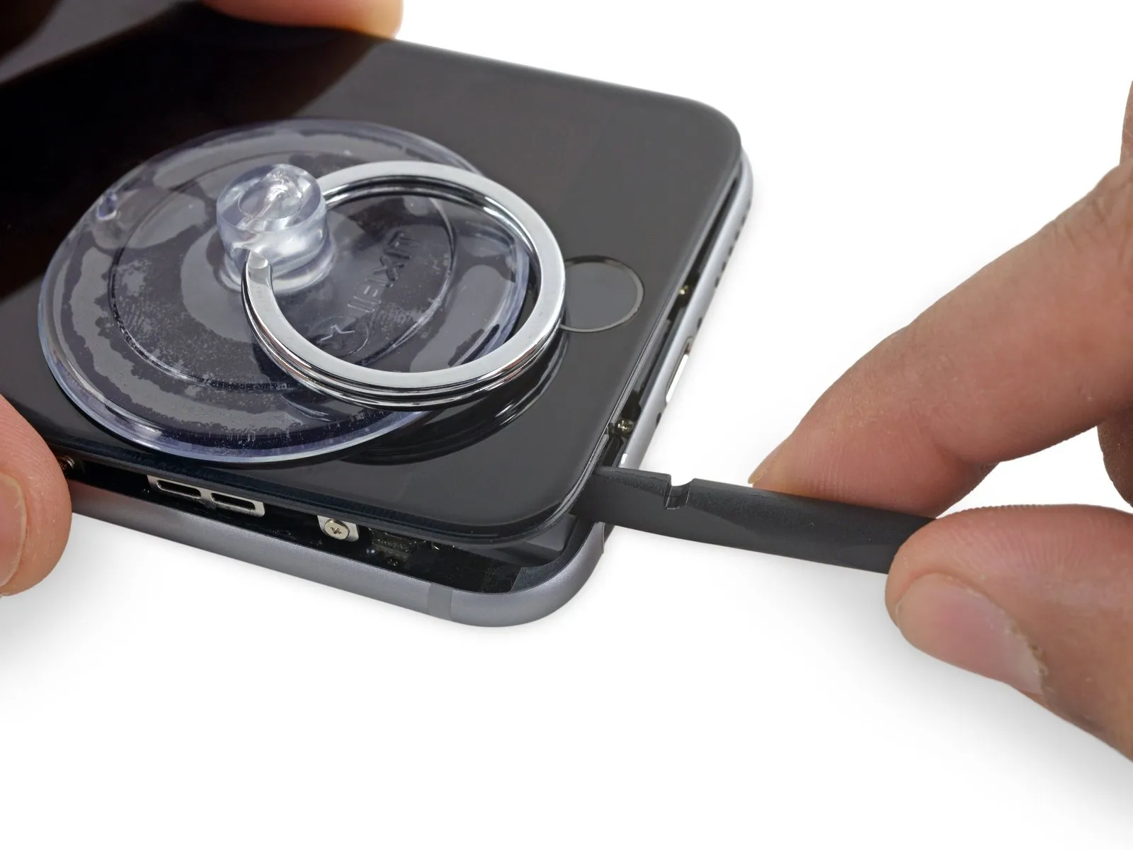
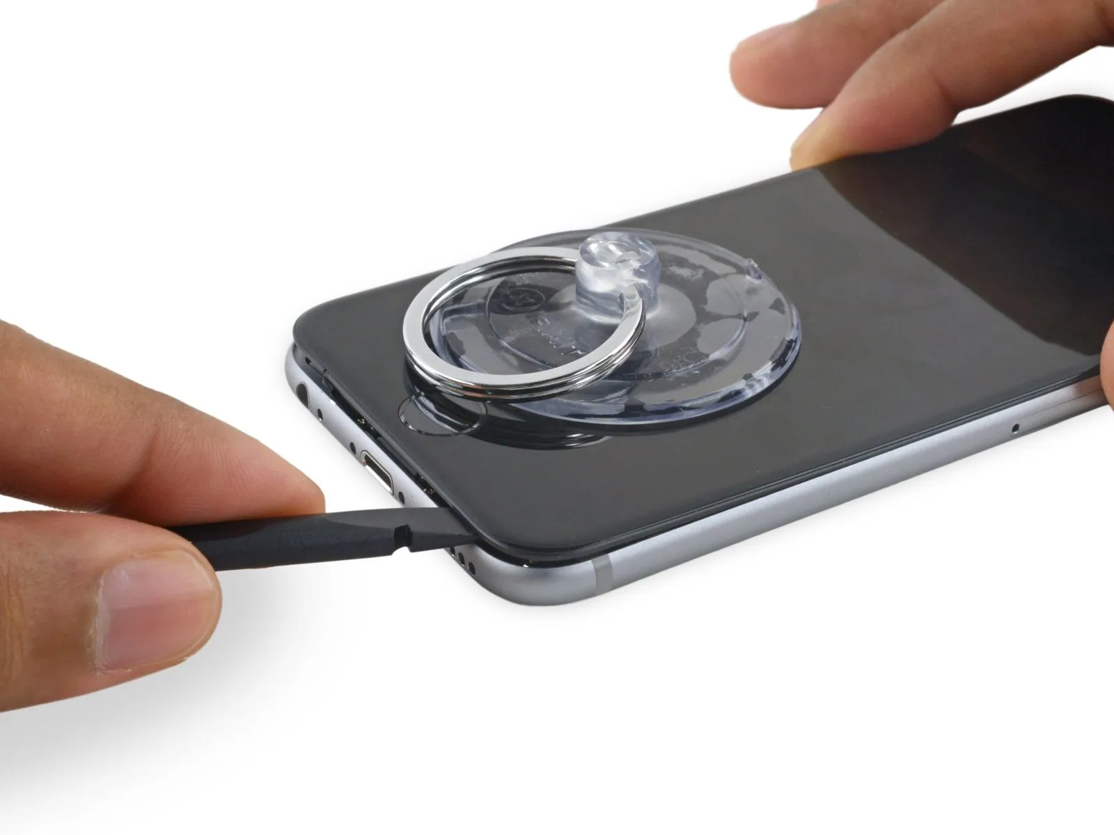
Step 4 | Anti-Clamp instructions


Refer to the included guide for detailed procedures regarding Anti-Clamp operation.
To release the Anti-Clamp's arms, move the blue handle in a rearward direction.
Position the arms so they clear the left or right side of the iPhone, then move them into place.
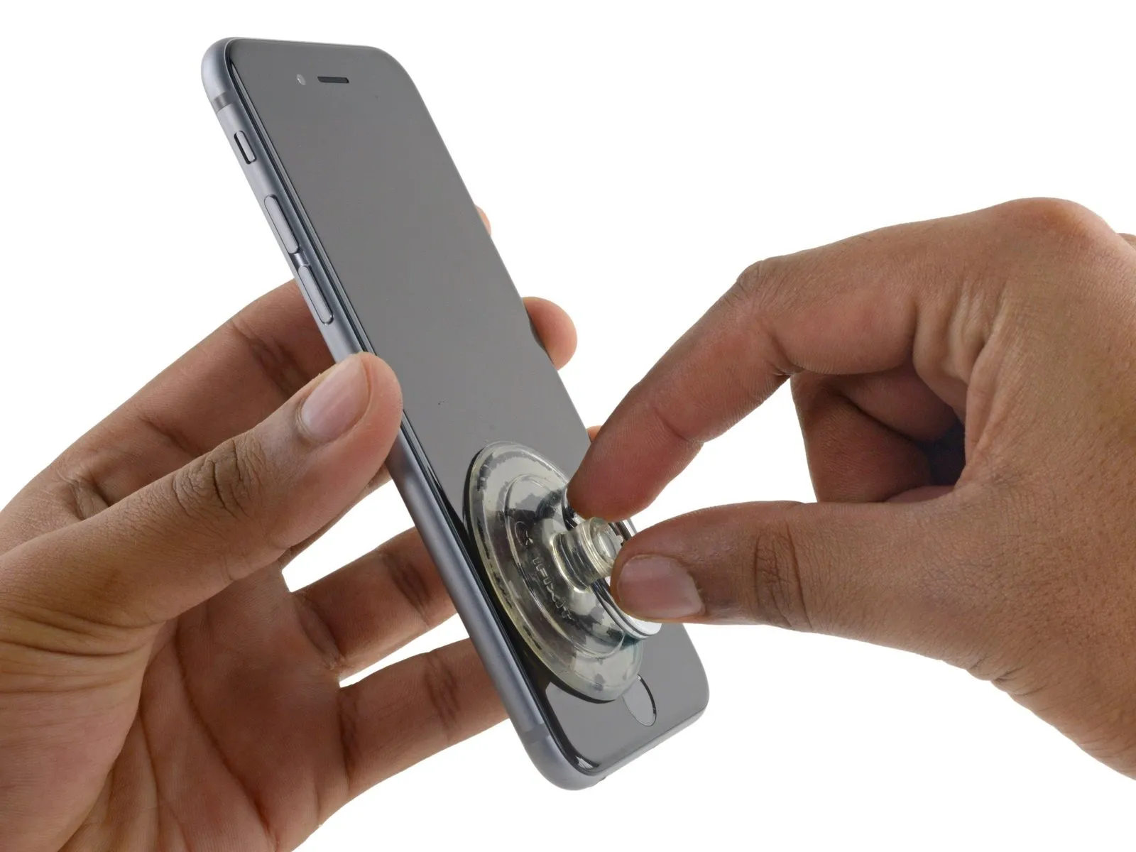
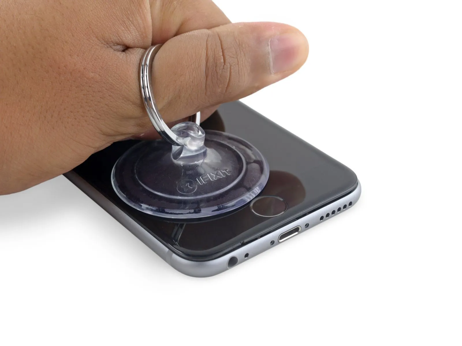
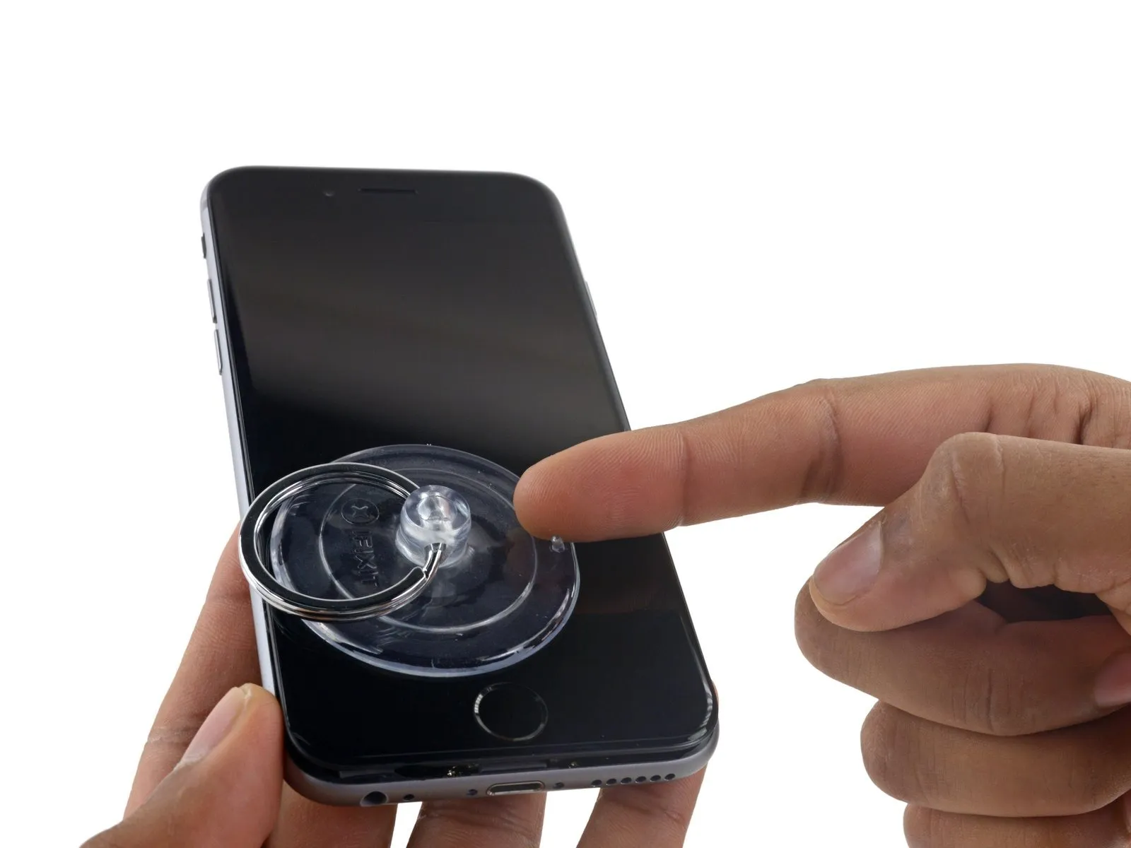
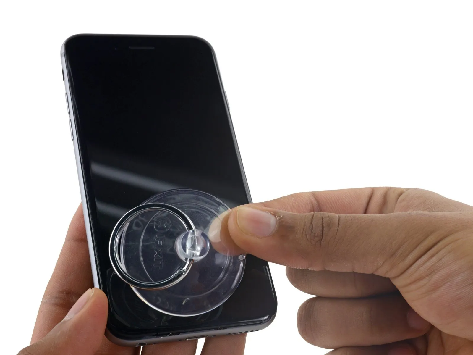
Affix two suction cups—one to the front surface and one to the rear—close to the lower edge of the iPhone, situated directly above the home button.
Apply vacuum by pressing the cups firmly against the surface you intend to work on.
To improve the Anti-Clamp's adherence if the iPhone's exterior feels excessively smooth, apply tape to the device's surface to increase friction.
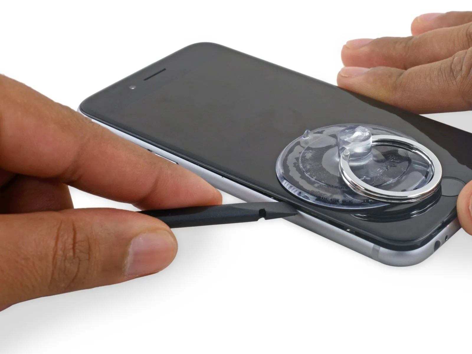
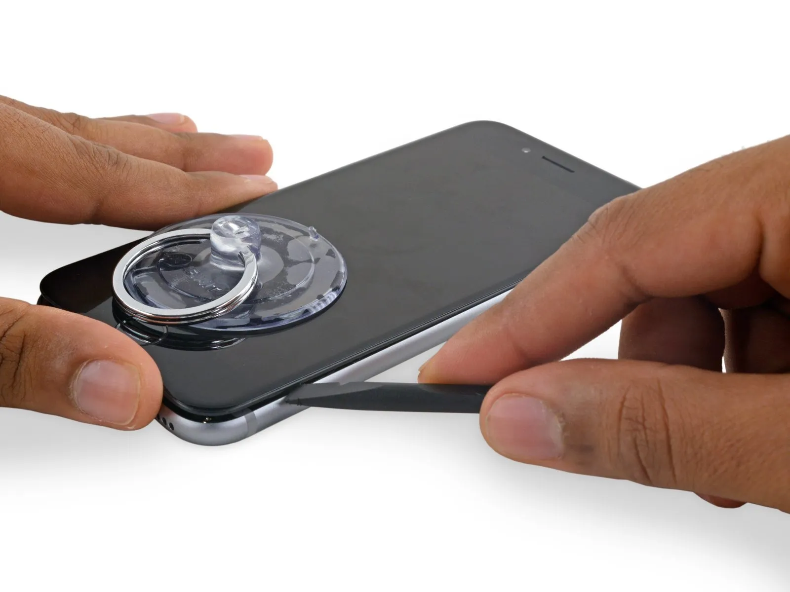
Step 5


Rotate the handle fully, completing a full 360-degree turn, observing for the initial expansion of the cups.
Maintain parallel positioning of the suction cups; should misalignment occur, gently release the suction cups' hold and reposition the arms.
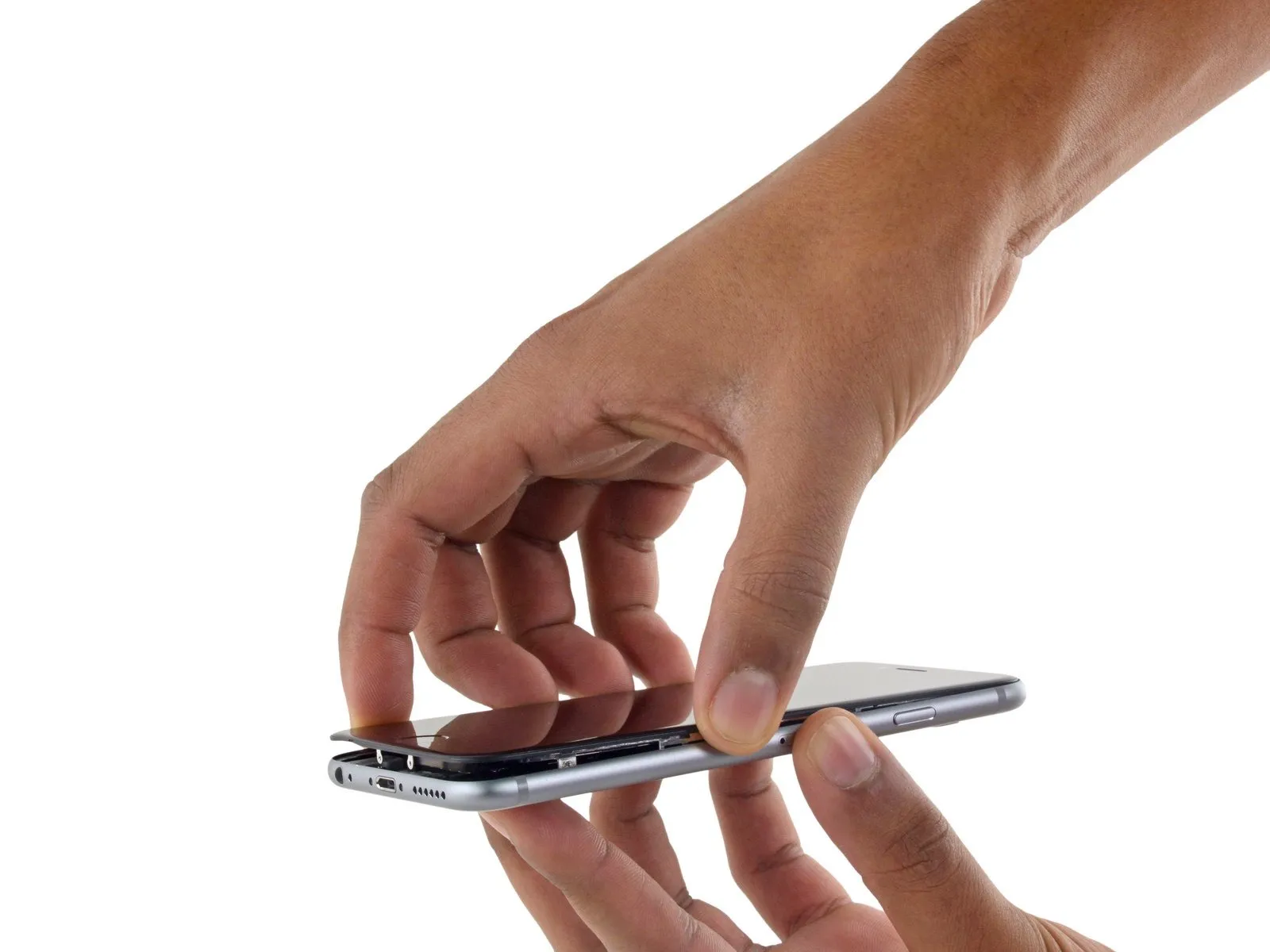
Once sufficient separation is achieved by the Anti-Clamp tool, slide a prying tool beneath the display panel.
To ensure adequate separation, reposition the handle by 90 degrees.
Allow the Anti-Clamp device to function and permit several seconds of inactivity following each incremental adjustment, limiting each rotation to a maximum of 90 degrees.
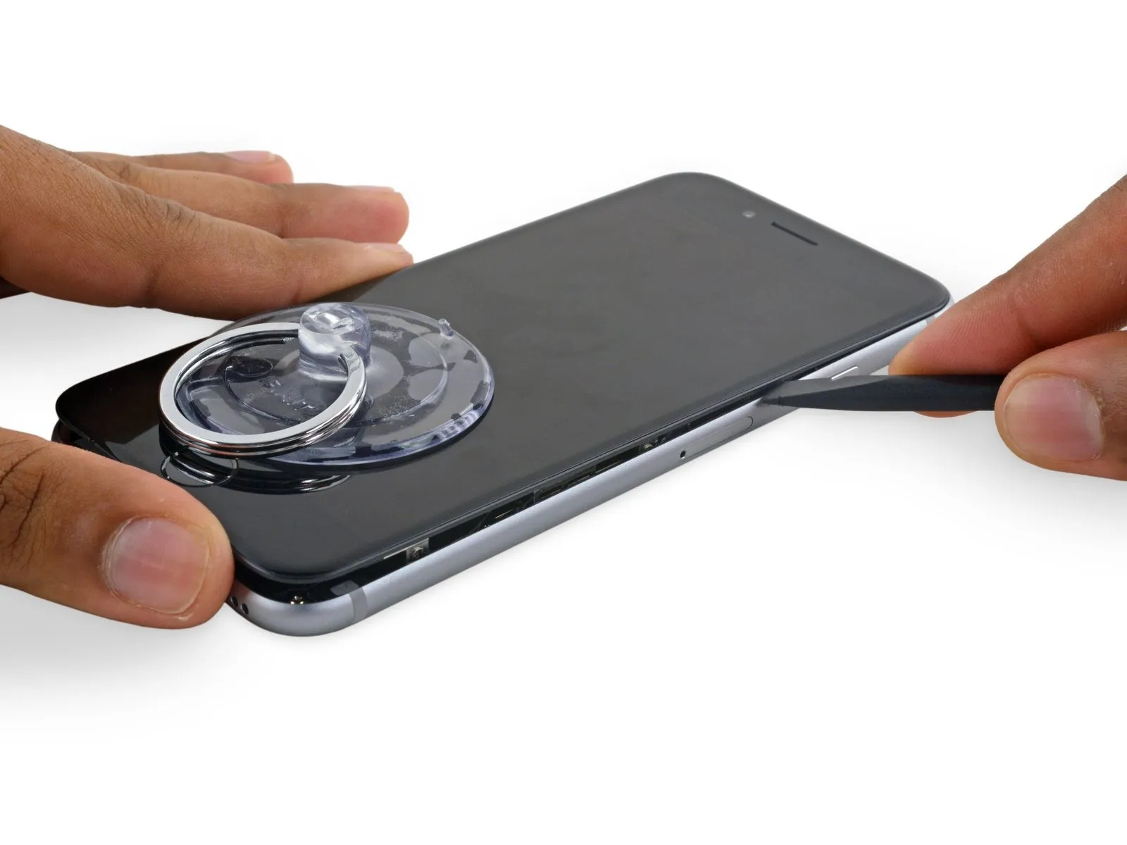
Step 6 | Opening Procedure
Using a hair dryer or iOpener, gently warm the bottom edge of the iPhone’s casing with moderate heat for approximately 60 seconds.
Applying heat will loosen the adhesive that holds the display in place, facilitating separation.
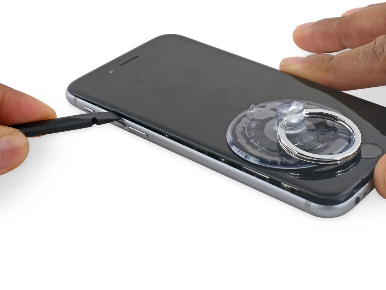
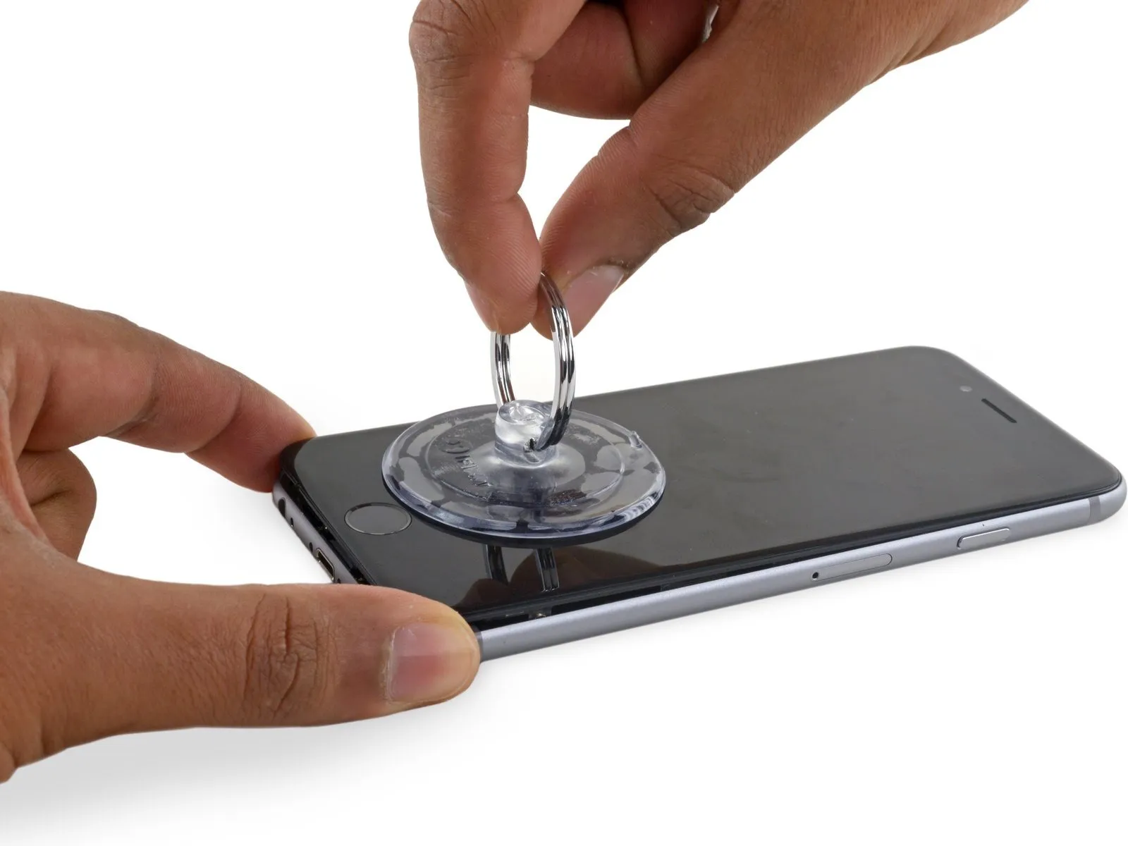
Step 7
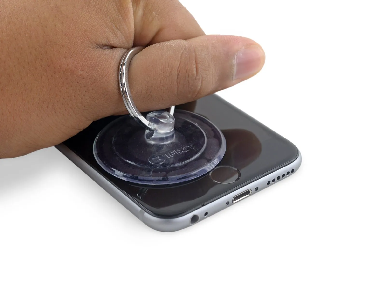
Using a suction cup, secure its surface to the display assembly's lower left corner.
Avoid positioning the suction cup directly on the home button.
To facilitate suction cup attachment on a severely cracked display, apply a sheet of clear packing tape across the damage; if that proves ineffective, utilize a robust adhesive tape as a direct substitute for the suction cup. As a last resort, secure the suction cup directly to the fractured screen using superglue.
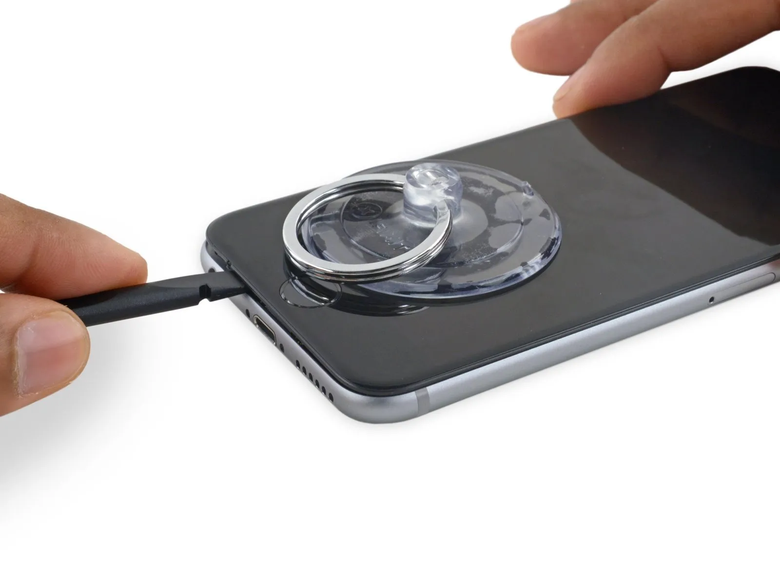
Step 8
Exercise caution and use steady, even pressure when installing the display assembly, as it requires a snug fit and is secured with adhesive.
To avoid display assembly damage, use minimal force when separating it from the rear case; the goal is to establish a narrow separation.
To ease separation of the display adhesive, apply warmth to the iPhone’s front surface with an iOpener, hair dryer, or heat gun until the exterior reaches a temperature just beyond comfortable touch.
Step 9
Using a spudger, insert its flat side into the separation between the display and the back cover, positioning the insertion point immediately over the headphone jack.
Step 10
Step 11
Using a spudger, carefully work along the phone's edge to loosen the adhesive bond and release the retaining clips.
Step 12
Using a spudger, gently move it horizontally across the phone's lower border.
Step 13
Step 14

To prevent damage, limit the display's opening angle to a maximum of 90 degrees; the three cables connecting it to the top edge are susceptible to breakage if extended beyond their natural length.
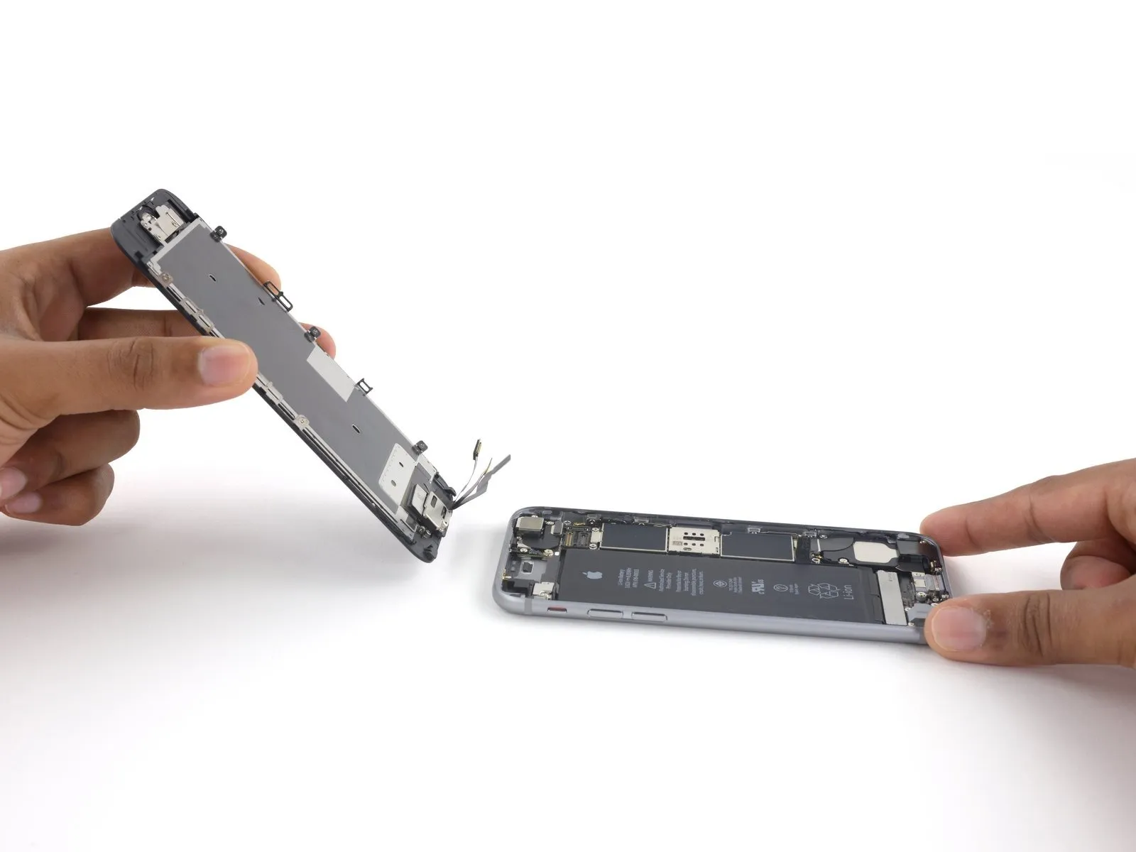
Step 15
Step 16
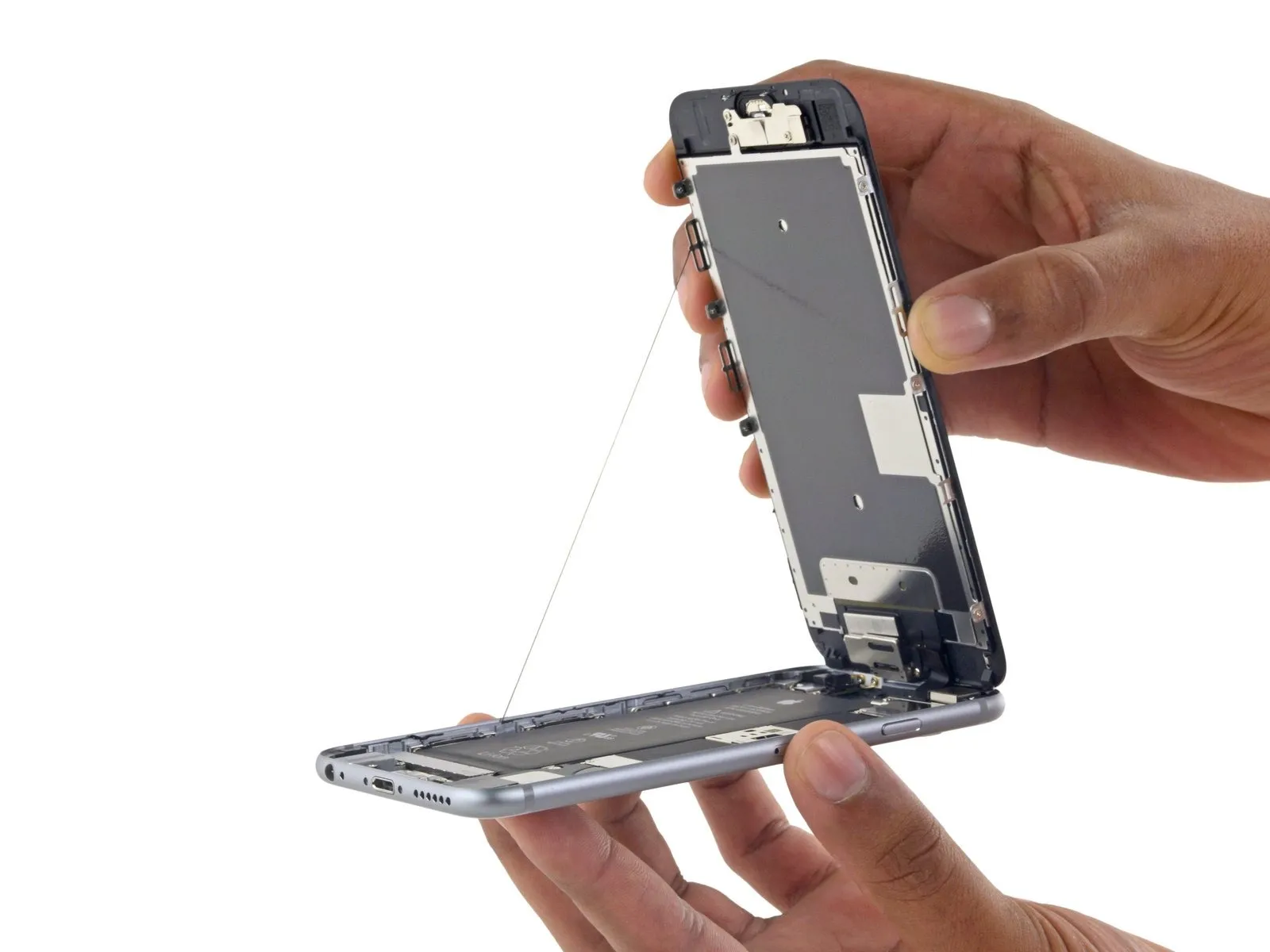
- Employing a careful touch, raise the display assembly by leveraging the front panel's top clips to act as a pivot, thus separating the phone's components.
- Carefully position the display at a 90-degree angle, then secure it in a supported position to prevent movement during the repair process.
- To avoid stressing the display's wiring during the repair process, secure it with a rubber band.
- As a temporary substitute, an unused, sealed can of soda can be employed to secure the display in place.
- If you intend to substitute fresh adhesive along the display's perimeter during reassembly, stop at this point.
- To ensure proper alignment during reassembly, position the camera-side edge of the screen body beneath the main body's edge. Then, guide the screen frame's hooks beneath the main body's rim, drawing them taut towards the camera end to facilitate cover closure and secure clipping.
- Ensure these clasps, which function as a substitute for a hinge, are positioned correctly beneath the phone's outer frame edge. This placement allows the screen to smoothly return to its closed position, resulting in a gentle, secure snap.
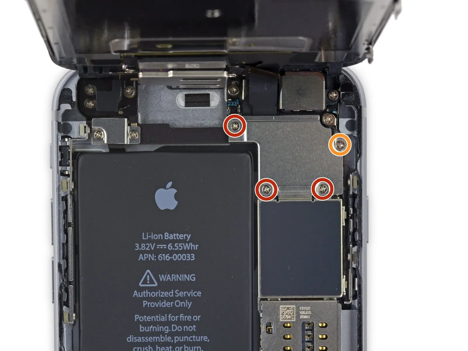
Step 17 | Battery Connector
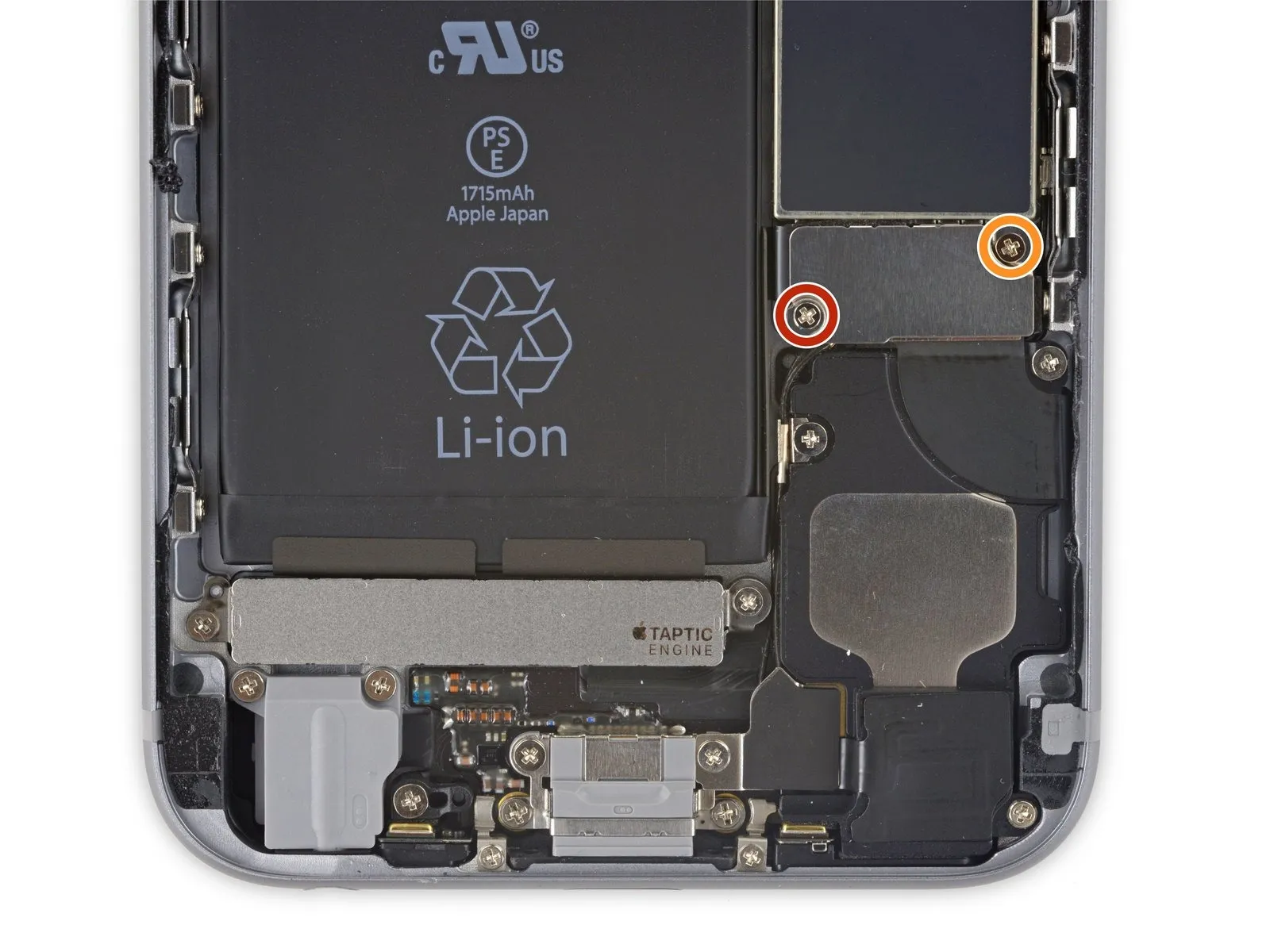
Using a Phillips screwdriver, detach the two screws—each measuring the same length—that hold the battery connector bracket in place.
- A screw with a 2.9 mm diameter is required.
- A screw with a 2.2-millimeter head diameter is required.
Carefully note the location of every screw during disassembly, as reassembly requires placing each one in its original position to prevent iPhone damage.
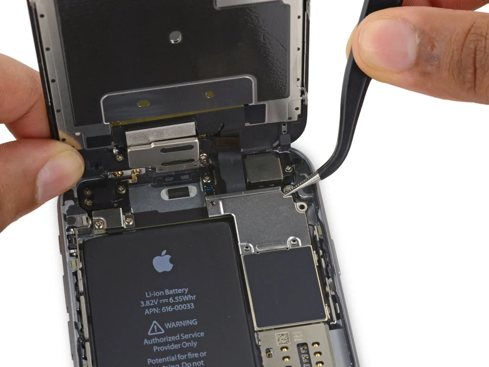
Step 18
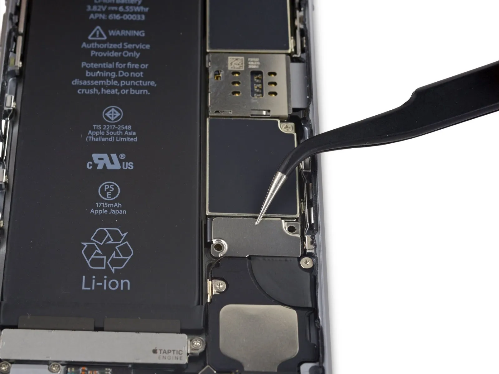
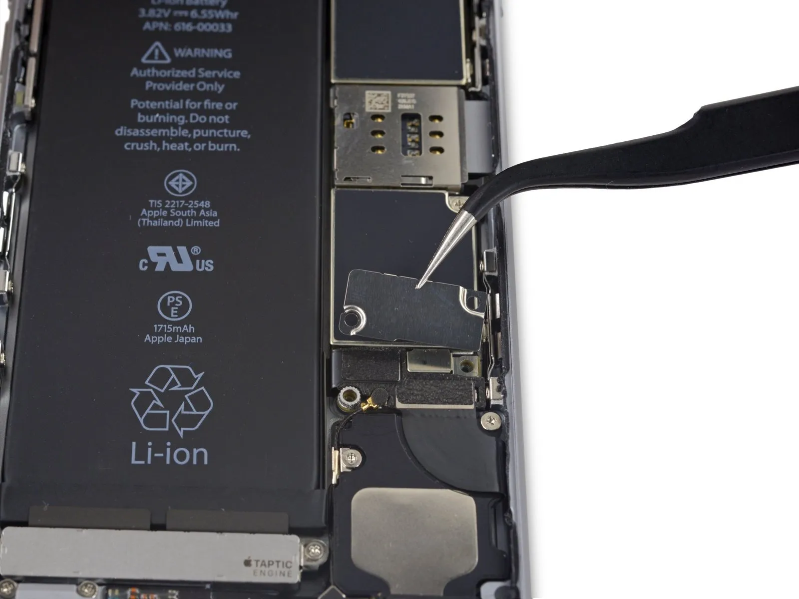
Using a 5mm hex screwdriver, detach the bracket securing the battery connector.
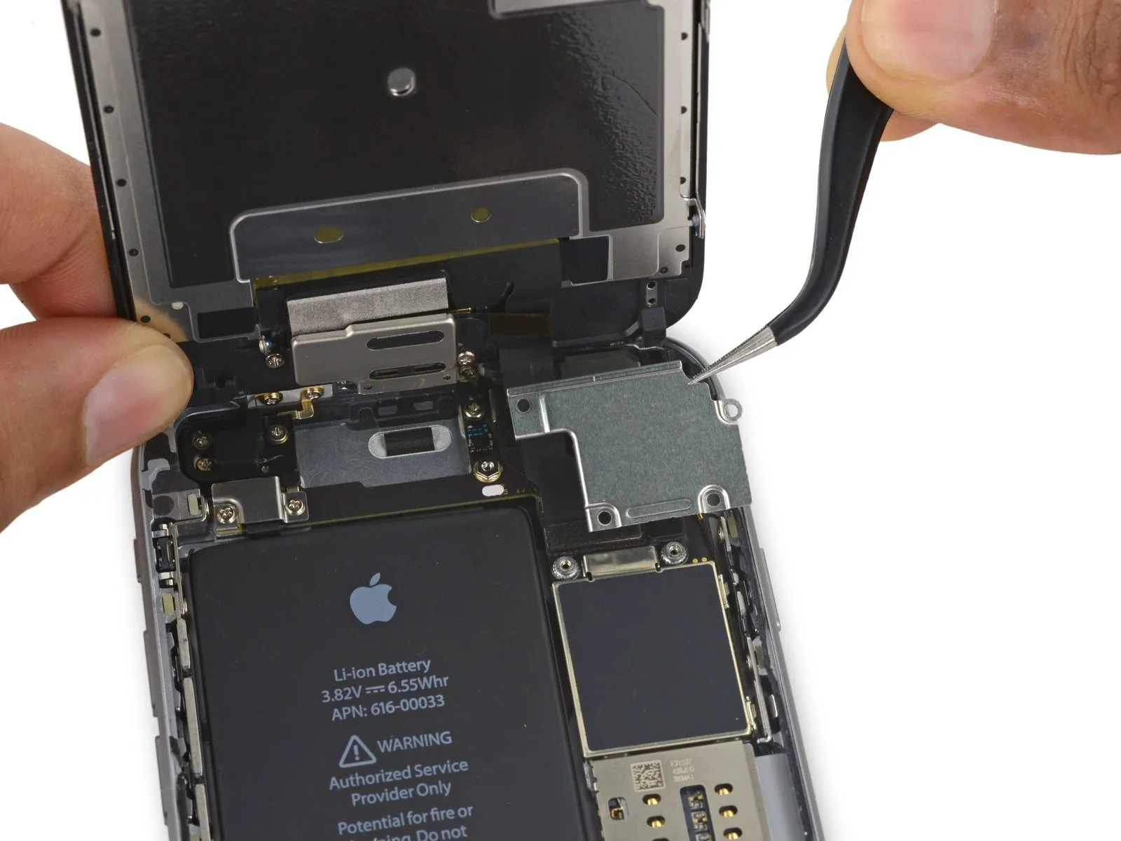
Step 19

Carefully separate the battery connector from the logic board by applying upward pressure with a spudger, ensuring the tool engages the connector's tip.
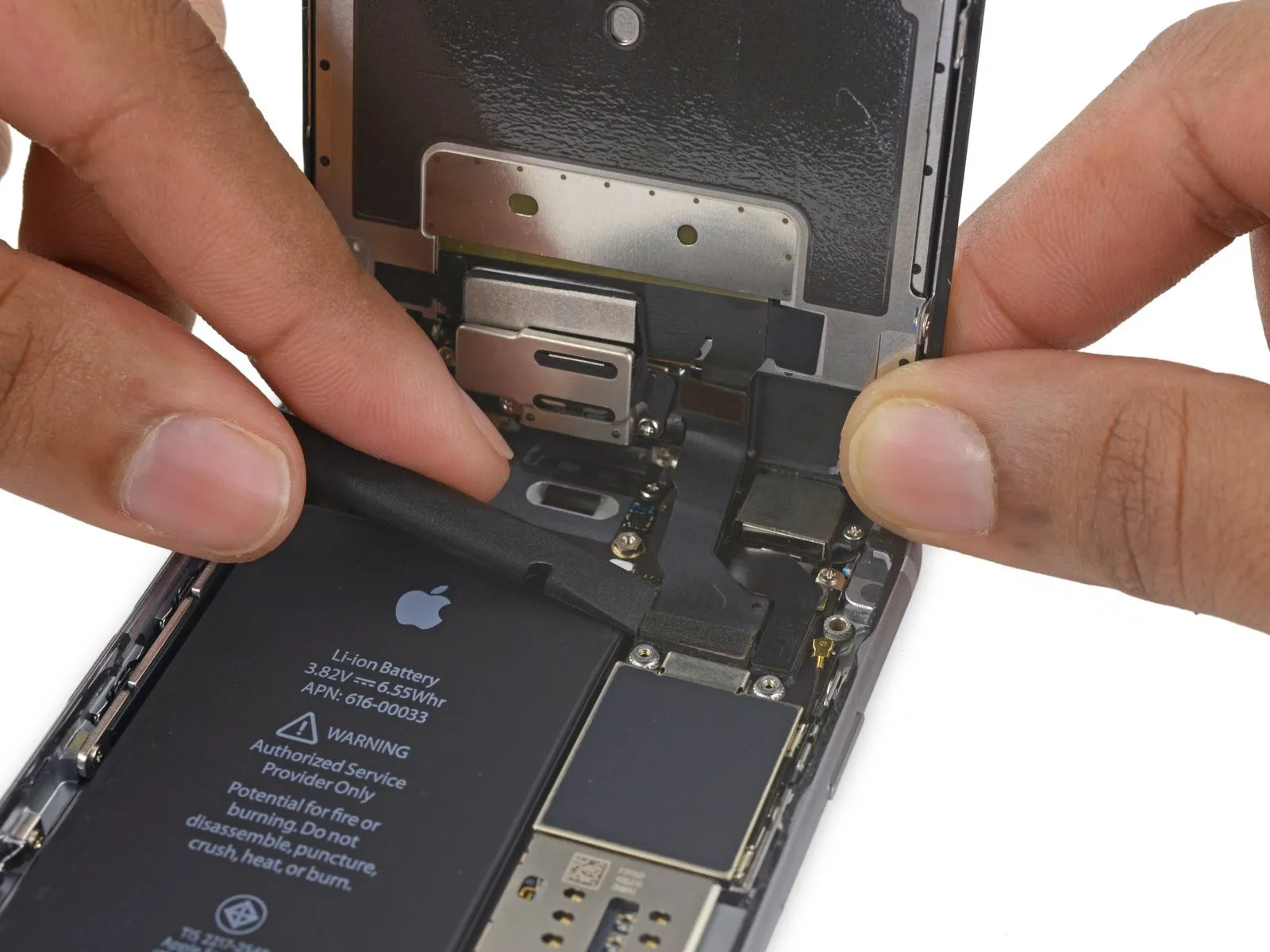
Step 20
To prevent unintended power-ups during the repair process, carefully detach the battery connector from its socket on the logic board, ensuring it remains disconnected.
Step 21 | Unfasten the display cable bracket
- Use three screws, each measuring 1.2 millimeters.
- A screw with a 2.8 mm diameter is required.
Step 22
Step 23
Step 24
To avoid potential digitizer damage or component bending, when reattaching the digitizer cable, apply pressure to opposing ends of the connector instead of the central area.
Step 25
Using a suitable tool, carefully lift the display cable vertically away from its connector on the logic board to release it.
Step 26
If you intend to substitute fresh adhesive along the display's perimeter during reassembly, stop at this point.
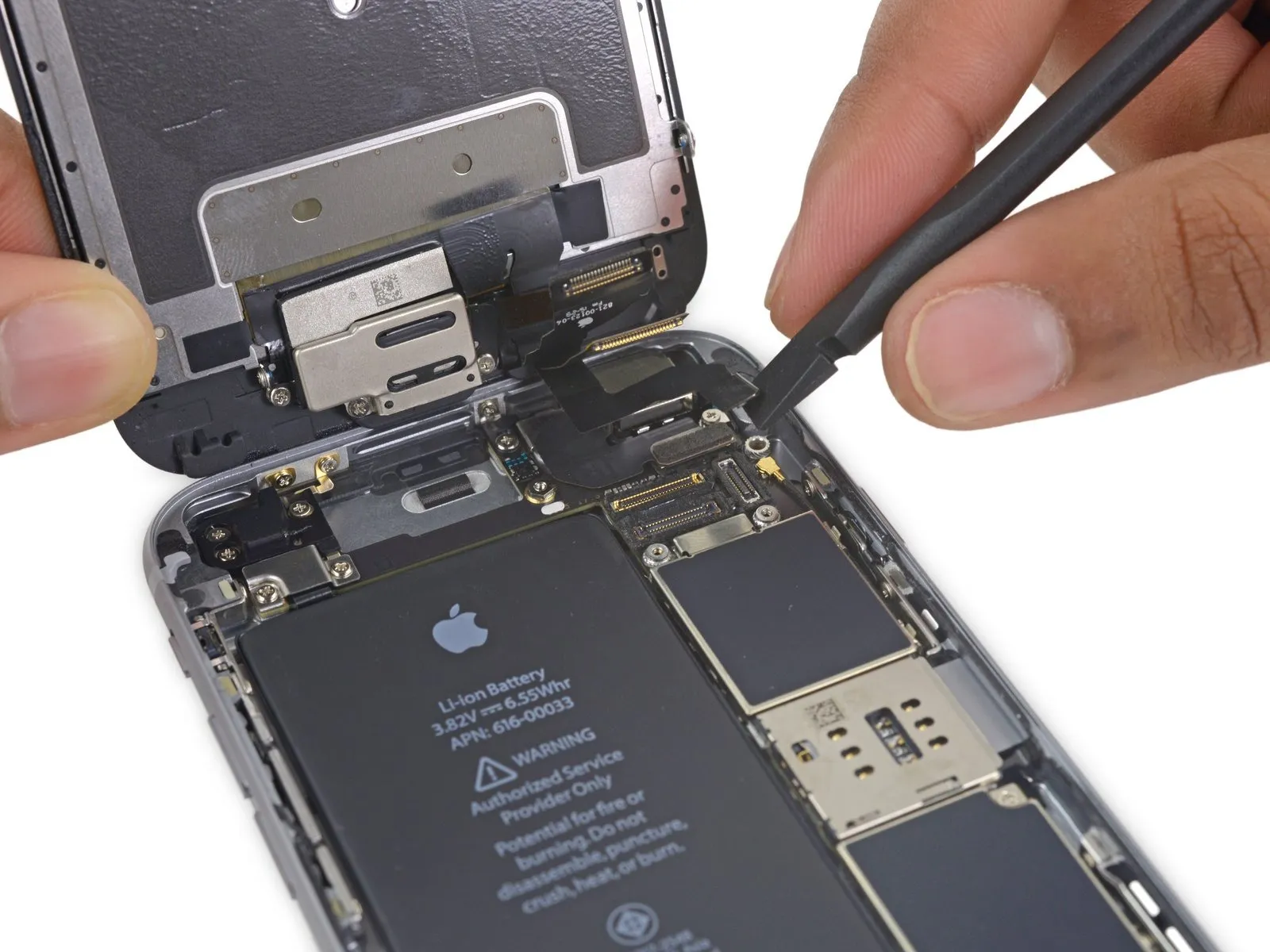
Step 27 | Speaker


Ensure the connector is properly positioned relative to the socket, then gently apply pressure with the spudger’s flat end until you hear a click indicating it’s secured; if the connection doesn't engage, verify the alignment and avoid applying undue force.
Step 28


Step 29
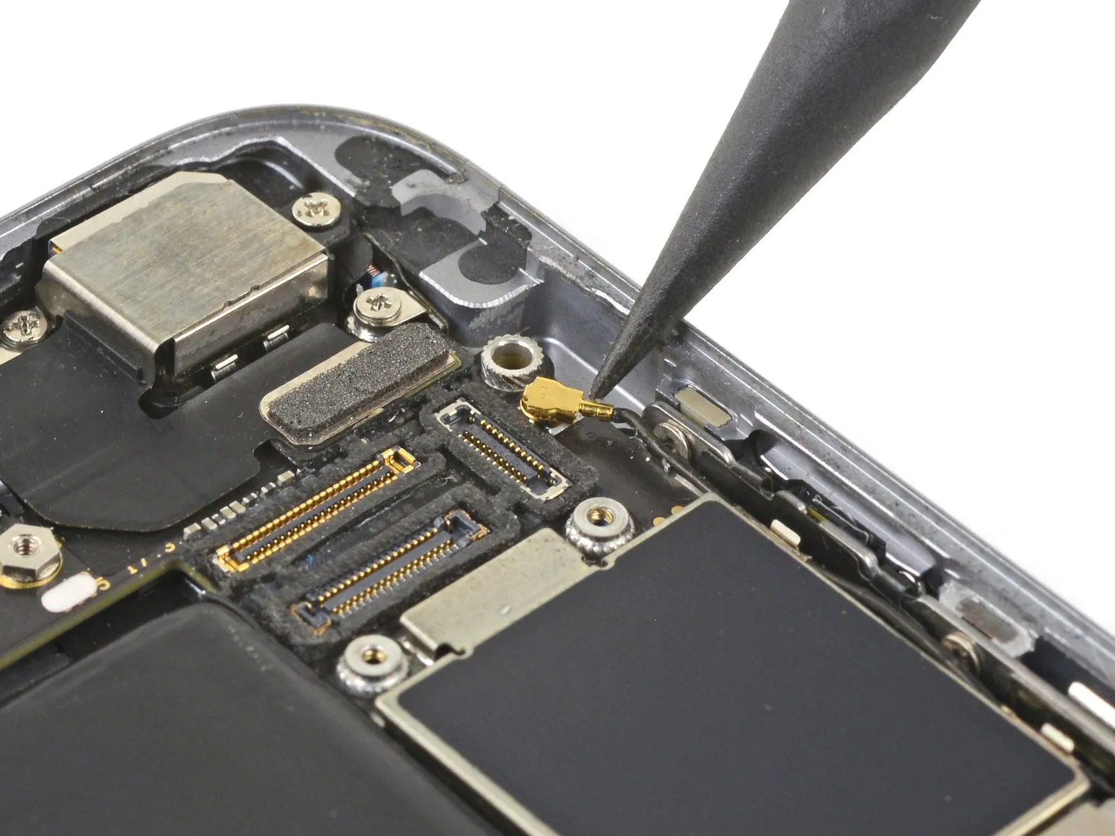
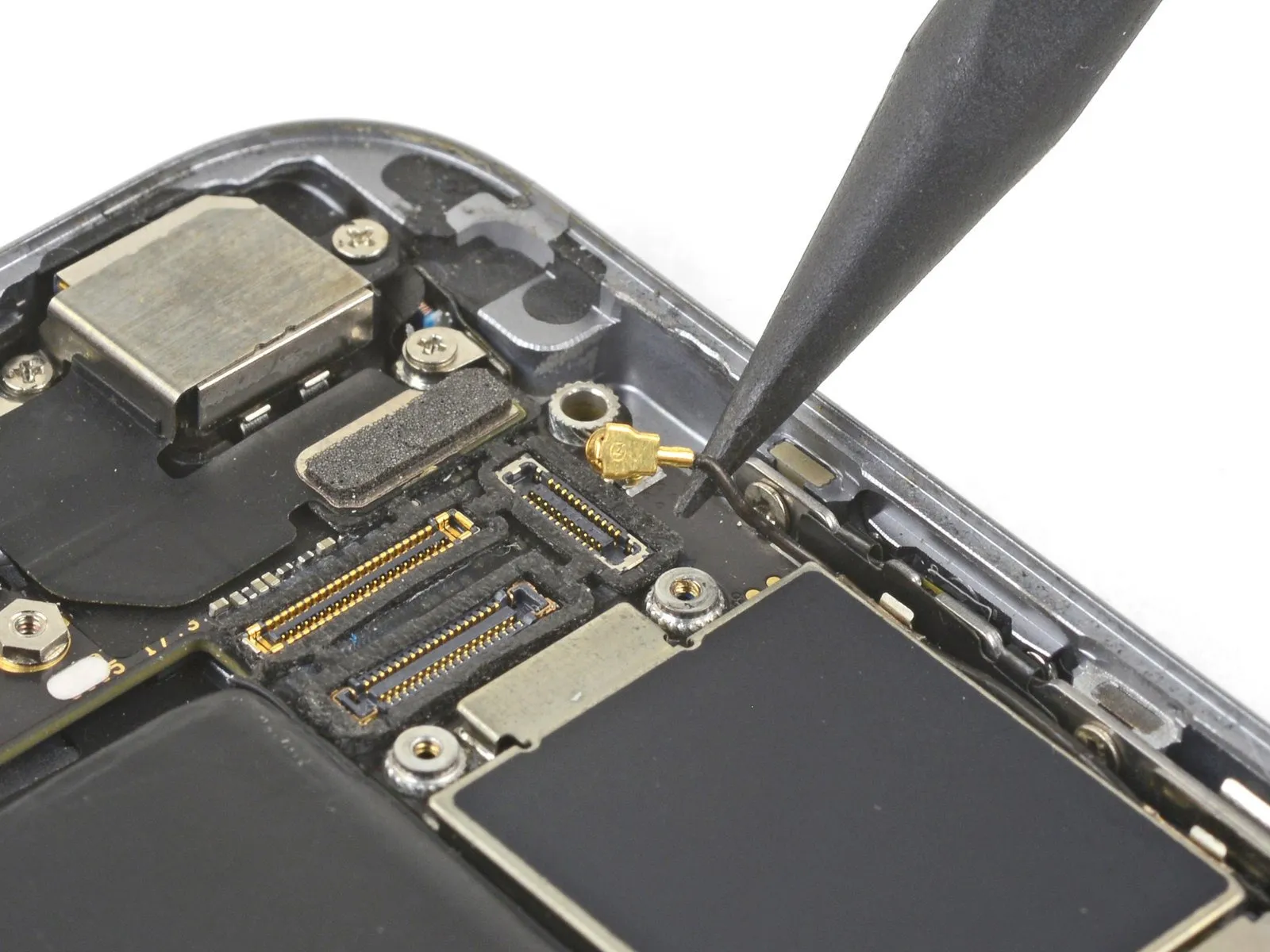
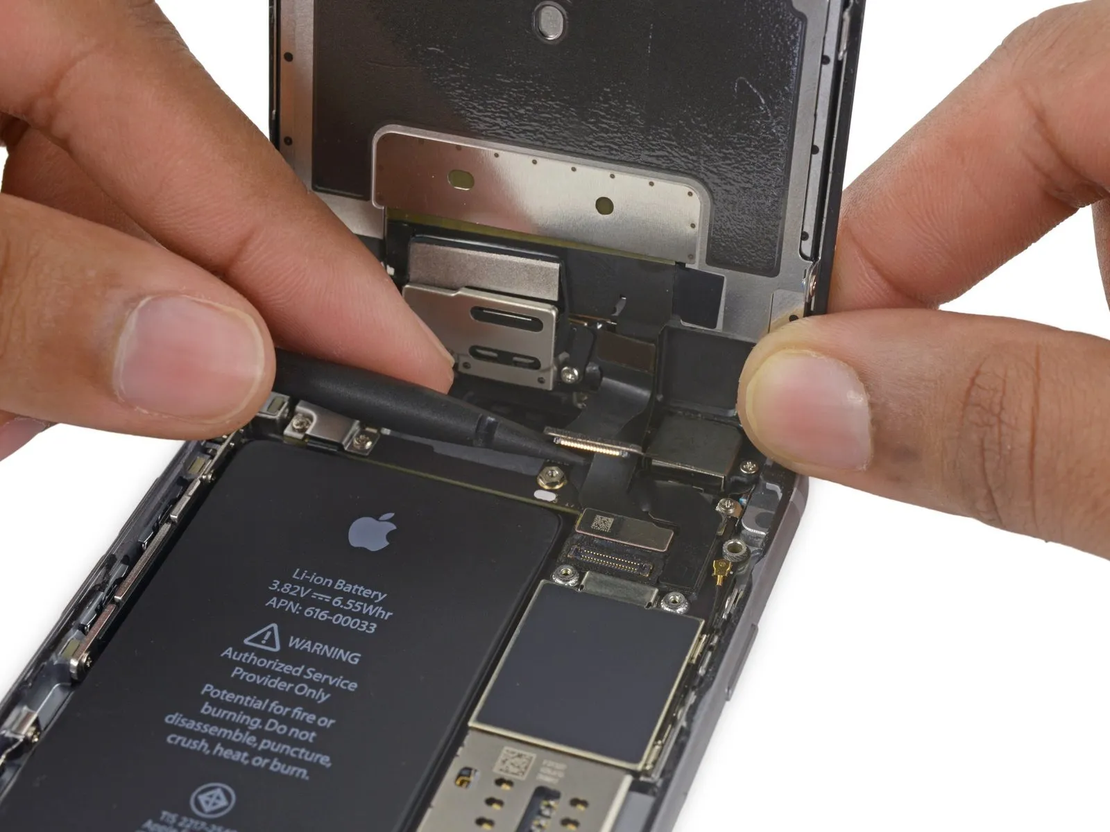
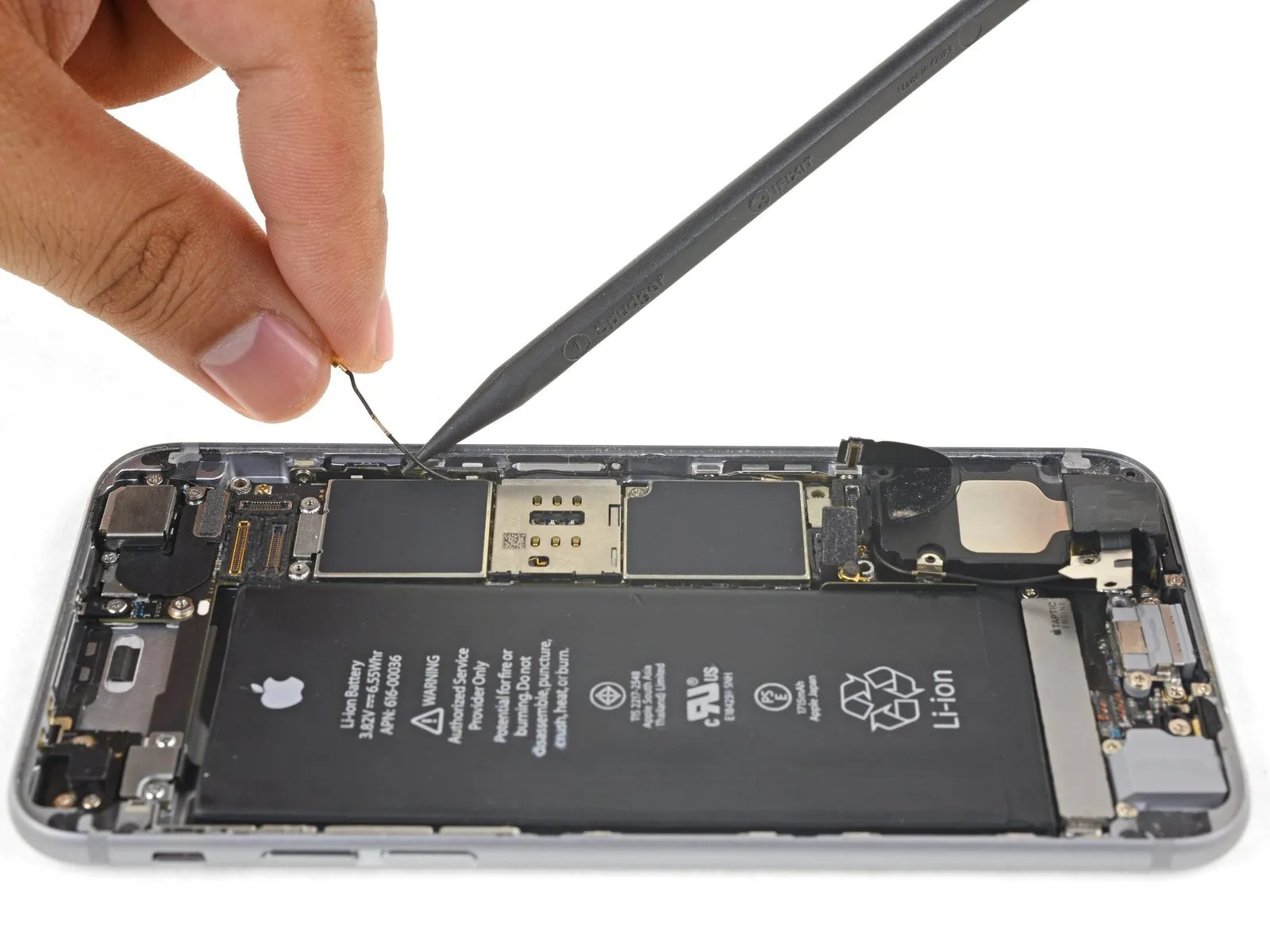
Carefully employ a spudger tip to separate and detach the antenna cable from its connector located close to the logic board's upper edge.
Step 30
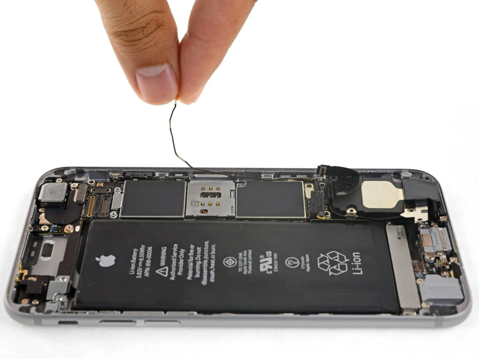
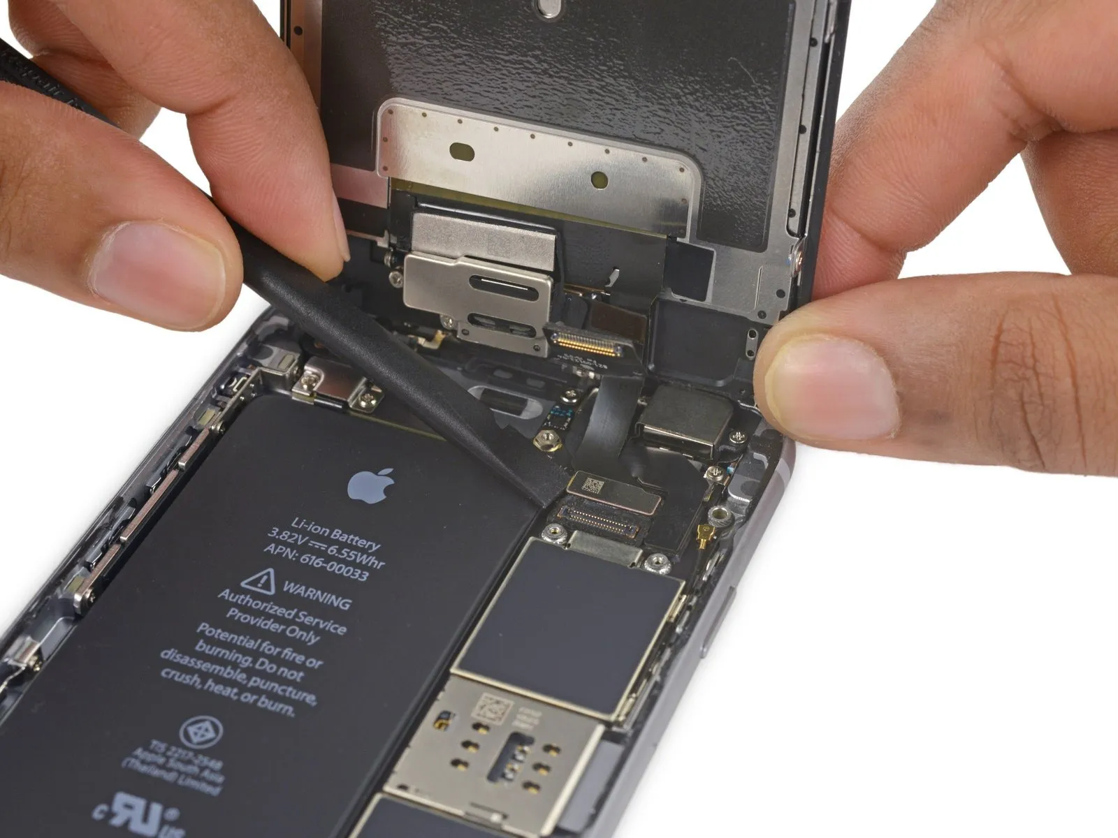
To allow sufficient clearance for the cable's upward movement, slightly reduce the tightness of the Phillips screw that holds the logic board in place, enabling it to move and provide additional space.
Ensure this screw is tightened again when putting the component back together.
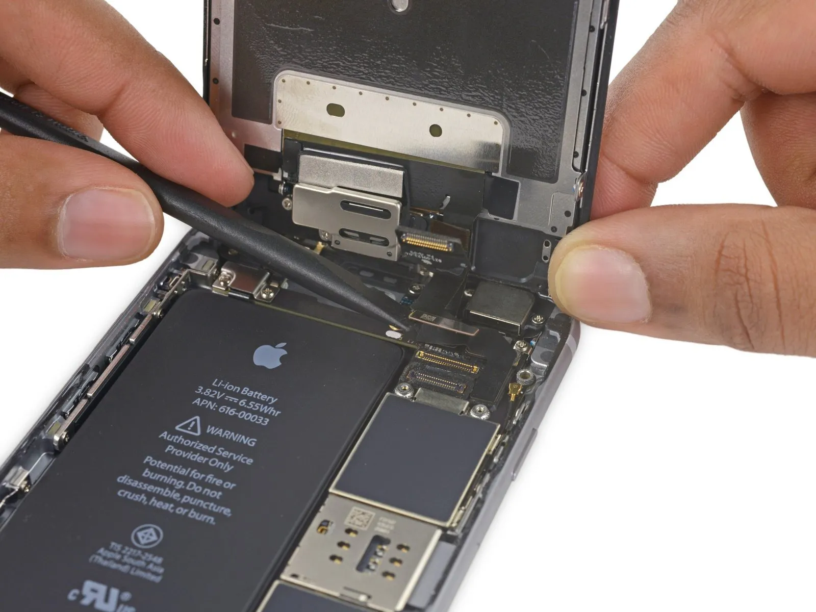
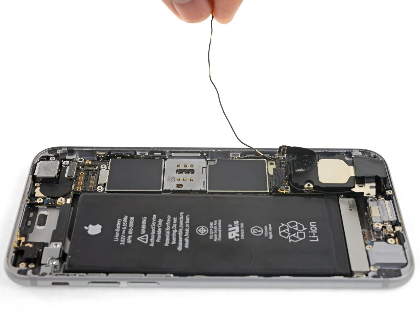
To ensure proper placement during reassembly, guide the antenna cable along the underside of the logic board's corner.
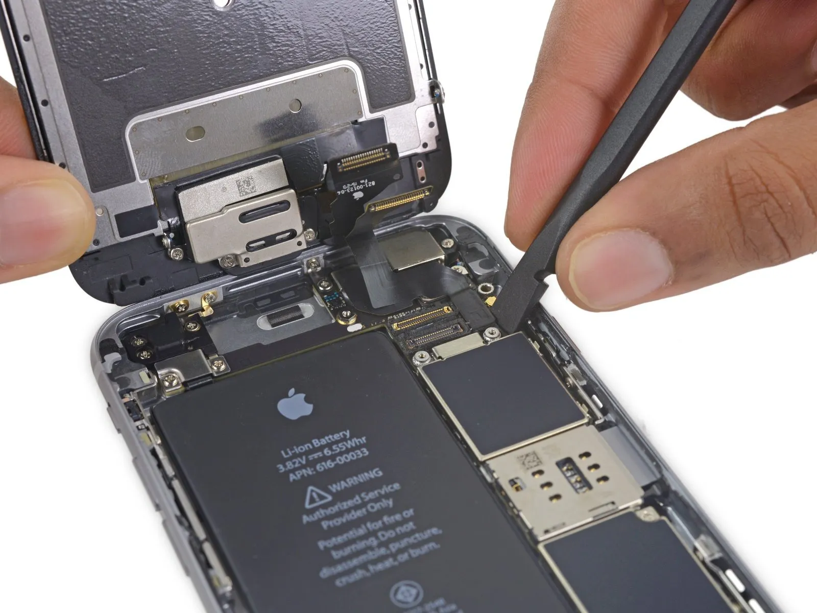
Following antenna cable rerouting, the SIM card tray can be reinstalled.
Should you encounter any impediment during movement, immediately cease and verify the antenna cable is not being obstructed by the tray.
Step 31
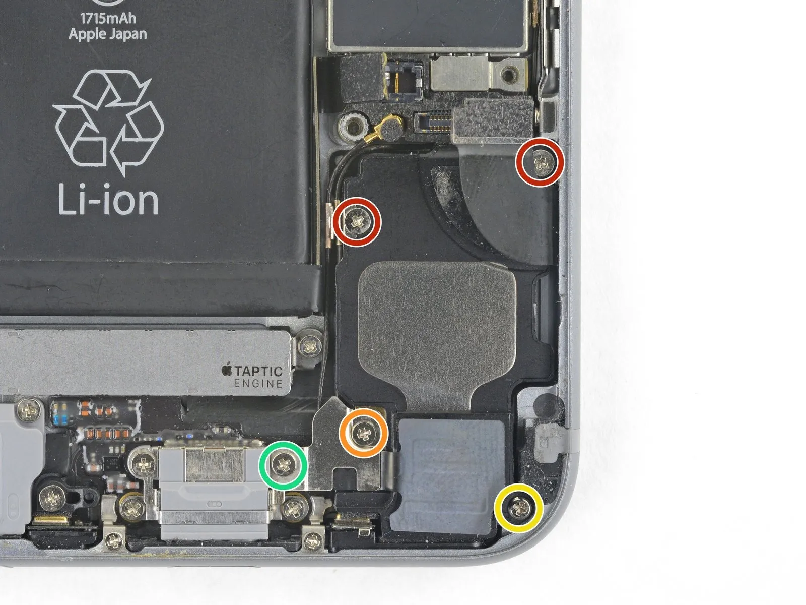
- Using a Phillips screwdriver, detach the speaker from the rear case by unscrewing the designated fasteners.
- Use two screws, each measuring 2.6 millimeters.
- A 2.3 mm screw, potentially obscured by tape, is required.
- Ensure you use the 2.3 mm screw, distinguishing it from the previous screw to prevent incorrect assembly.
- A screw with a 3.0-millimeter diameter is required.
Step 32
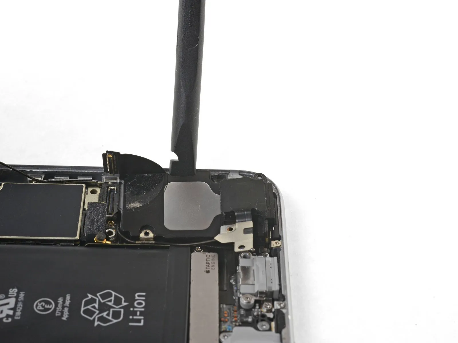
Using a spudger with a flat tip, carefully slide it into the gap located along the speaker module's side, where it meets the device's casing.
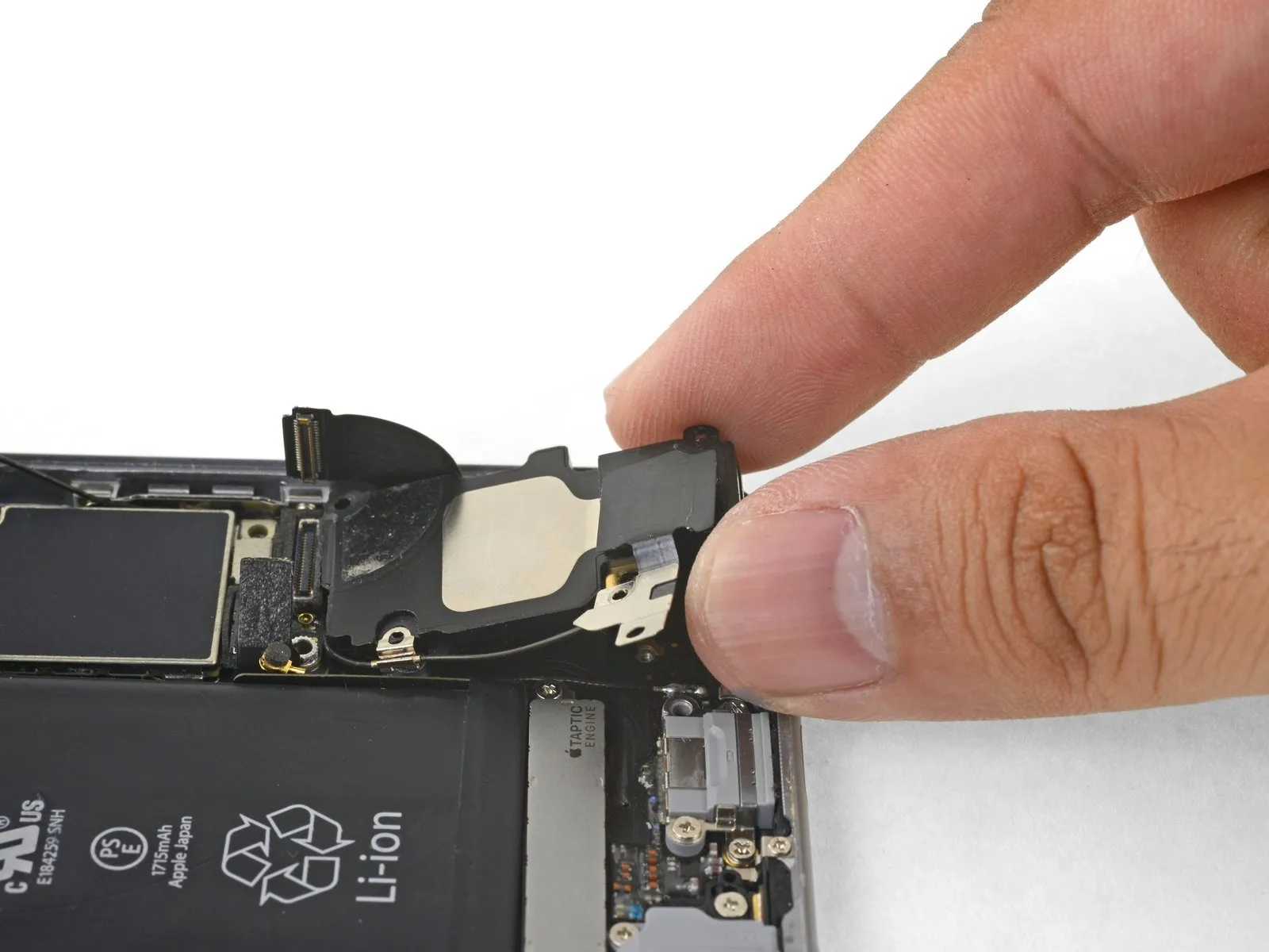
Using a prying tool, carefully separate the speaker module from its housing, avoiding excessive force.
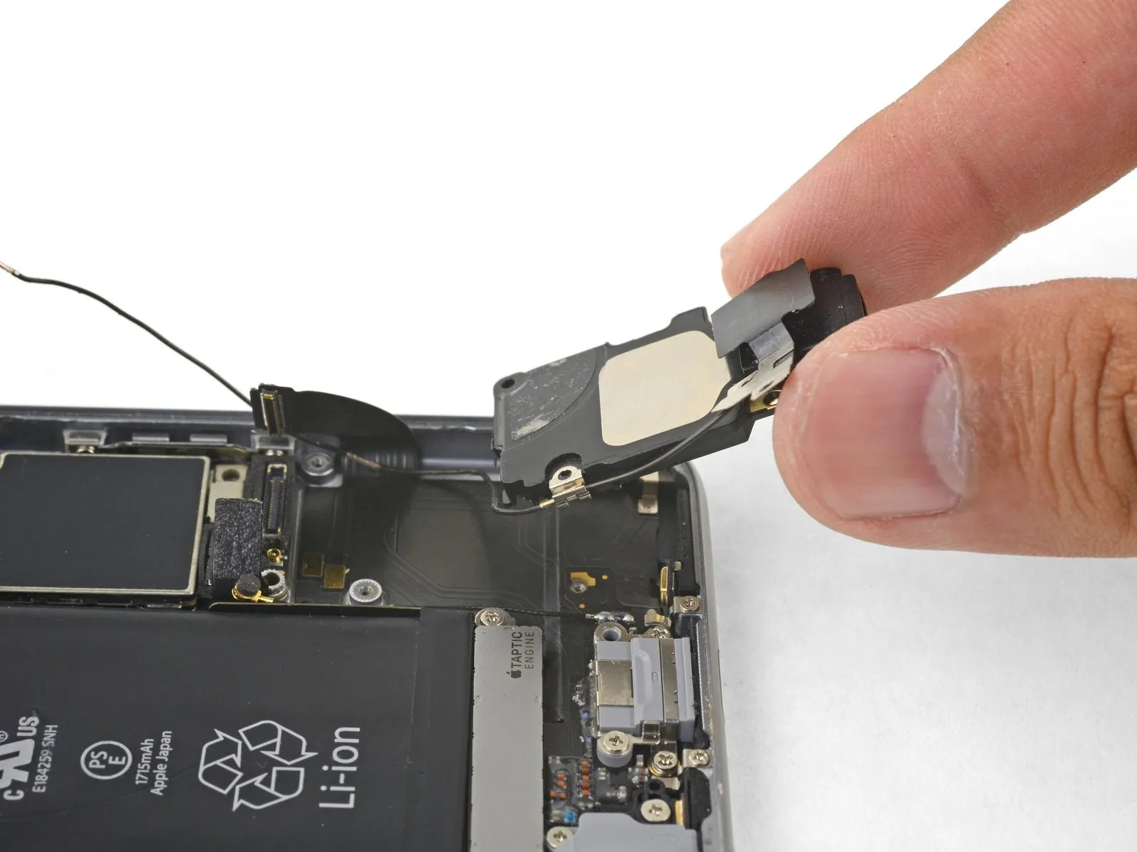
Carefully raise the speaker module, now detached, away from the device to fully extract it.
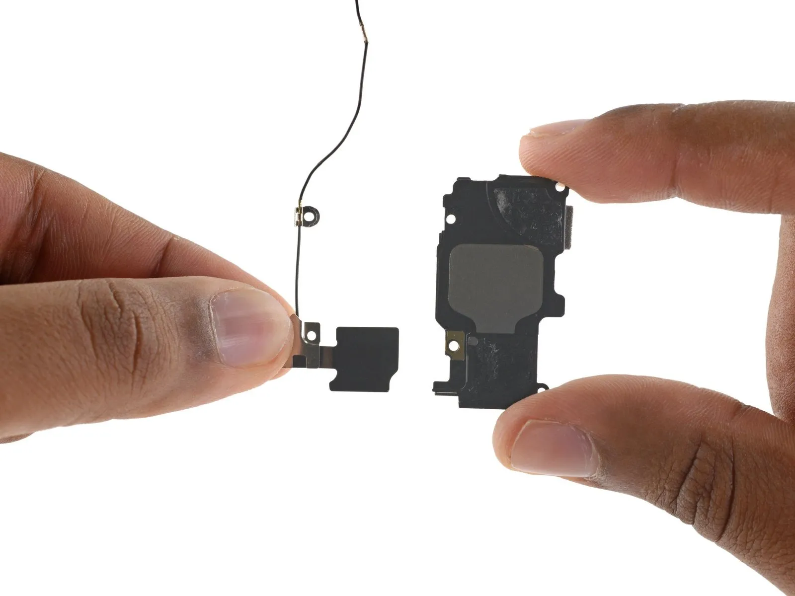
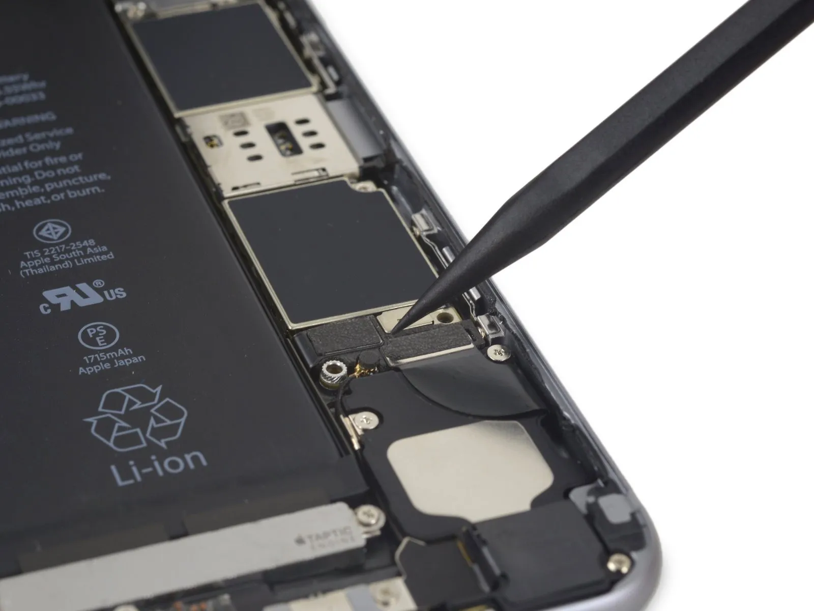
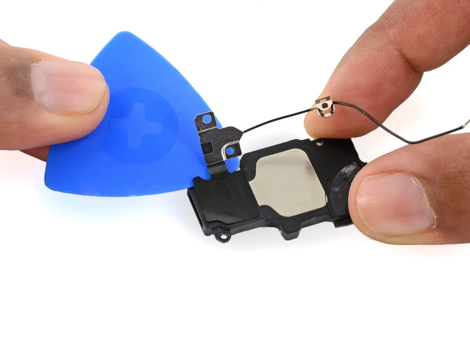
Step 33 | Wi-Fi Diversity Antenna
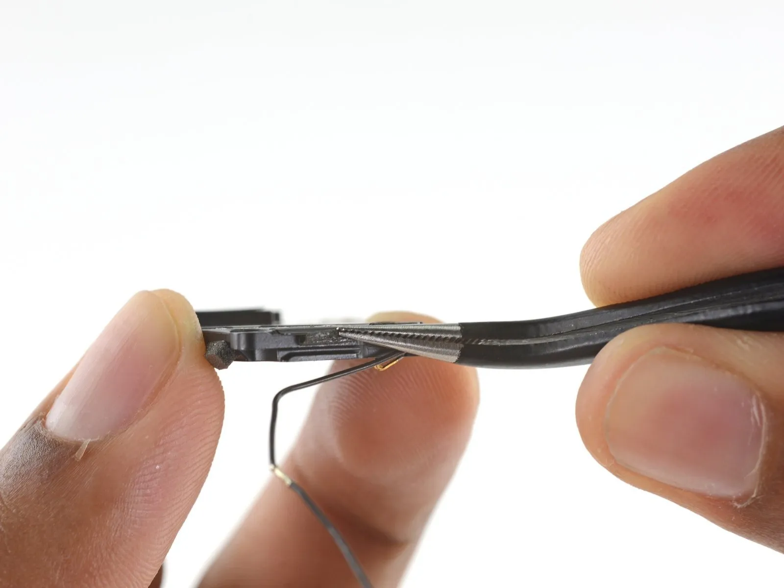
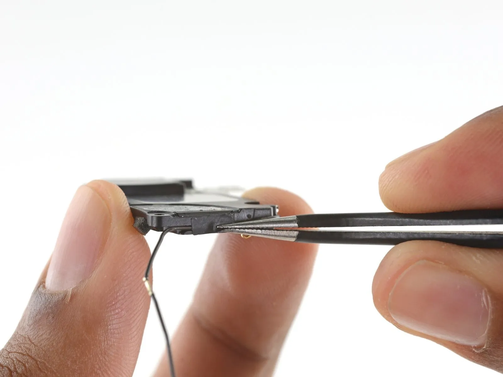
Carefully peel away the adhesive tape securing the antenna cable located along the speaker's perimeter.
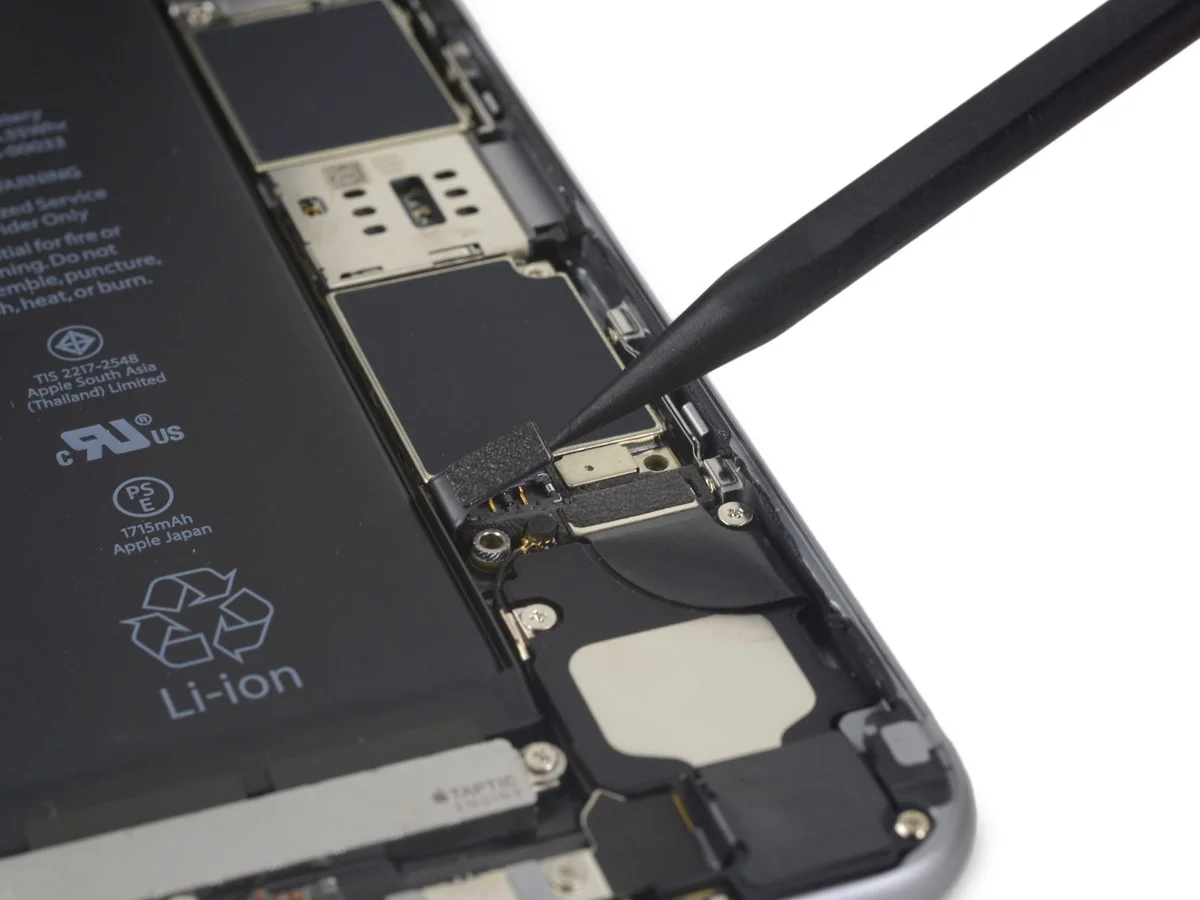
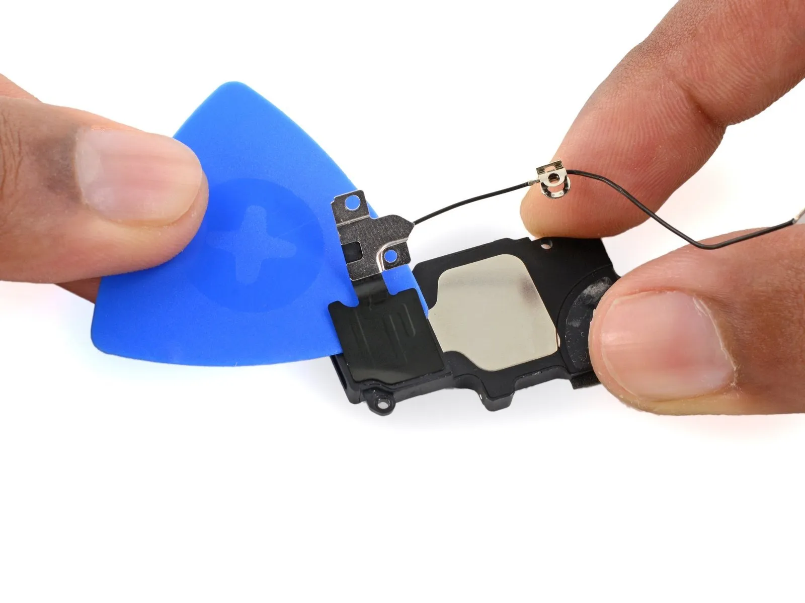
Step 34
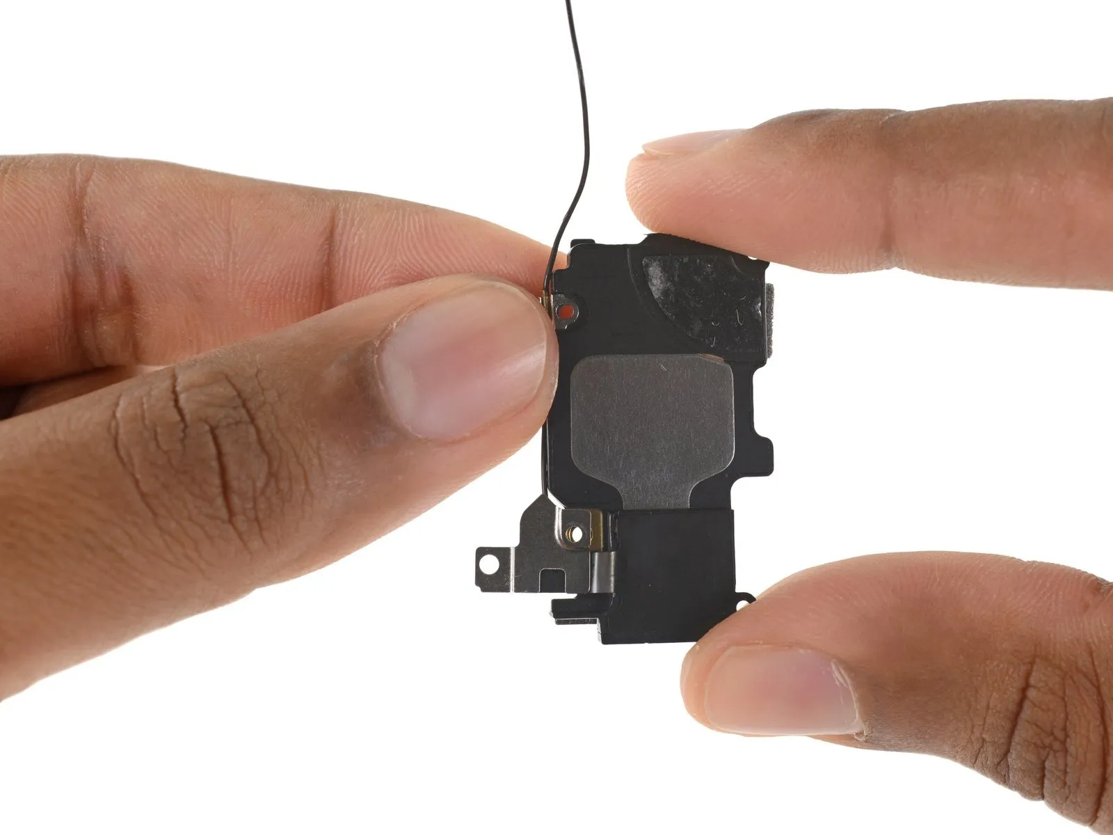
Detach the cable restraint located on the speaker's left-hand side.
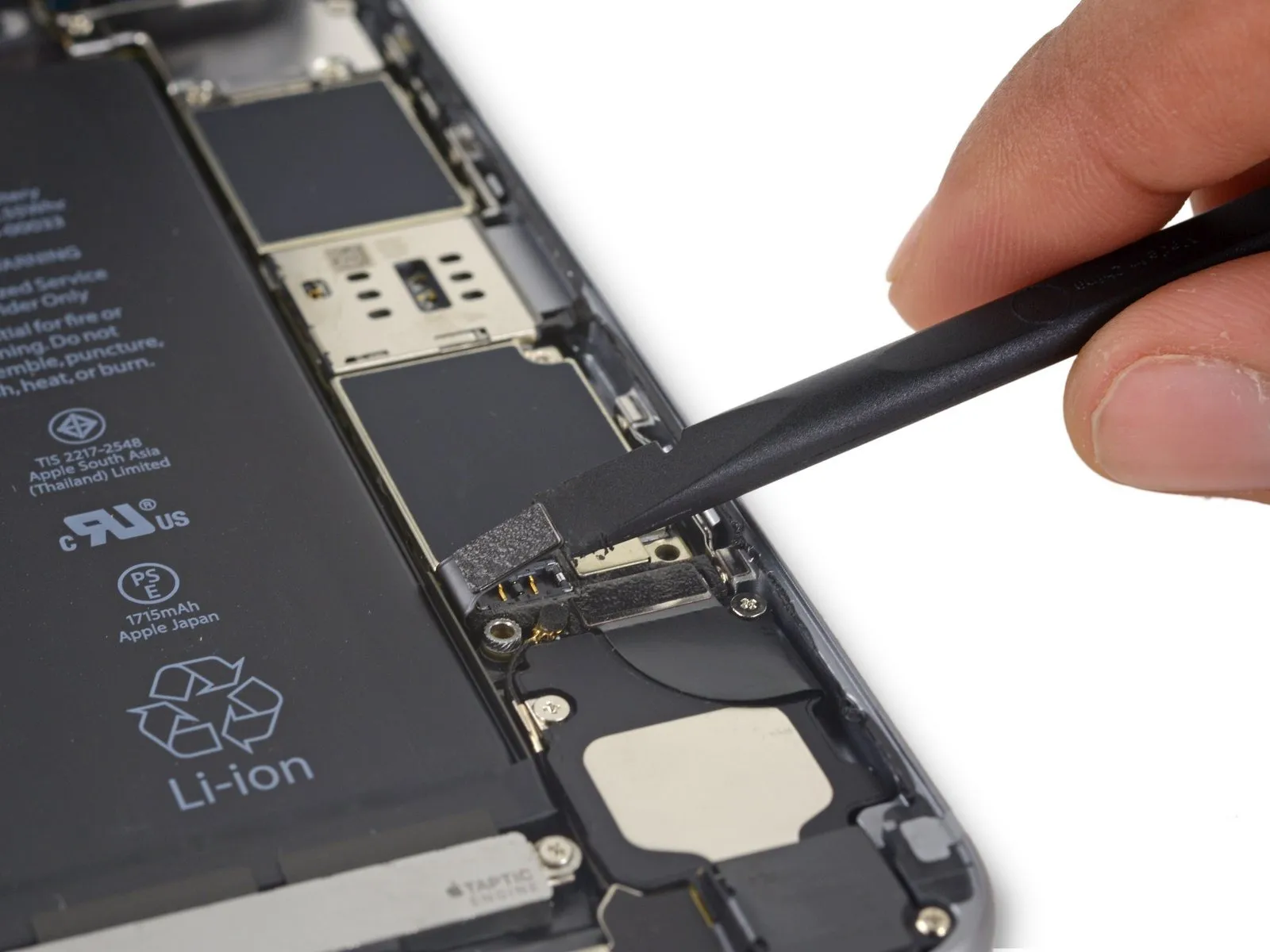
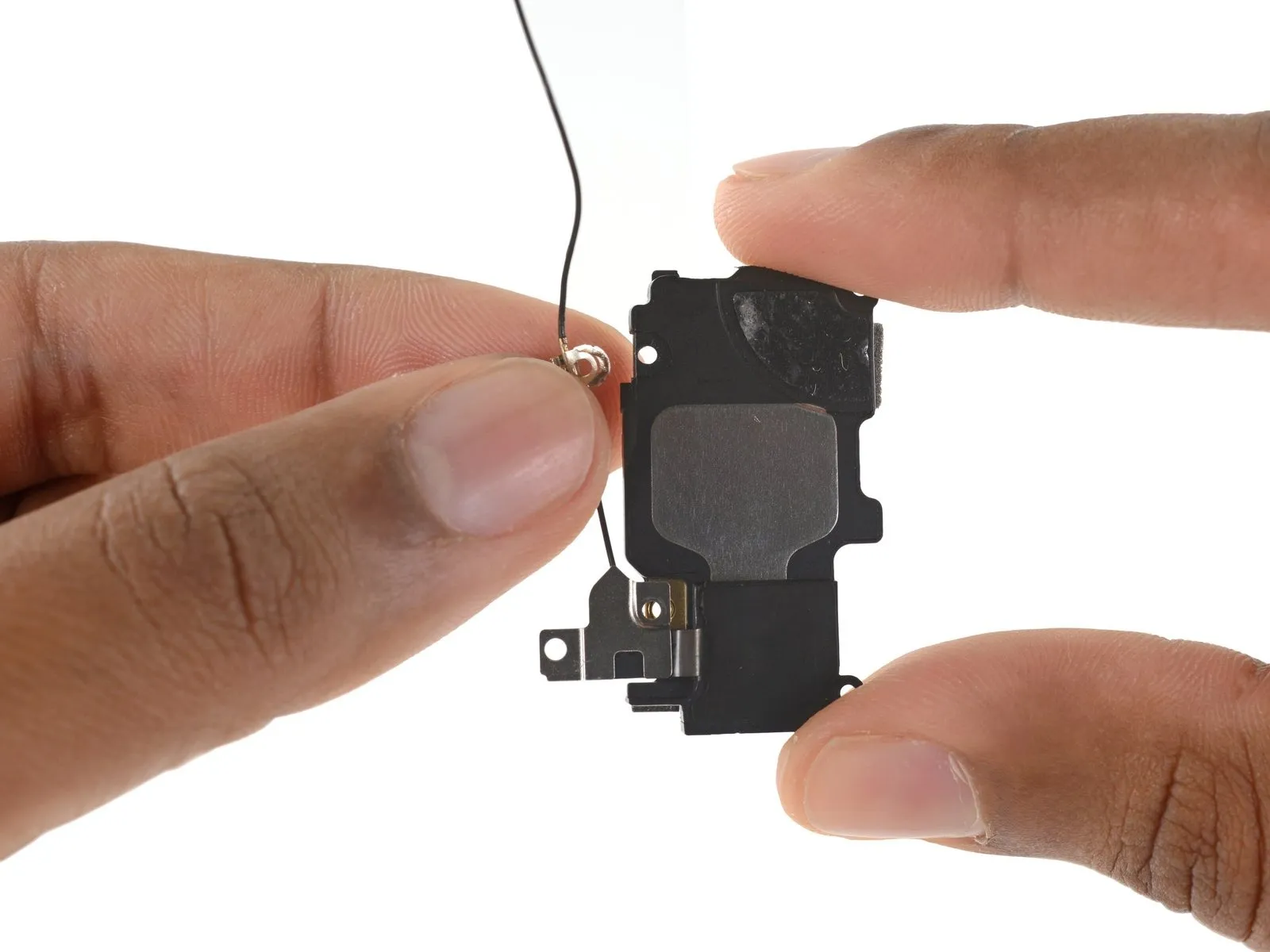
Step 35
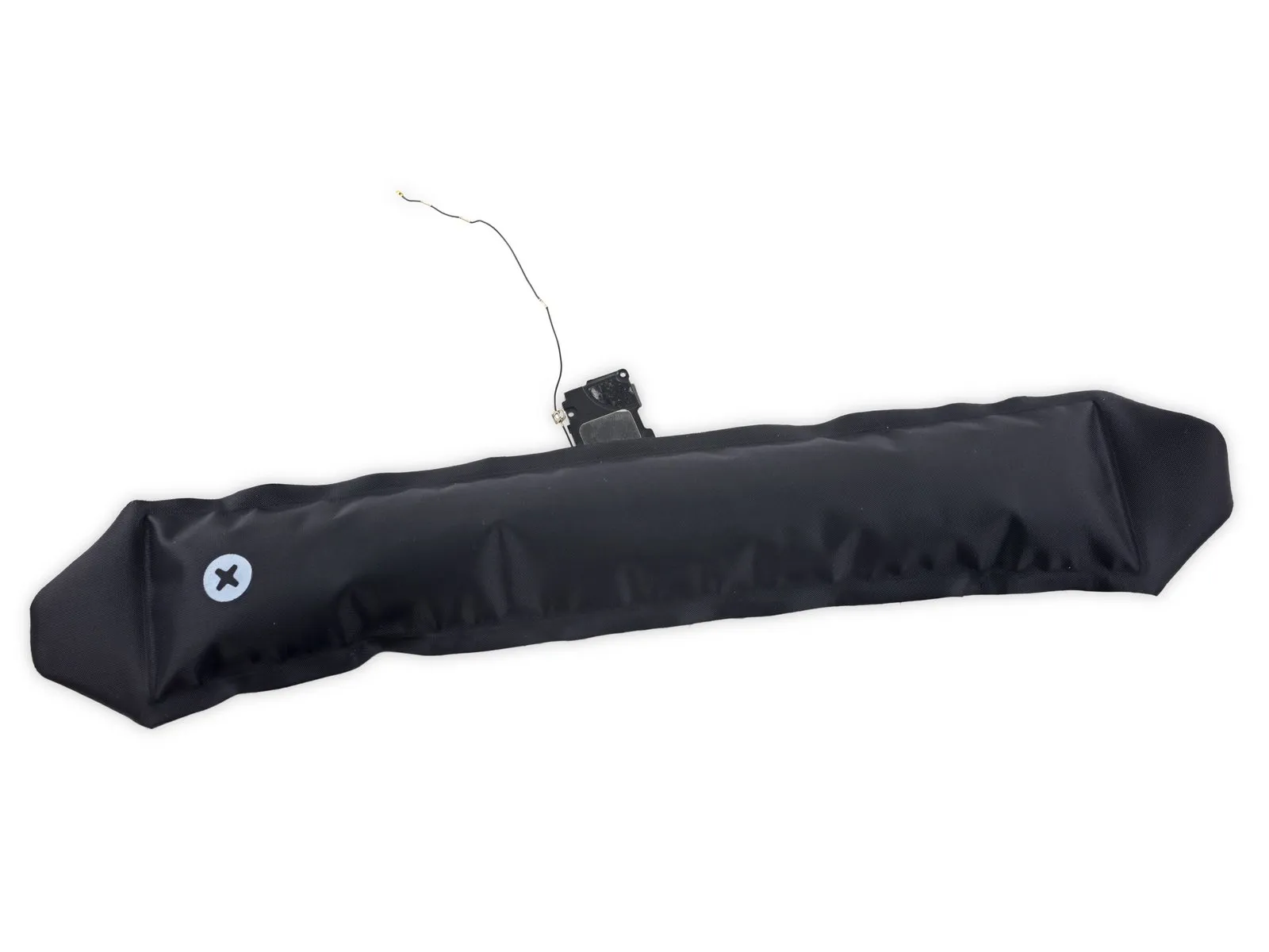
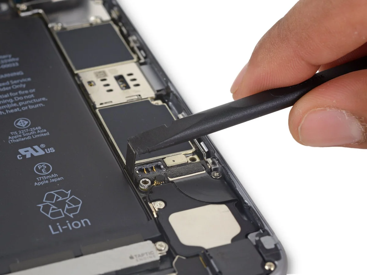
Using an iOpener, apply gentle warmth across the antenna to loosen the adhesive bond holding it in place on the speaker.
Carefully insert a plastic opening pick between the antenna and the speaker to release the adhesive bond.
Step 36