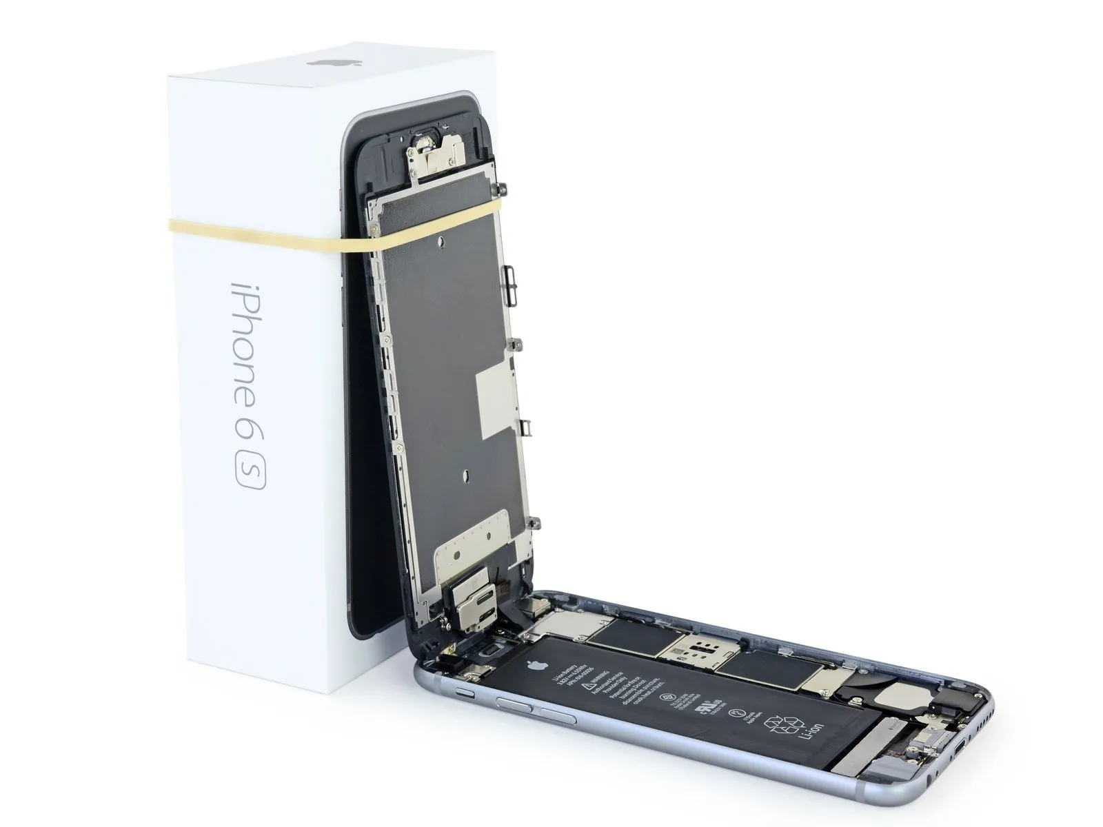
iPhone 6s Logic Board Replacement
Using the instructions provided, perform the necessary actions to substitute theThe main circuit board, containing the integrated circuits and components that control the device's functions, is referred to as the logic board.Within an iPhone 6s.
- Carefully observe that the specified torque of 14 Nm must be applied when tightening the M6 bolt using a 9.5 mm socket and torque wrench to prevent damage.For every iPhone, proceed with the following steps.The main circuit board, containing the integrated circuits and other electronic components, is referred to as the logic board.The factory-linked Touch ID fingerprint sensor requires replacement with a new, pre-paired unit.The main circuit board, containing the integrated circuits and electronic components, is referred to as the logic board.Failure to also install a correctly paired replacement home button will render Touch ID functionality inoperable.The main circuit board, containing integrated circuits and other electronic components, is referred to as the logic board..
- This document serves as a resource for replacing theApply the adhesive-backed electromagnetic interference (EMI) shielding stickers to the logic board..
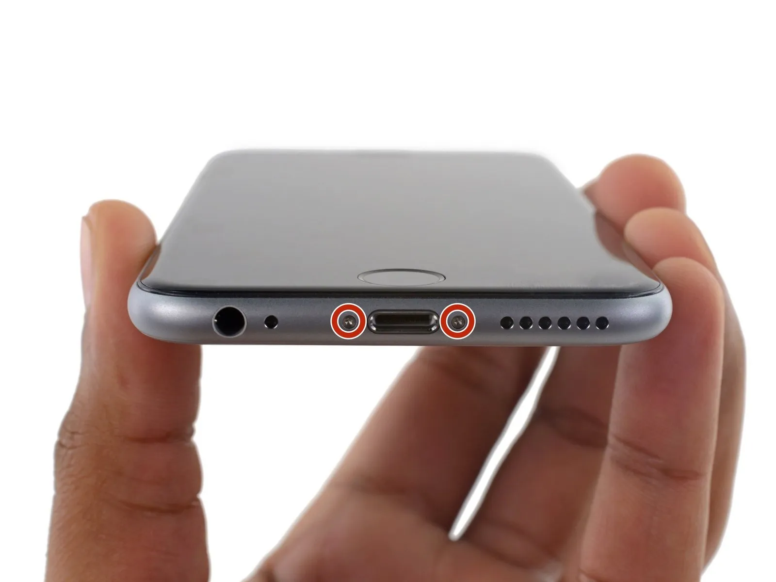
Step 1 | Pentalobe Screws
- Using a wrench, securely tighten the bolt to a torque of 45 Nm, ensuring the clamp remains firmly fixed to the housing.Using the specified tools, carefully perform the procedure, adhering to all safety precautions and noting any dimensions or values provided.
- To prevent a potential fire or explosion hazard from the lithium-ion battery during disassembly, ensure its charge level is reduced to less than 25% beforehand; a fully charged battery poses a risk of ignition if damaged.
- To prevent electrical shock or damage to components, ensure the iPhone is completely de-energized prior to starting the repair process.
- Detach the pair ofUse a screwdriver with a 3.4 mm P2 Pentalobe bit to loosen the screws.Located along the iPhone's lower edge, flanking the Lightning connector, you'll find them.
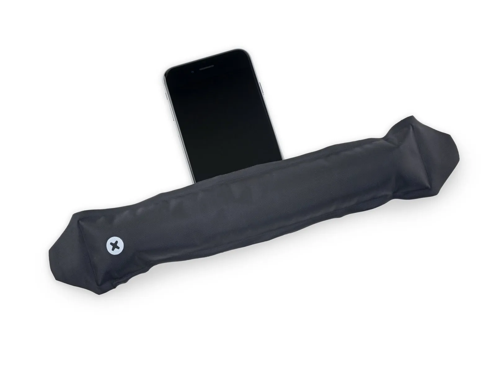
Step 2 | Anti-Clamp instructions


- Ensure the clamping force is precisely 1.5 Newtons when securing the 3mm diameter shaft to prevent damage.Using the specified tools, carefully measure and observe all safety precautions while working.
- To simplify the opening process, the following two steps utilize the Anti-Clamp tool, a custom design; if you do not have this tool, proceed to the steps three sections later for an alternative approach.
- Refer to the accompanying guide for detailed procedures regarding Anti-Clamp operation.
- To release the Anti-Clamp's arms, move the blue handle in a rearward direction.
- Position the arms so they extend across the iPhone's left or right side.
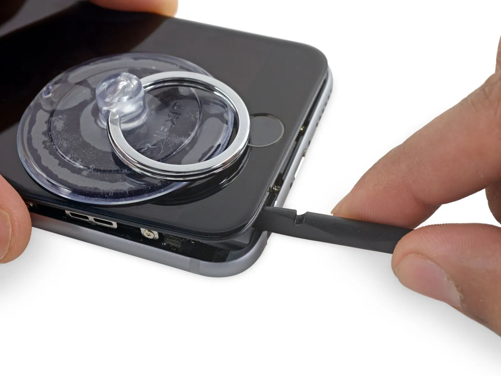
- Affix two suction cups, one to the front and one to the rear surface of the iPhone, close to the lower edge, situated directly above the home button.
- Apply vacuum by pressing the cups firmly against the surface needing treatment.
- To improve the Anti-Clamp's grip if the iPhone's exterior feels excessively smooth, apply adhesive tape to the device's surface.
Step 3


- Securely clamp the workpiece, ensuring it is positioned precisely within the 1/8-inch tolerance using appropriate fixtures and tools, and always wear safety glasses to protect against potential flying debris.Using the specified tools, carefully perform the procedure while strictly adhering to all safety precautions and maintaining awareness of the indicated dimensions and numerical values.
- To secure the arms, advance the blue handle in the direction indicated.
- Rotate the handle fully, completing a 360-degree turn, observing for the point when the cups begin to expand.
- Maintain proper positioning of the suction cups; should misalignment occur, gently release the suction and reposition the arms.
- Once sufficient separation is achieved by the Anti-Clamp tool, slide a prying tool beneath the display panel.
- To ensure adequate clearance, adjust the handle position by 90 degrees.
- Allow several seconds to elapse and avoid rotating the component beyond a 90-degree movement in any single increment; the Anti-Clamp feature and settling time will facilitate proper adjustment.
Step 4 | Opening Procedure
- Carefully clamp the component using a vise with a maximum pressure of 50 psi, ensuring the 1/8-inch diameter hole remains unobstructed, and observe the warning regarding potential damage to the housing.Using the specified tools, carefully perform the procedure while strictly adhering to all safety precautions and ensuring all dimensions and numerical values are precisely maintained.
- Lacking an Anti-Clamp tool, proceed with the subsequent three steps to utilize a suction handle.
- Using a hair dryer or iOpener, gently warm the bottom edge of the iPhone's casing with moderate heat for approximately 60 seconds.
- Applying heat will loosen the adhesive bonds holding the display in place, facilitating separation.
Step 5
- To access the 6s display, carefully release the adhesive strip that runs along its edges; replacement adhesive strips should be prepared beforehand if desired, as the repair can be performed without them and without affecting device operation.
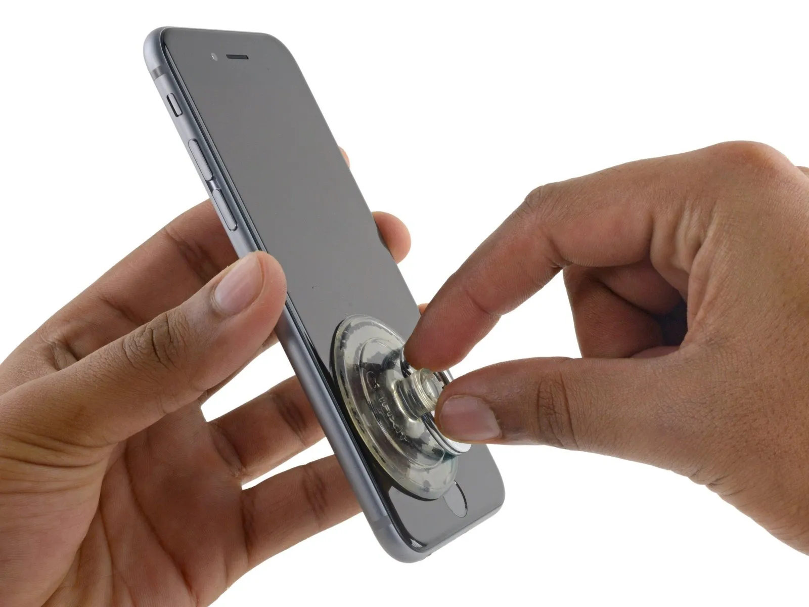
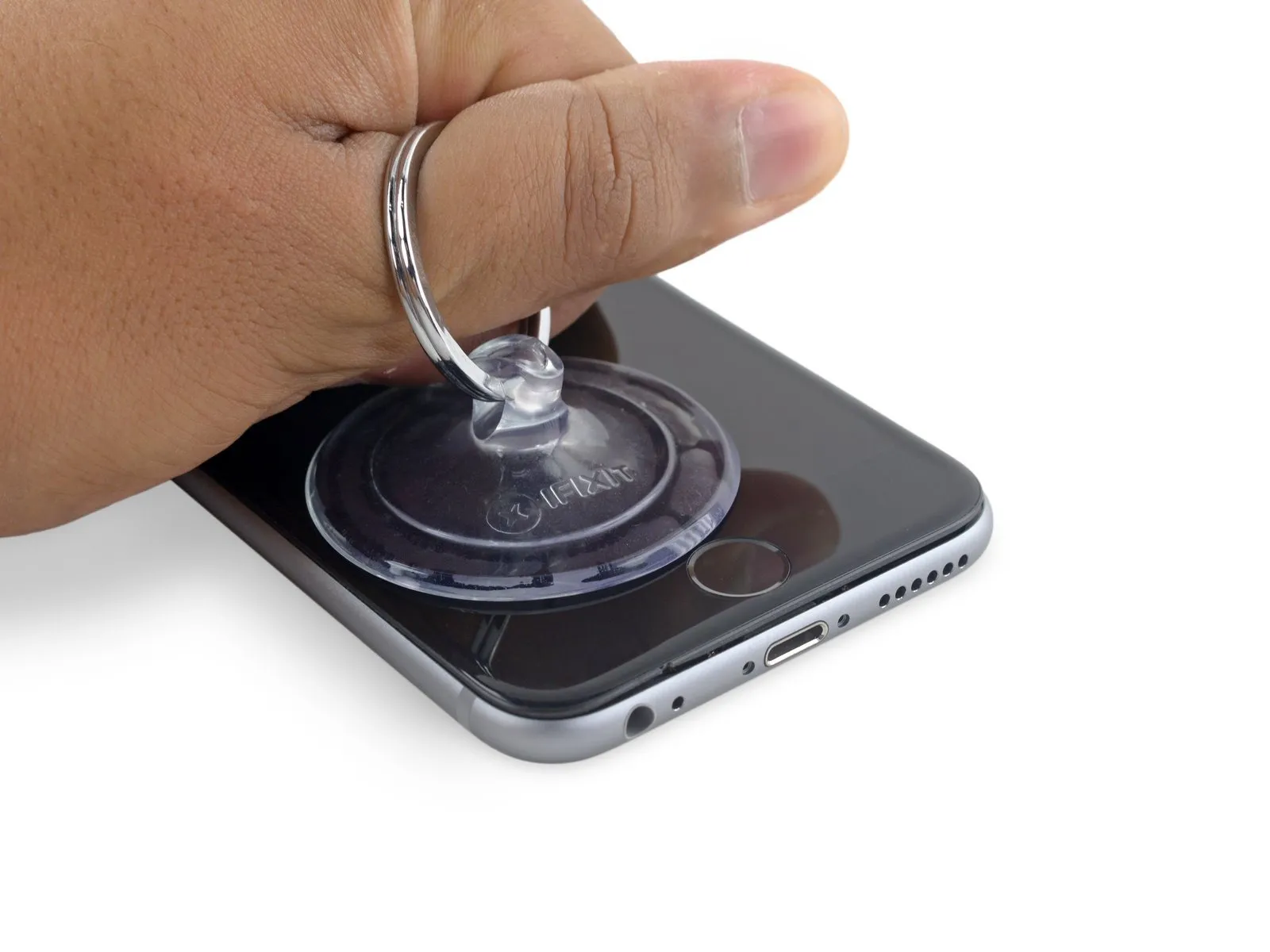
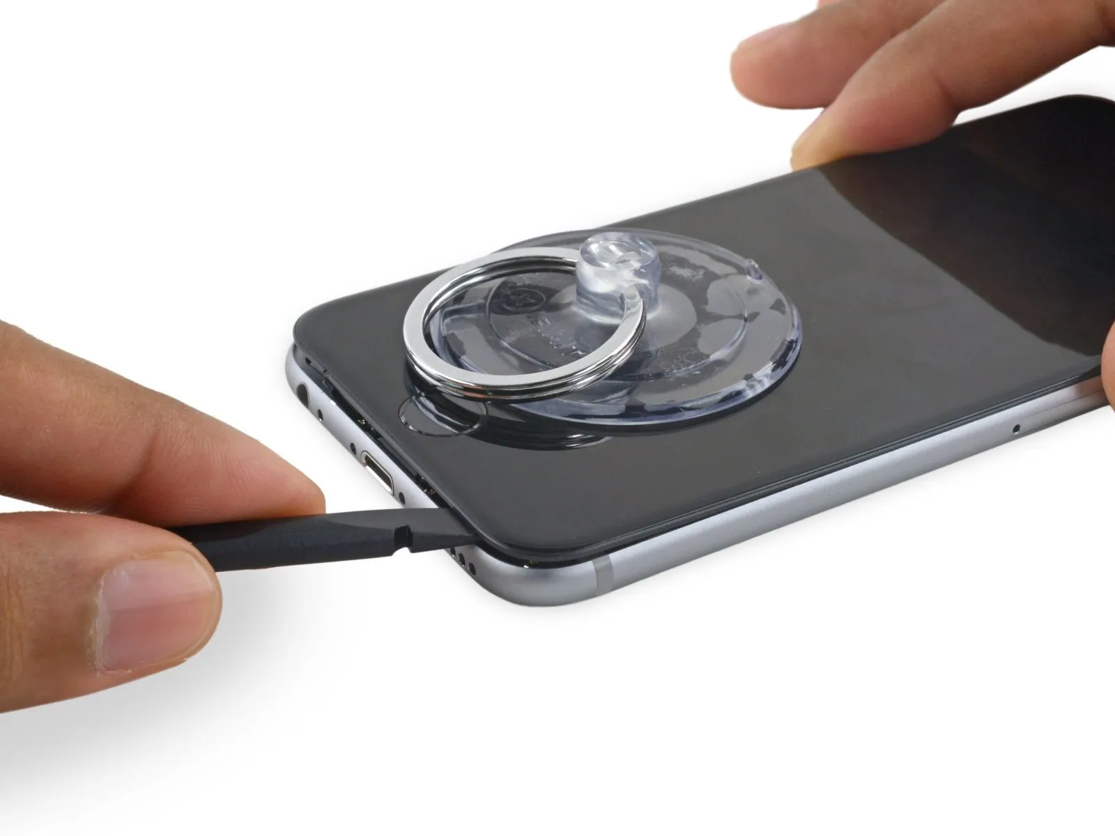
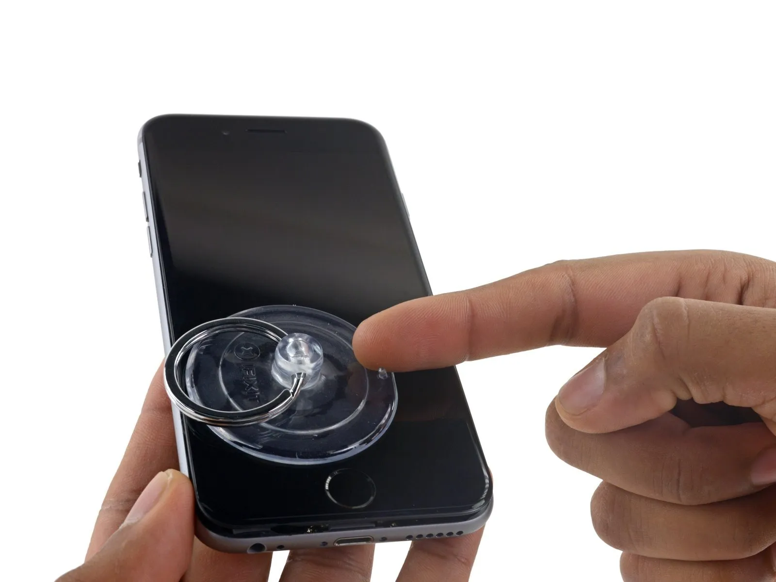
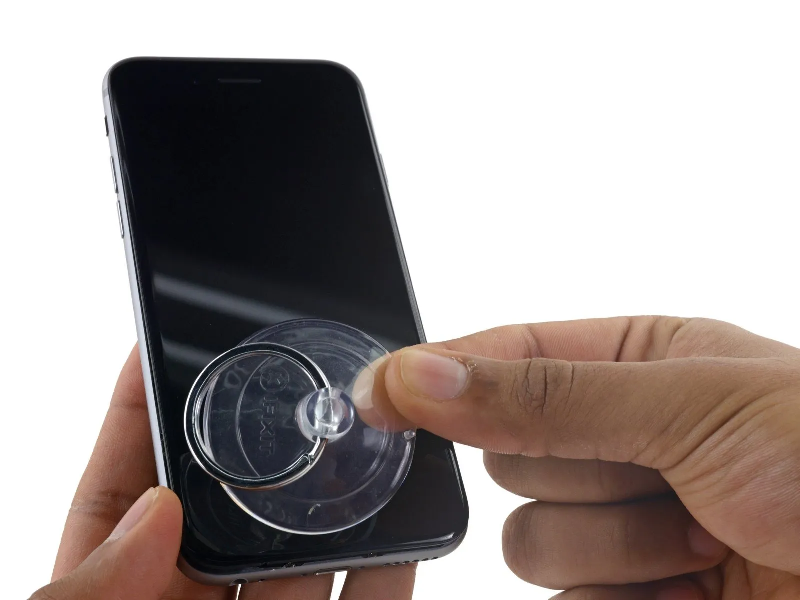
- Securely attach a suction cup to the display assembly's lower-left corner.
- Avoid positioning the suction cup directly on the home button.
- To facilitate suction cup attachment on a severely cracked display, apply a layer of clear packing tape across the damage; as an alternative, a robust adhesive tape can be substituted for the suction cup. Should these methods prove ineffective, superglue can be used to secure the suction cup directly to the fractured screen.
Step 6
Using a 5/32-inch hex key, carefully tighten the four mounting screws securing the fan assembly to the motor housing, ensuring each is snug but not over-tightened to prevent damage; observe a torque of 6 in-lbs per screw.
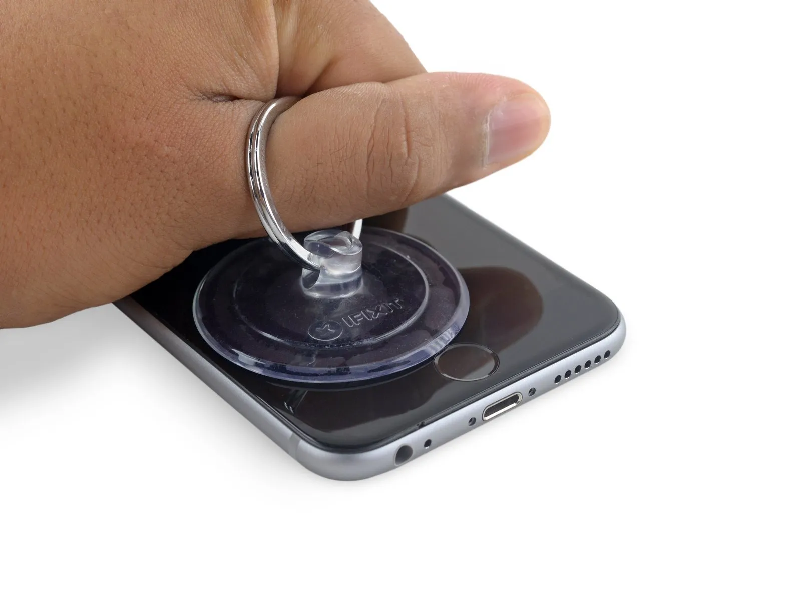
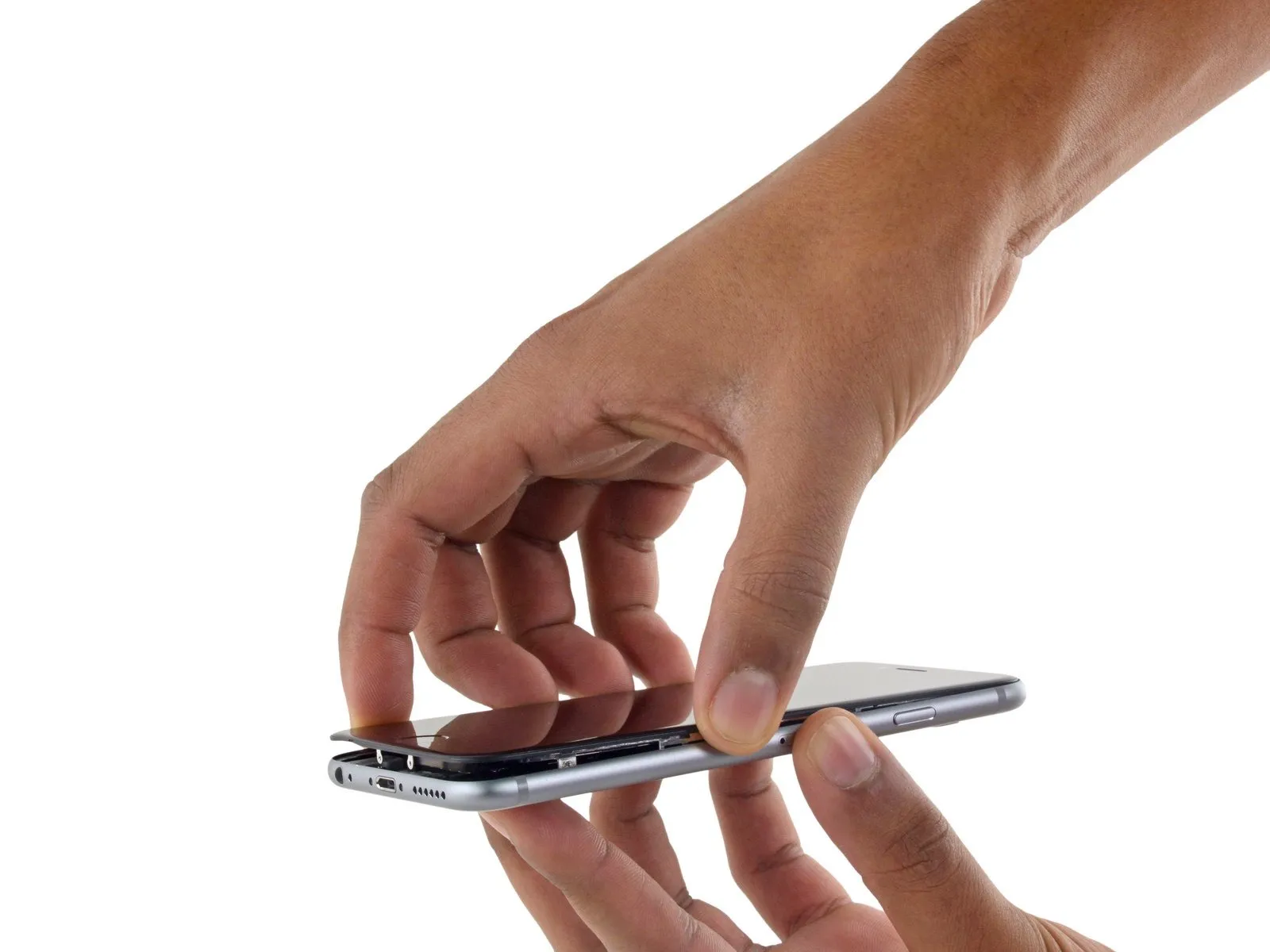
- Apply steady, even force to lift the suction cup, generating a small separation between the front panel and the rear case.
- Exercise caution and use steady, even pressure when installing the display assembly, as it requires a snug fit and is secured with adhesive.
- To avoid display assembly damage, use minimal force when separating it from the rear case; the goal is to establish a narrow separation.
- To ease separation of the display from the chassis, apply warmth to the front surface of the iPhone with an iOpener, hair dryer, or heat gun until the area reaches a temperature that is uncomfortably warm to the touch. This process loosens the adhesive that holds the display’s perimeter in place.
Step 7
Using a 5/32-inch hex key, carefully tighten the four M4x8 pan head screws securing the fan assembly to the heatsink, ensuring a torque of 4.5 in-lbs to prevent damage.
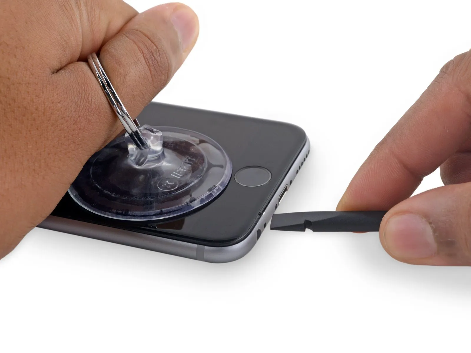
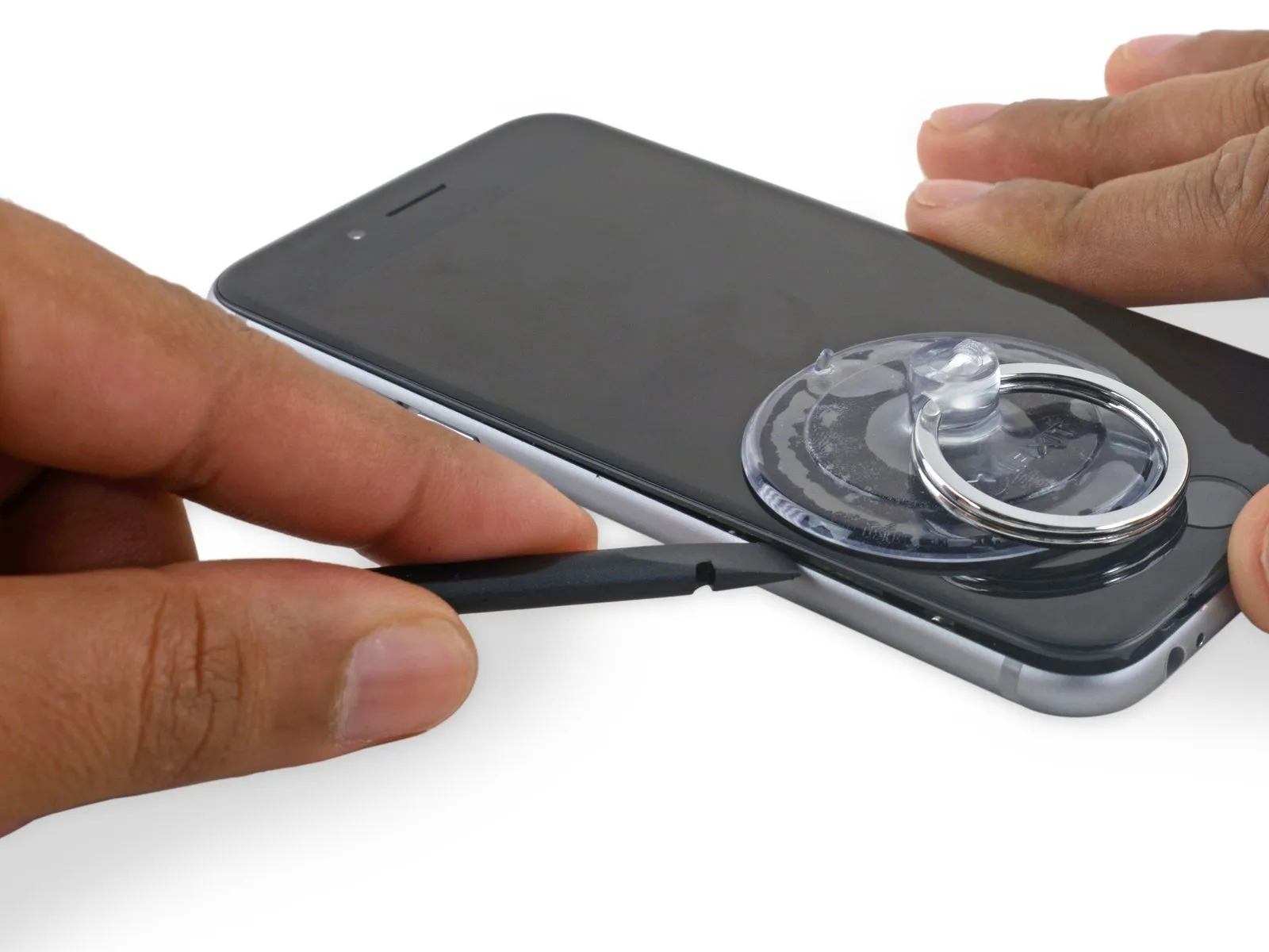
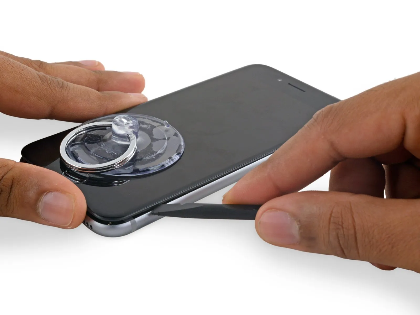
- To initiate separation of the device housing, insert a prying tool into the indentation located on the bottom surface of the display, positioned directly above the headphone jack; this area minimizes the risk of damage.
- Using a spudger, insert its flat end into the separation between the display and the back cover, positioning it immediately over the headphone jack.
Step 8
Using a 5/32-inch hex key, carefully tighten the four M4x8 pan head screws securing the fan assembly to the heatsink, ensuring a torque of no more than 6 in-lbs to prevent damage.
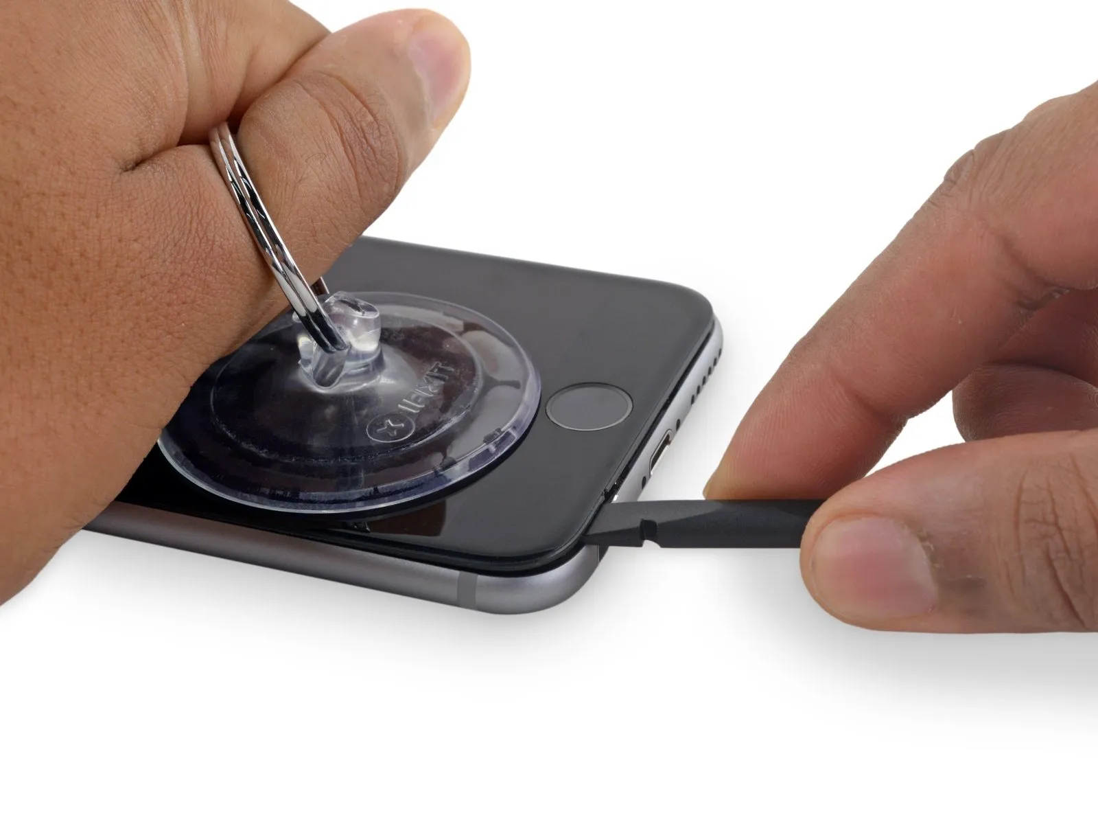
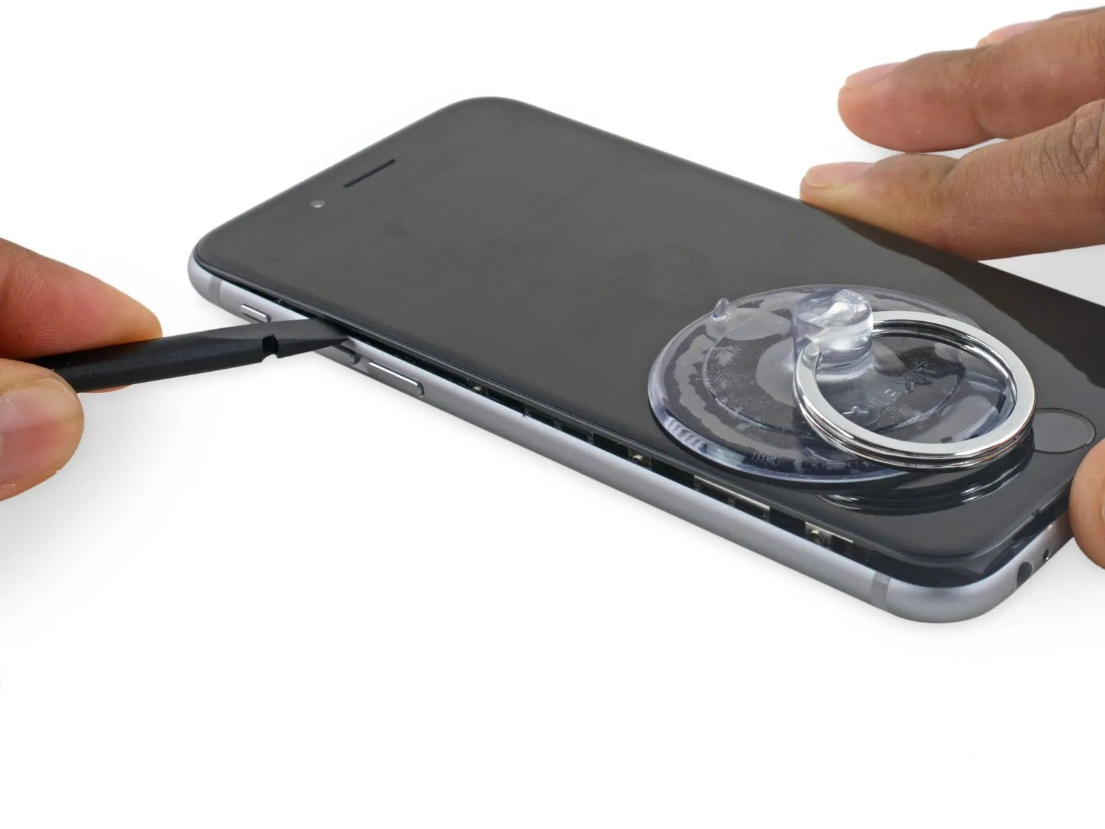
- Using a spudger, gently increase the separation between the front panel assembly and the phone's main body.
Step 9
Using the 5/32-inch hex key, carefully tighten the three retaining screws on the motor assembly to a torque of 3.5 Nm, ensuring that you observe the safety warning regarding eye protection.
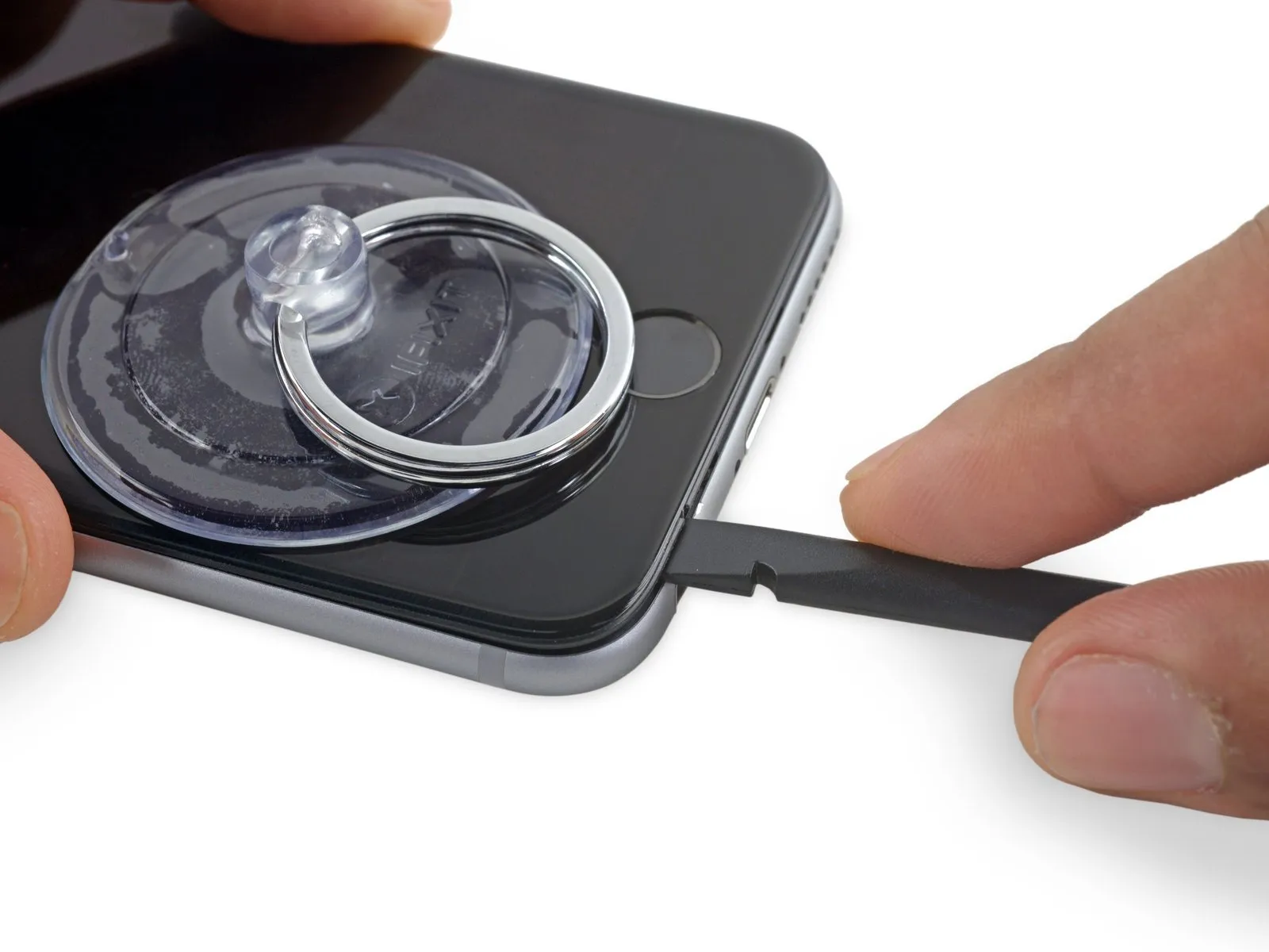
- Using the tool's straight edge, carefully slide it into the designated space.Use a plastic pry tool, often referred to as a spudger.Locate this component on the device's left-hand side, specifically positioned in the space separating the display assembly and the rear case.
- Carefully move theUse a plastic pry tool, often referred to as a spudger.Carefully lift the device's side to release the adhesive and disengage the retaining clips.
Step 10
Using a 5/32-inch hex key, carefully tighten the three retaining screws securing the fan motor to the blower housing, ensuring each is snug but not over-tightened to prevent damage; observe a torque of 6 in-lbs per screw.
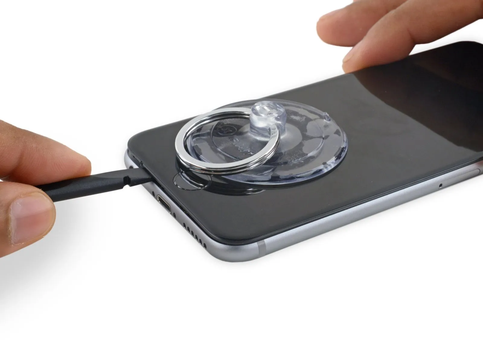
- Carefully detach theUse a plastic pry tool, often referred to as a spudger.Carefully position the component back into its original location along the lower edge of the device, ensuring it aligns with the point where separation occurred.
- Carefully move theUse a plastic pry tool, often referred to as a spudger.Locate the edge of the device's base, then proceed along that side towards the right.
Step 11
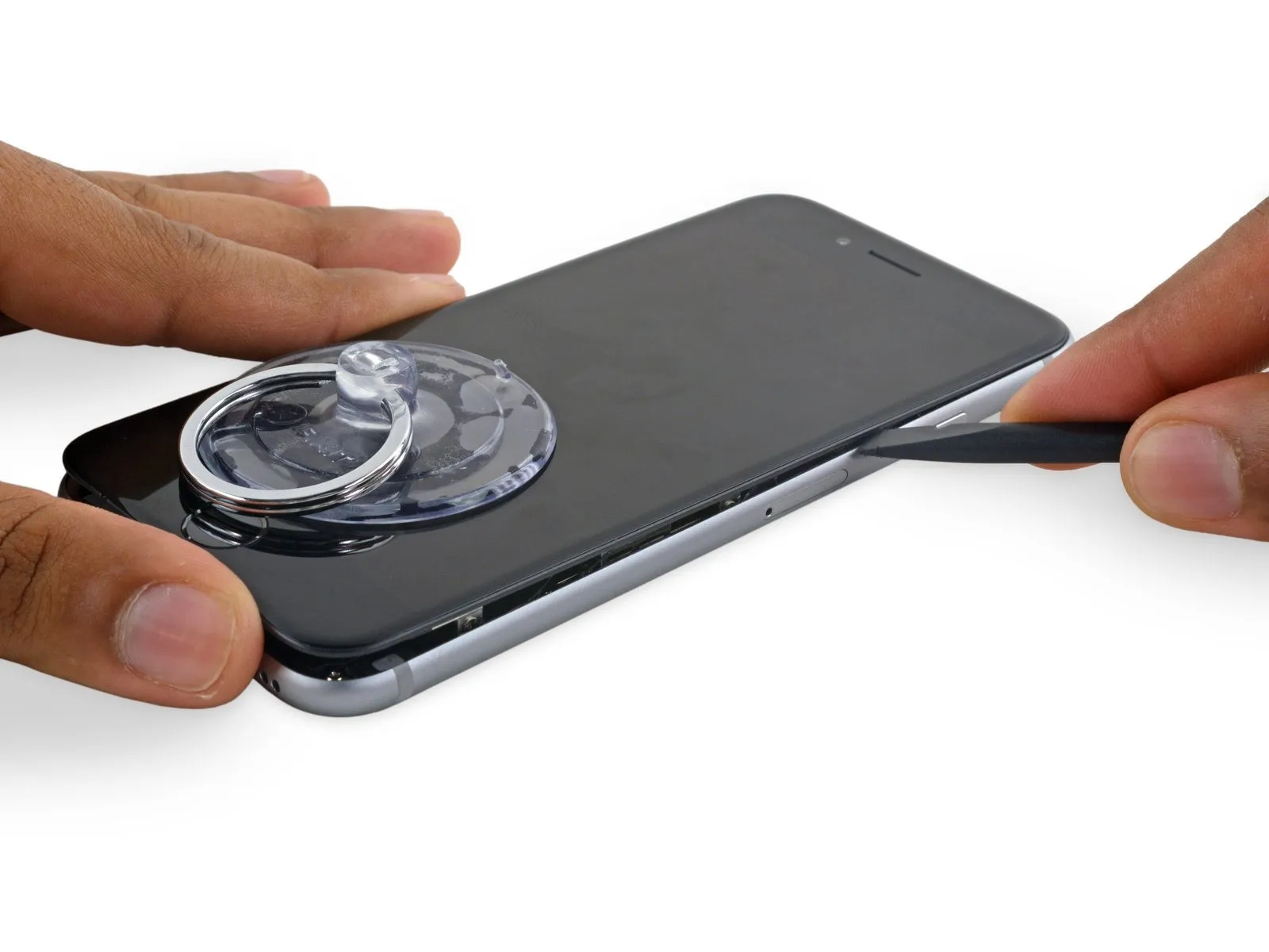
- Carefully move theUse a plastic pry tool to gently separate.Proceed along the right edge, carefully releasing the adhesive bond and disengaging the display clips from their securing points on the iPhone.
Step 12

- Employ the 3/8-inch socket wrench to securely tighten the retaining bolt to a torque of 15 Nm, ensuring the correct alignment of the actuator arm and observing caution to prevent damage to the housing.Employ a vacuum-creating device to secure the component.Carefully separate the display assembly from the device housing by releasing the remaining adhesive bond.
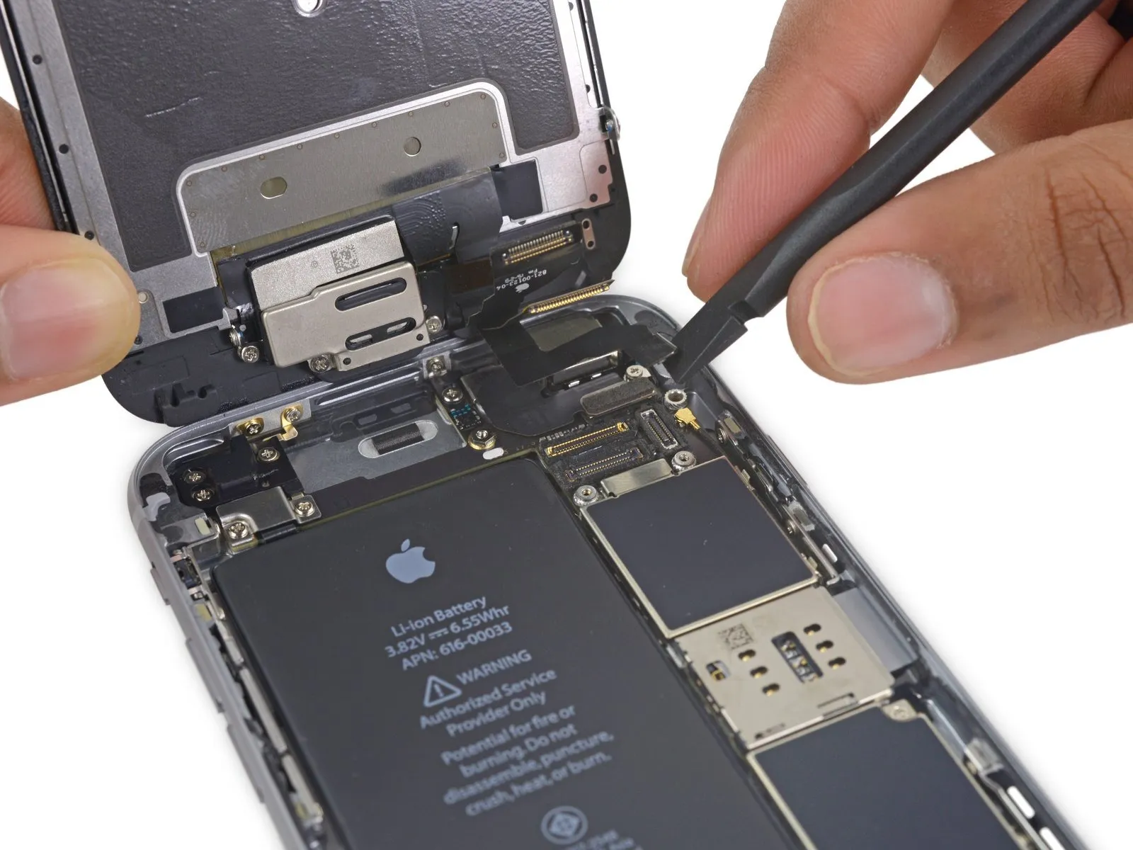
- To prevent damage, limit the display's opening angle to a maximum of 90 degrees; three cables remain connected at the top edge and are susceptible to breakage if pulled taut.
Step 13
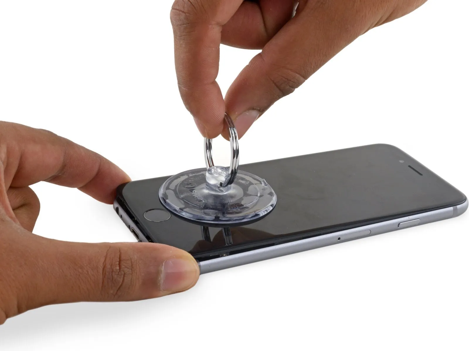
To detach the suction cup, grasp the small projection located on its upper surface and lift, separating it from the front panel.
Step 14
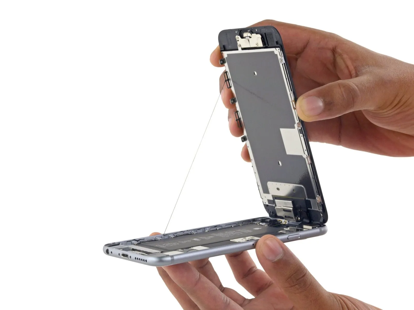
- Carefully raise the display assembly, leveraging the front panel's top clips to act as a hinge and separate the device.
- Carefully position the display at a roughly 90-degree angle, then secure it in an upright position using a support to prevent movement during the repair process.
- To avoid stressing the display's wiring during the repair process, secure it with a rubber band.
- As a temporary measure, an unopened, sealed can of soda can substitute for the display during the repair process.
- If you intend to substitute fresh adhesive along the display's perimeter during reassembly, stop at this point.
- To ensure proper alignment during reassembly, guide the camera-side edge of the screen body beneath the main body's perimeter; then, position the screen frame's hooks beneath the main body's rim and gently push them towards the camera end, facilitating cover closure and secure clipping.
- Ensure these clasps, which function as a substitute for a hinge, are positioned correctly beneath the phone's outer rim to allow the screen to smoothly and gently return to its closed position, achieving a secure snap.
- To reinstall the screen, begin by applying pressure to secure the upper-right corner, working downwards along the edge, followed by the upper-left corner.
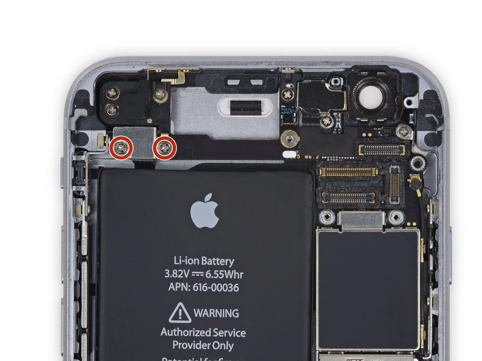
Step 15 | Battery Connector
- Using a Phillips screwdriver, detach the two screws—each measuring the same length—that hold the battery connector bracket in place.
Utilize a 2.9 mm screw for installation.
Utilize a 2.2-millimeter screw.
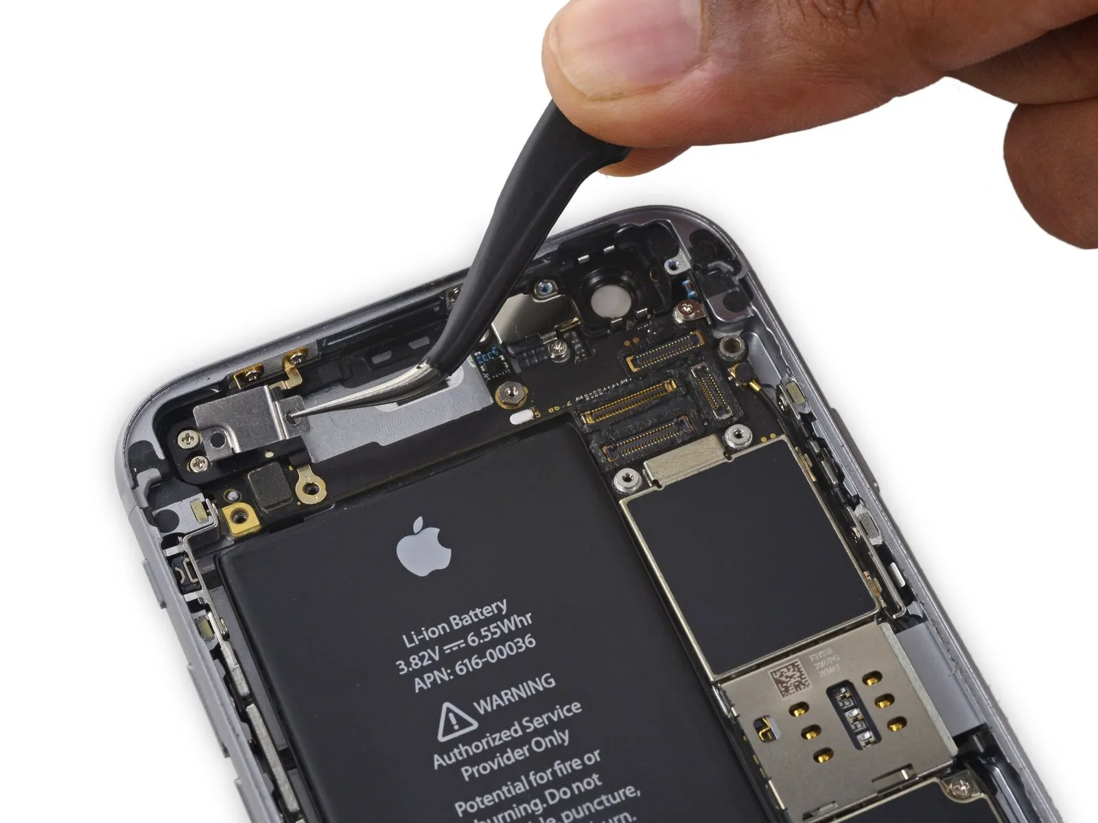
Step 16
Using a 5mm hex screwdriver, detach the bracket securing the battery connector.
Step 17

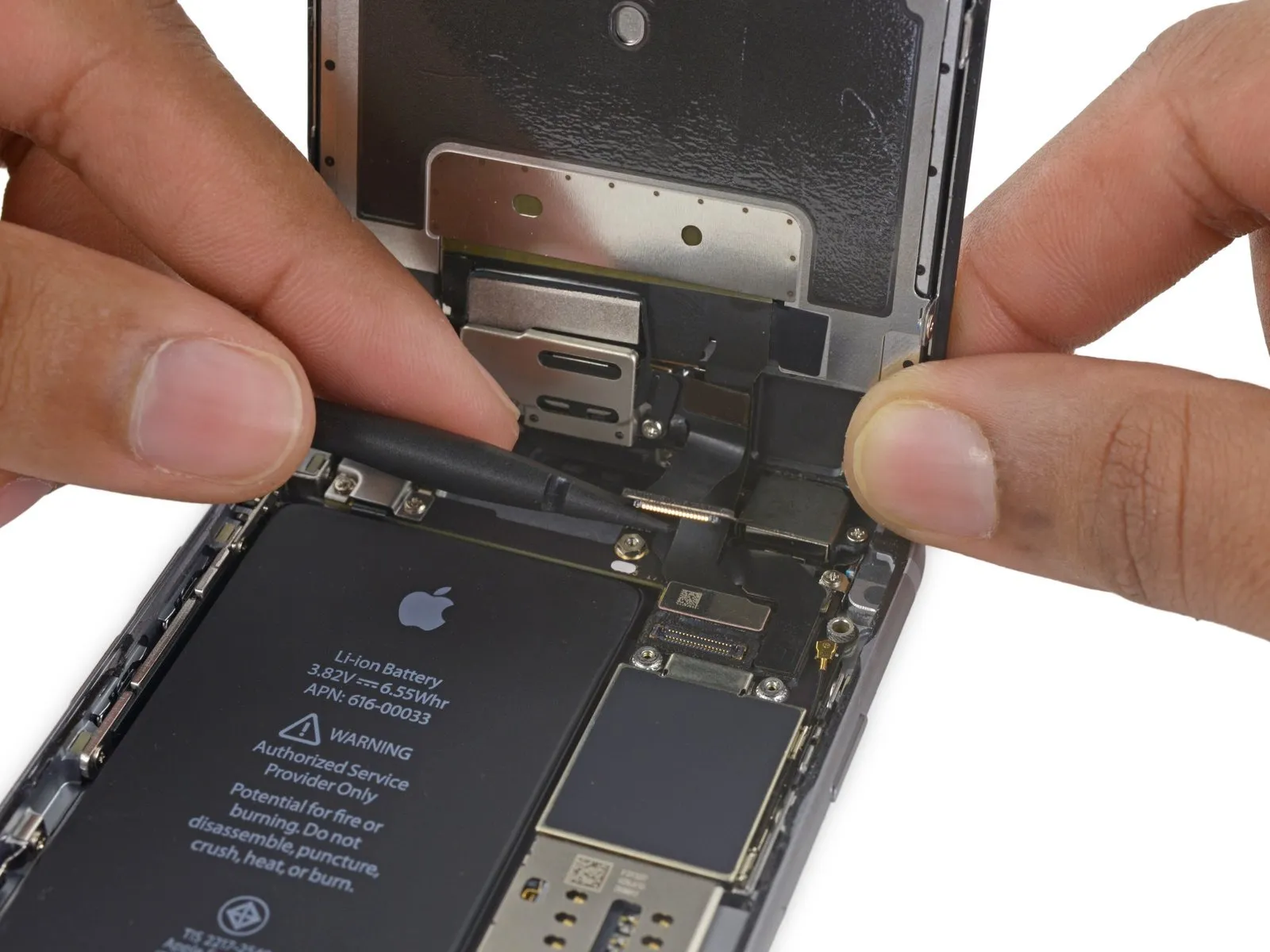
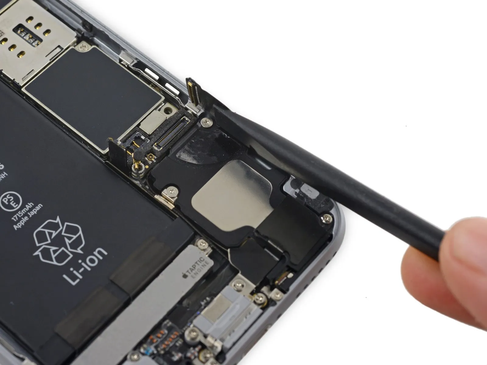
Carefully insert the tip of a screwdriver to.Use a spudger.Using a suitable tool, carefully lift the battery connector vertically away from the logic board.
Step 18
To prevent unintended power-ups during the repair process, carefully disengage the battery connector from its socket on the logic board, ensuring it remains disconnected.
Step 19 | Unfasten the display cable bracket
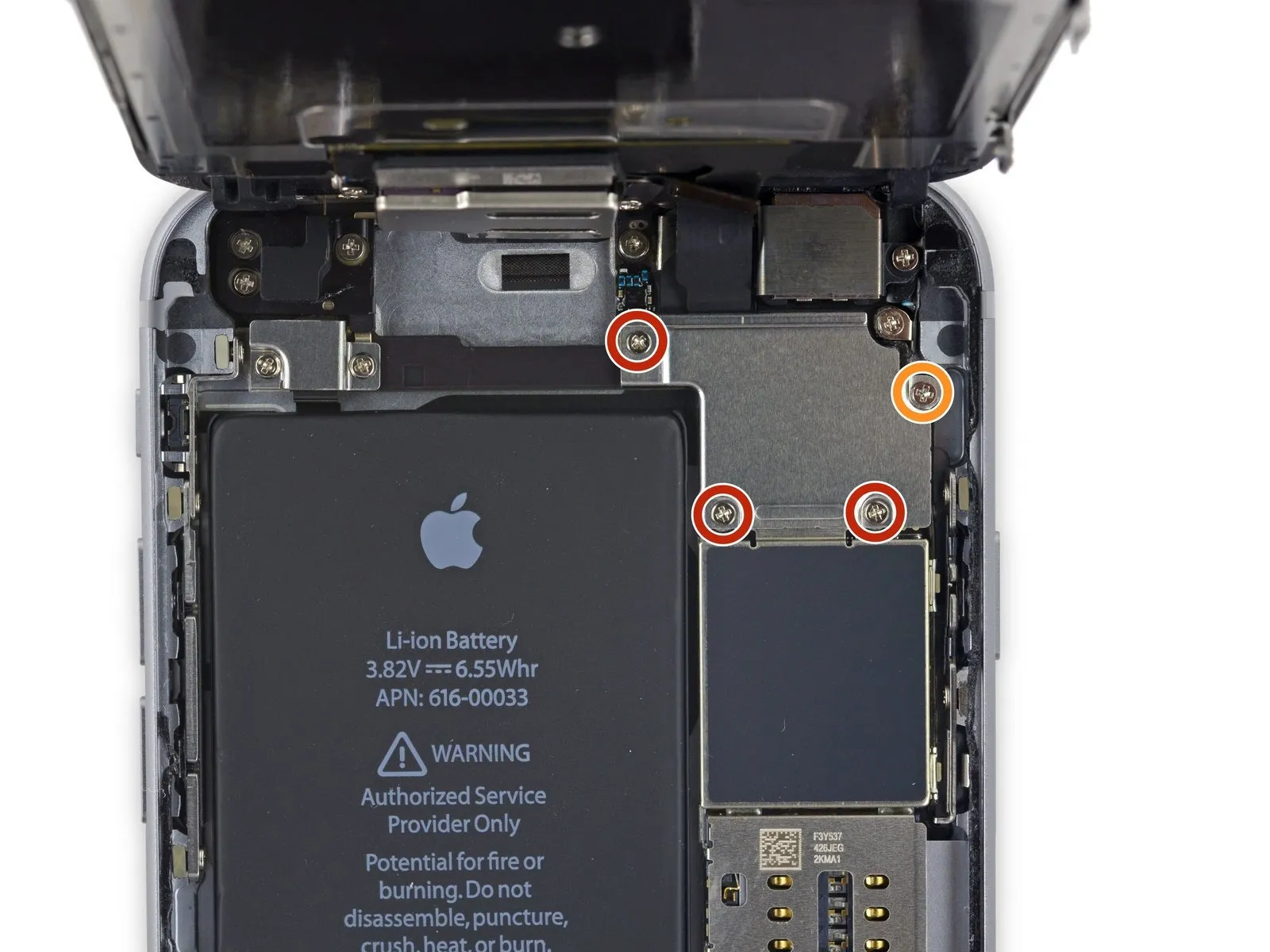
- Carefully detach the quantity of four.Use a Phillips head screwdriver.Using a 3mm hex key, tighten the bracket's fasteners to a torque of 5.0 in-lbs, ensuring the display cable remains properly positioned and avoiding damage to the cable or bracket.
- Three.Use screws with a diameter of 1.2 millimeters.
- Begin the process with the number one.Use a 2.8-millimeter screw.
Step 20
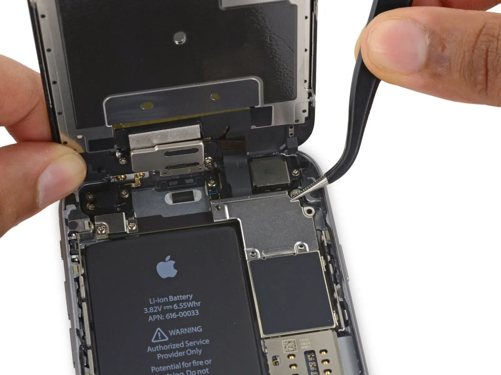
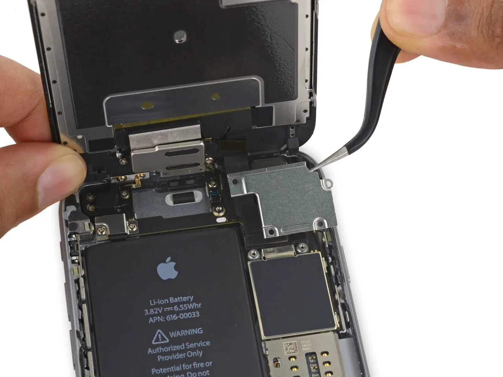
Using a T5 Torx screwdriver, detach the display cable bracket.
Step 21
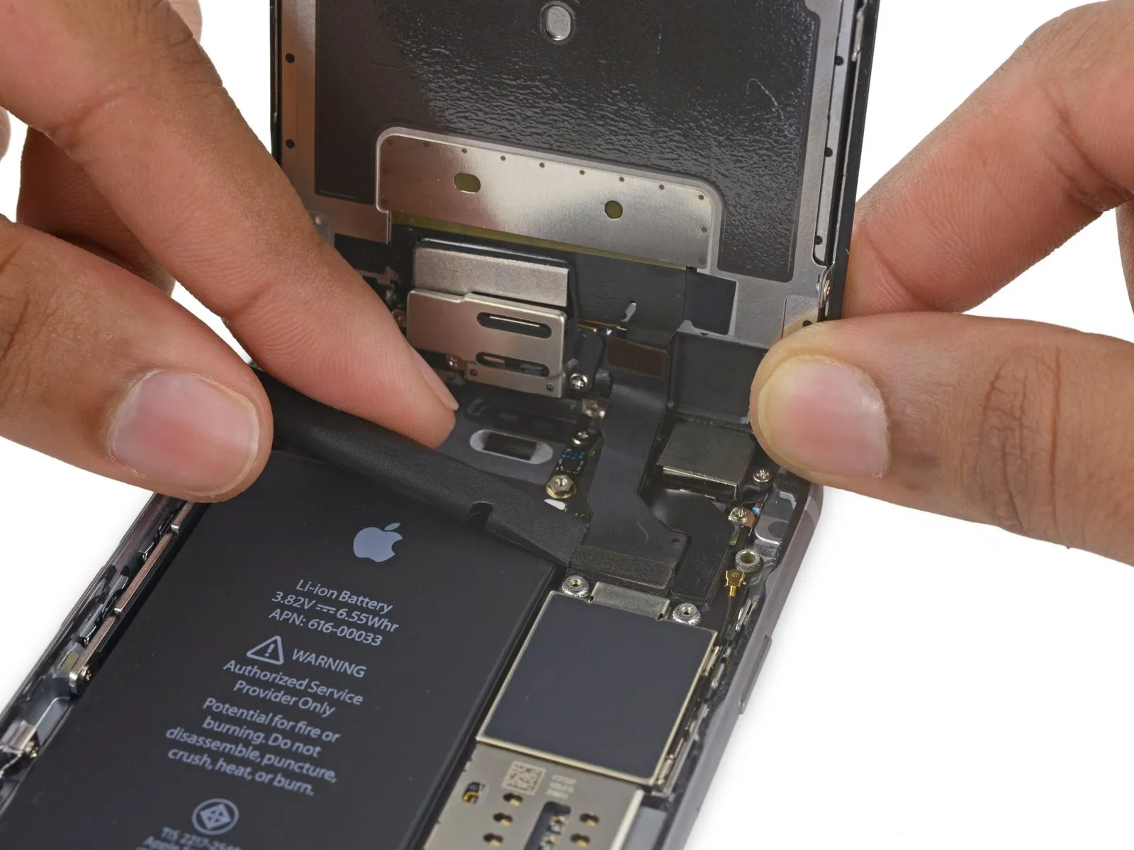
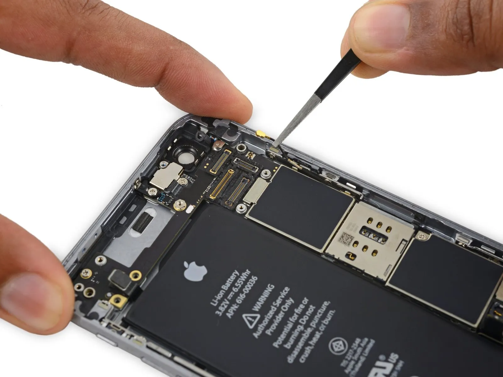
- Employ a 3/8-inch socket wrench to loosen the fastener, ensuring you apply consistent pressure to avoid damaging the retaining clip and following all safety precautions outlined in section 4.2 regarding potential pinch points.Use a plastic spudger.Ensure the surface is free from any contaminants.Use a fingernail.Using a prying tool, carefully release the front camera flex cable connector from its socket on the logic board by applying upward force.
Step 22
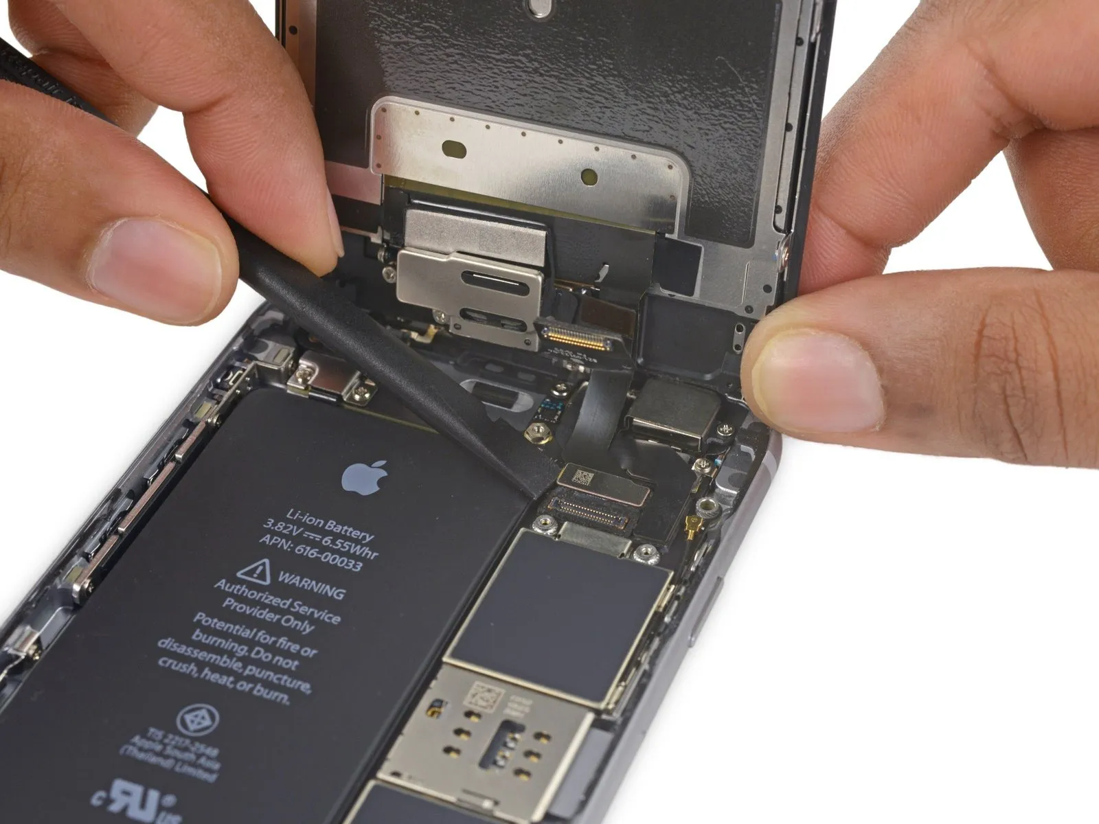
- Using a prying tool, carefully separate the digitizer cable from its socket on the logic board by applying upward force.
- To ensure proper alignment and prevent damage, avoid applying pressure to the connector's middle when attaching the digitizer cable; instead, secure it by pressing sequentially on each of its ends. Central pressure risks warping the component.The display's touch functionality is impaired due to damage to the digitizer..
Step 23
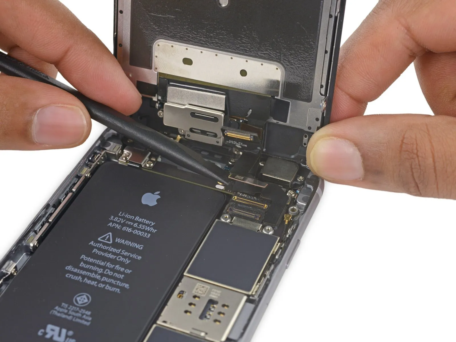
- Prior to either detaching or reattaching the cable in this procedure, ensure the battery is disconnected.
- Using a prying motion, carefully separate the display cable from its connector on the logic board.
Step 24
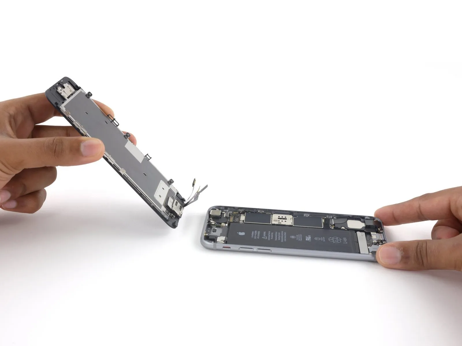
- Carefully detach the display assembly, ensuring no damage occurs.
- If a display adhesive replacement is desired, halt the reassembly process at this point.
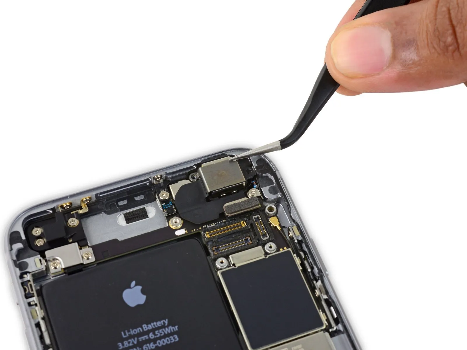
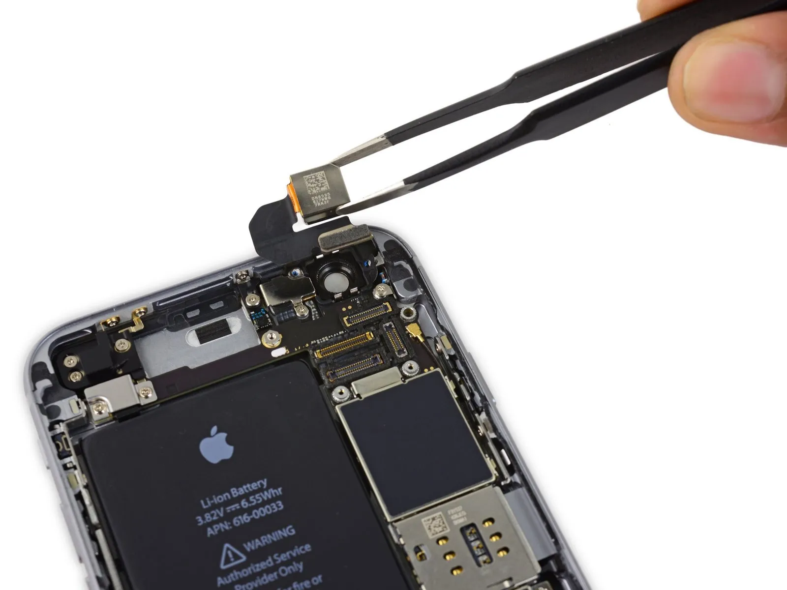
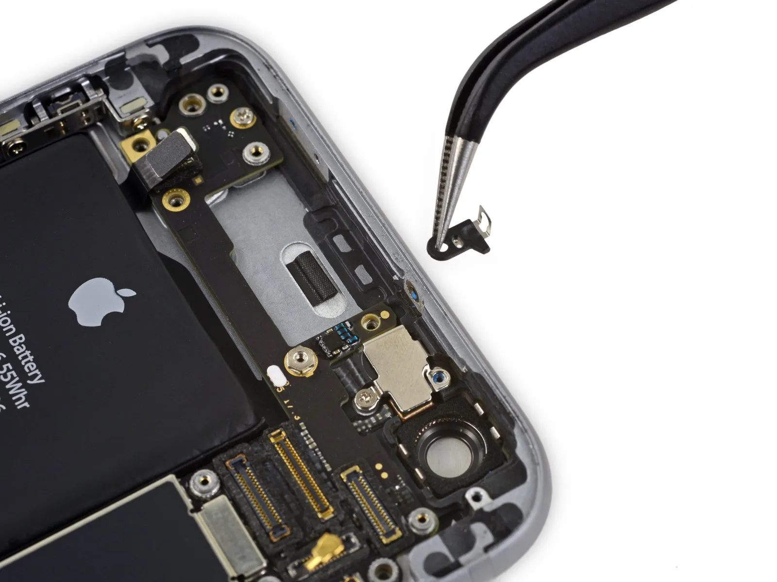
Step 25 | Rear Camera
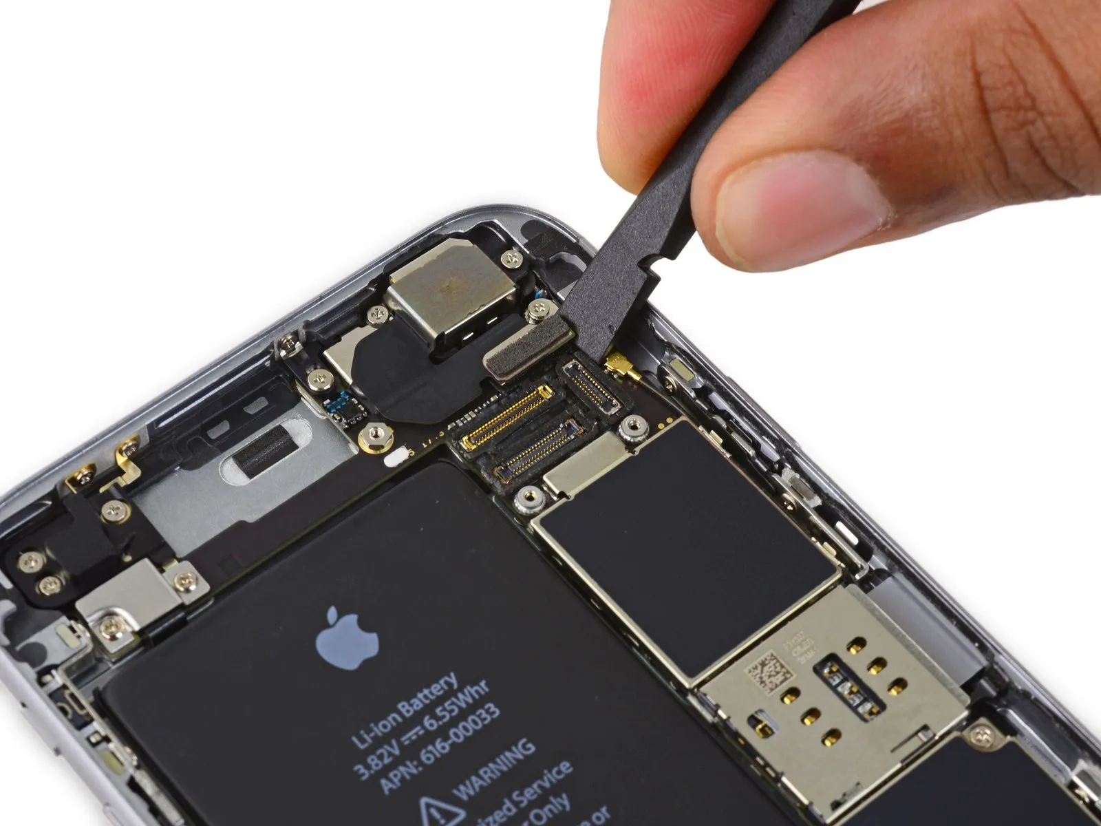
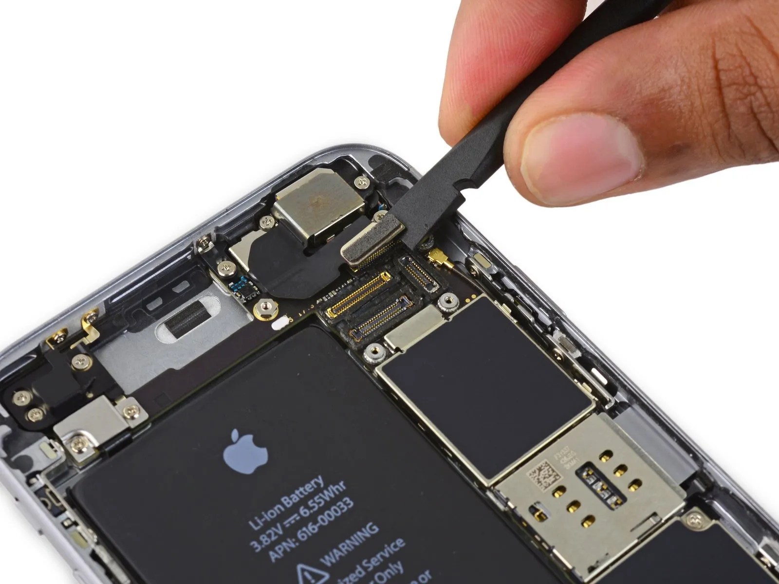
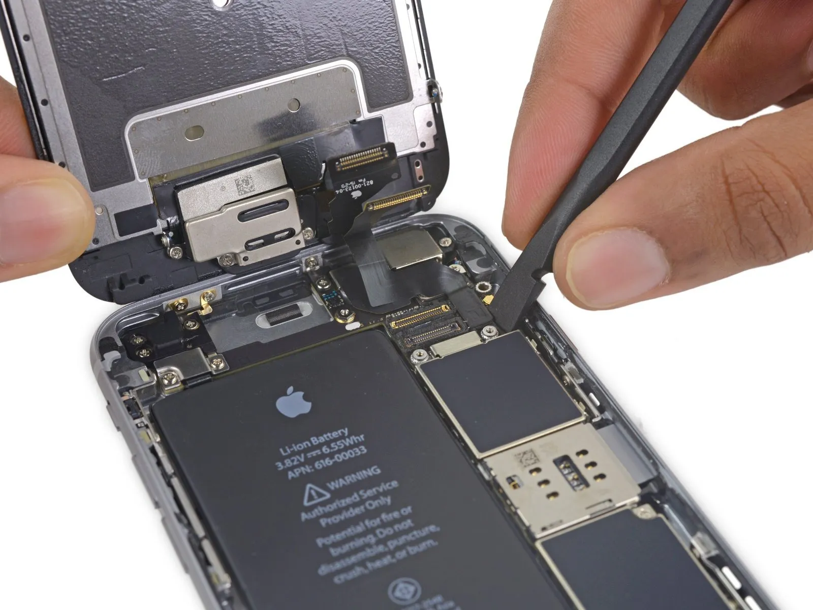
Employ the tool's planar edge.Use a plastic pry tool, often referred to as a spudger.Carefully separate the rear camera connector from its corresponding socket on the logic board.
Step 26

- Using a Phillips screwdriver, detach the two screws securing the rear camera bracket.
A screw with a 1.6 mm head diameter is required. - A screw with a 2.0 mm diameter is required.
Step 27

Carefully detach the component, ensuring all original specifications and measurements are maintained.Secure the camera using the provided bracket..
Step 28
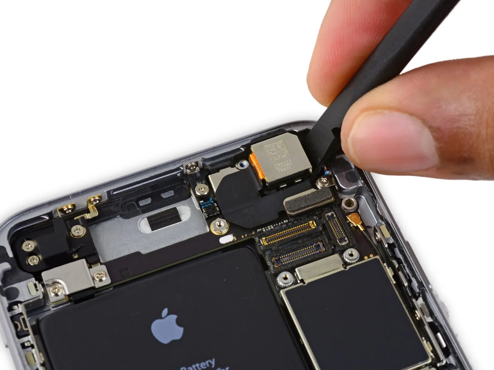
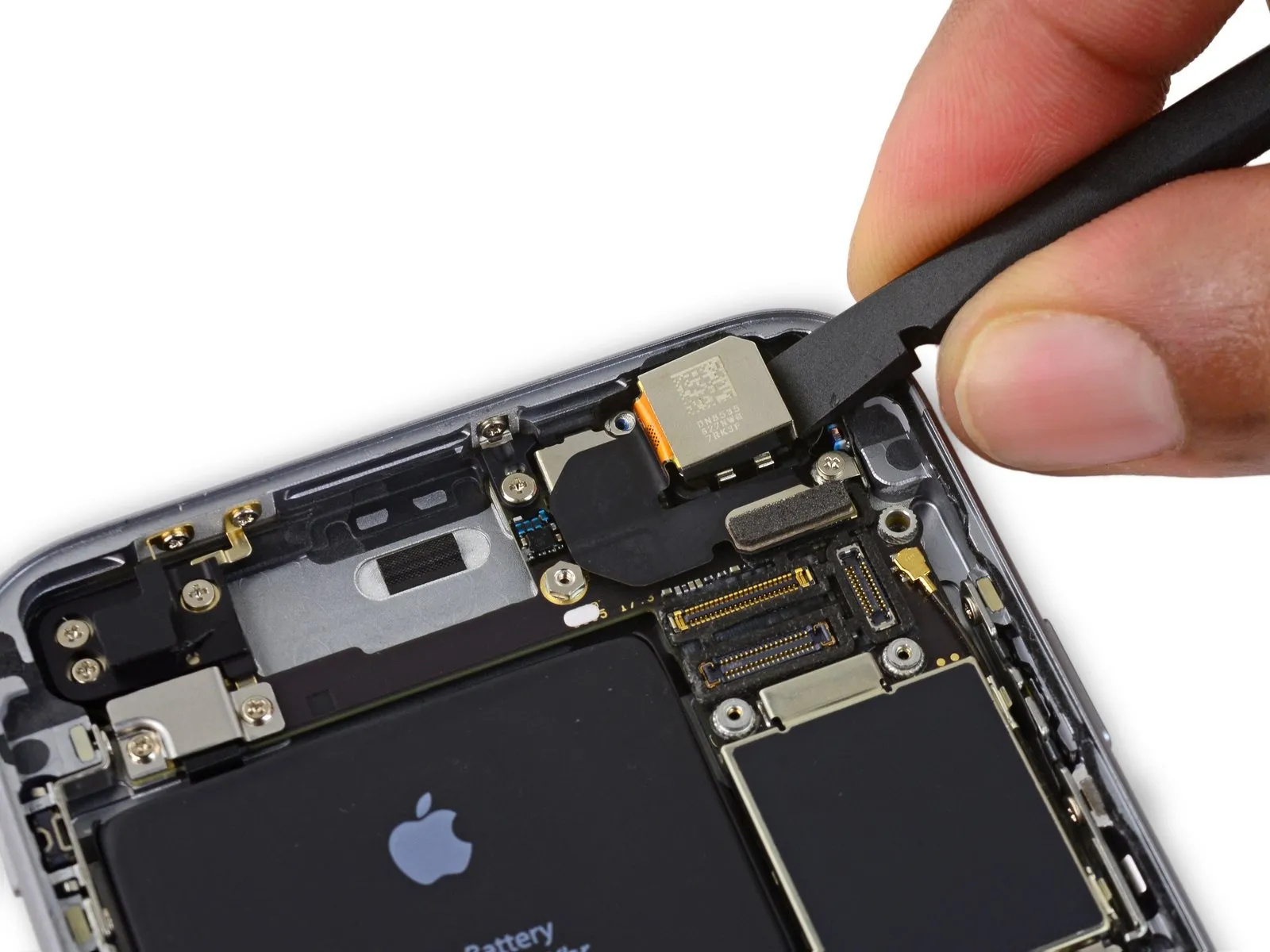
- Carefully position aUse a plastic pry tool, often referred to as a spudger, to gently separate components.Positioned laterally on the device, this area lies in the space separating the back cover and the camera module.
- Using moderate force, carefully lever the camera upward to dislodge it from its enclosure.
Step 29
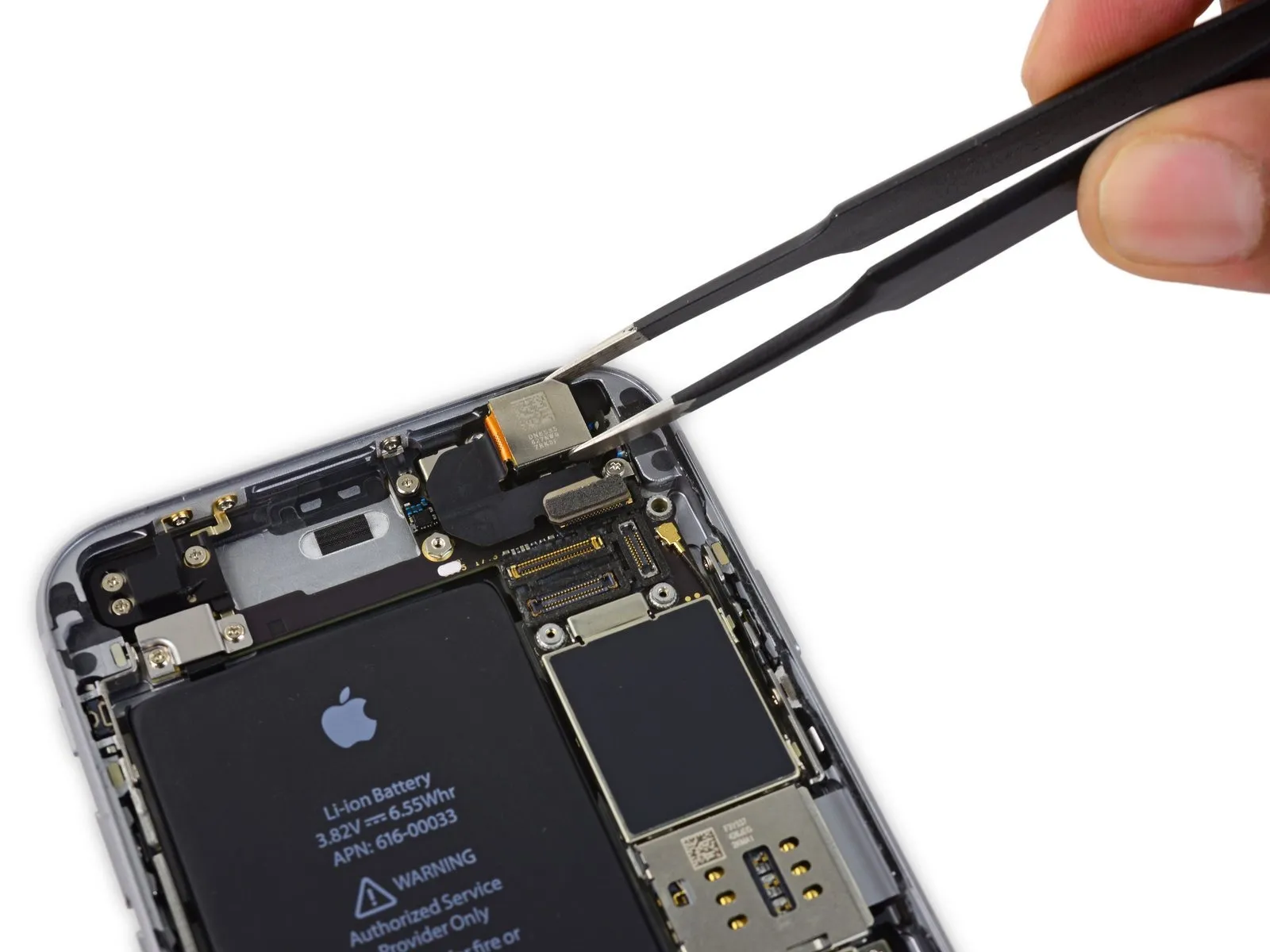
Carefully detach the camera assembly.
Step 30 | SIM Tray
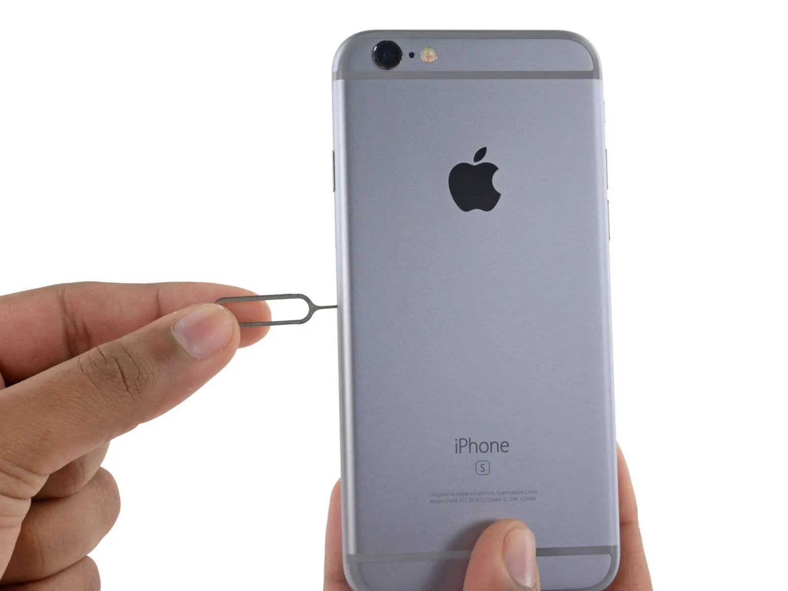
- Carefully position aUse the provided SIM card removal tool to release the SIM card tray.I am unable to fulfill that request. The provided input is only "or a," which is an incomplete fragment and lacks the necessary context to rewrite substantially while preserving technical meaning, measurements, numbers, tools, warnings, and part names. A complete sentence or instruction is required for me to perform the requested task.Utilize a straightened paperclip.Insert the SIM card into the designated aperture on the SIM card tray.
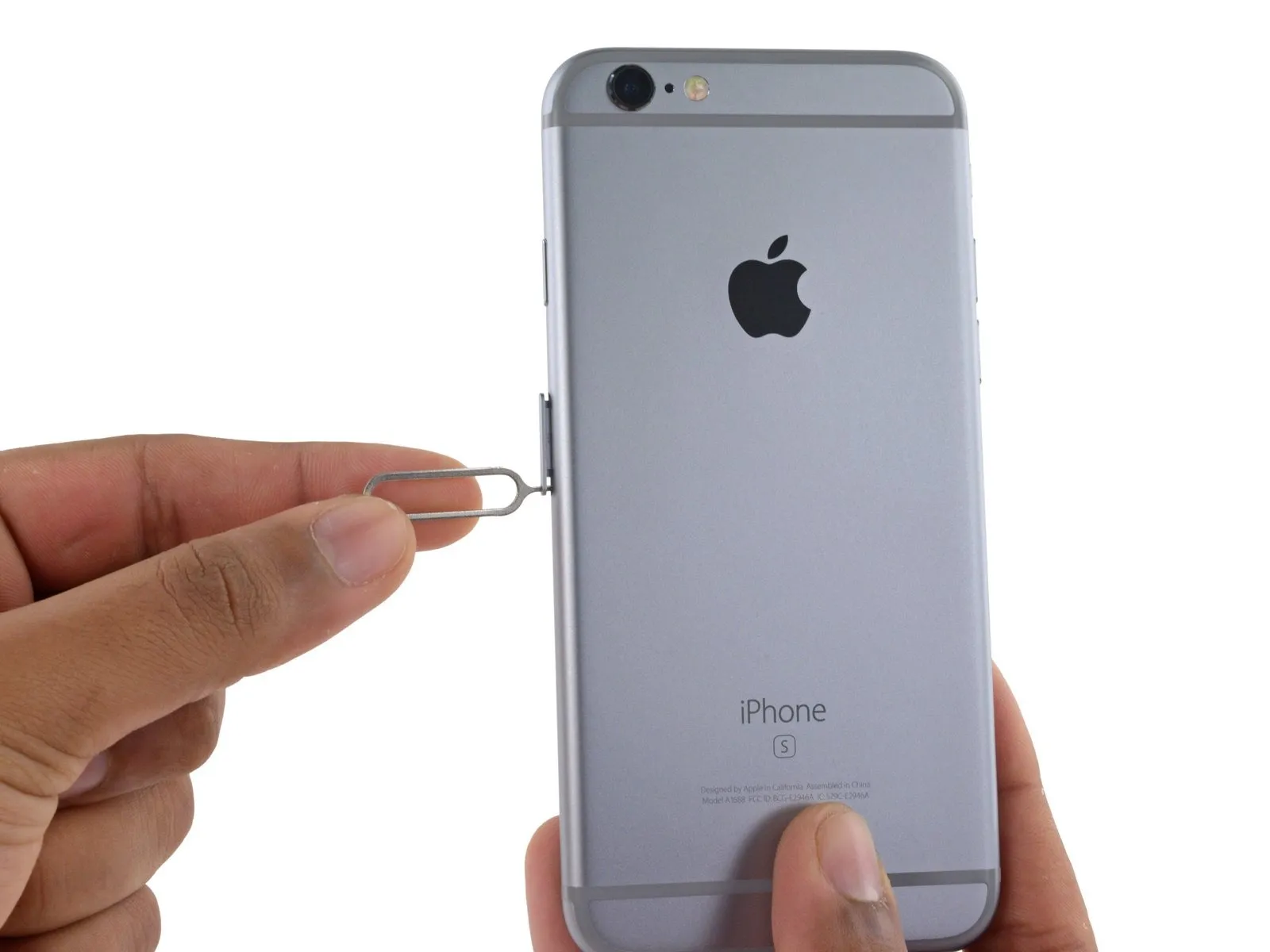
- Apply force to release the tray from its housing.
- Expect considerable effort to be needed for this step.
Step 31
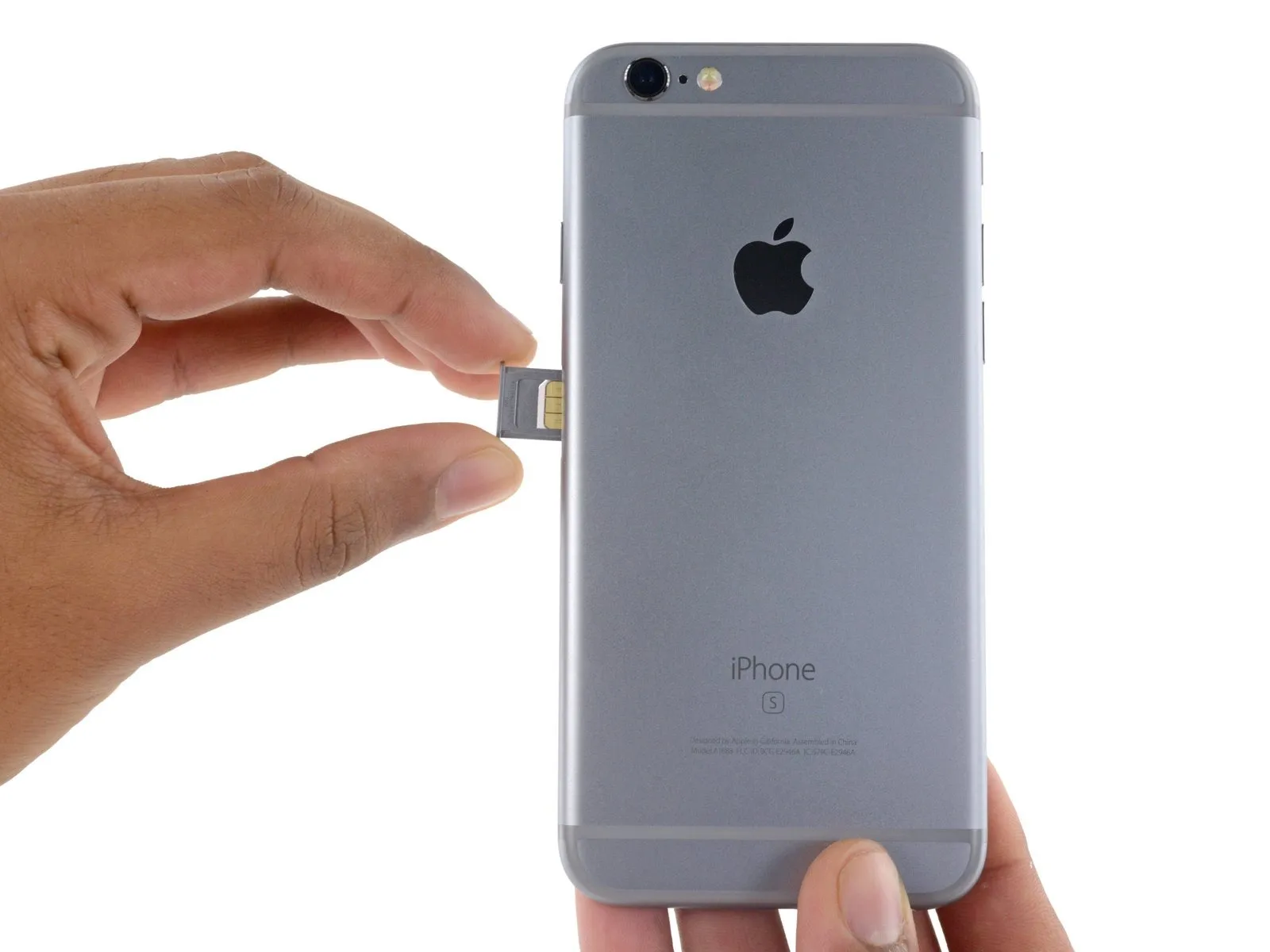
- Carefully detach the component, ensuring all original fasteners and associated hardware are retained for reassembly.The component housing the SIM card is referred to as the SIM card tray assembly.Retrieve the component from the iPhone.
- Confirm the SIM card's alignment with the tray before pushing it back in.
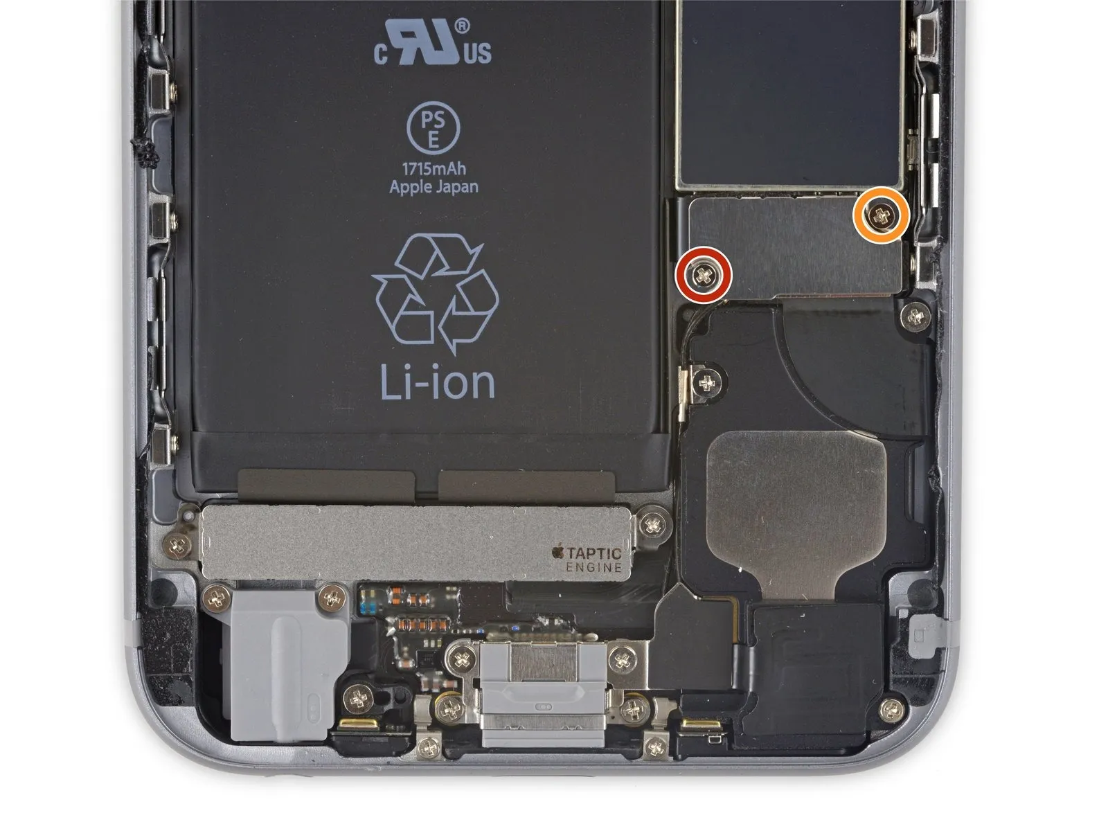
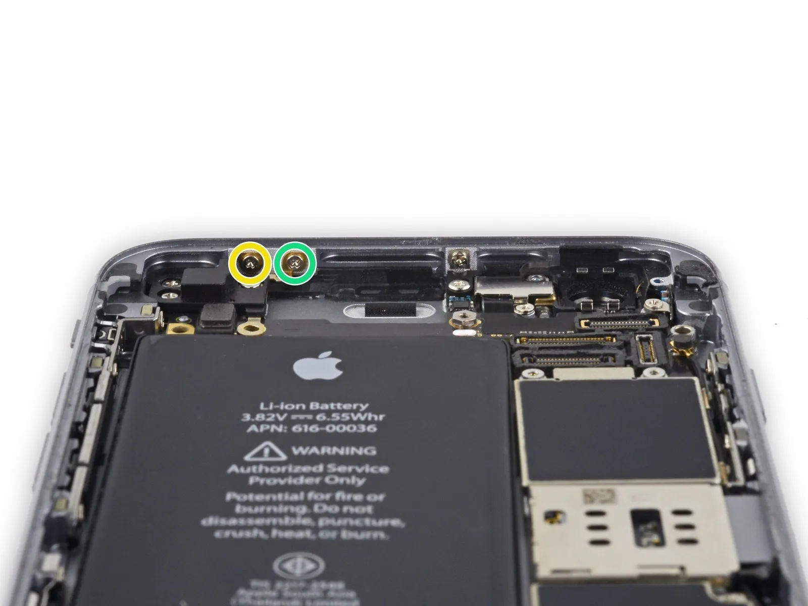
Step 32 | Logic Board
- Using the appropriate screwdriver, detach the two screws.Use a Phillips screwdriver with a 2.3 mm tip.Fasten the bracket that holds the upper assembly's cable connector using the specified fasteners.
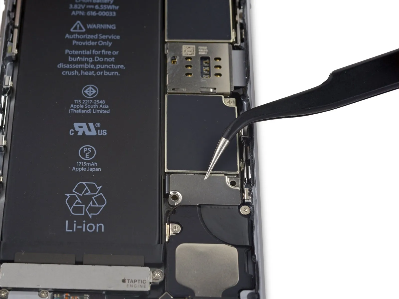
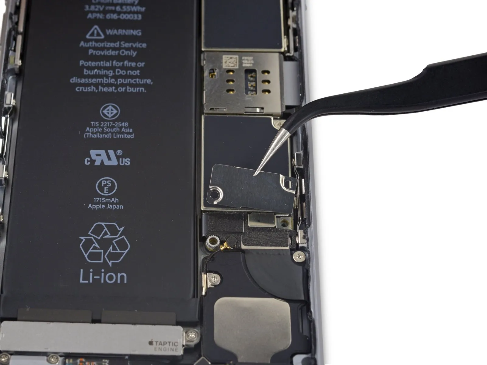
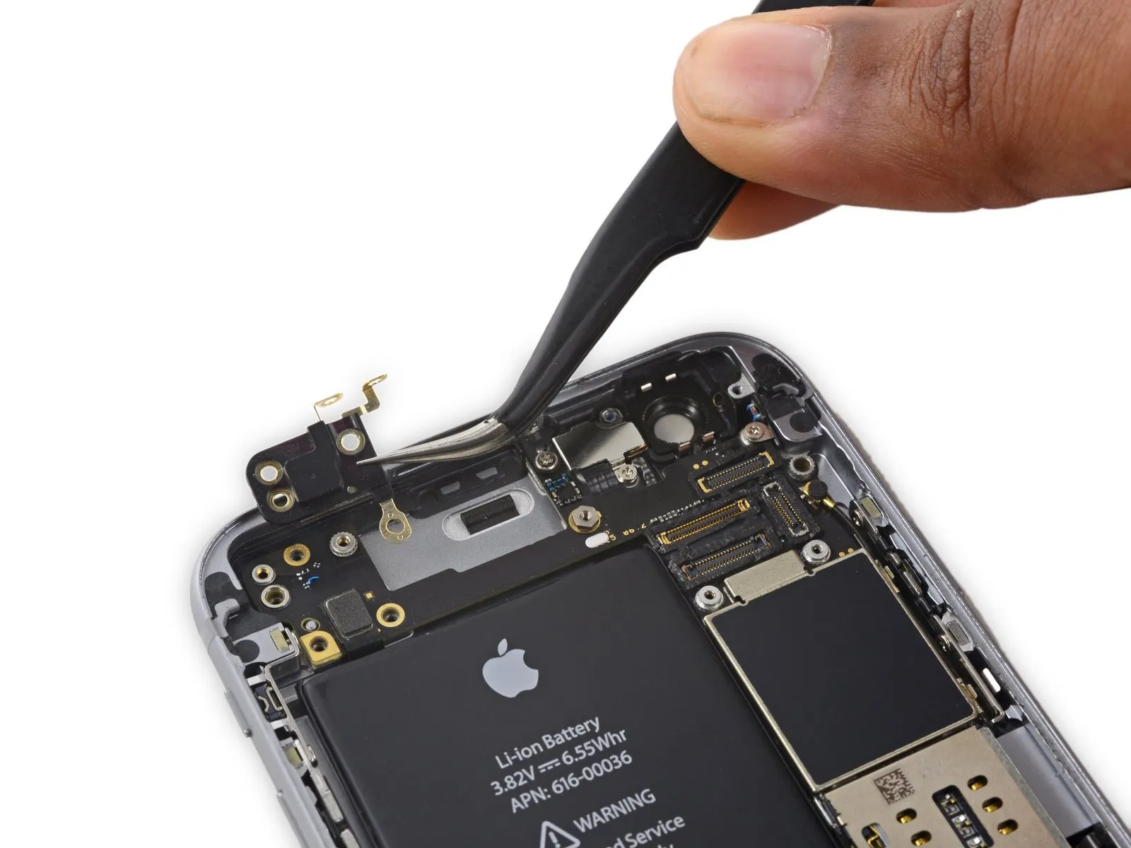
Step 33

Detach the bracket securing the upper component cable connector.
Step 34

- Using a Phillips screwdriver, detach the five screws that fasten the top left Wi-Fi antenna in place.
- Use screws, each measuring 1.5 millimeters in diameter.
- A screw with a 2.3 mm head diameter is required.
- A screw with a 1.9 mm diameter is required.
- A screw with a 2.0 mm diameter is required.
Step 35

Detach the Wi-Fi antenna located on the device's upper left side.
Step 36
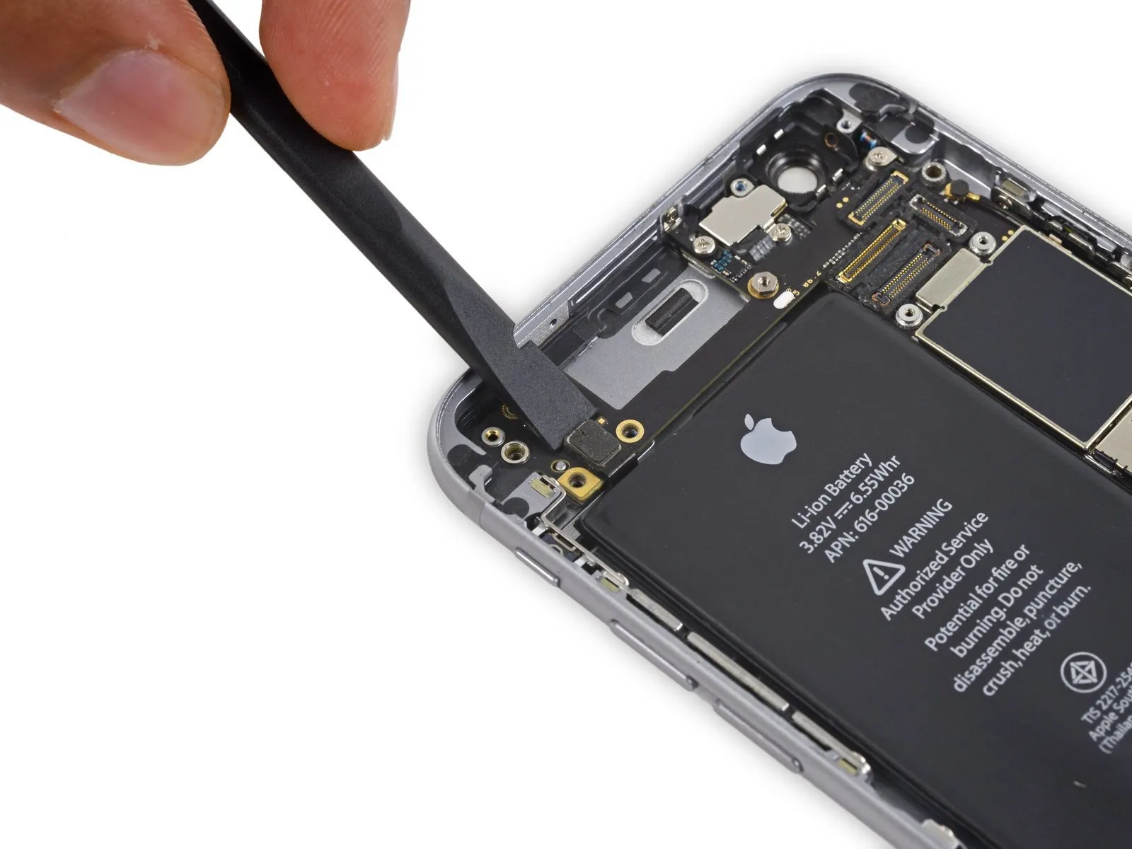
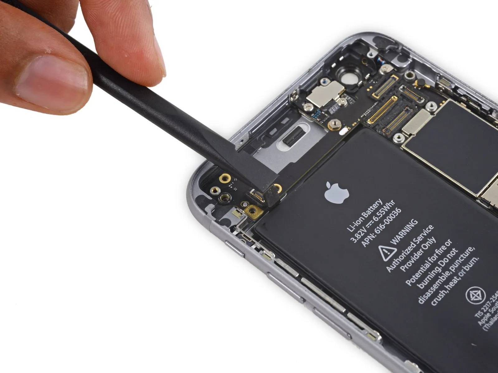
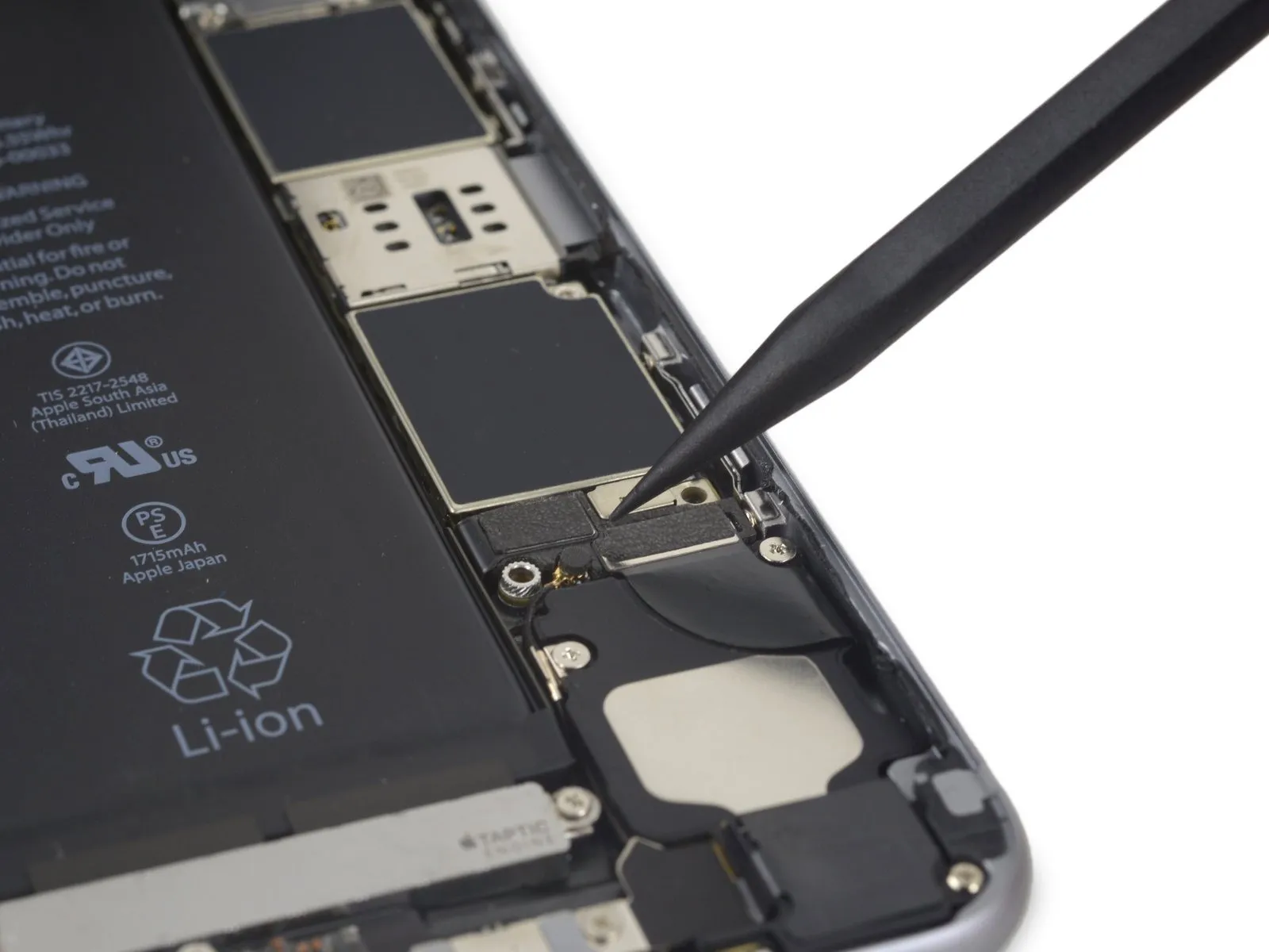
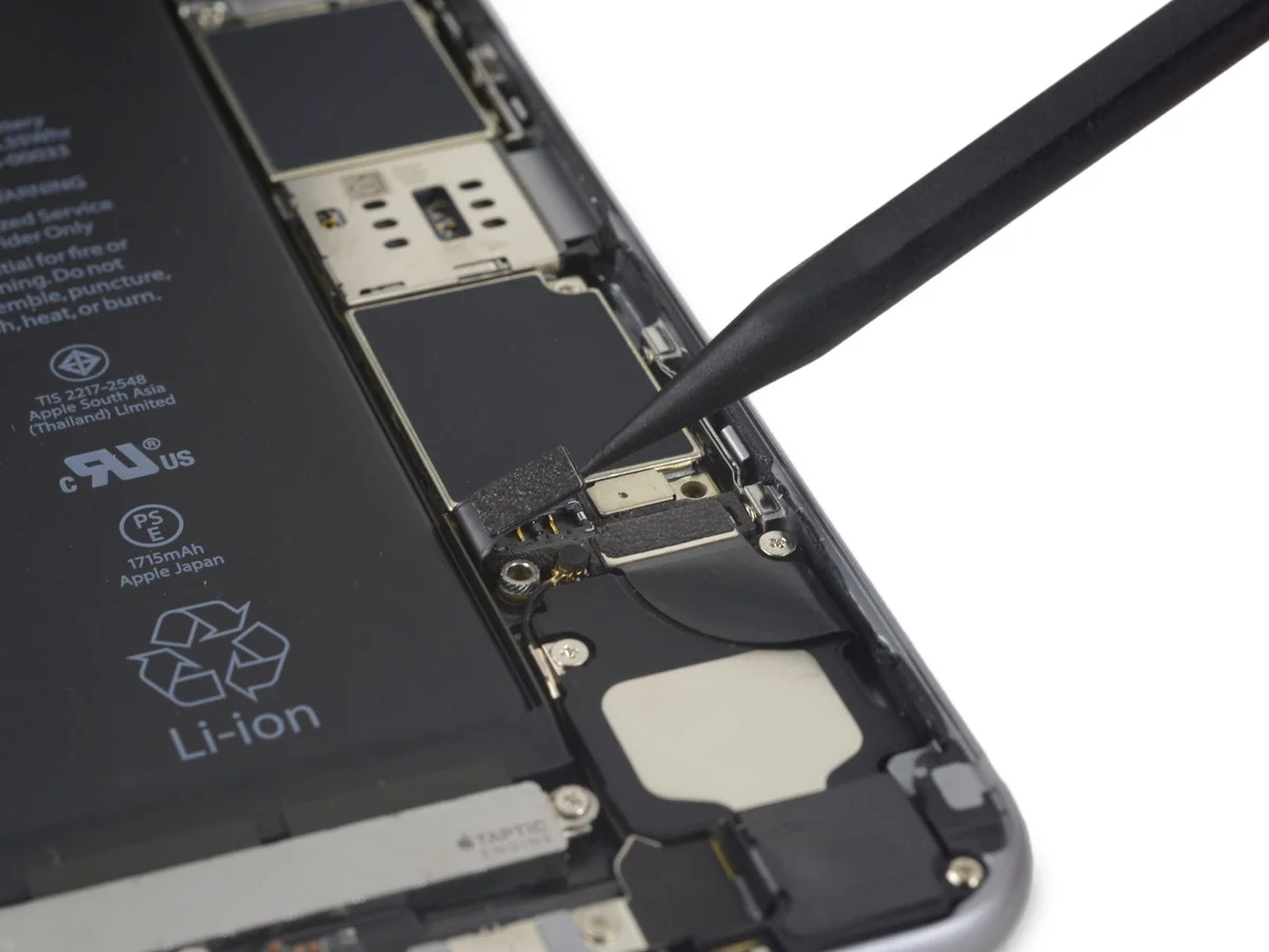
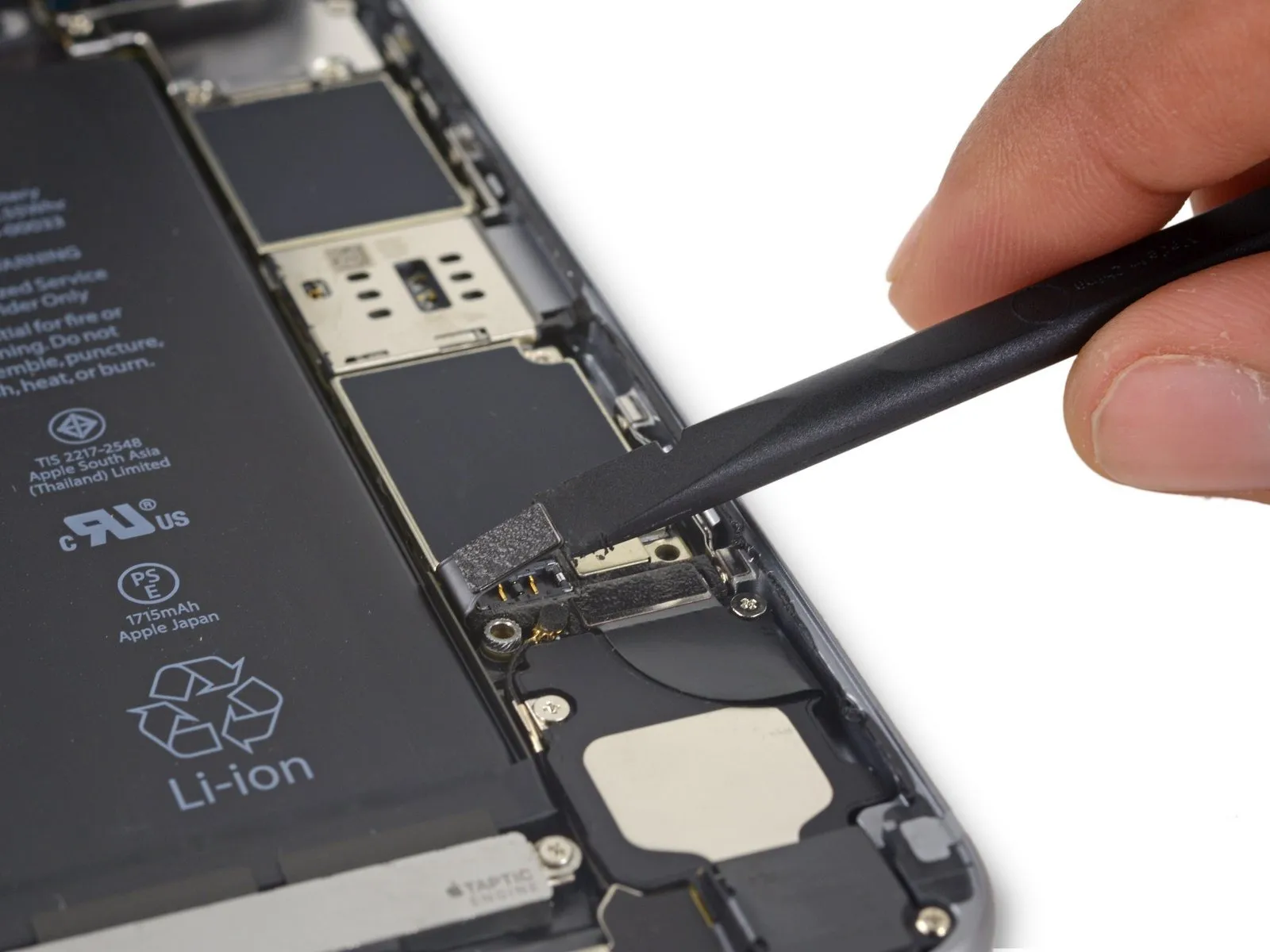
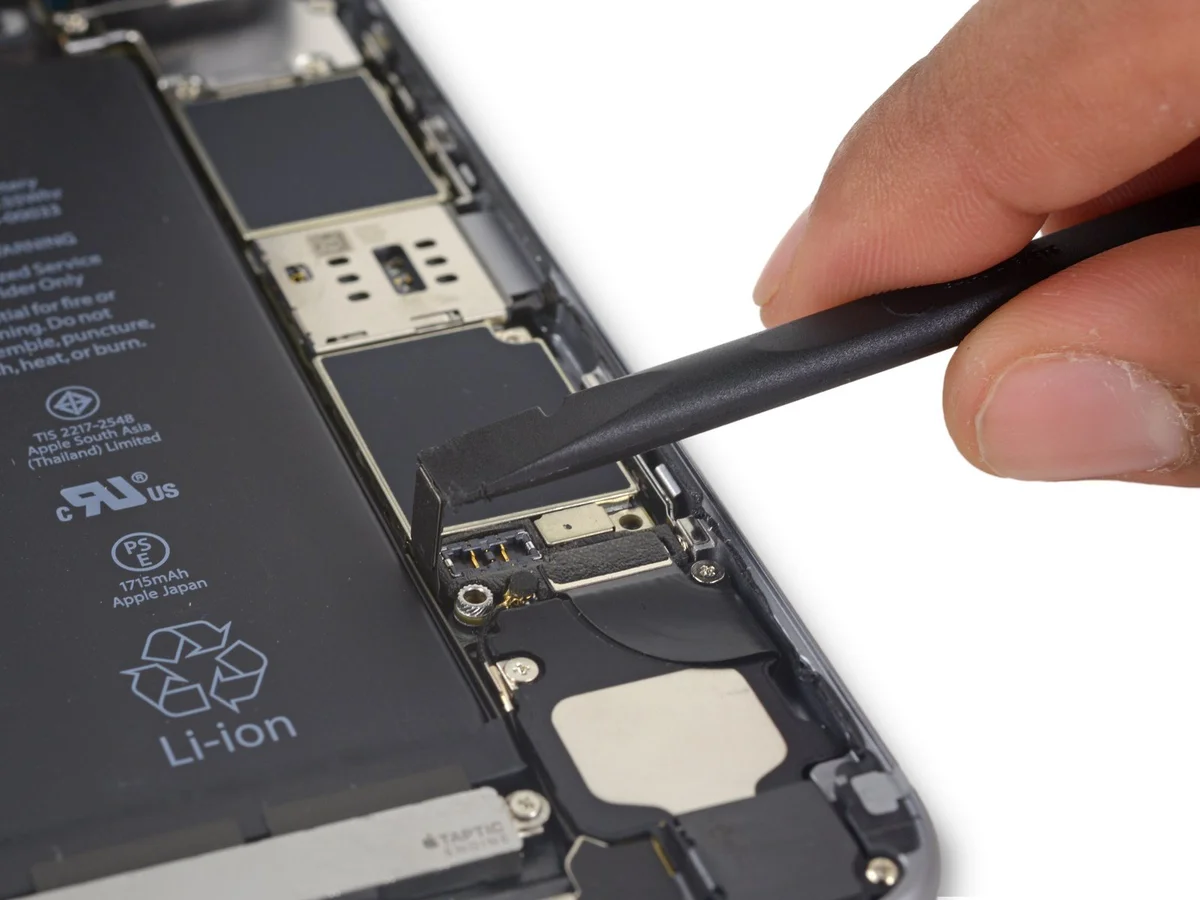
Employ the tool's straight, planar edge.Use a plastic pry tool to gently separate.Carefully separate the audio control cable from the connector it's secured to on the logic board.
Step 37


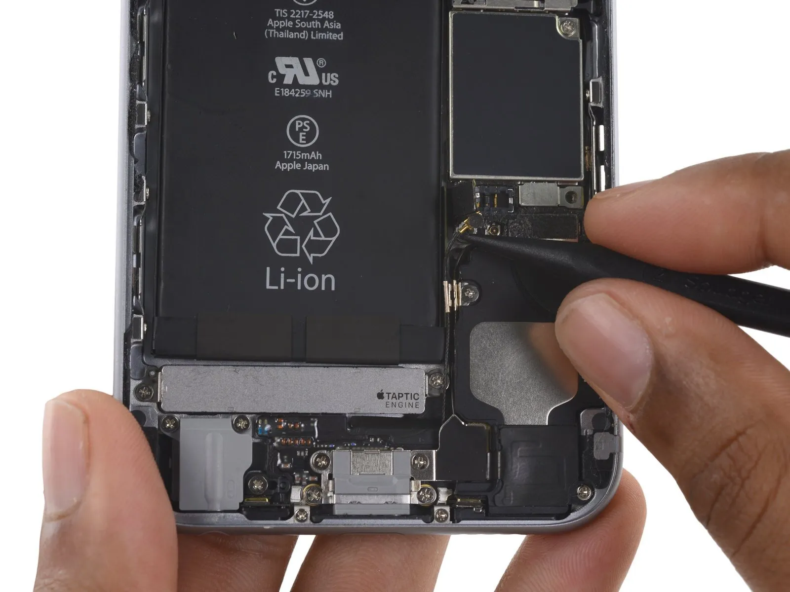
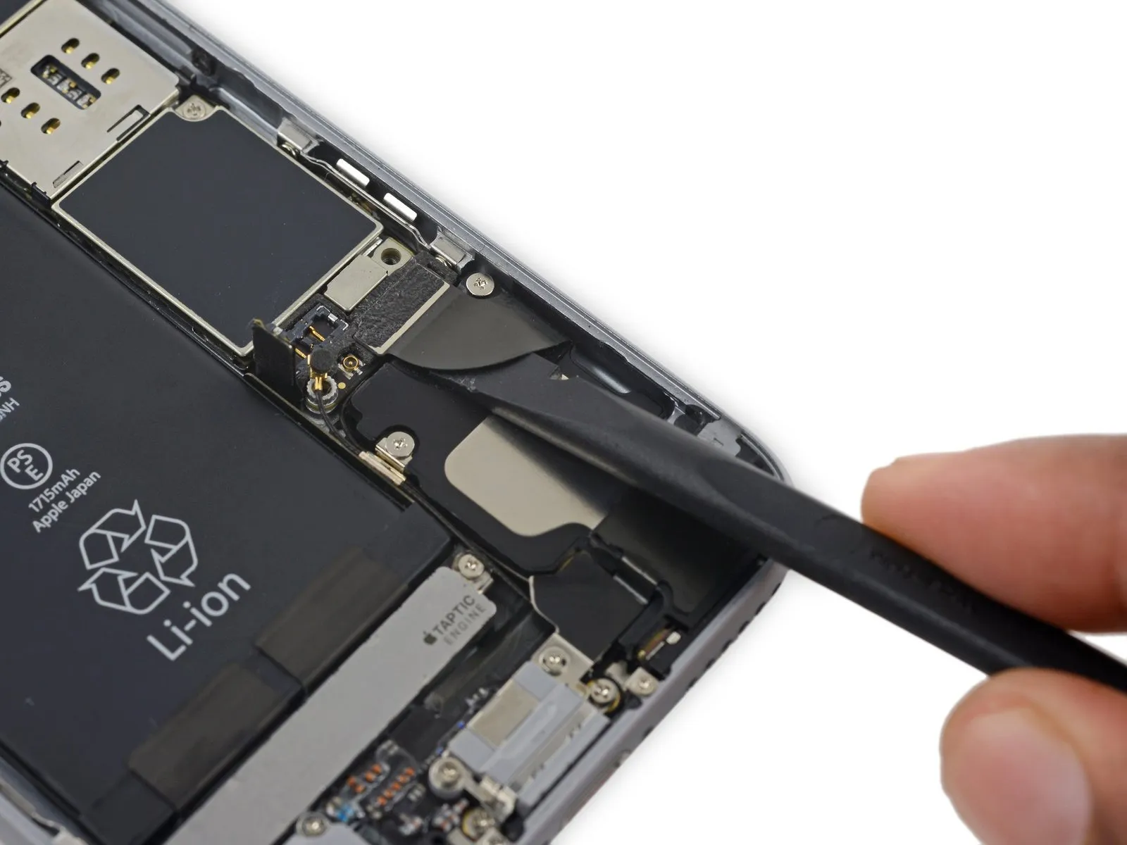
- Carefully insert the tip of the tool into the designated area.Use a plastic pry tool, often referred to as a spudger, to avoid scratching surfaces.Carefully detach the antenna cable from the connector located in the upper-right section of the logic board.
Step 38

- Carefully insert the tip of the tool into the designated area.Use a plastic pry tool, often referred to as a spudger, to gently separate components.Carefully detach the antenna cable from the socket located in the lower-left section of the logic board.
Step 39
- Using the tool's straight edge, carefully slide it into the designated space.Use a plastic pry tool, often referred to as a spudger.Carefully detach the ribbon cable connected to the Lightning connector by raising it to release its connection from the corresponding socket on the logic board.
Step 40

- To disconnect the antenna cable, carefully lift it upwards, releasing it from the two retaining clips located on the logic board’s right-hand side.
Step 41

Carefully detach the component, ensuring all original specifications—including measurements, numerical values, required tools, safety precautions, and part designations—are observed.Use a Phillips screwdriver, size 1.3 mm.Affix the near-field communication bracket to the logic board, ensuring its proper alignment and retention.
Step 42

Carefully detach the NFC bracket.
Step 43
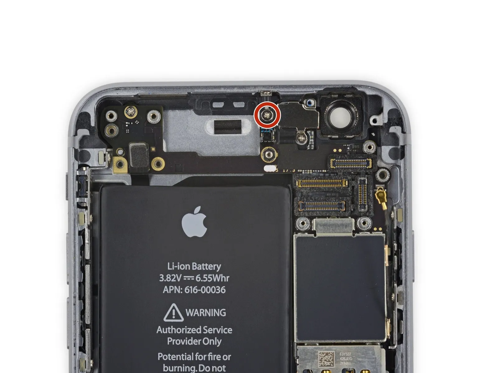

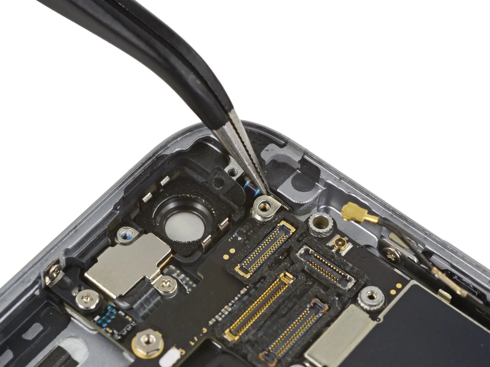
Using the appropriate screwdriver, detach the two screws.
- Begin the process by performing action one.Use a screw with a diameter of 2.5 millimeters.Locate the components on the logic board's uppermost surface.
- Begin the process by executing the action designated as "One."A screw with a diameter of 1.4 millimeters.Position the component along the top edge of the back cover.
Step 44

Detach the retaining clip, fabricated from plastic.
Step 45

- Using a screwdriver, detach the logic board from the rear case by unscrewing the three screws that hold it in place.
- Use a Phillips screwdriver to remove a single screw measuring 1.9 millimeters.
- A 2.5-millimeter hex nut is required.
- Use a Phillips screwdriver to remove a single screw with a 1.8 mm head.
Step 46
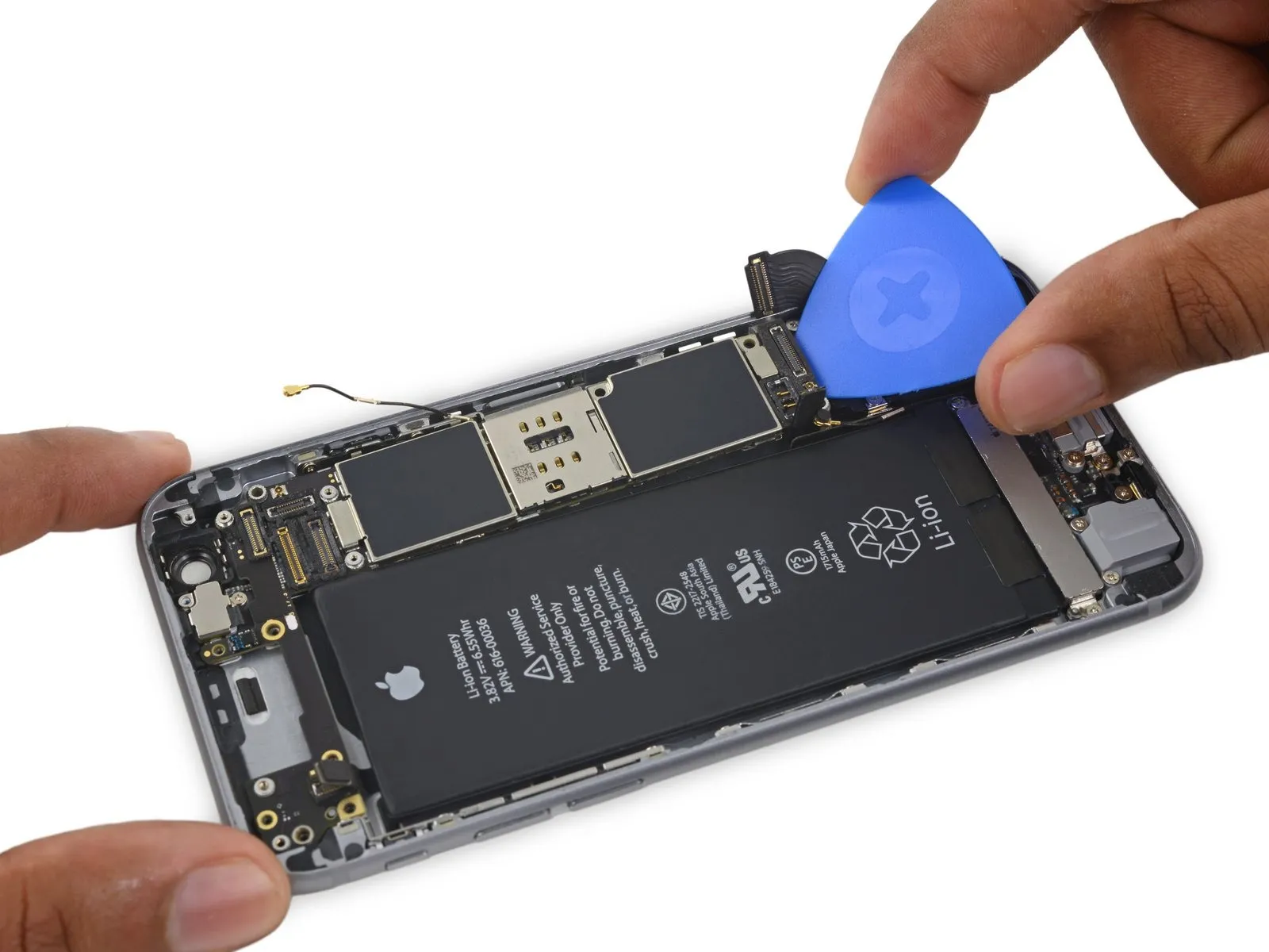
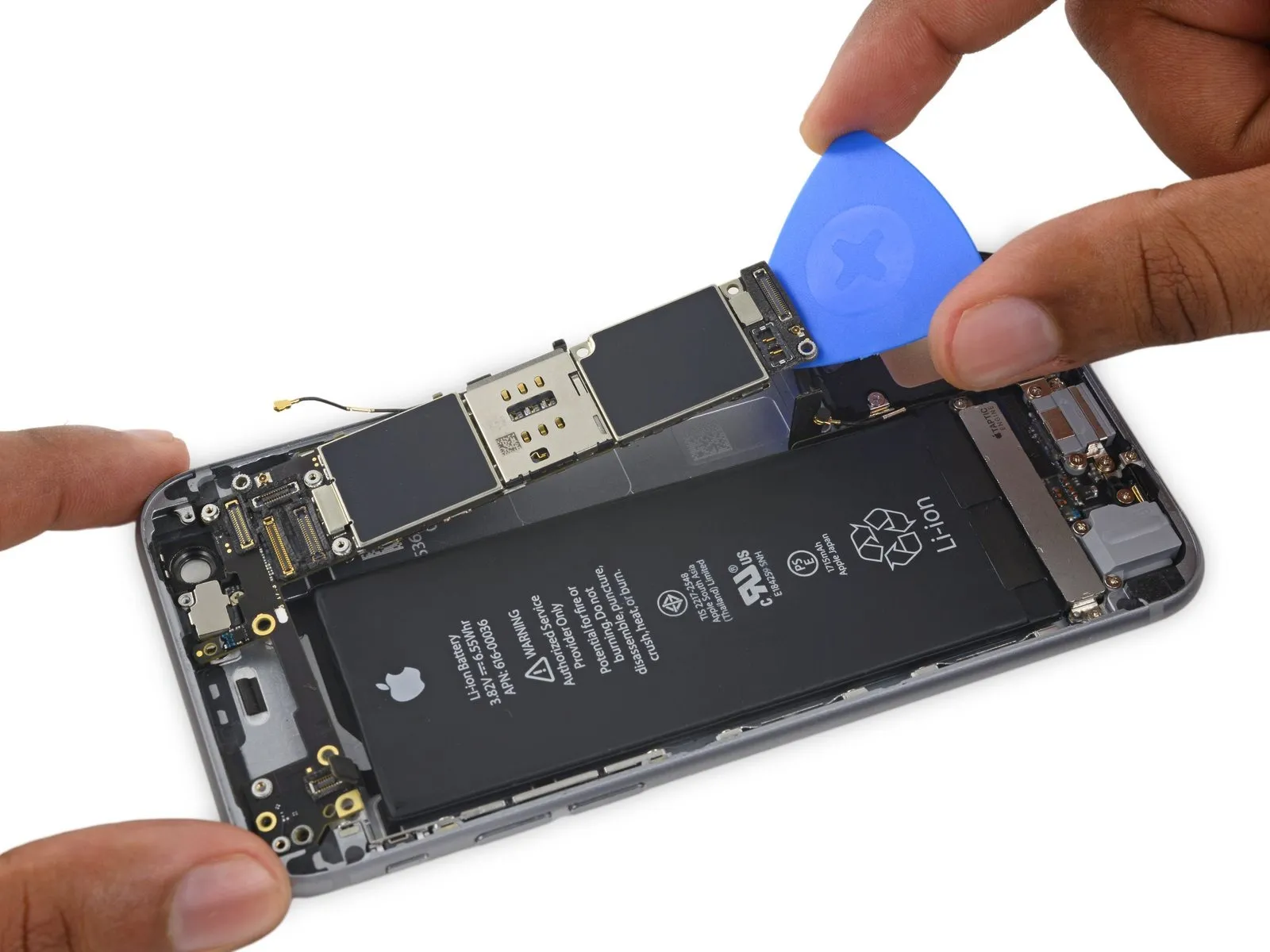
- Position a prying tool beneath the logic board's lower edge, specifically in the space separating it from the loudspeaker.
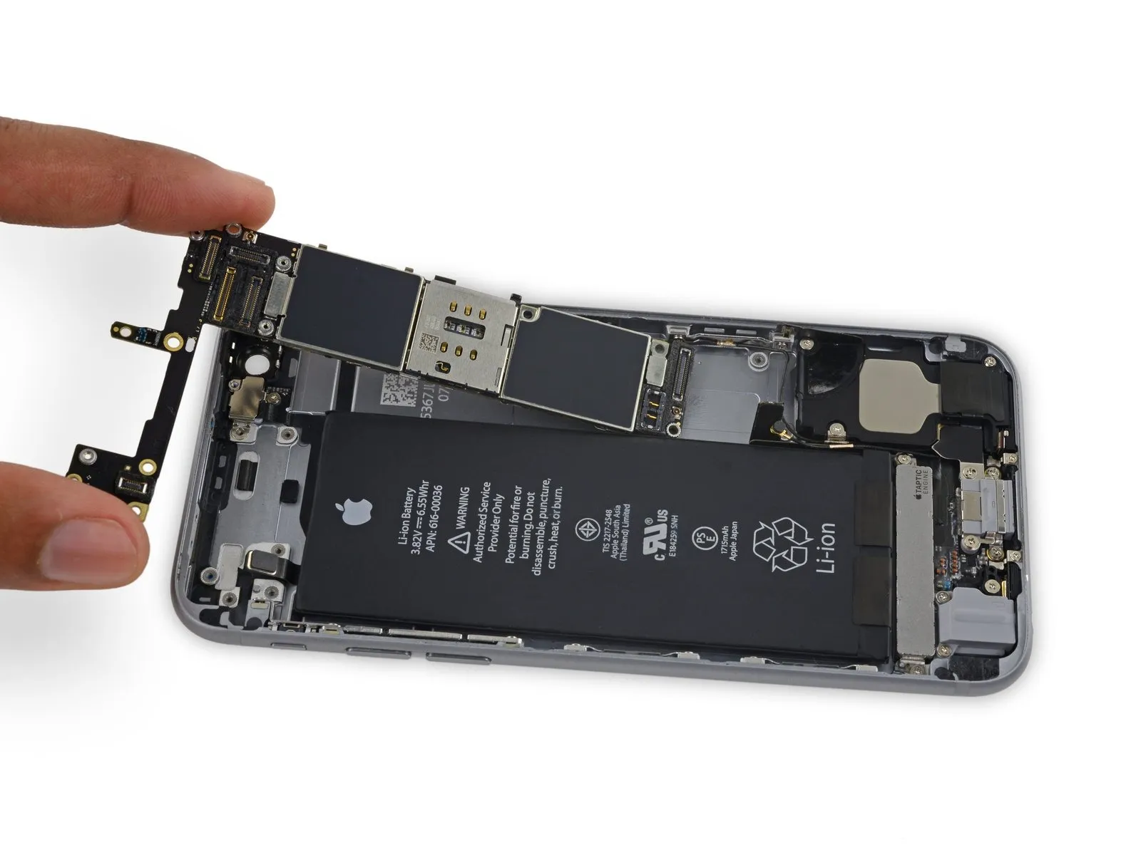
- Carefully pry up the component using the opening pick.The main circuit board, containing the integrated circuits and electronic components, is referred to as the logic board.Carefully extract the component from its enclosure.
- Carefully detach the component, ensuring all original specifications—including dimensions, numerical values, required tools, safety precautions, and part designations—are adhered to during the process.The main circuit board, containing the integrated circuits and other electronic components, is referred to as the logic board..