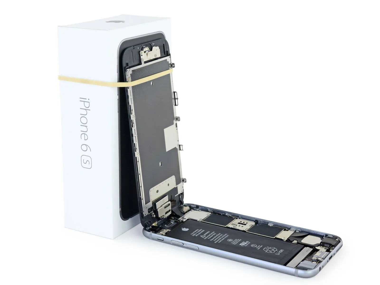
iPhone 6s Battery Replacement
Follow these instructions to restore functionality to yourApple iPhone 6sReplace the existing battery with a fresh one, and if you observe any signs of swelling on the battery, exercise caution.
To avoid harming the display cable connections, carefully remove the front panel assembly. Alternatively, if you are confident in your ability to gently support the display, you may proceed with battery removal without detaching the front panel.Using the pentalobe screwdriver, carefully unscrew the five screws, each measuring 1.5mm, securing the bottom edge of the device, then gently lift the display assembly to access the internal components.If you choose not to detach the display assembly, proceed immediately to the battery disconnection procedure.
- To ensure peak functionality, following the steps in this guide, condition the new battery by initially charging it fully, and continuing the charging process for a minimum of two additional hours. Afterward, utilize yourCarefully handle the device, referred to as an iPhone.Allow the device to power down completely when the battery is depleted, then fully recharge it without interruption.
- This procedure also covers the replacement of the battery connector bracket.
Step 1 | Pentalobe Screws
- Securely clamp the workpiece using a vise or similar fixture, ensuring it is held firmly and preventing movement during the subsequent operation.Using appropriate tools, carefully measure and adhere to all specified dimensions and safety precautions.
- To prevent a potential fire or explosion hazard from the lithium-ion battery during disassembly, ensure its charge level is reduced to less than 25% beforehand; a fully charged battery poses a risk of ignition if damaged.
- To prevent electrical shock or damage, ensure the iPhone is completely de-energized prior to starting the repair process.
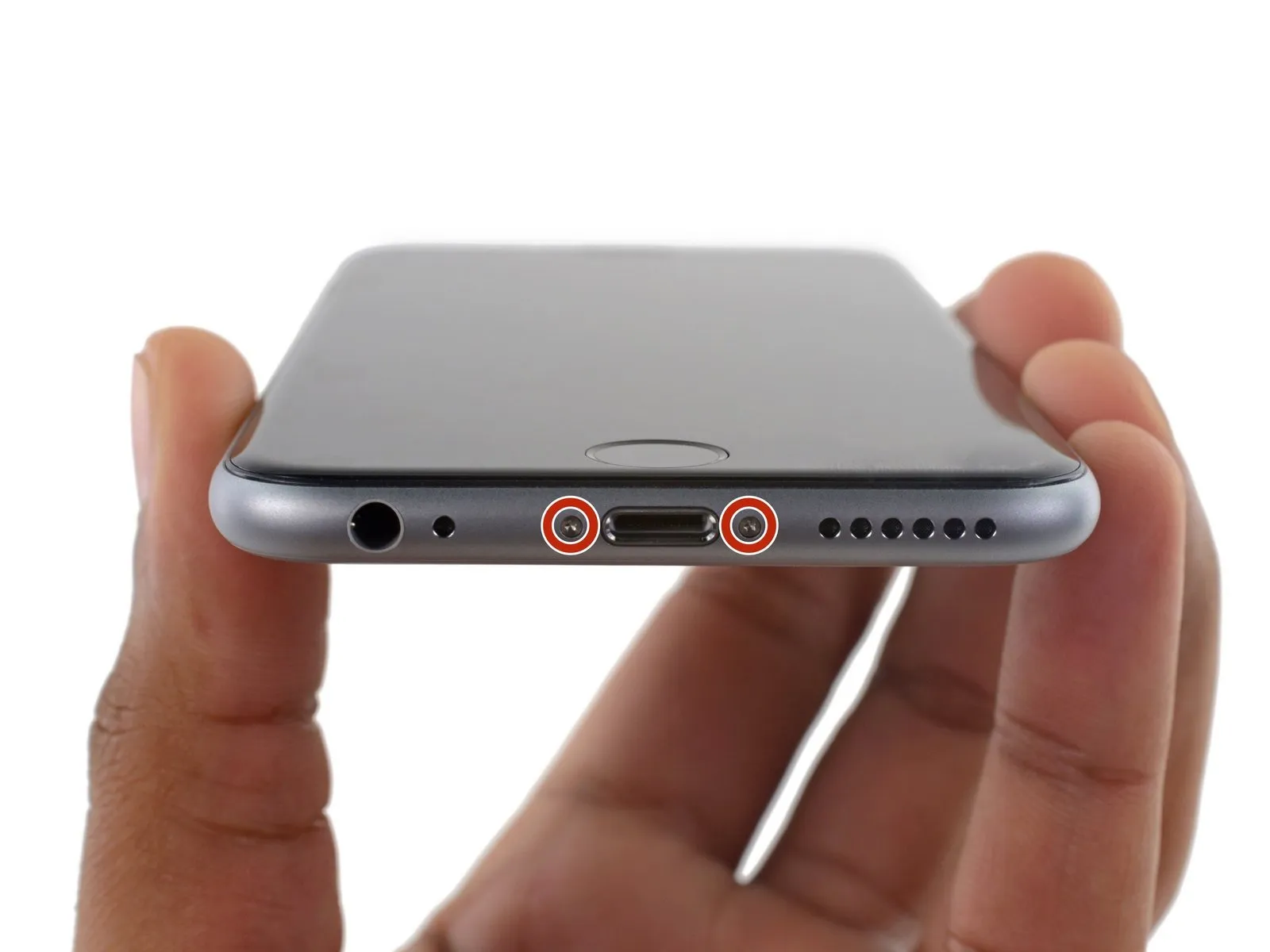
- Detach the pair of fasteners.Use a screwdriver with a 3.4 mm P2 Pentalobe bit to loosen the screws.Locate the two speaker grilles situated along the lower edge of the iPhone, flanking the Lightning connector.
Step 2 | Anti-Clamp instructions


- Carefully clamp the component, ensuring a secure grip, then apply a force of 150 Newton-meters using a torque wrench.Using the specified tools, carefully measure and adhere to all dimensions and safety precautions listed.
- To simplify the opening process, the following two steps utilize the Anti-Clamp tool, a custom-designed aid; if you do not have this tool, proceed to the instructions three steps further down.
- Refer to the accompanying guide for detailed procedures regarding Anti-Clamp operation.
- To release the Anti-Clamp's arms, move the blue handle in a rearward direction.
- Position the arms so they extend across the iPhone's left or right side.
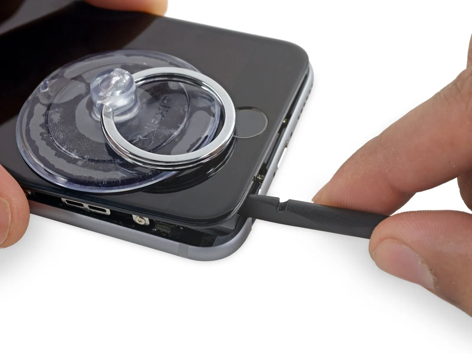
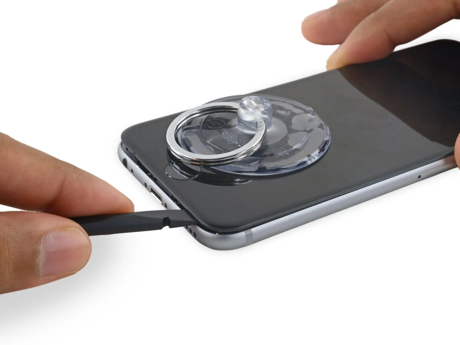
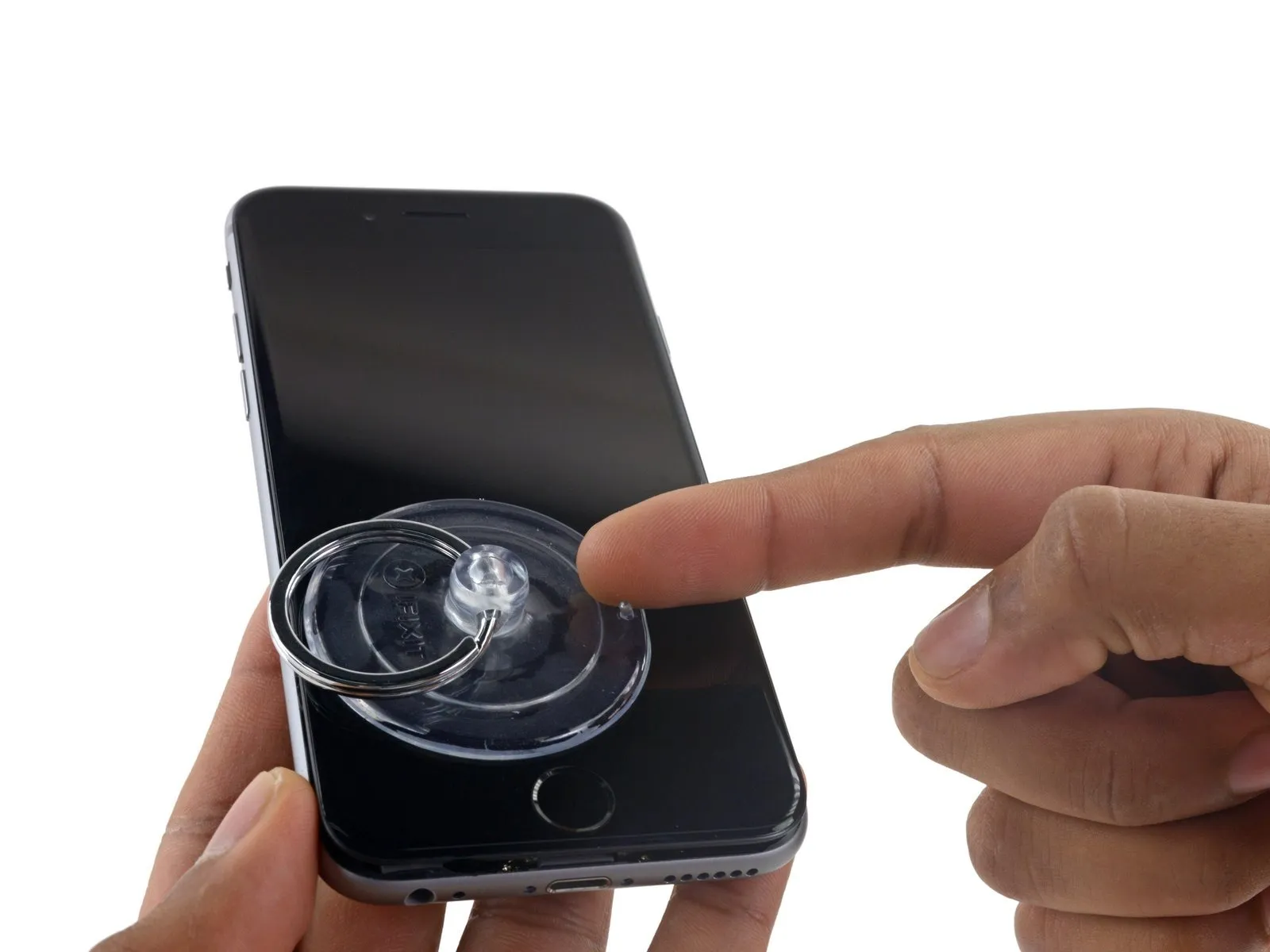
- Secure the iPhone by placing suction cups—one on the front surface and one on the rear—close to the lower edge, situated directly above the home button.
- Apply vacuum by pressing the cups firmly against the surface needing treatment.
- To improve the Anti-Clamp's grip on your iPhone if the device's exterior feels excessively smooth, apply adhesive tape to the surface.
Step 3


- Secure the component with a torque of 8-10 Nm using a socket wrench.Ensure all necessary tools are available, adhere strictly to specified measurements and dimensions, and observe all safety precautions and warnings regarding potential hazards.
- To secure the arms, advance the blue handle in the direction indicated.
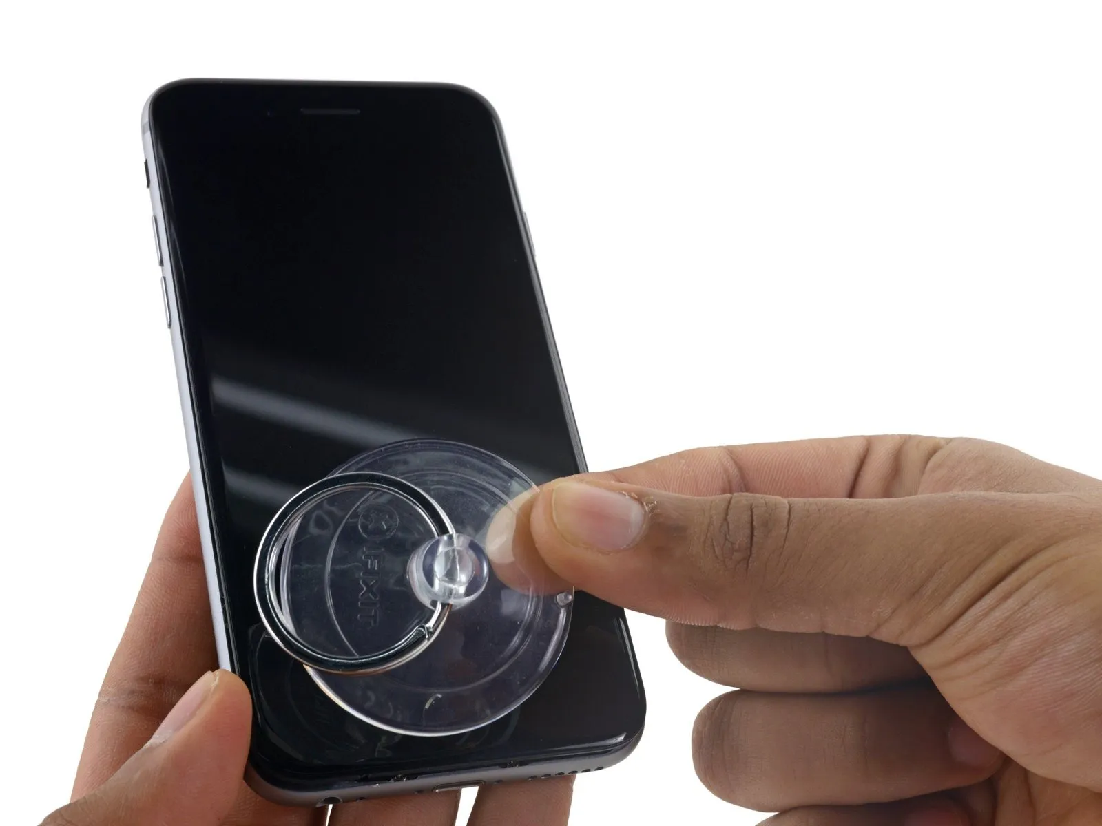
- Rotate the handle fully, completing a 360-degree turn, observing for the initial expansion of the cups.
- Maintain parallel positioning of the suction cups; should misalignment occur, gently release the suction cups' hold and reposition the arms.
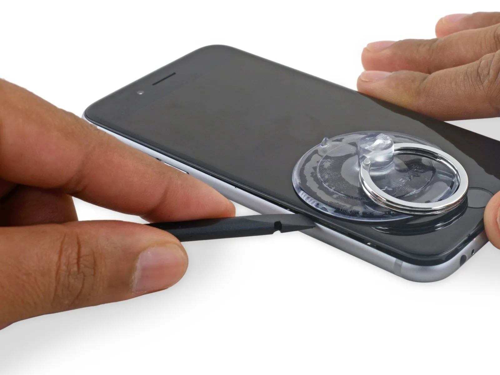
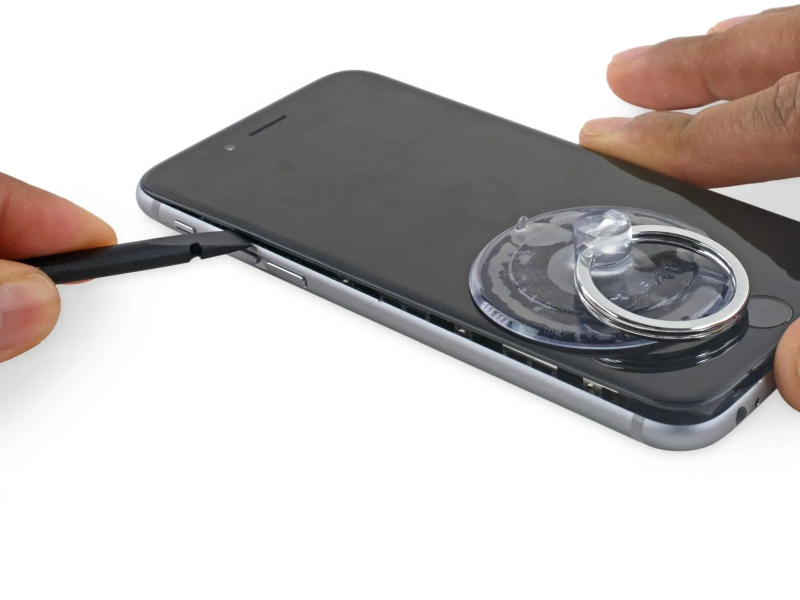
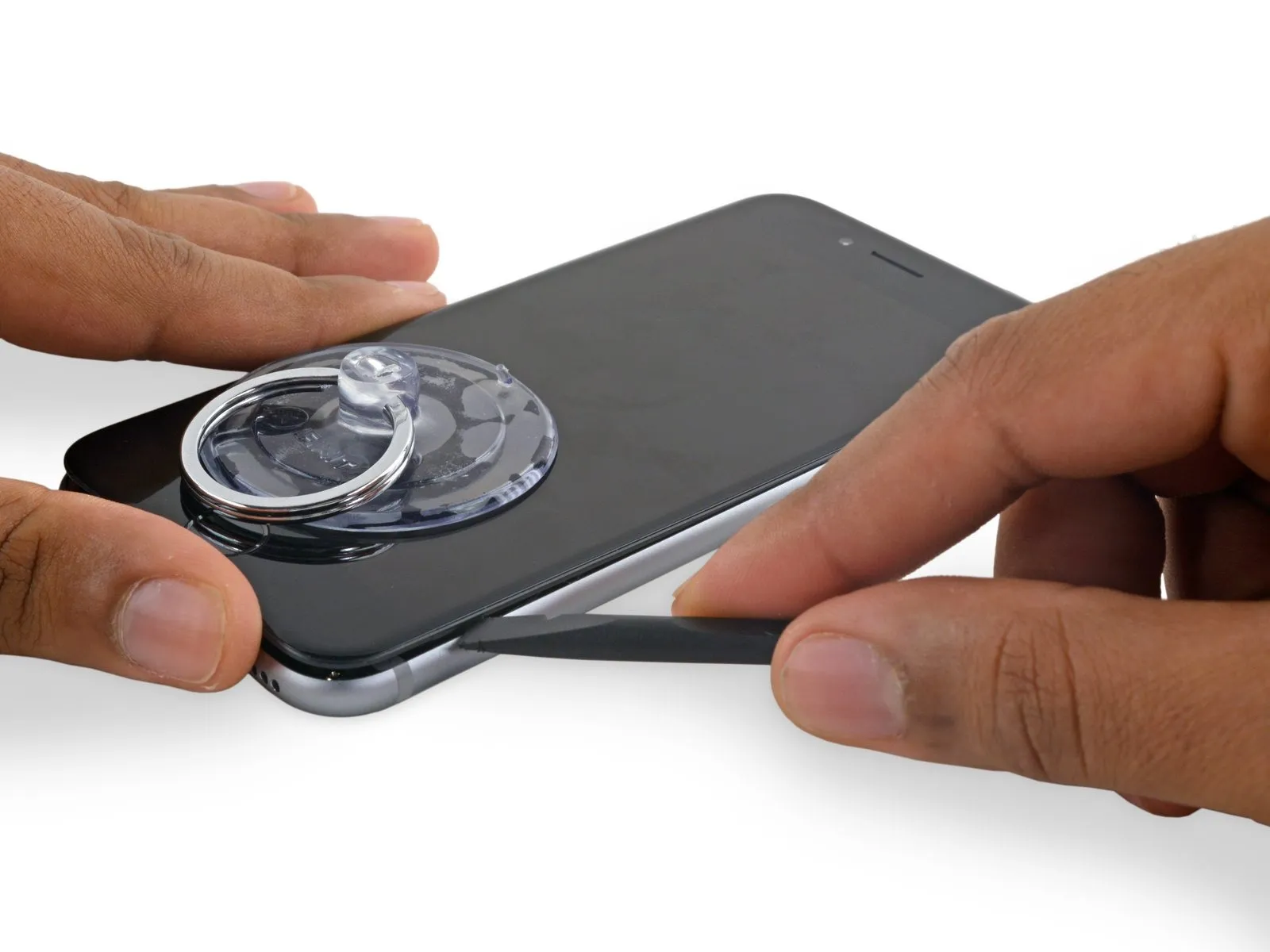
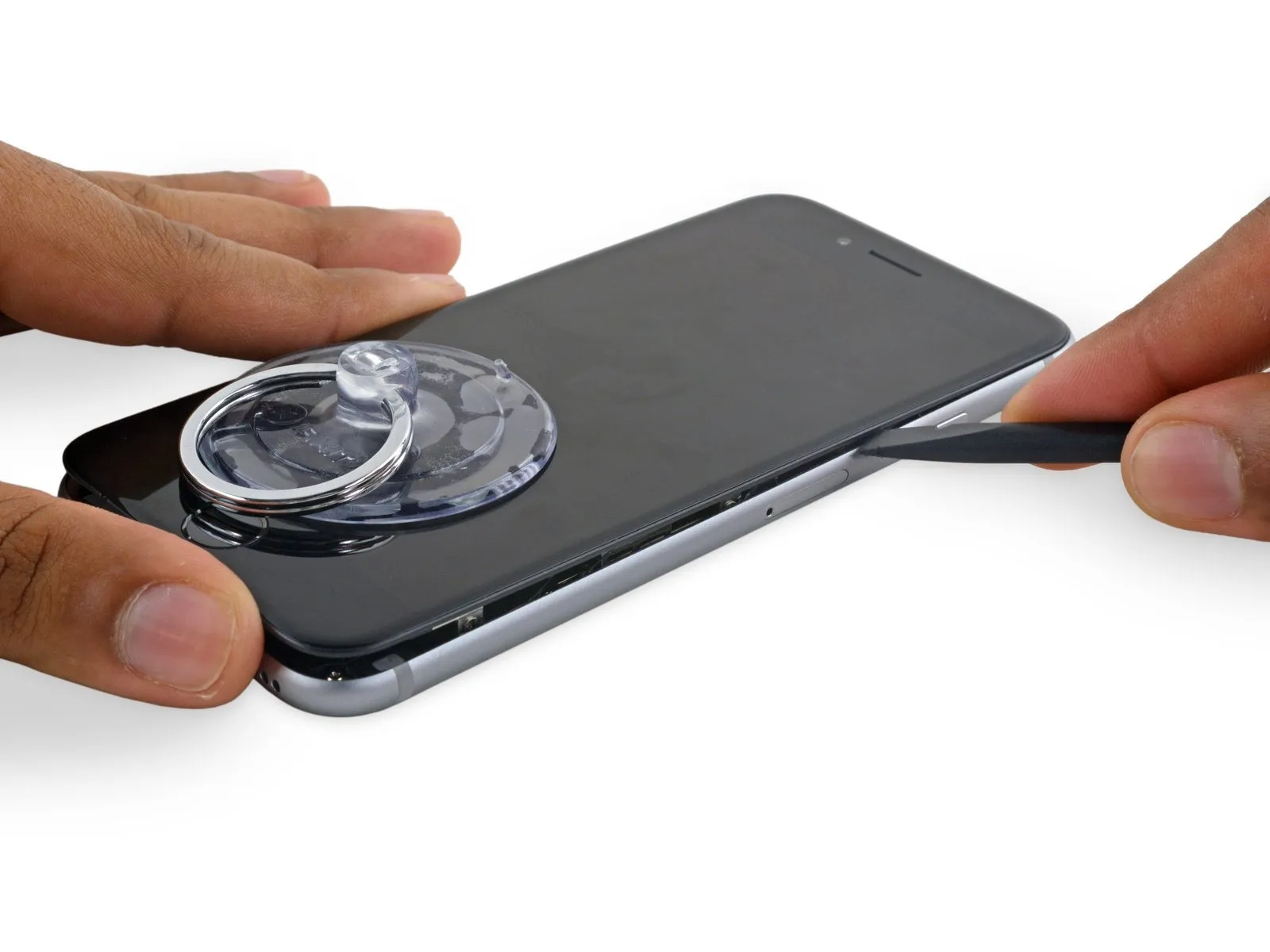
- Once sufficient separation is achieved by the Anti-Clamp tool, slide a separating tool beneath the display panel.
- To ensure adequate clearance, reposition the handle by 90 degrees.
- Allow several seconds to elapse and avoid rotating the component beyond a 90-degree movement per increment; this permits the Anti-Clamp feature to function properly and facilitates a secure connection.
Step 4 | Opening Procedure
- Carefully clamp the component, ensuring a secure grip, using a vise with a maximum pressure of 150 PSI to prevent damage during the subsequent bending process.Using the specified tools, carefully execute the procedure while strictly adhering to all safety precautions and referencing the provided dimensions and numerical values.
- Lacking an Anti-Clamp tool, proceed with the following three steps to utilize a suction handle.
- Using a hair dryer or iOpener, gently warm the iPhone's bottom edge with moderate heat for approximately one minute.
- Applying heat will loosen the adhesive that holds the display in place, simplifying the opening process.
Step 5
- To access the 6s display, carefully release the adhesive strip that runs along its edges; replacement adhesive strips should be prepared beforehand if you intend to use them, though the repair can be performed without replacement, with no expected impact on device operation.
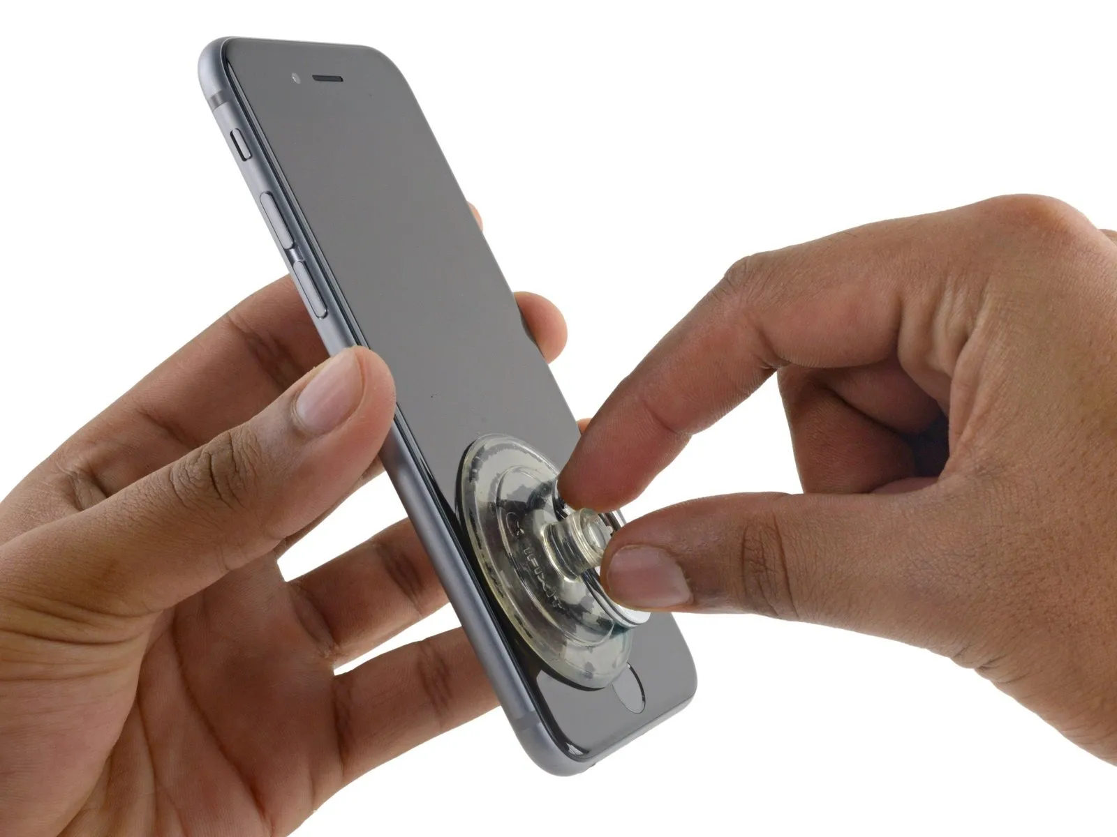
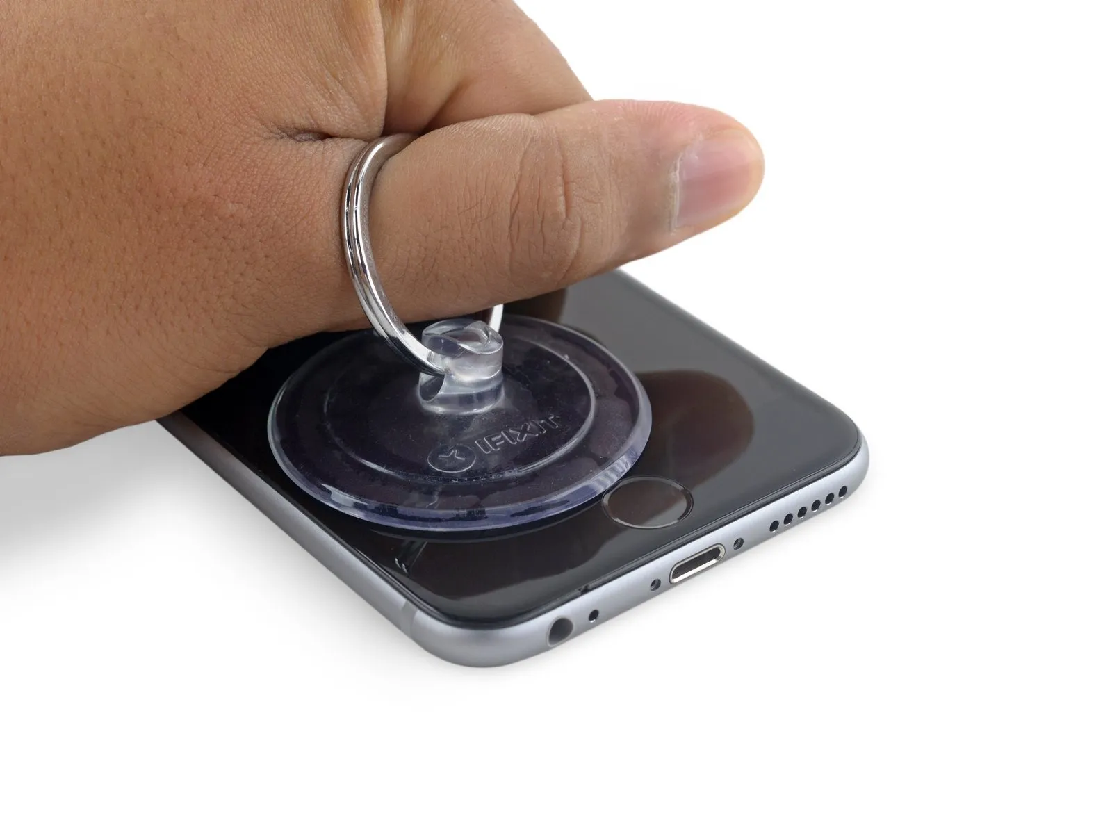
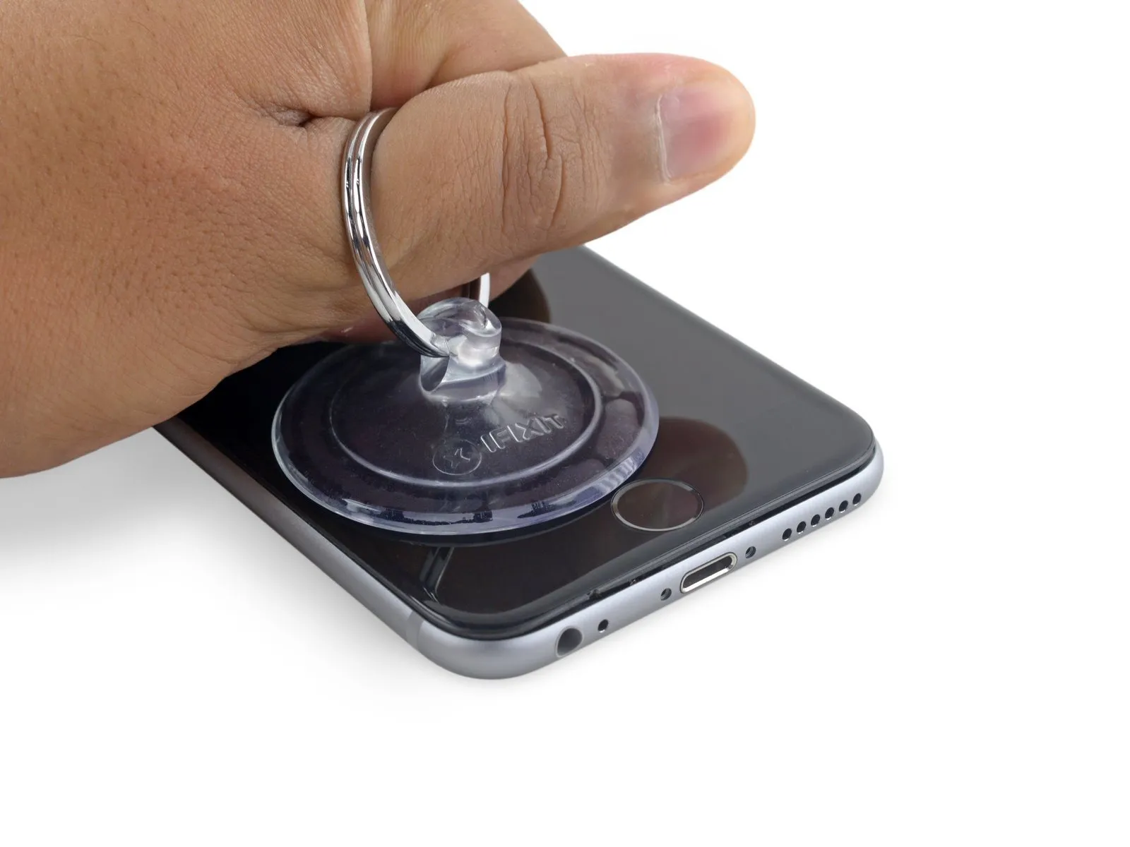
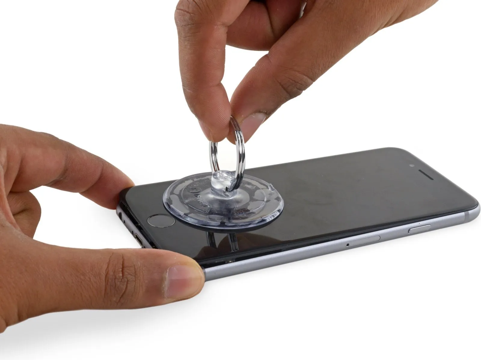
- Using a suction cup, secure its surface to the display assembly's lower-left corner.
- Avoid positioning the suction cup directly on the home button.
- To facilitate suction cup attachment when the display has severe cracking, apply a sheet of clear packing tape across the damaged area; as an alternative, a robust adhesive tape can be used in place of the suction cup. As a last resort, secure the suction cup directly to the fractured screen using superglue.
Step 6
- Apply steady, even force to lift the suction cup, generating a small separation between the front panel and the rear case.
- Exercise caution and use steady, even pressure when installing the display assembly, as it requires a snug fit and is secured with adhesive.
- To avoid display assembly damage, use minimal force when separating it from the rear case; the goal is to establish a narrow separation.
- To ease separation of the display from the frame, apply warmth to the front surface of the iPhone with an iOpener, hair dryer, or heat gun until the exterior reaches a temperature that is uncomfortably warm to the touch. This process loosens the adhesive that holds the display's perimeter in place.
Step 7
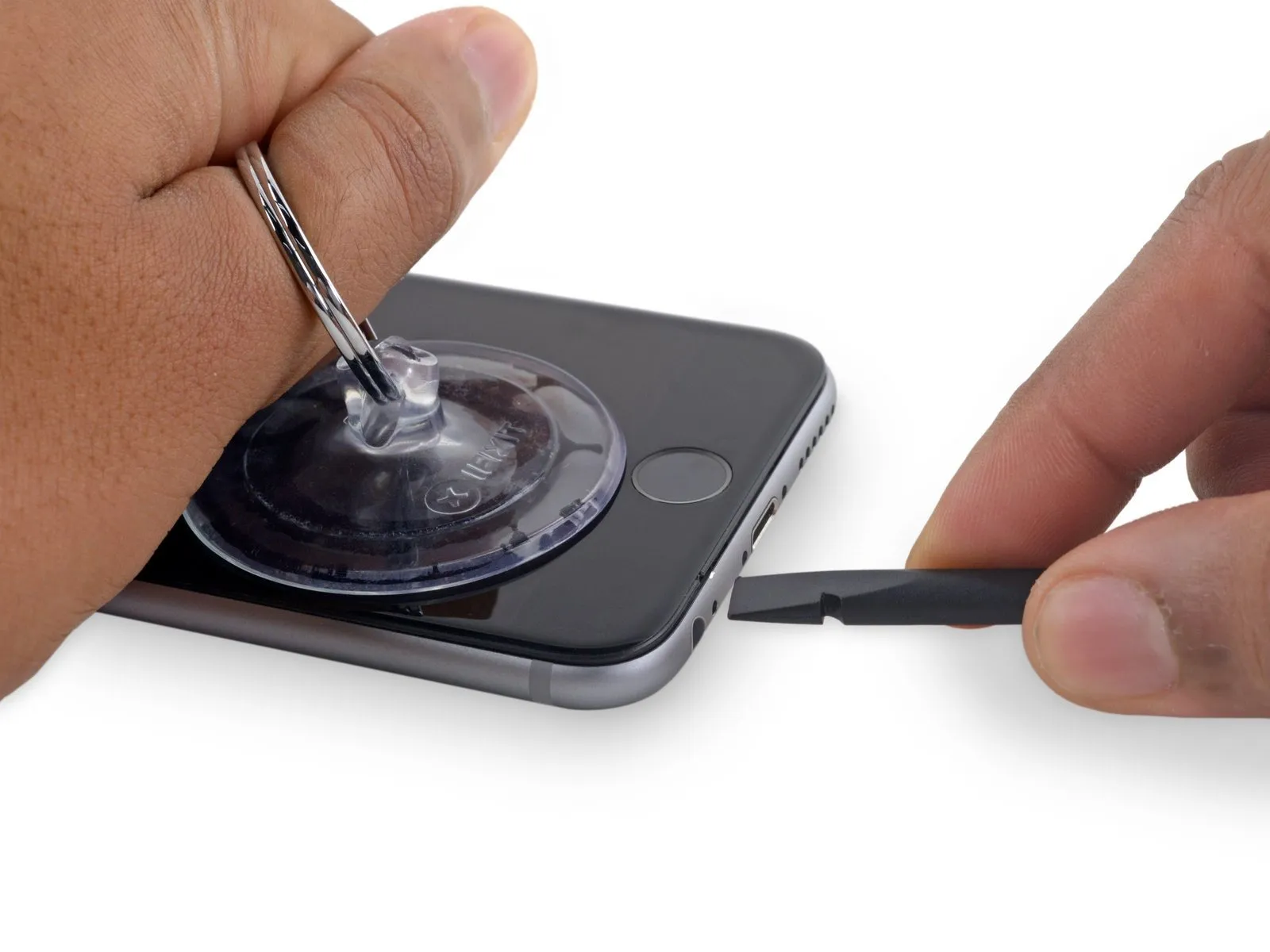
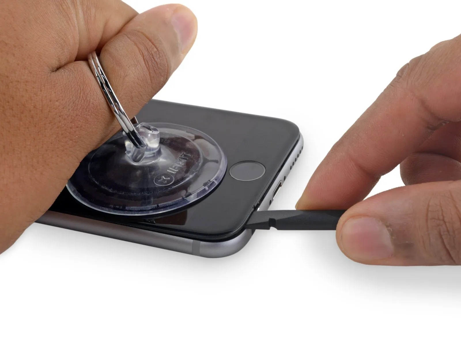
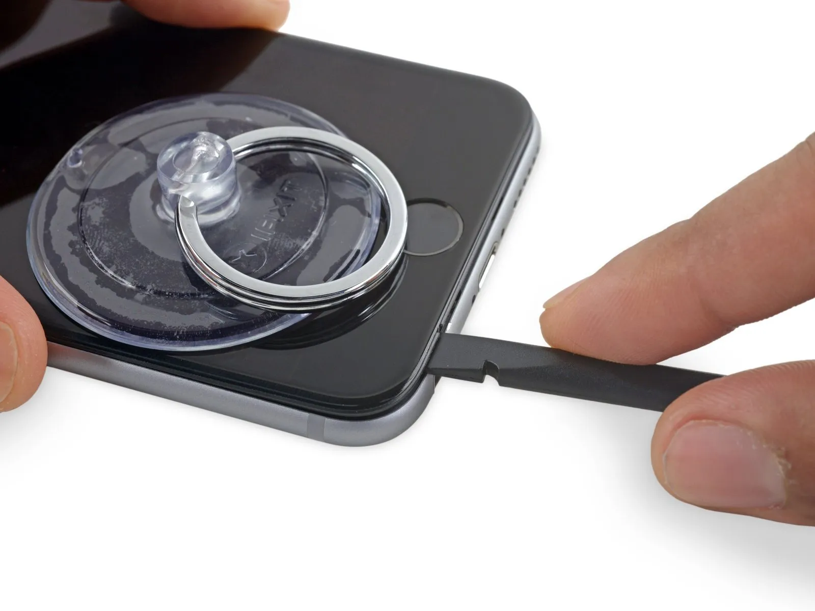
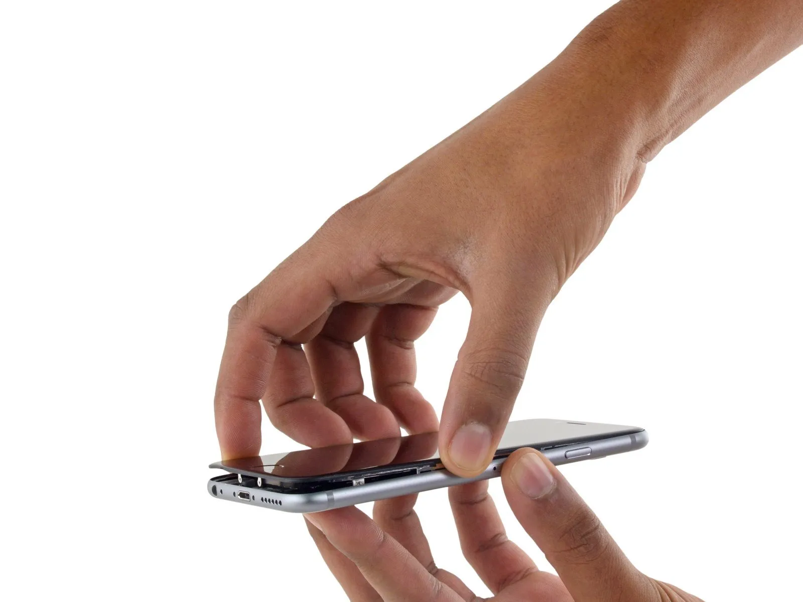
- Carefully start separating the phone's casing by inserting a prying tool into the indentation located on the bottom surface of the display, directly over the headphone jack.
- Using a spudger, insert its flat side into the separation between the display and the back cover, positioning the insertion point immediately over the headphone jack.
Step 8
- Using a spudger, gently increase the separation between the front panel assembly and the phone's main body.
Step 9
- Using the tool's straight edge, carefully slide it into the designated space.Use a plastic pry tool, often referred to as a spudger.Locate the component on the device's left lateral surface, positioned in the space separating the display assembly and the rear case.
- Carefully move theUse a plastic pry tool, often referred to as a spudger, to gently separate components.Carefully lift the device's side to release the adhesive bond and disengage the retaining clips.
Step 10
- Carefully detach the component, ensuring no damage occurs.Use a spudger.Carefully align the component with its original position along the lower edge of the device, the area previously accessed by separating the housing.
- Carefully move theUse a plastic pry tool, often referred to as a spudger.Locate the edge of the device on its right side, following the lower boundary.
Step 11
- Carefully move theUse a plastic pry tool, often referred to as a spudger.Proceed along the right edge, carefully releasing the adhesive bond and disengaging the display clips from their securing points on the iPhone.
Step 12

- Employ the 3/8-inch socket wrench to securely tighten the retaining bolt to a torque of 15 Nm, ensuring careful attention to the warning regarding potential pinch points during operation.Employ a vacuum-creating device to secure the component.Carefully separate the display assembly from the device housing by releasing the remaining adhesive bond.
- To prevent damage to the three cables securing the display at the top, limit its opening angle to a maximum of 90 degrees; exceeding this could cause them to tear.
Step 13
Step 14
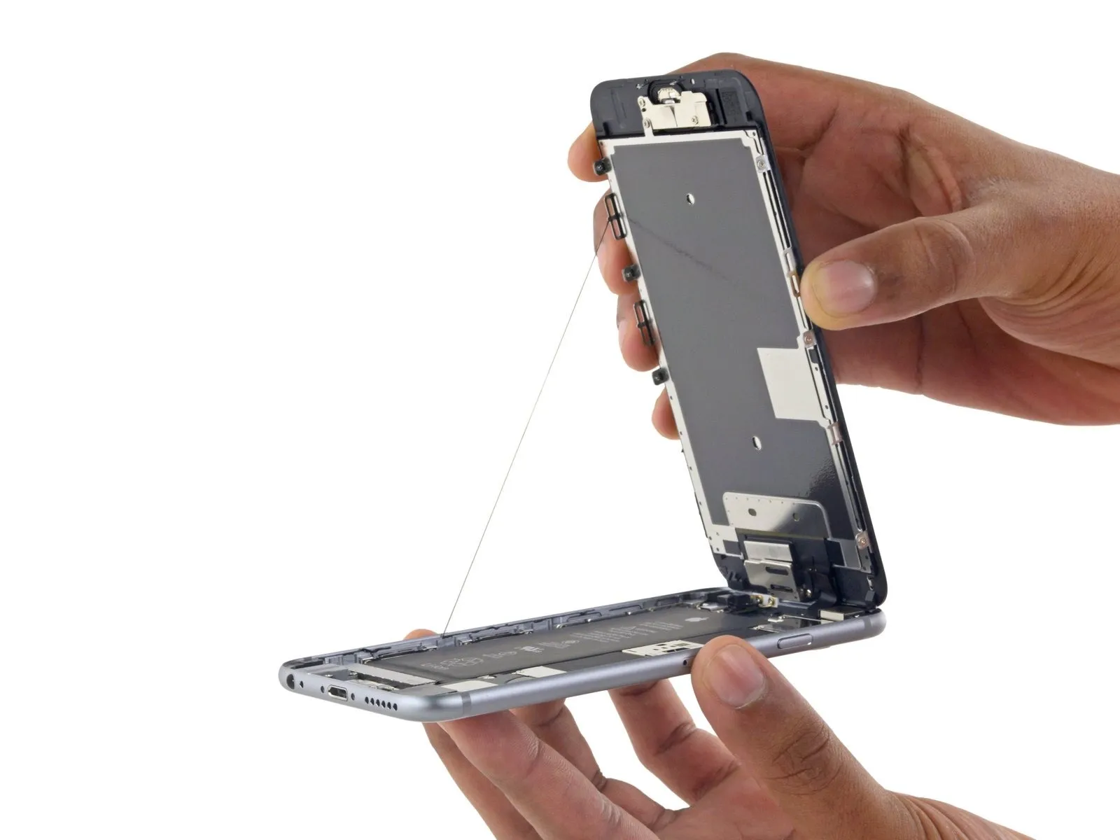
- Employing a careful grip on the display assembly, raise it to separate the phone, utilizing the front panel's upper clips as a pivot point.
- Carefully position the display at a roughly 90-degree angle, then secure it in an upright position using a support to allow for hands-free access during the repair process.
- To avoid stressing the display's wiring during the repair process, secure it with a rubber band.
- As a temporary measure, an unused, sealed canned drink can provide support for the display.
- If you intend to renew the adhesive sealant along the display's perimeter during reassembly, stop at this point.
- To ensure correct reassembly, guide the camera-side edge of the screen body beneath the main body's edge. Position the screen frame's hooks beneath the main body's rim, then gently press toward the camera end to facilitate cover closure and secure the clip.
- Ensure these clasps, which function as a substitute for a hinge, are positioned correctly beneath the phone's outer frame edge. This placement allows the screen to smoothly and gently return to its closed position, engaging with a snapping sound.
- To reinstall the screen, begin by applying pressure to secure the upper right corner, working downwards, followed by the upper left corner.
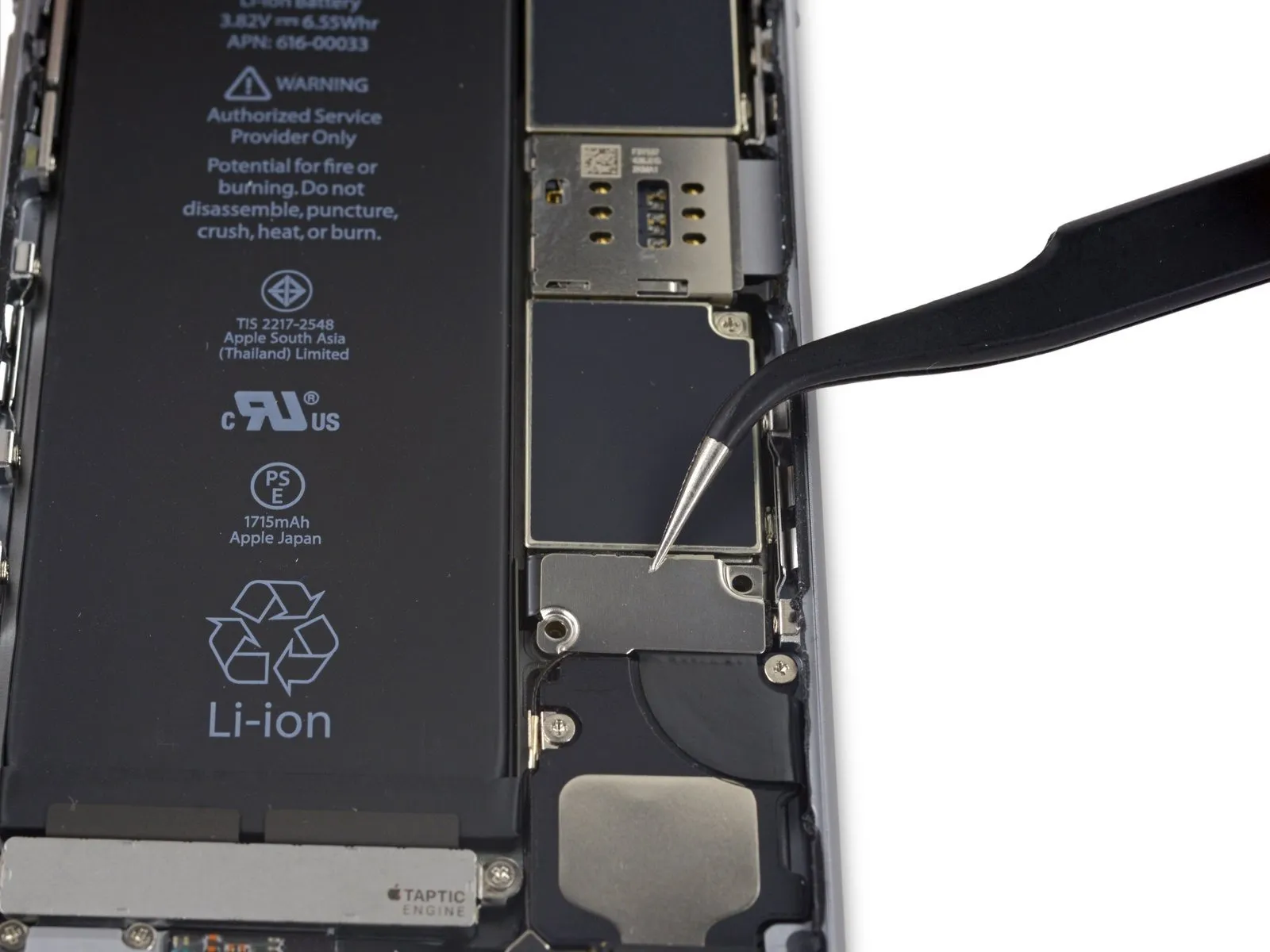
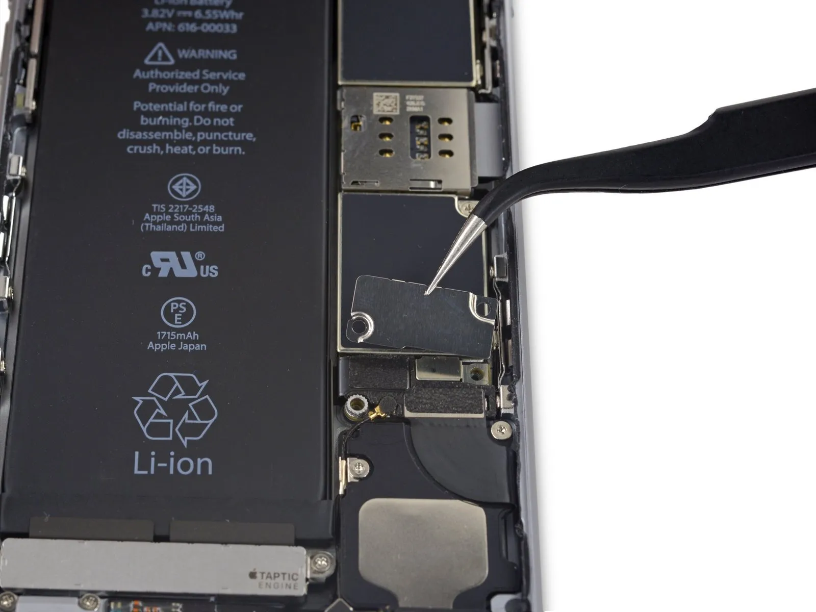
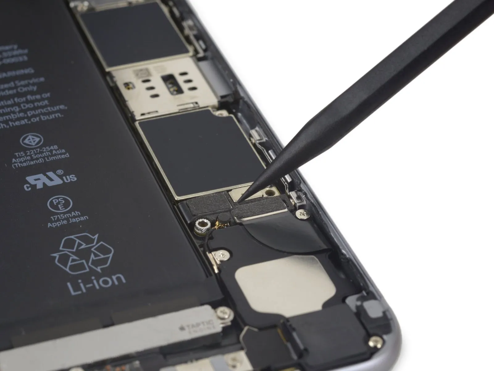
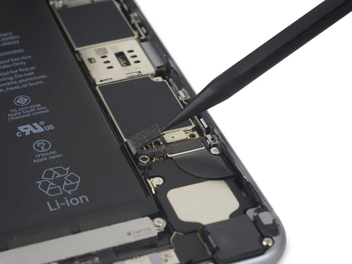
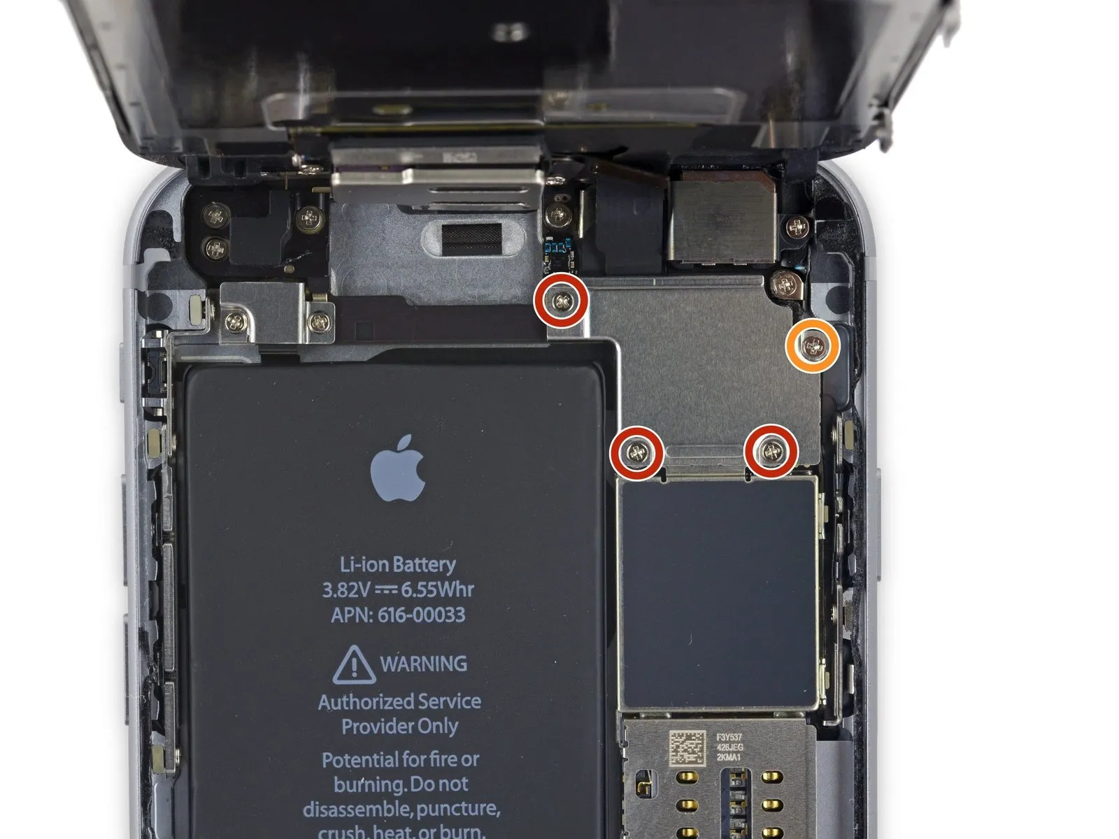
Step 15 | Battery Connector
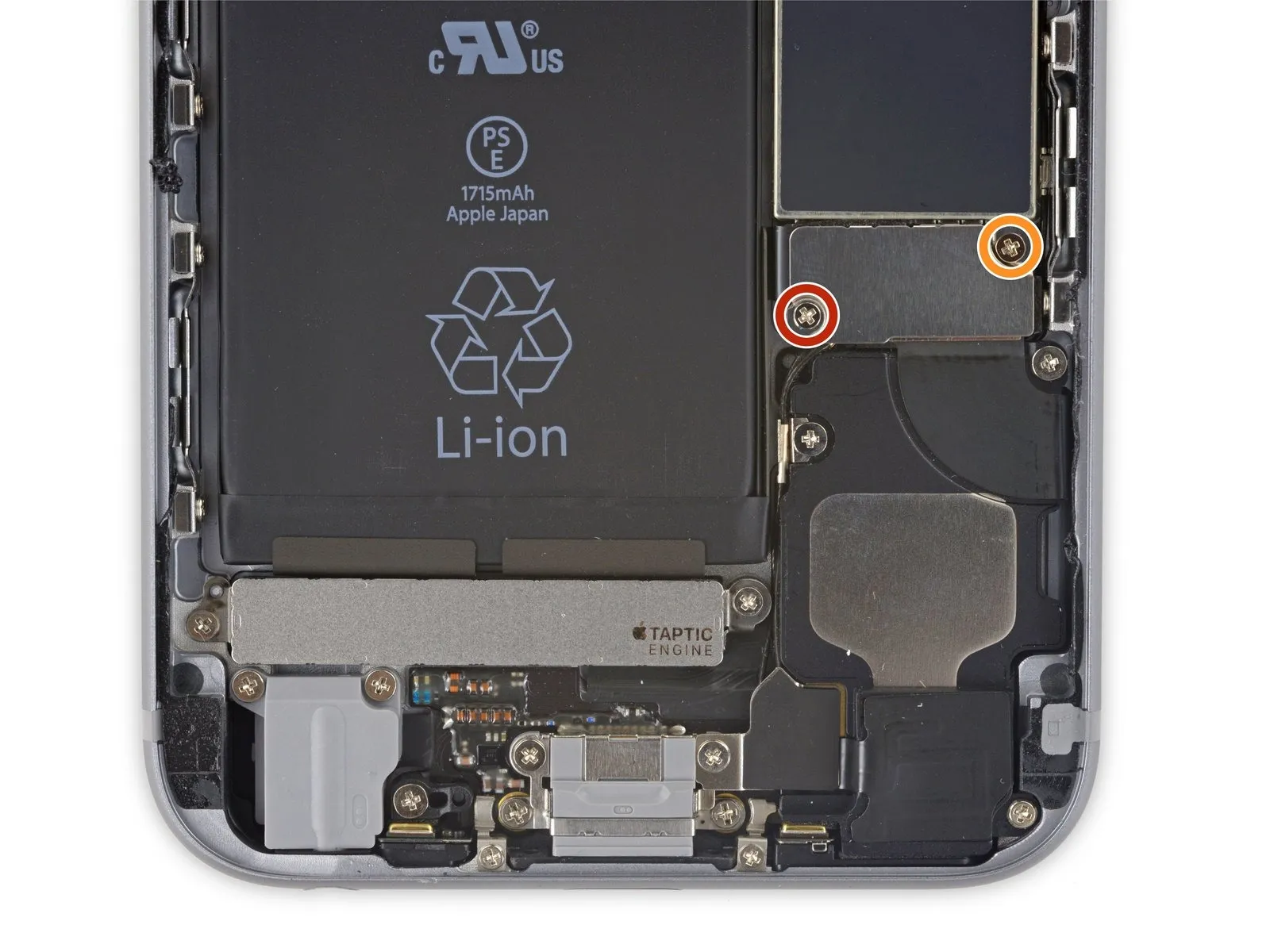
- Using a Phillips screwdriver, detach the two screws—each measuring the same length—that hold the battery connector bracket in place.
Utilize a 2.9 mm screw for installation.
Utilize a 2.2-millimeter screw for installation.
Step 16
Step 17

Step 18
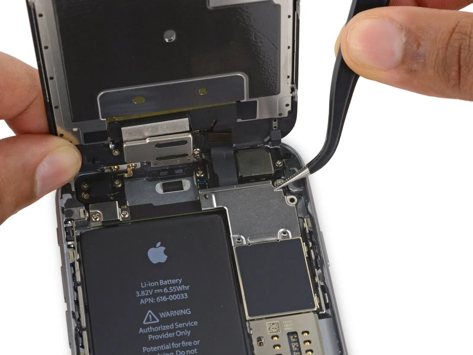
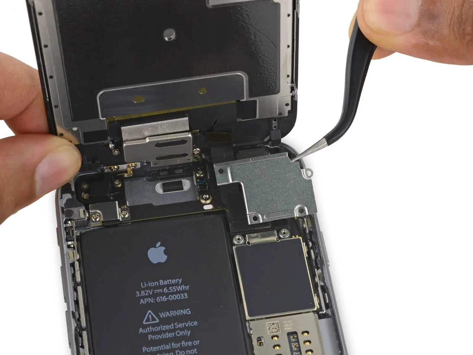
Step 19 | Unfasten the display cable bracket
- Carefully detach the quantity of four.Use a Phillips head screwdriver.Use a 3mm hex key to tighten the display cable bracket's screws to a torque of 4.0 in-lbs, ensuring the cable remains properly positioned and avoiding damage.
- A quantity of three is required.Use screws with a diameter of 1.2 millimeters.
- Begin the process with the number one.Use a 2.8-millimeter screw.
Step 20
Step 21
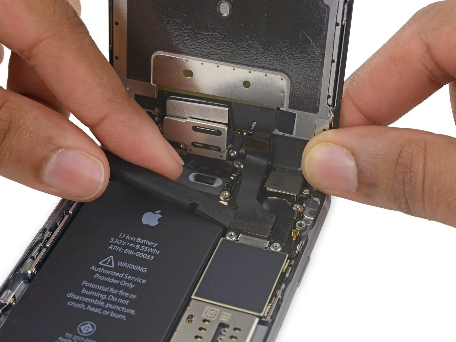
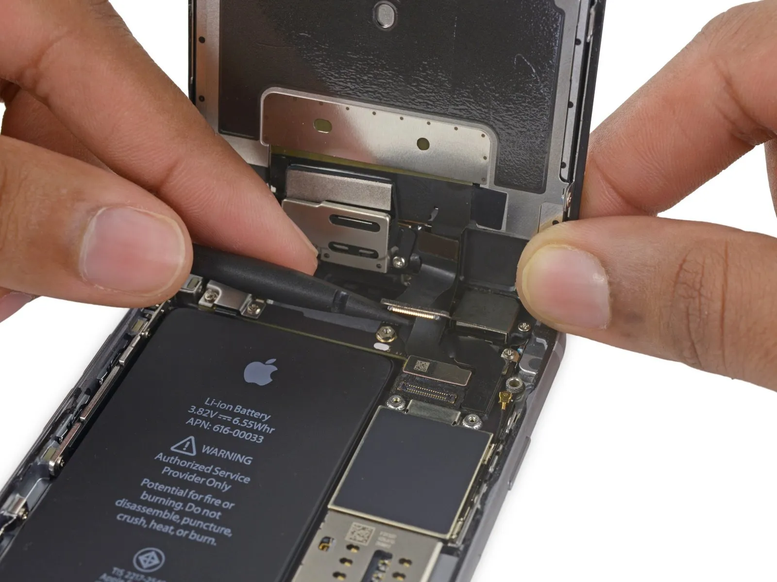
- Employ a 3/8-inch socket wrench to loosen the retaining bolt, ensuring you maintain a firm grip and wear safety glasses to protect against potential debris; then, carefully detach the component.Use a plastic pry tool to gently separate.Ensure the surface is free from any contaminants.Use a fingernail.Using a prying tool, carefully separate the front camera flex cable from its connector on the logic board by applying upward force.
Step 22
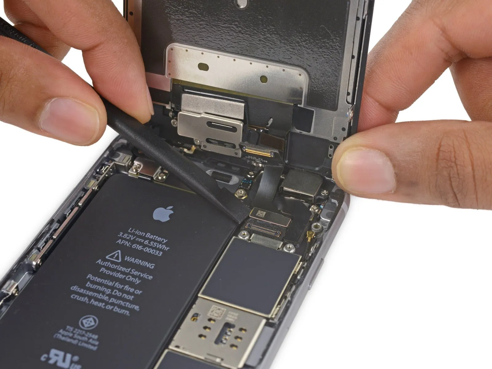
- Using a prying tool, carefully lift the digitizer cable vertically away from its connector on the logic board.
- To ensure proper alignment and prevent damage, apply pressure to opposing ends of the digitizer cable connector during reconnection; avoid central pressure, as this may warp the component.Inspect the display assembly for cracks, delamination, or other physical defects affecting the touch-sensitive layer, ensuring measurements remain within tolerance (typically no greater than 1mm deviation from factory specifications) and noting any damage to the digitizer itself..
Step 23
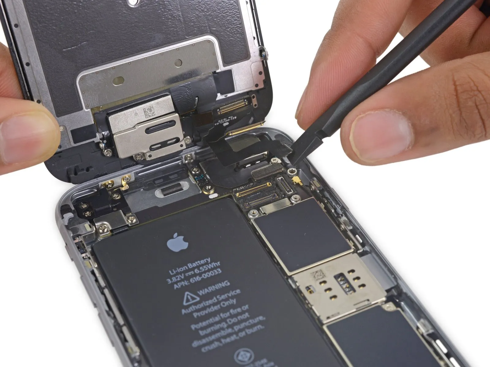
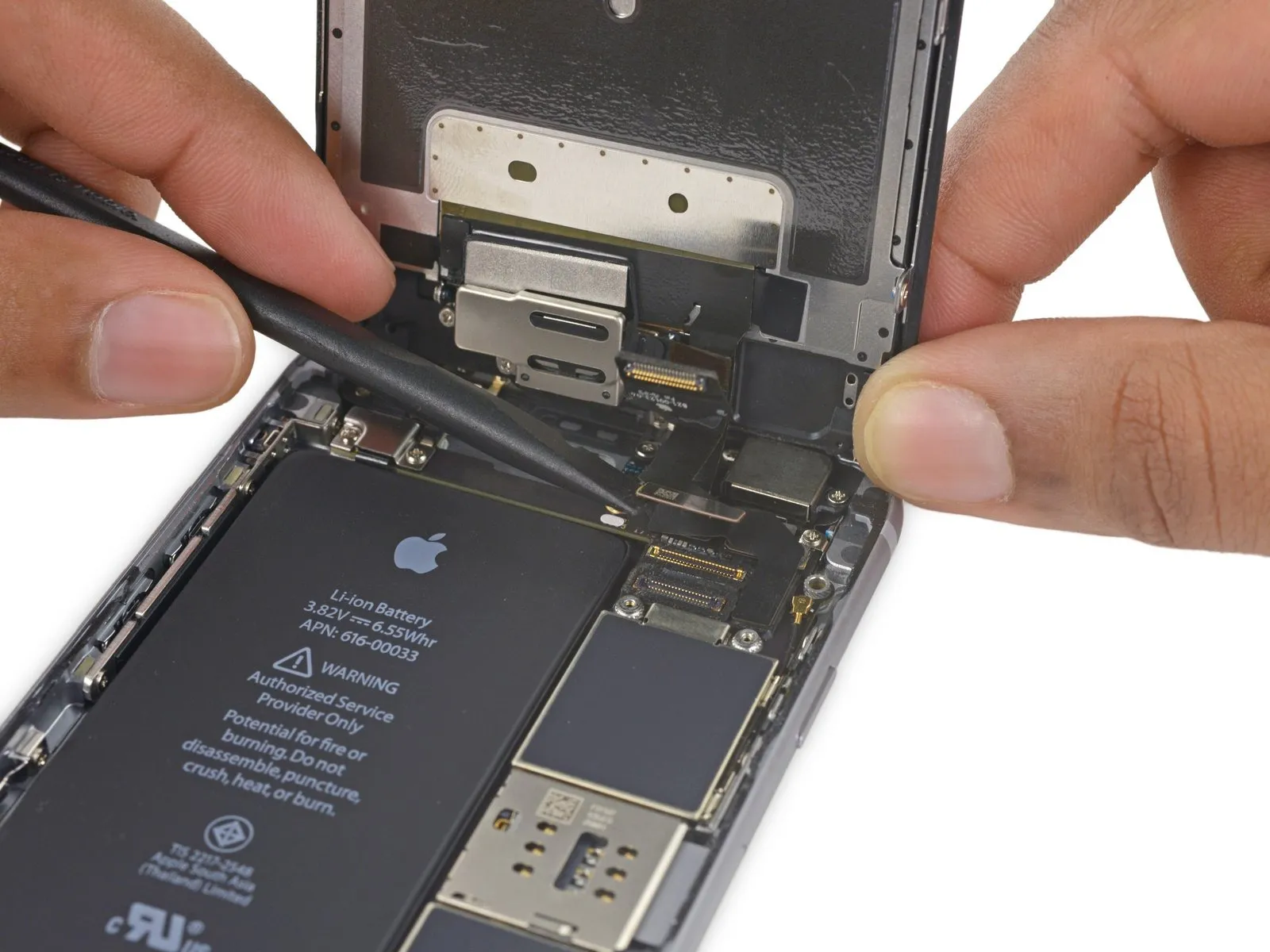
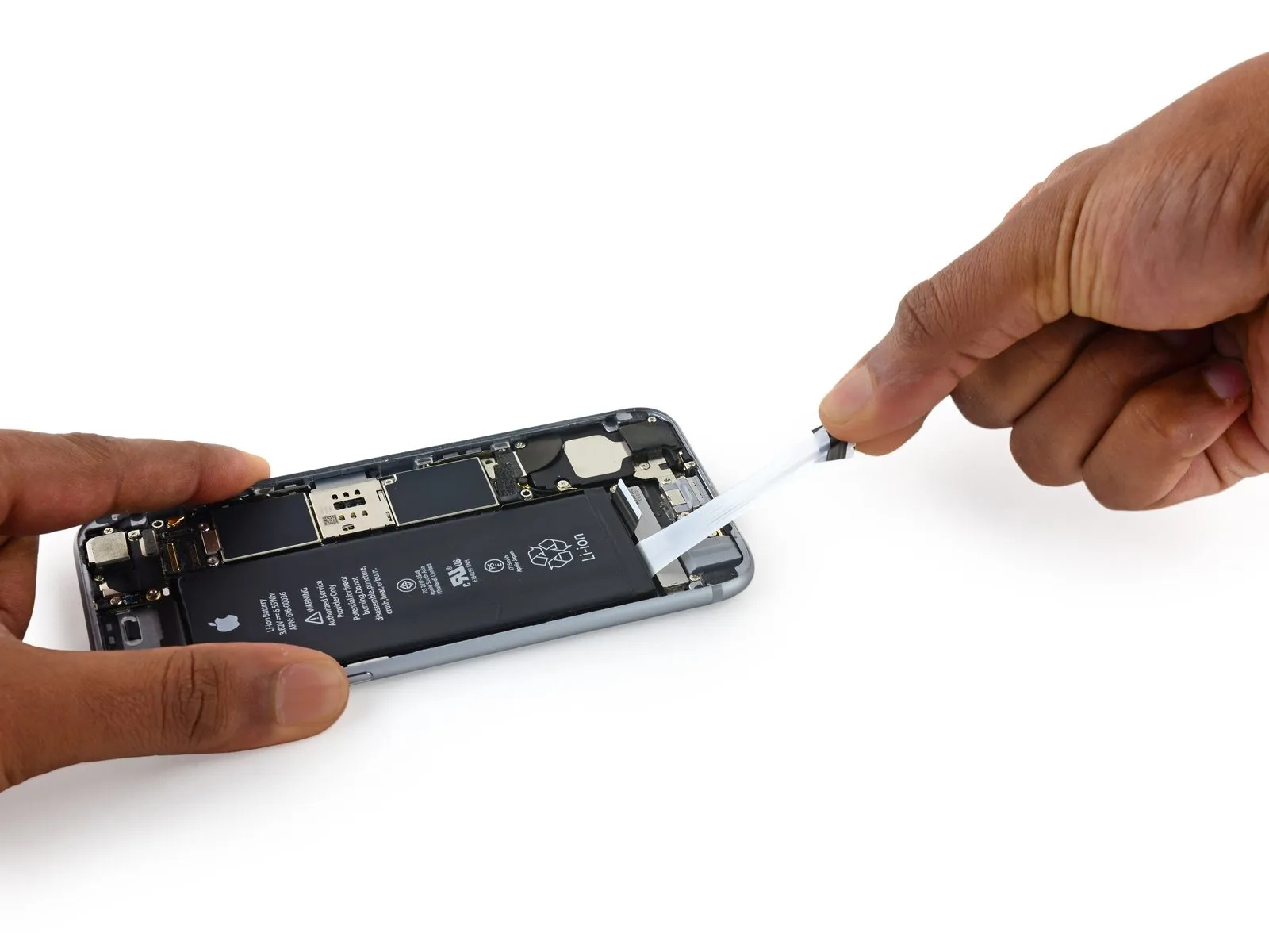
- Prior to either detaching or reattaching the cable in this procedure, ensure the battery is disconnected.
- Using a prying motion, carefully separate the display cable from its connection on the logic board, ensuring it moves vertically.
Step 24
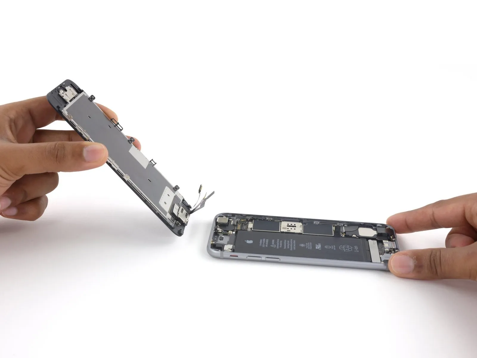
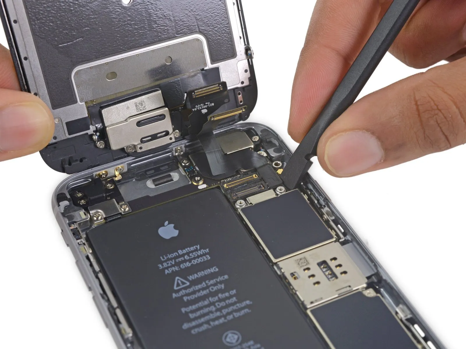
- Carefully detach the display assembly, ensuring no damage occurs.
- If you intend to substitute fresh adhesive along the display's perimeter during reassembly, stop at this point.
Step 25 | Battery
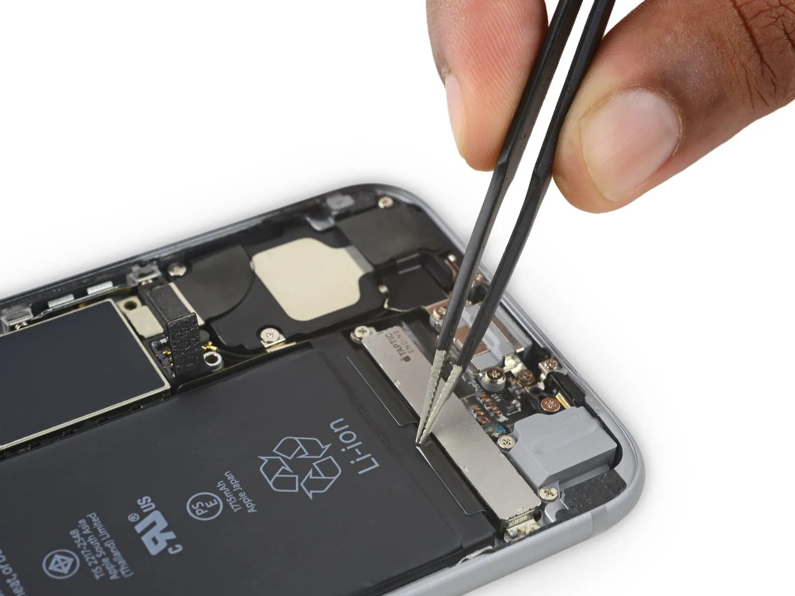
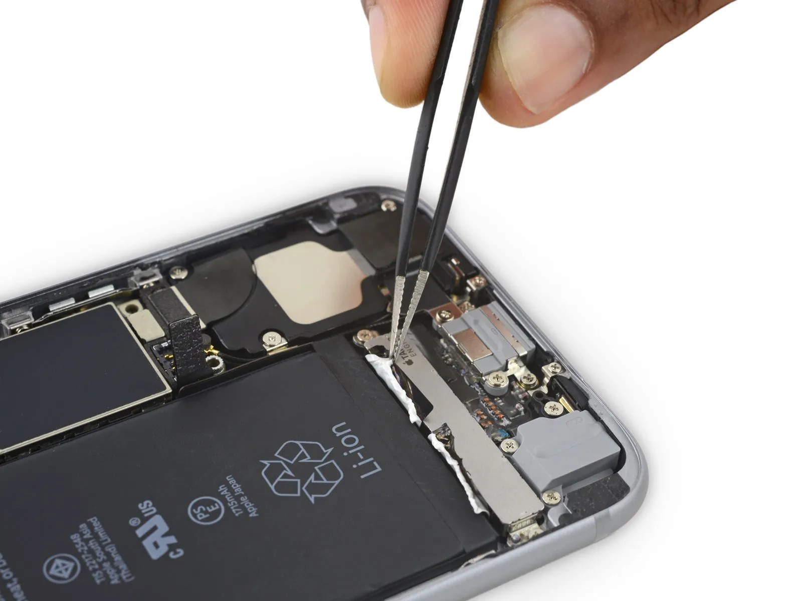
- Carefully lift the ends of the two adhesive strips, located along the battery's lower edge, using tweezers.
Employ either your fingertips or non-pointed tweezers to manipulate components, exercising caution in the vicinity of the lithium-ion battery, as its compromise through puncture may result in the release of hazardous substances and/or ignition. - For improved access to the adhesive strips, the Taptic Engine can be detached at this stage if desired.
Step 26
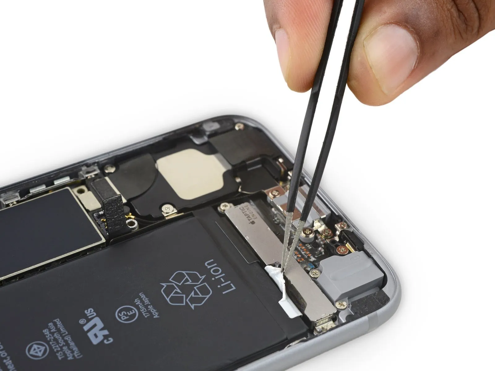
- To prevent the strips from adhering and tearing, ensure they remain smooth and free of creases throughout this step.
- Gently separate a battery adhesive strip from the battery surface, directing its movement downwards within the iPhone's interior.
Exercise caution during removal to prevent damage to the adhesive strip by ensuring it does not contact the battery or any components located beneath it.
Apply consistent, even force to the strip, ensuring it remains taut as it disengages from the space between the battery and the rear case; to optimize the process, limit the pulling angle to 60 degrees or less.
Expect the strip to extend significantly, potentially several times its initial length; if needed, reposition your grip closer to the battery to maintain tension while pulling.
Step 27
- Perform the same procedure on the remaining strip.
To prevent the battery from being ejected unexpectedly during removal, maintain pressure on it while detaching the second strip.
Having detached the two adhesive strips without issue, proceed directly to step 29.
To reattach the battery when the underlying adhesive strips are damaged and inaccessible, carefully introduce a small amount of isopropyl alcohol—ensure it's at least 90% concentration—beneath the battery's edge, specifically targeting the location of the detached adhesive strip(s).
Allow approximately one minute for the alcohol to dissolve the adhesive securing the battery, then carefully pry the battery loose using the spudger's flat edge.
Avoid using excessive force when dislodging the battery.To assist separation, add additional alcohol as necessary to dissolve the adhesive; however, avoid using the pry tool to damage or compromise the battery's structural integrity.
Avoid using the spudger to access any space located between the volume down (-) button and the battery's upper boundary.Care should be taken to avoid damaging the volume control cable, which is located beneath, and prying on the logic board, as this could harm the device.
Step 28 | Alternative methods to unstick the battery from the case
- Should the adhesive strips detach cleanly, proceed to the subsequent step; if not, carefully separate the battery from the rear case using prying tools.
- To loosen the adhesive securing the rear case, use an iOpener, positioning it over the battery area, or alternatively, apply heat with a heat gun or hair dryer.
- Carefully raise the battery from its position using a plastic opening tool, applying gentle pressure.
Exposure to excessive heat presents a fire hazard due to the lithium-ion battery within the iPhone. - To detach the battery from the back cover, use dental floss or, for greater leverage, an unwound guitar string—specifically, a 0.009 E string from a 12-string guitar set—as a substitute.
- Using floss or string, carefully guide it between the upper battery and its housing, then join the ends and secure them by wrapping around a folded piece of cloth before applying consistent tension.
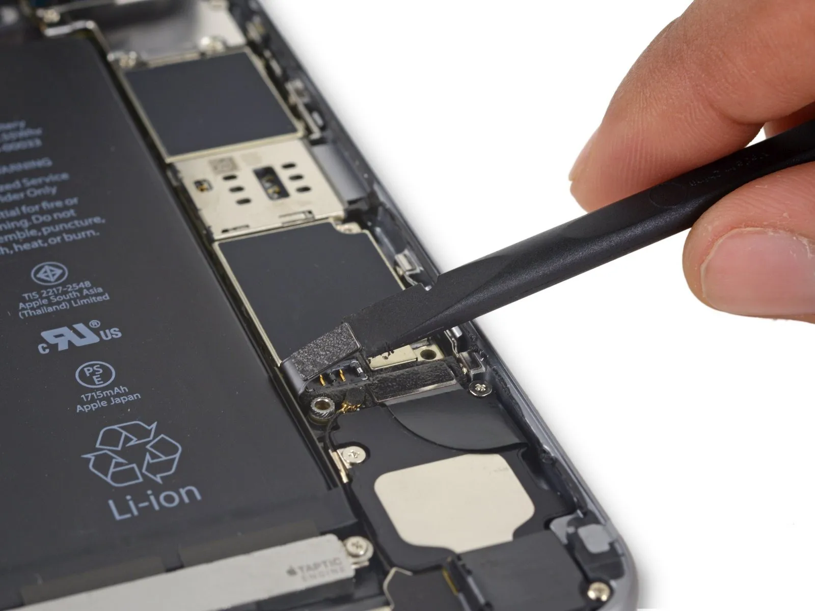
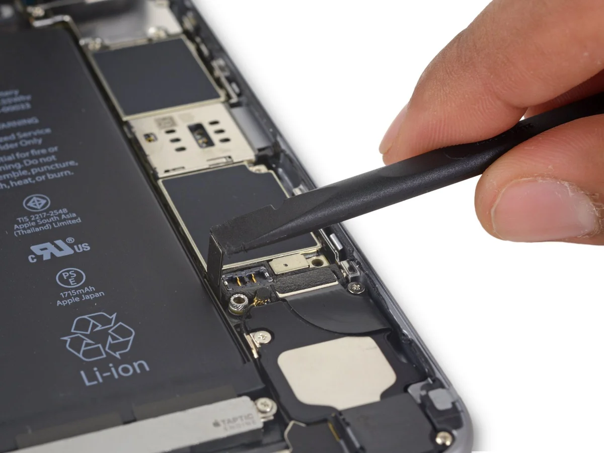
Step 29 | Battery Removal
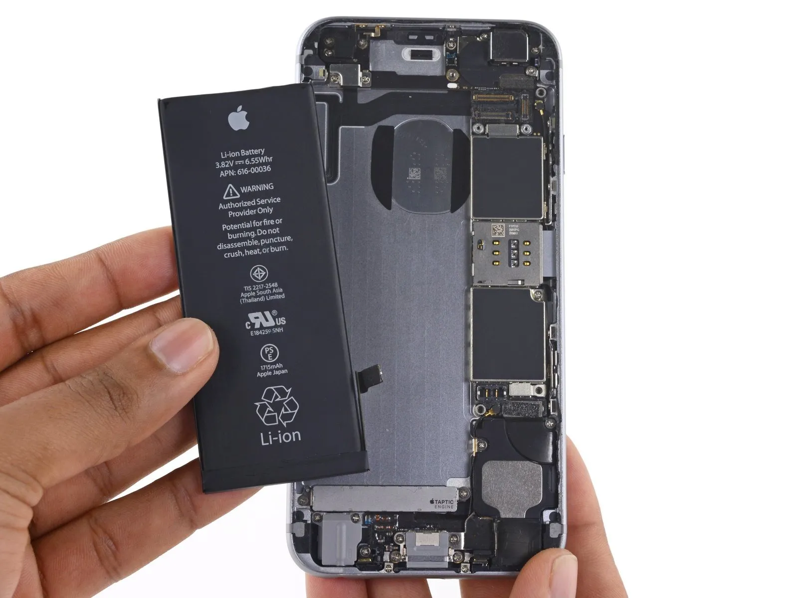
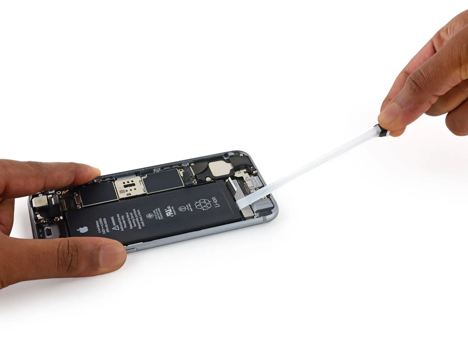
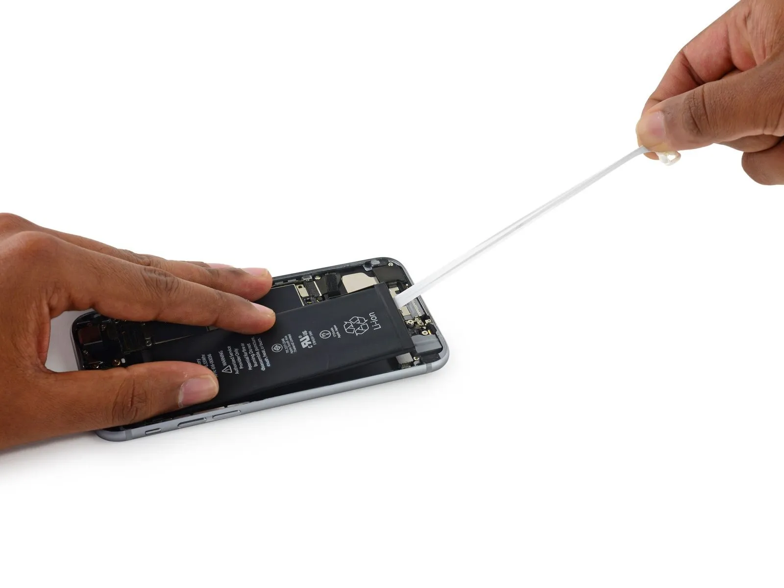
- Disconnect the power source by detaching the battery.
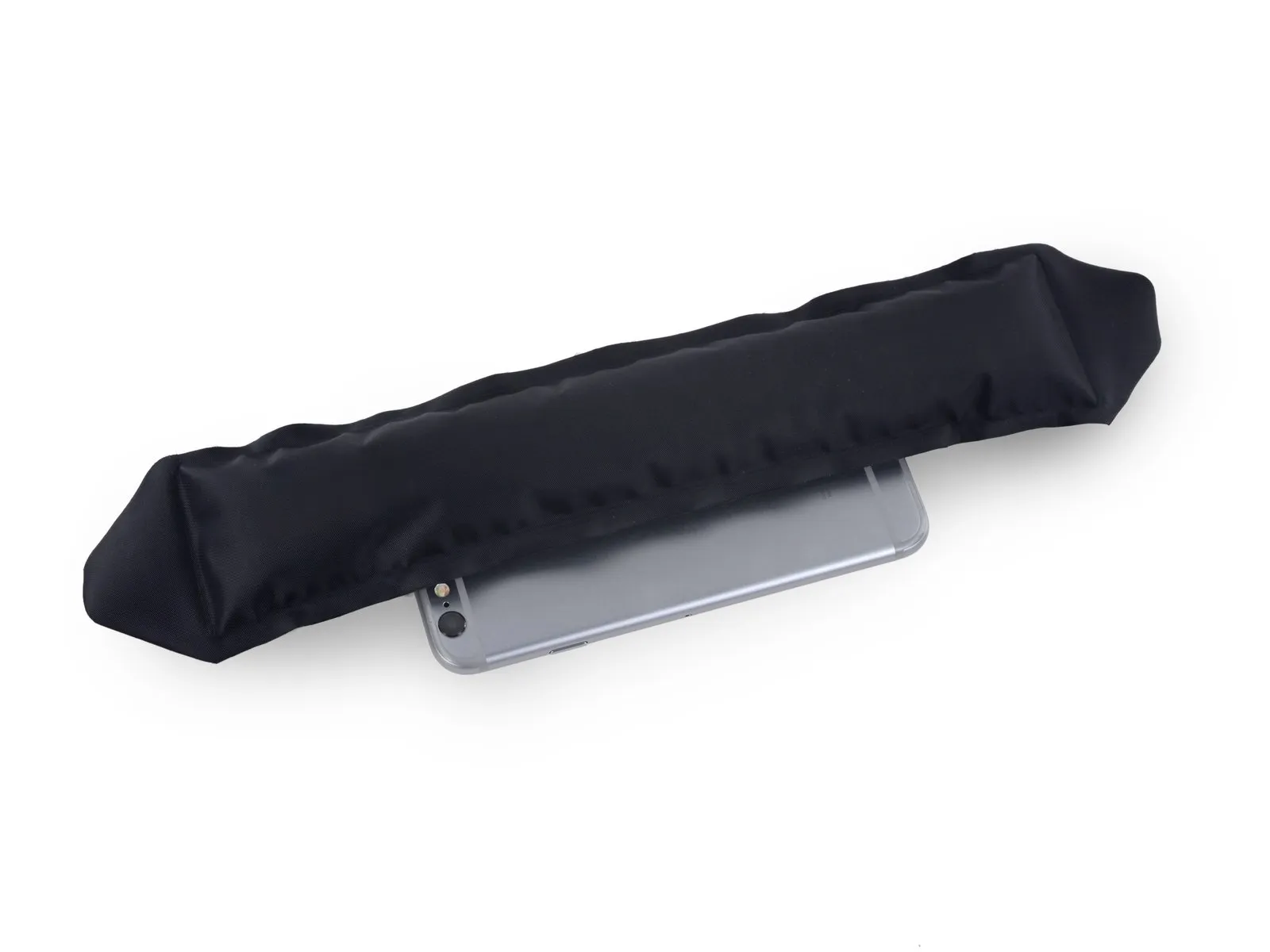
- Carefully slide the plastic protective covering off the new battery, ensuring you do not snag or damage the ribbon cable during removal.
- To prevent damage, ensure any residual alcohol solution is completely removed by wiping with a clean cloth or permitting full evaporation prior to battery replacement.
- To guarantee correct positioning within its designated space, briefly plug the battery connector back into the logic board socket prior to securing the new battery.