iPhone 6 LCD Shield Plate Replacement
This guide details the procedure for either detaching or substituting the rear metal shield covering the iPhone 6 front panel.
- This document also provides instructions for substituting these components.
Step 1 | Pentalobe Screws

To prevent a potential fire or explosion hazard from the lithium-ion battery during disassembly, ensure its charge level is reduced to less than 25% beforehand; a fully charged battery poses a significant risk of ignition if damaged.
To prevent electrical shock or damage, ensure the iPhone is completely de-energized prior to starting the repair process.
Using a Pentalobe screwdriver, detach the two screws measuring 3.6 mm in length, positioned adjacent to the Lightning connector.
To prevent electrical shock or damage, ensure the iPhone is completely de-energized prior to starting the repair process.
Using a Pentalobe screwdriver, detach the two screws measuring 3.6 mm in length, positioned adjacent to the Lightning connector.
Step 2 | Anti-Clamp instructions


To simplify the opening process, the following two steps utilize the Anti-Clamp tool, a custom design; if you do not have this tool, proceed to the steps three sections later for an alternative approach.
Refer to the accompanying guide for detailed procedures regarding the Anti-Clamp's operation.
To release the Anti-Clamp's arms, move the blue handle in a rearward direction.
Position the arms so they clear the left or right side of the iPhone, then move them into place.
Carefully place a suction cup on the front of the iPhone, close to the lower edge and directly over the home button, and another suction cup on the rear, in a similar location near the bottom edge.
Apply vacuum by pressing the cups firmly against the surface you intend to work on.
To improve the Anti-Clamp's adherence if the iPhone's exterior feels excessively smooth, apply adhesive tape to the device's surface.
Step 3


To secure the arms, advance the blue handle in its direction.
Rotate the handle fully, completing a 360-degree turn, observing for the initial signs of cup expansion.
Maintain parallel positioning of the suction cups; should misalignment occur, gently release the suction cups' hold and reposition the arms.
Once sufficient separation is achieved by the Anti-Clamp, slide a prying tool beneath the display panel.
To ensure adequate separation, reposition the handle by 90 degrees.
Allow several seconds to pass and avoid rotating the component beyond a 90-degree movement per increment; this permits the Anti-Clamp device and settling time to function effectively.
Step 4 | Manual Opening Procedure

Lacking an Anti-Clamp tool, secure the front panel with a single suction cup for lifting.
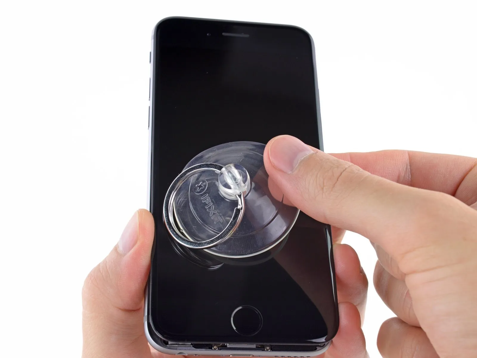
Securely affix a suction cup to the display surface, positioning it directly over the home button area.
Ensure a leakproof connection by firmly applying pressure to the cup against the screen's surface.
To facilitate suction cup attachment on a severely cracked display, apply a sheet of clear packing tape across the damage; as an alternative, a robust adhesive tape can be substituted for the suction cup. As a last resort, secure the suction cup directly to the fractured screen using superglue.
Step 5
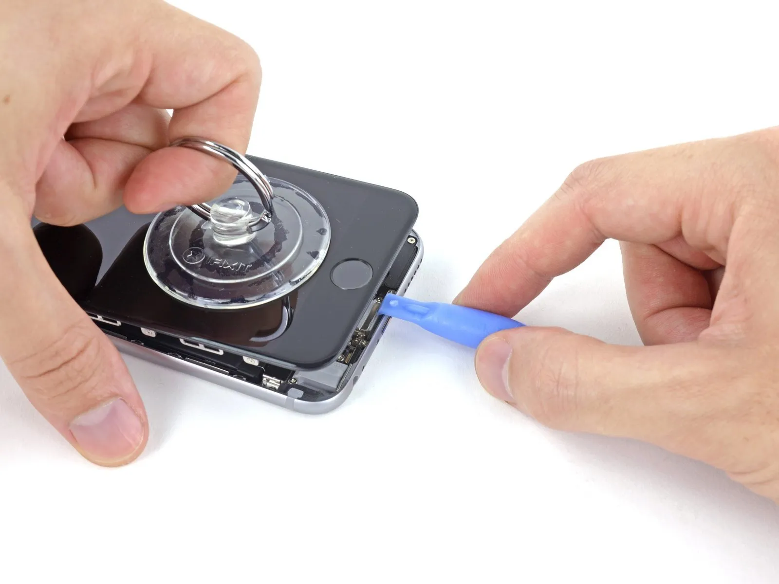
Using one hand to secure the iPhone, lift the suction cup vertically to gently create a small gap between the front panel and the device's back cover.
Exercise caution and use steady, even pressure when installing the display assembly, as its fit is considerably more snug than typical device components.
Carefully separate the rear case from the display assembly by gently levering it downwards with a plastic opening tool, maintaining upward traction on the display with the suction cup.
To release the front panel assembly from the rear case, carefully detach the retaining clips, which may require using both the suction cup and the plastic opening tool in conjunction.
Step 6

To detach the suction cup, depress the plastic projection to break the airtight seal.
Detach the display assembly's suction cup.
Detach the display assembly's suction cup.
Step 7 | Opening up the phone

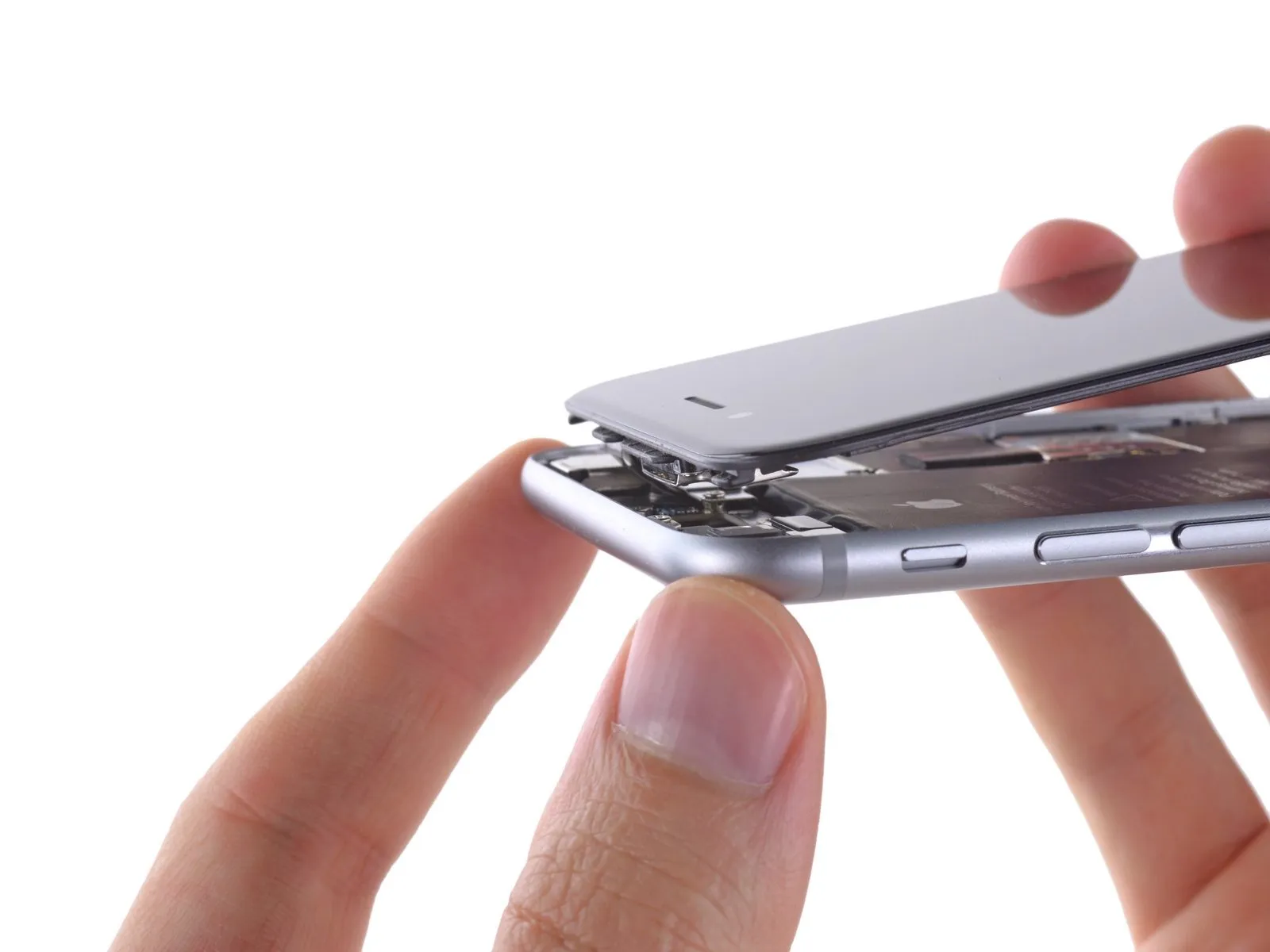
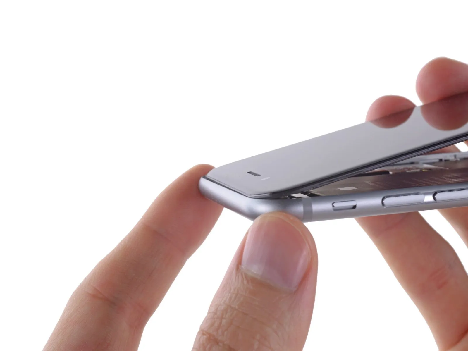
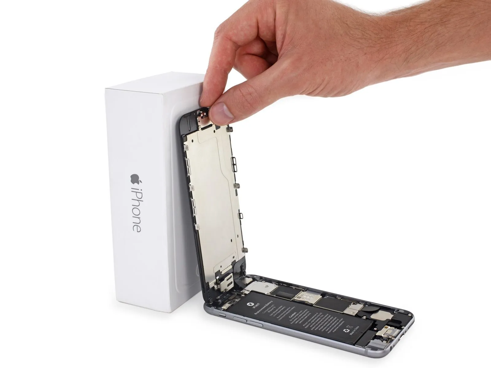
Using the phone's upper edge as a pivot point, carefully detach the front panel assembly from the rear case by gently moving the home button end outward.
Along the front panel's upper edge, multiple clips function as a partial hinge.
Ensure the clips located immediately beneath the rear case's upper border are properly positioned during reassembly, subsequently sliding the front panel upwards until its superior edge is level with the rear case's top edge.
Step 8

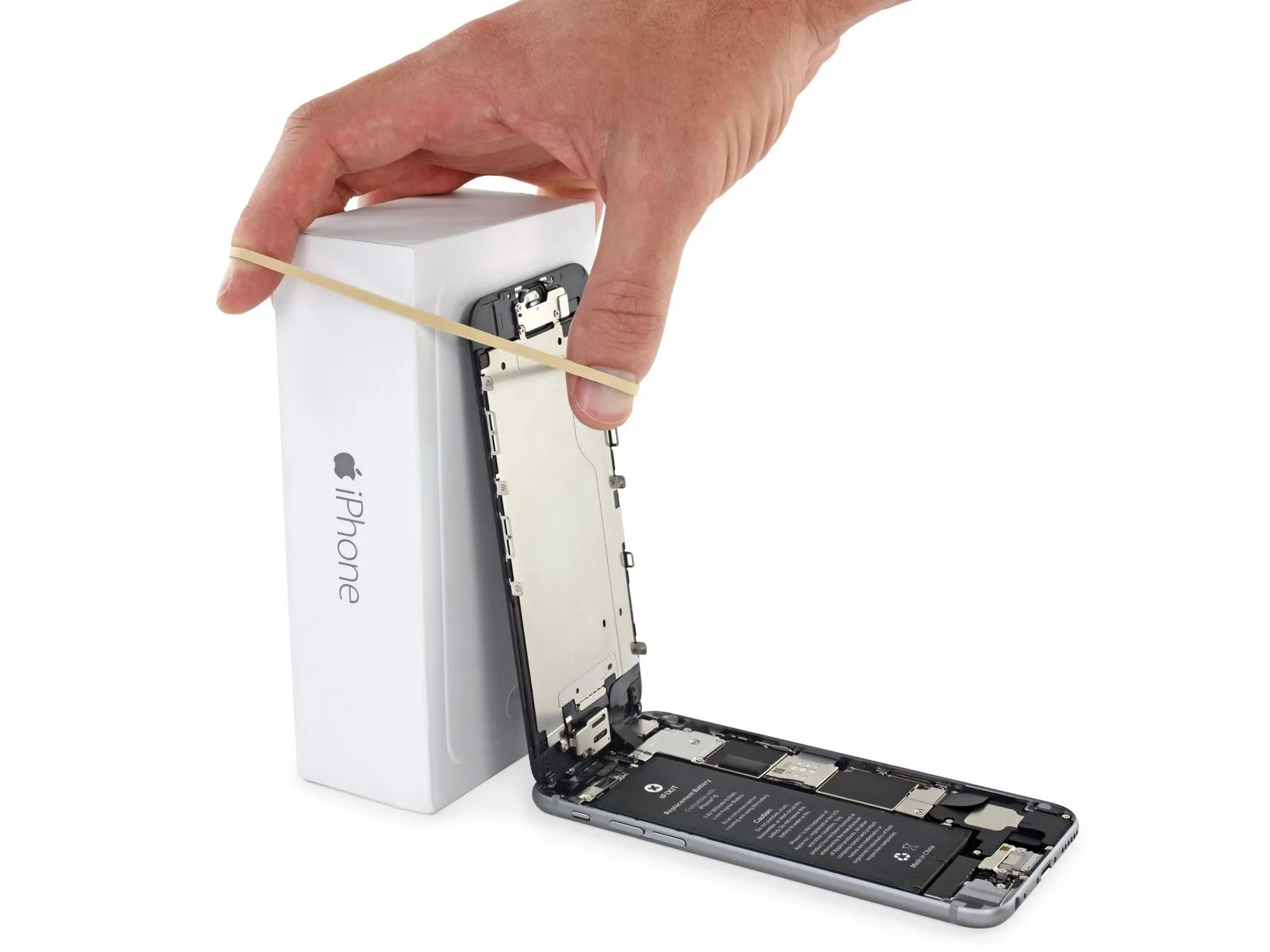
Carefully position the display at a roughly 90-degree angle, then secure it in an upright position using a support to prevent movement during the repair process.
If a dedicated calibration tool is unavailable, a factory-sealed, unopened can of soda can be substituted, provided it is the correct volume.
To avoid stressing the display's wiring during the repair process, secure it with a rubber band.
If a dedicated calibration tool is unavailable, a factory-sealed, unopened can of soda can be substituted, provided it is the correct volume.
To avoid stressing the display's wiring during the repair process, secure it with a rubber band.
Step 9 | Removing the battery connector bracket screws
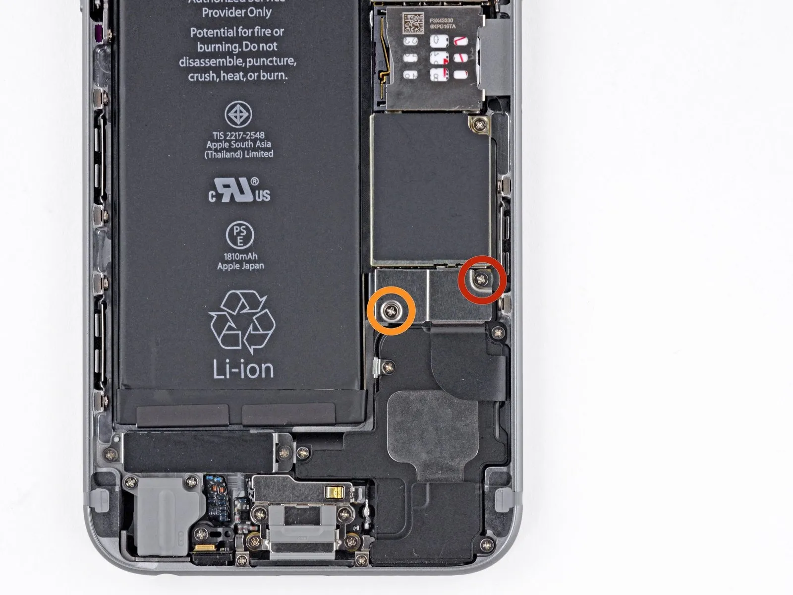
Using a Phillips screwdriver, detach the battery connector bracket by unscrewing the included fasteners.
A 2.2-millimeter screw is required.
A single screw, measuring 3.2 millimeters, is required.
Carefully note the location of every screw during disassembly, as reassembly requires placing each one in its original position to prevent potential damage to the device.
A 2.2-millimeter screw is required.
A single screw, measuring 3.2 millimeters, is required.
Carefully note the location of every screw during disassembly, as reassembly requires placing each one in its original position to prevent potential damage to the device.
Step 10
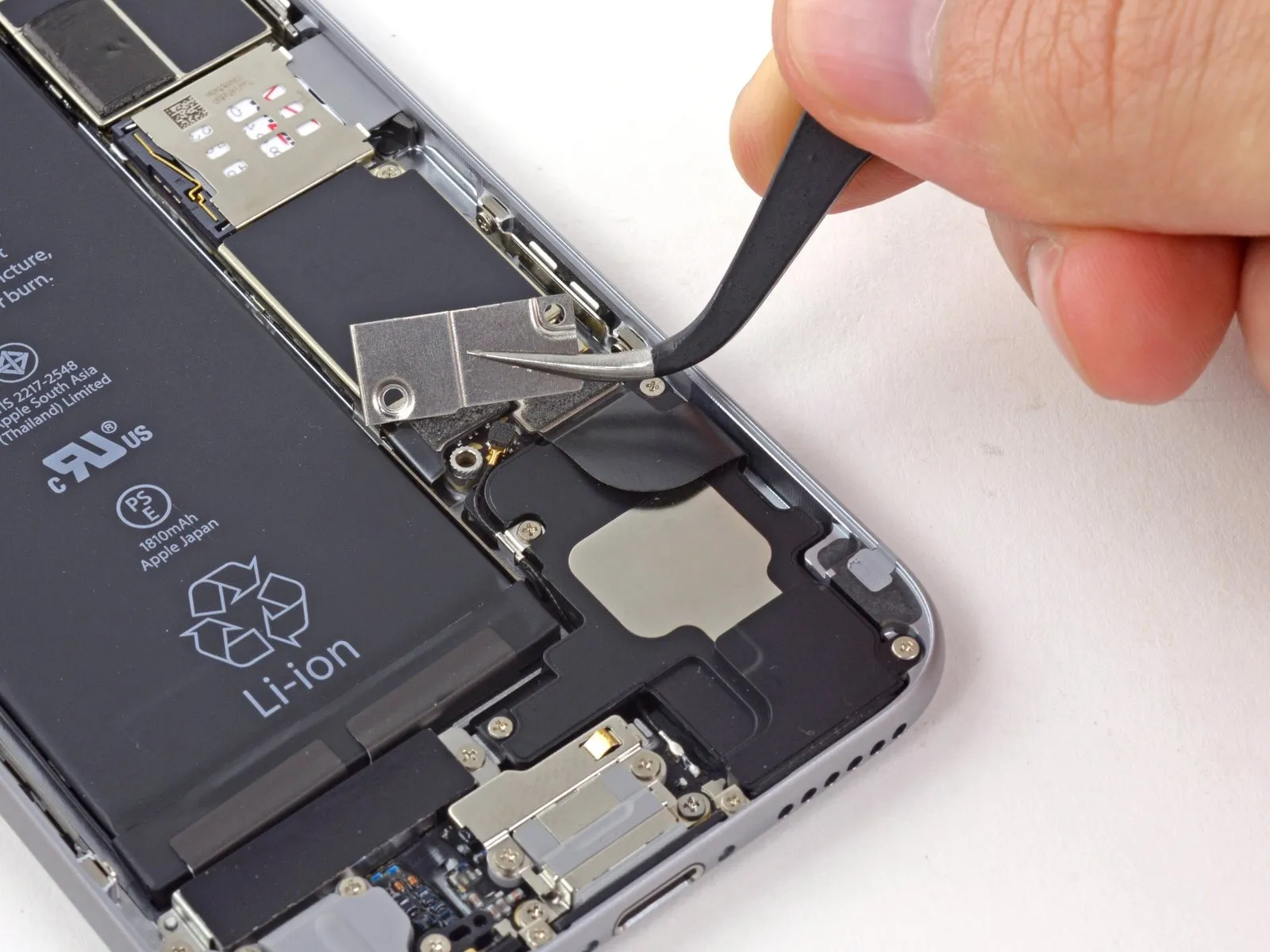
Detach the bracket securing the battery connector using a tri-point screwdriver.
Step 11 | Disconnecting the battery connector
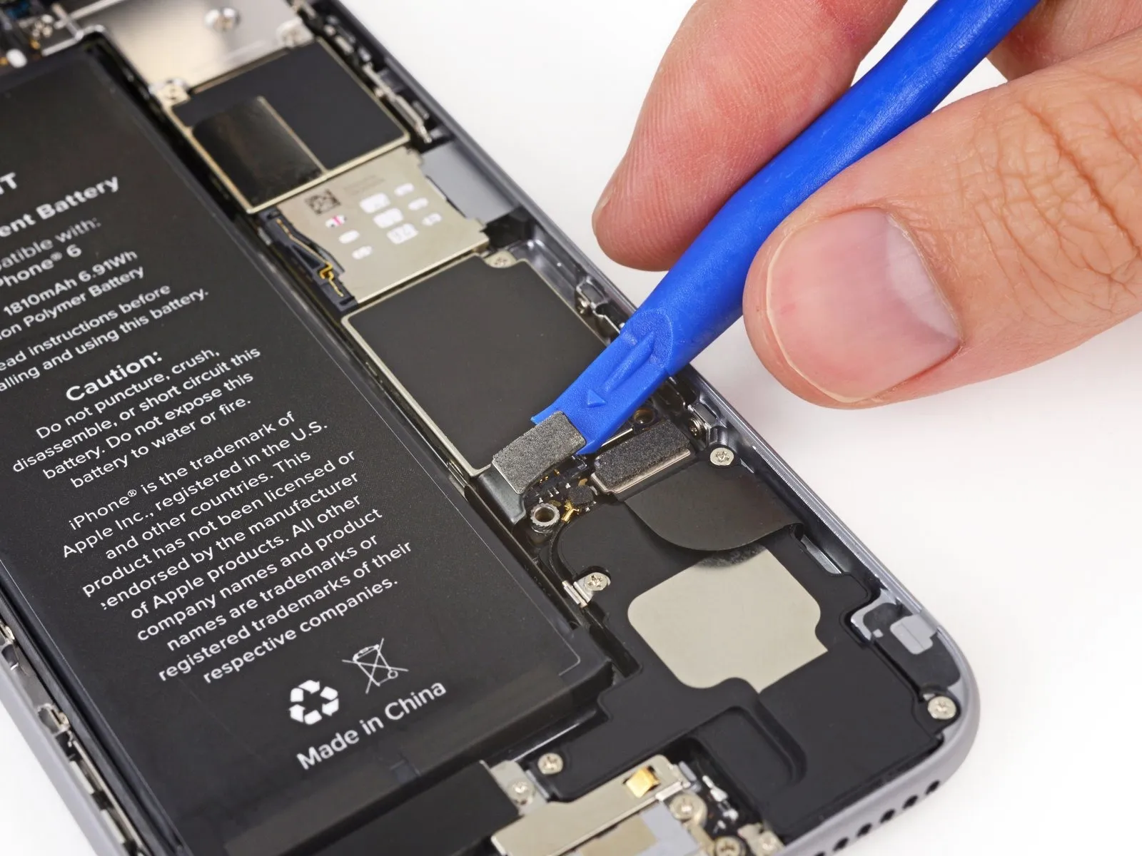
Carefully lift the battery connector away from its connection on the logic board using a plastic opening tool.
To avoid damaging the logic board, apply lifting force solely to the battery connector; applying pressure to the socket itself risks irreversible connector breakage.
To avoid damaging the logic board, apply lifting force solely to the battery connector; applying pressure to the socket itself risks irreversible connector breakage.
Step 12 | Removing the front panel assembly cable bracket screws
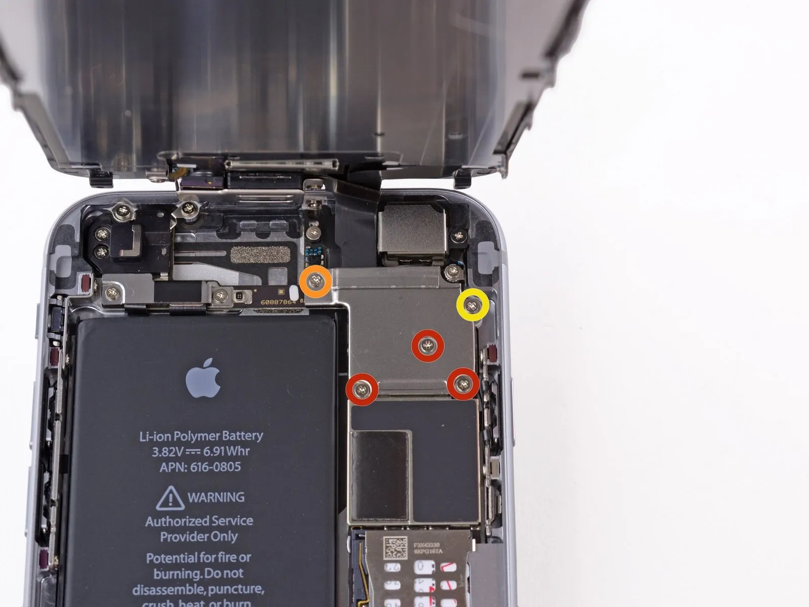
Using a Phillips screwdriver, detach the cable bracket from the front panel assembly by unscrewing the five screws holding it in place.
Use three screws, each measuring 1.2 millimeters.
A screw with a 1.7 mm head diameter is required.
A single screw, measuring 3.1 millimeters, is required.
Improper screw installation during reassembly can result in irreversible harm to the iPhone's logic board.
Use three screws, each measuring 1.2 millimeters.
A screw with a 1.7 mm head diameter is required.
A single screw, measuring 3.1 millimeters, is required.
Improper screw installation during reassembly can result in irreversible harm to the iPhone's logic board.
Step 13
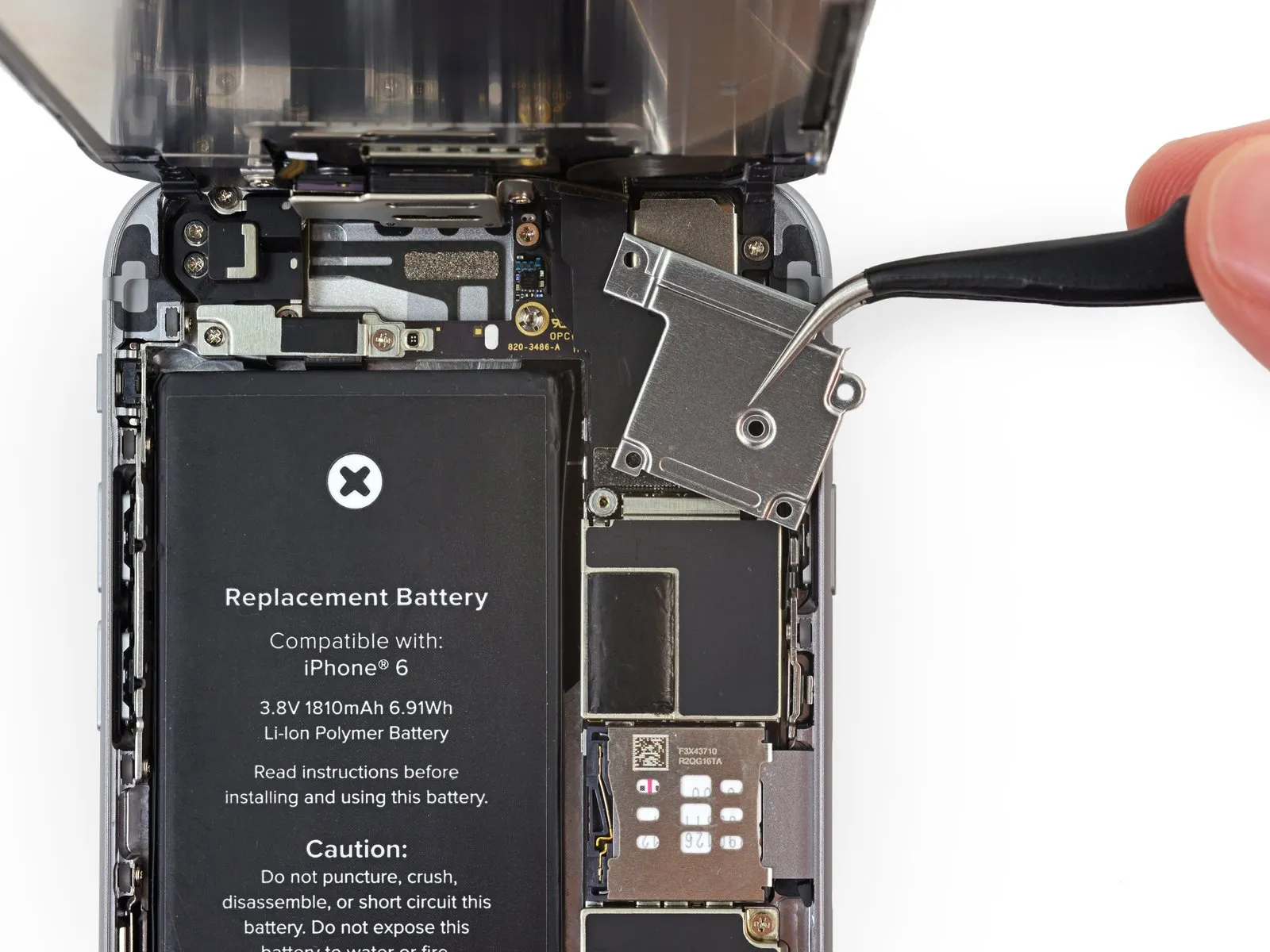
Detach the cable bracket securing the front panel assembly cable to the logic board.
Step 14
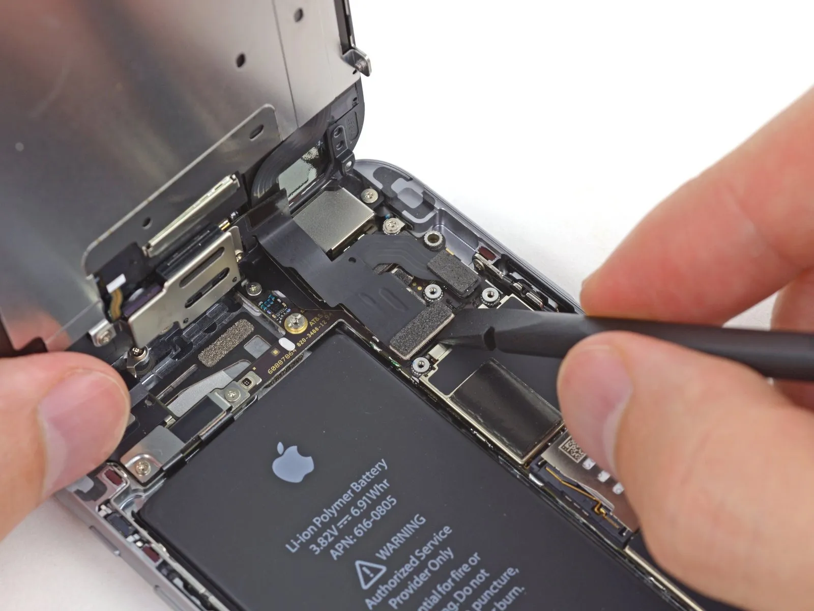

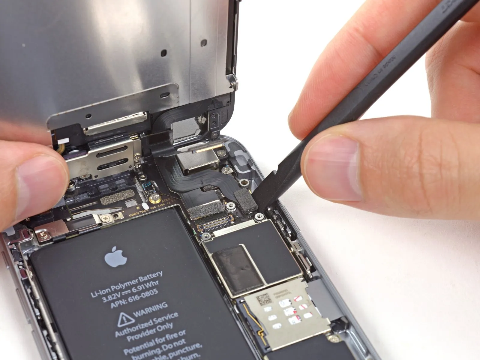
When proceeding with the following four steps, ensure that force is applied solely to the cable connectors themselves, avoiding any pressure on the corresponding sockets located on the logic board.
Carefully detach the front camera and sensor cable connector from its socket using a spudger or similar tool.
Carefully detach the front camera and sensor cable connector from its socket using a spudger or similar tool.
Step 15
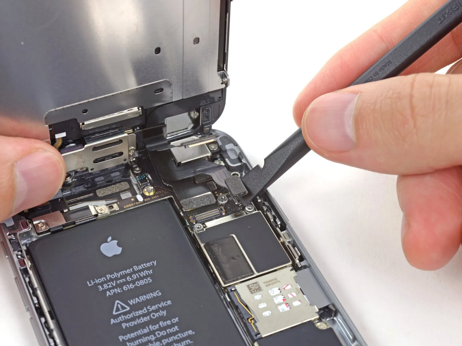
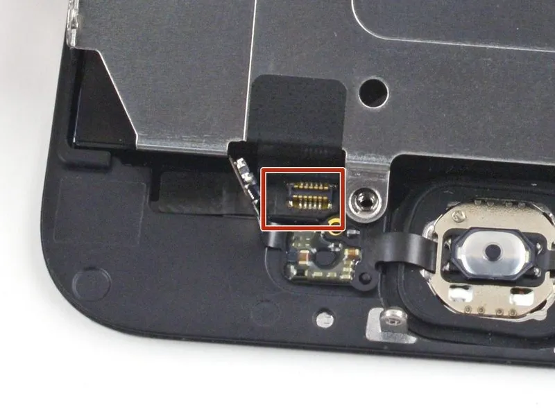
Carefully detach the home button cable connector using a spudger or similar tool, like a fingernail.
Step 16
Carefully align the 4mm hex key to the setscrew, ensuring it engages the threaded portion, then tighten the setscrew to a torque of 1.5 Nm using the hex key.
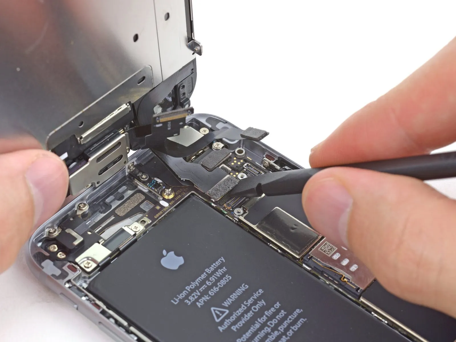
Prior to either detaching or reattaching the cable in this procedure, ensure the battery is disconnected.
Carefully separate the display data cable connector from its socket using a spudger or similar tool.
Should the display data cable become detached from its connector during reassembly, a blank screen or white lines might appear upon powering on the device. To resolve this, re-engage the cable with the connector and restart the phone; for a complete restart, disconnect and reconnect the battery connector.
Step 17

Using a 5/32-inch hex key, carefully tighten the four M4x8 pan head screws securing the fan assembly to the heatsink, ensuring a torque of 4.5 in-lbs to prevent damage.
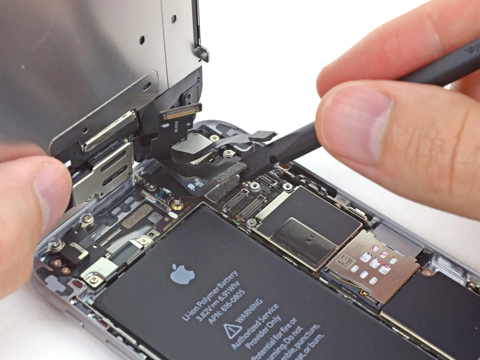
Carefully separate the digitizer cable connector from its socket using the flat spudger.
To avoid digitizer damage or component bending, when attaching the digitizer cable, apply pressure to opposing ends of the connector instead of the central area.
Carefully separate the digitizer cable connector from its socket using the flat spudger.
To avoid digitizer damage or component bending, when attaching the digitizer cable, apply pressure to opposing ends of the connector instead of the central area.
Step 18 | Separating front panel assembly and rear case

Using a 5/32-inch hex key, carefully tighten the four M4x8 screws securing the fan assembly to the heatsink, ensuring a torque of 4.5 in-lbs to prevent damage.
Detach the front panel assembly from the rear case.
Detach the front panel assembly from the rear case.
Step 19 | LCD Shield Plate
Carefully align the retaining clip, ensuring the two locating pins are properly seated within their corresponding holes, then secure it using 0.7 Newton-meters of torque with a calibrated torque wrench.
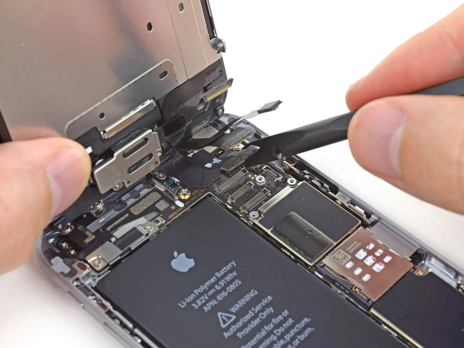
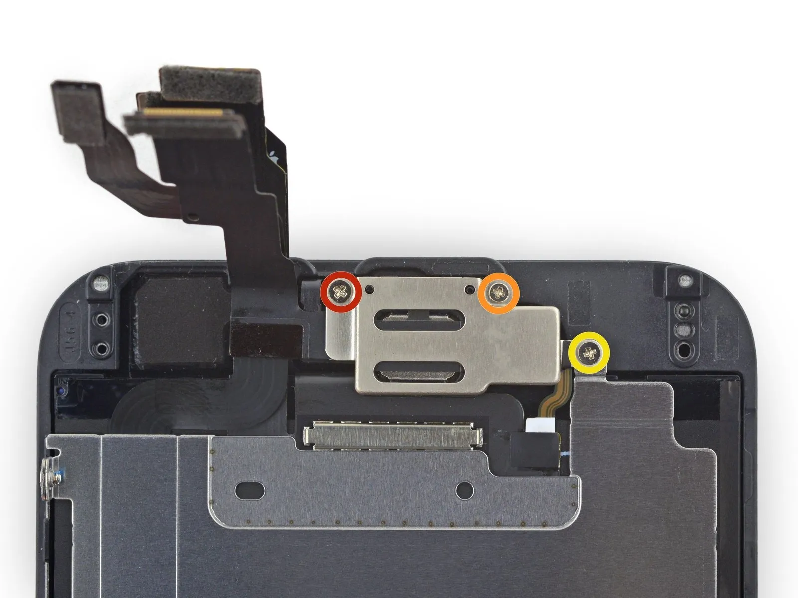
Using a Phillips screwdriver, detach the earpiece speaker/front-facing camera bracket by unscrewing the screws affixed to it.
A screw with a 2.3 mm head diameter is required.
A screw with a 3.0 mm diameter is required.
A screw with a 2.2 mm head diameter is required.
Using a Phillips screwdriver, detach the earpiece speaker/front-facing camera bracket by unscrewing the screws affixed to it.
A screw with a 2.3 mm head diameter is required.
A screw with a 3.0 mm diameter is required.
A screw with a 2.2 mm head diameter is required.
Step 20
Using a 5/32-inch hex key, carefully tighten the four M4 x 8mm screws securing the fan assembly to the heatsink, ensuring a torque of 4.5 in-lbs to prevent damage.
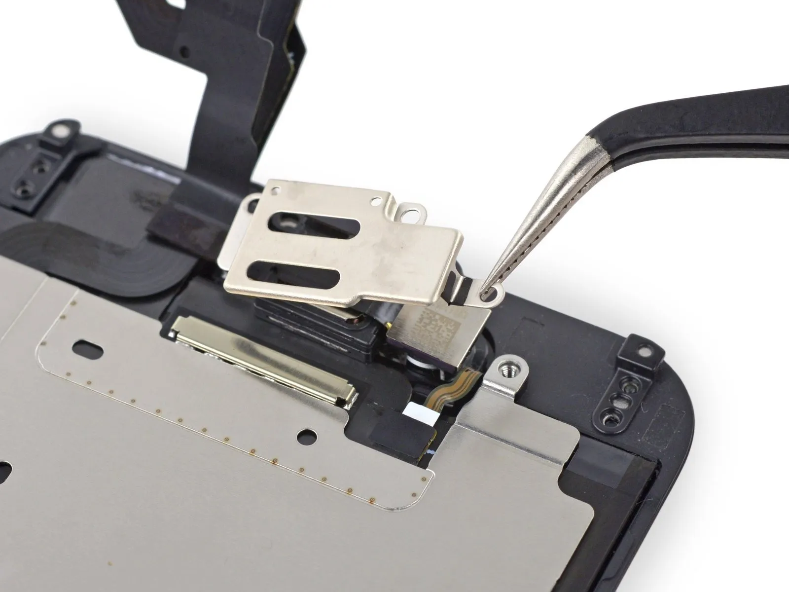
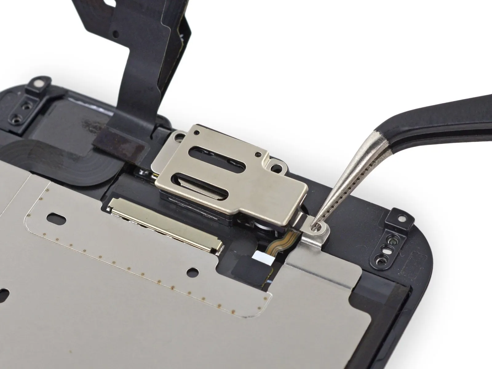
Detach the bracket securing the earpiece speaker and front-facing camera from the front panel.
Detach the bracket securing the earpiece speaker and front-facing camera from the front panel.
Step 21
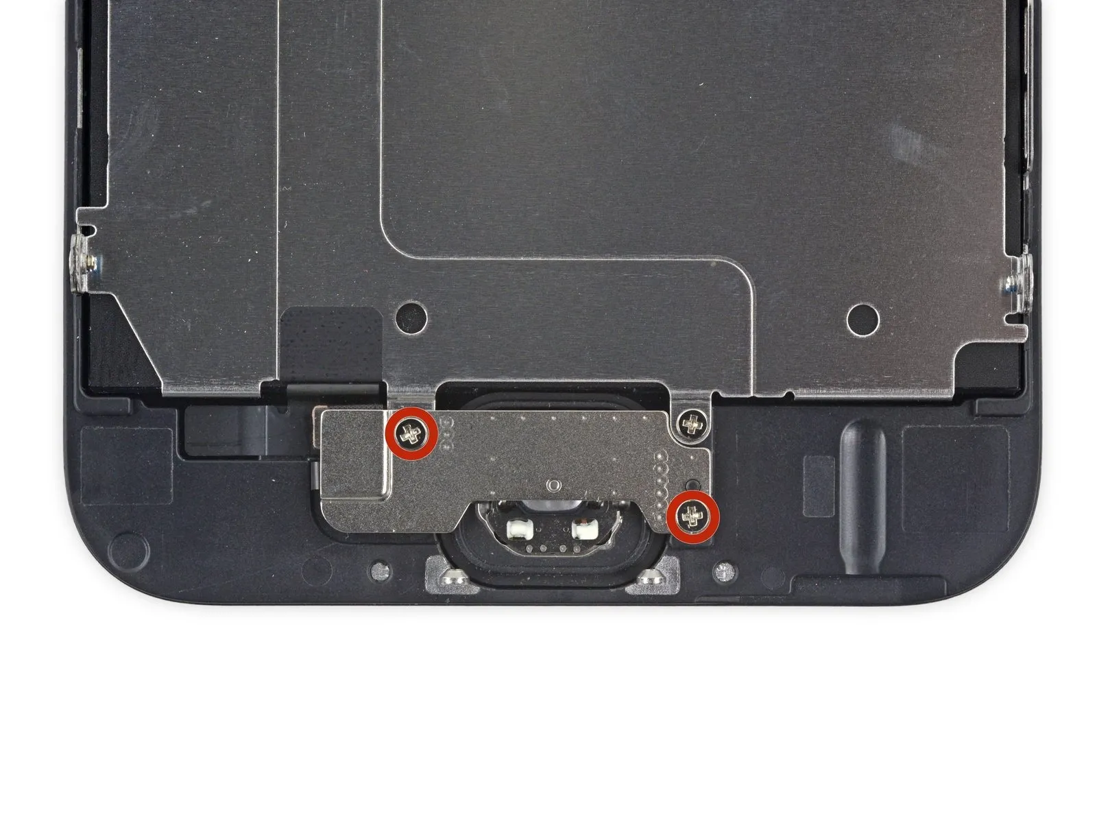
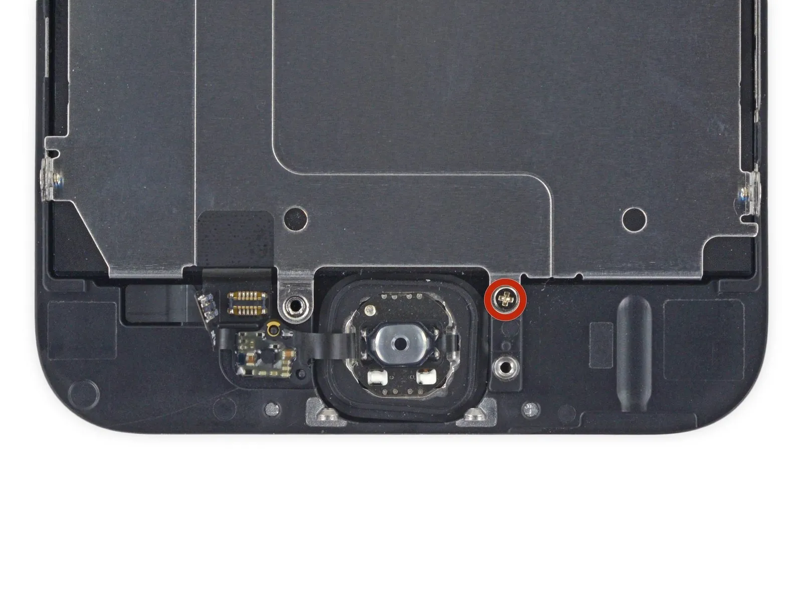
Using a Phillips #00 screwdriver, detach the home button bracket by unscrewing the two screws, each measuring 1.9 mm.
Step 22
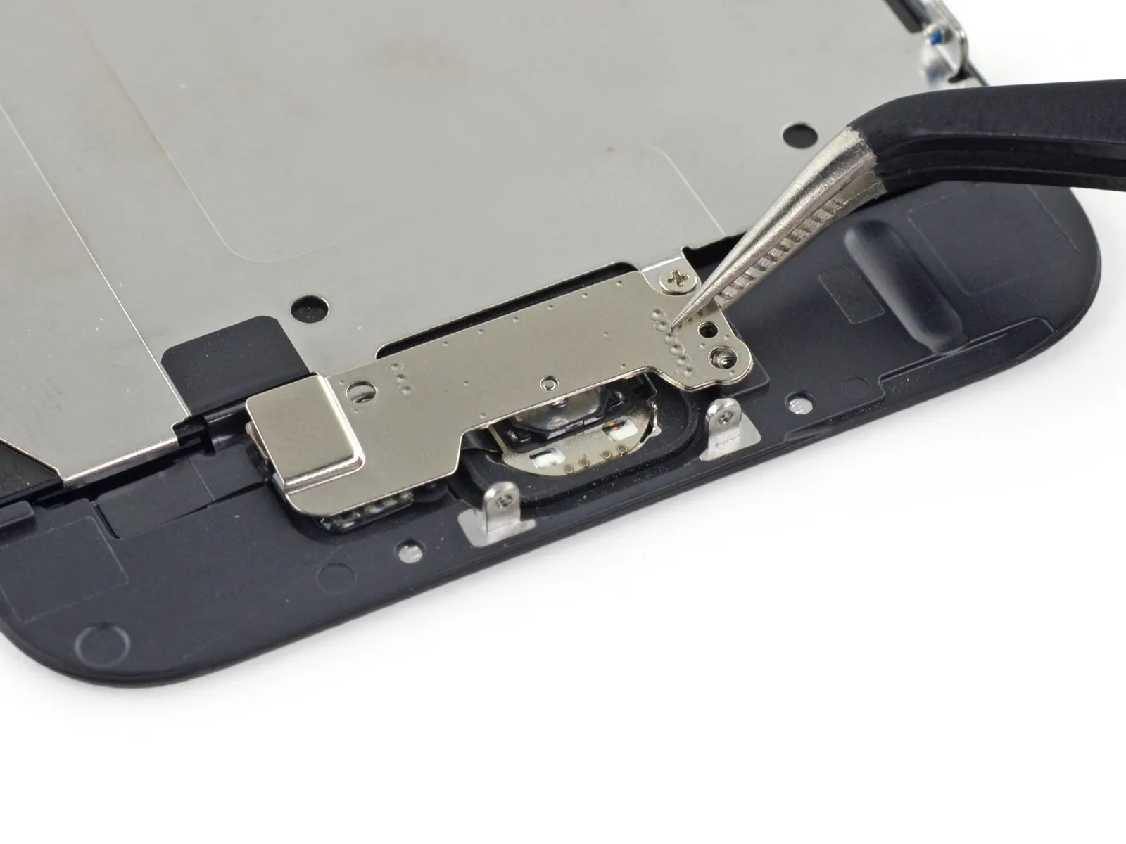
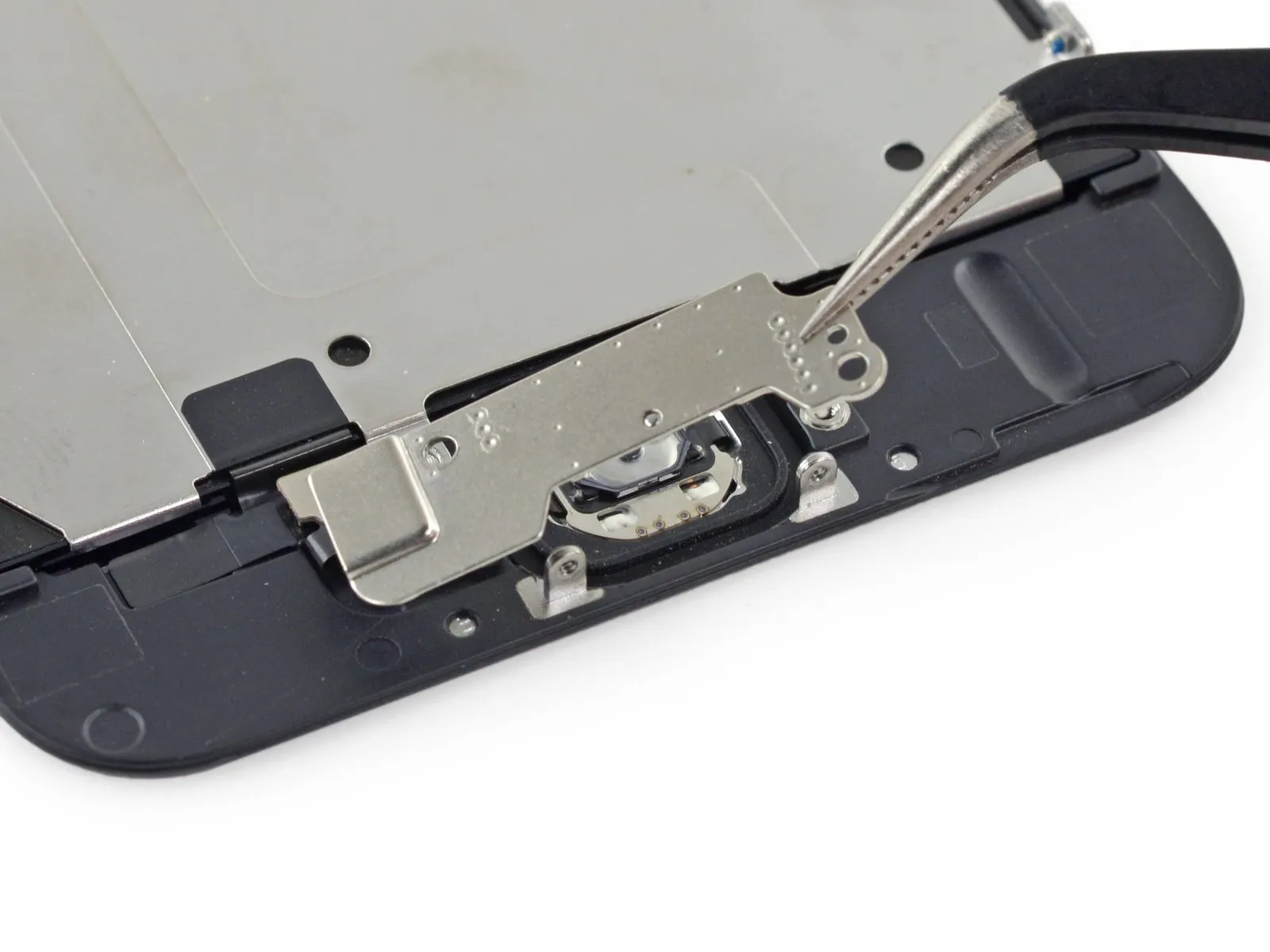
Detach the front panel's home button bracket.
Step 23


Carefully leverage a spudger to lift the home button cable connector upwards, releasing it from the home button assembly.
Step 24
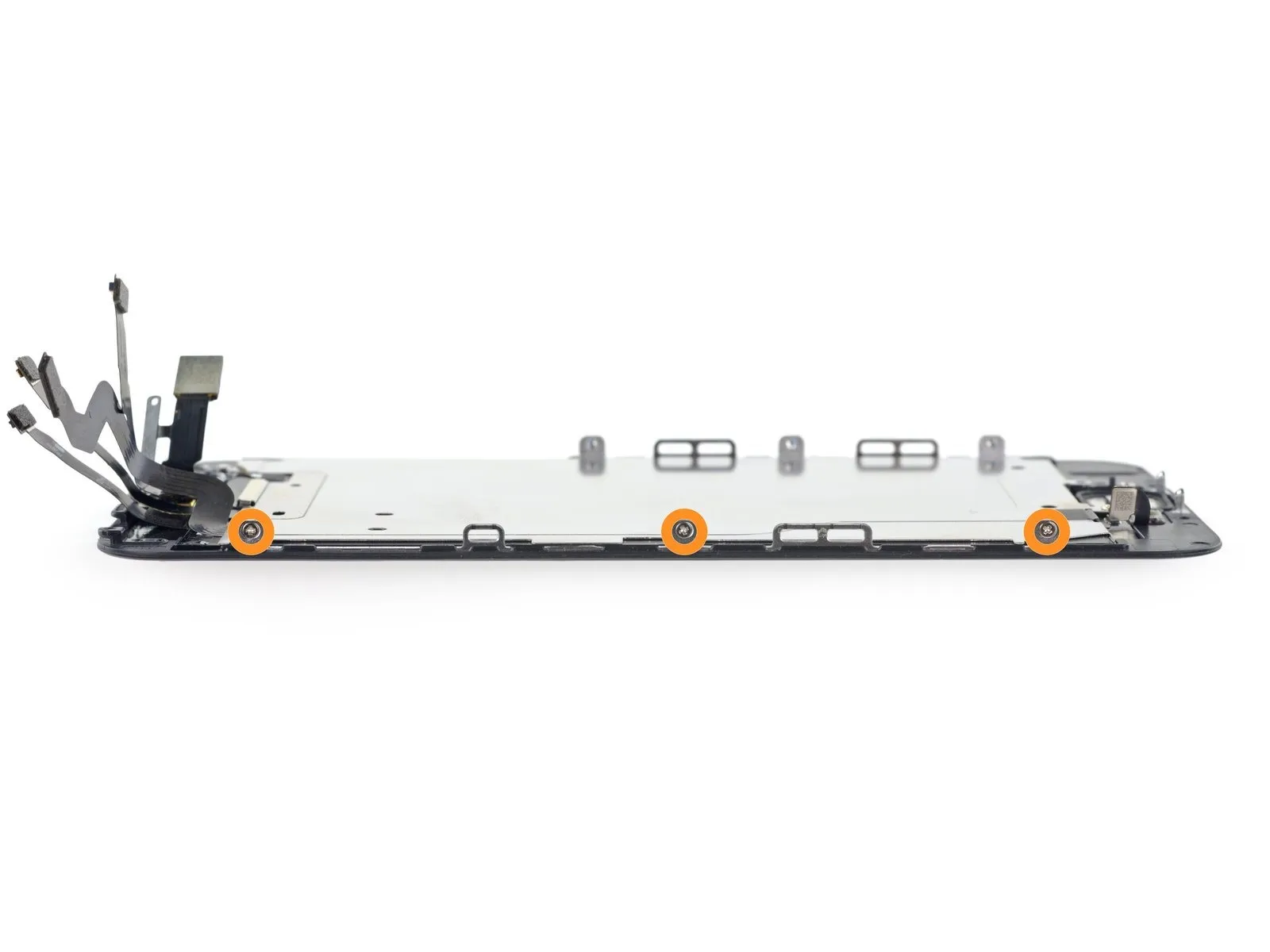
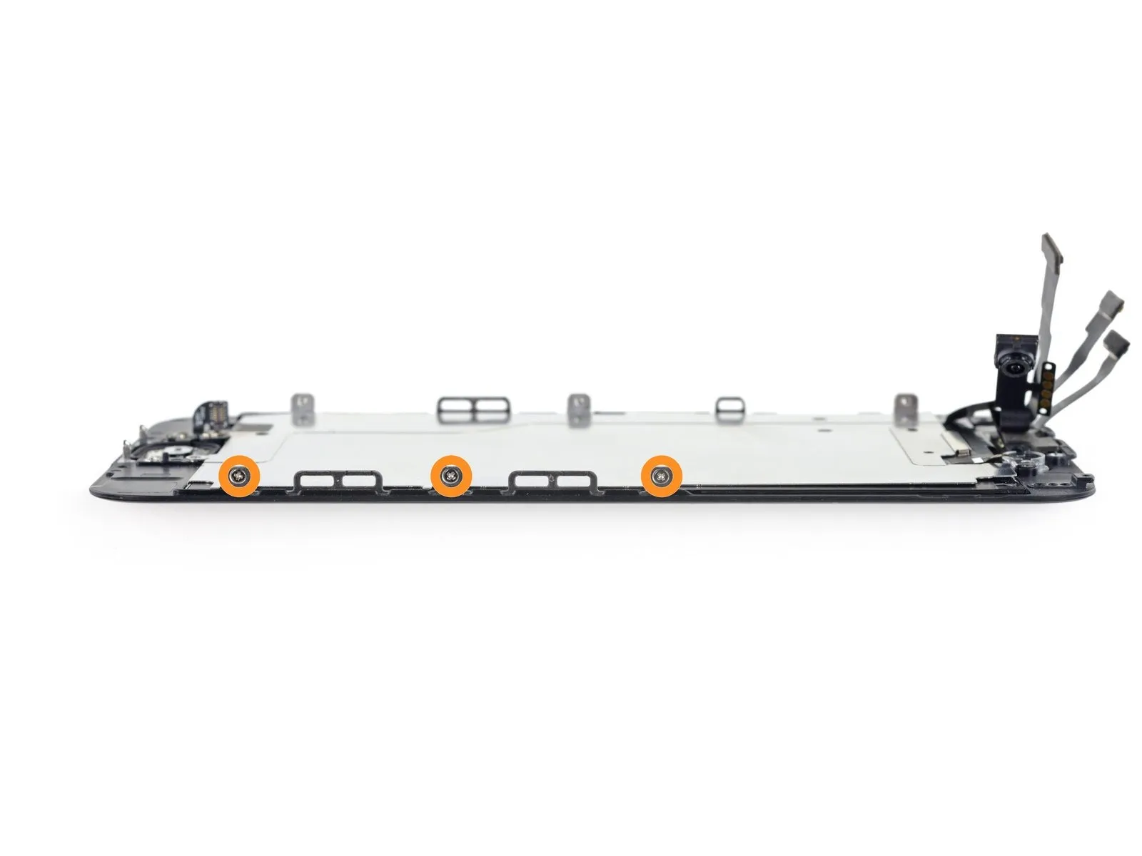
Using a Phillips #00 screwdriver, detach the LCD shield plate from the front panel by unscrewing the fasteners.
A screw with a 1.7-millimeter head diameter is required.
Secure the component with six screws, each measuring 1.6 mm, distributing them evenly with three fasteners per side.
A screw with a 1.7-millimeter head diameter is required.
Secure the component with six screws, each measuring 1.6 mm, distributing them evenly with three fasteners per side.
Step 25


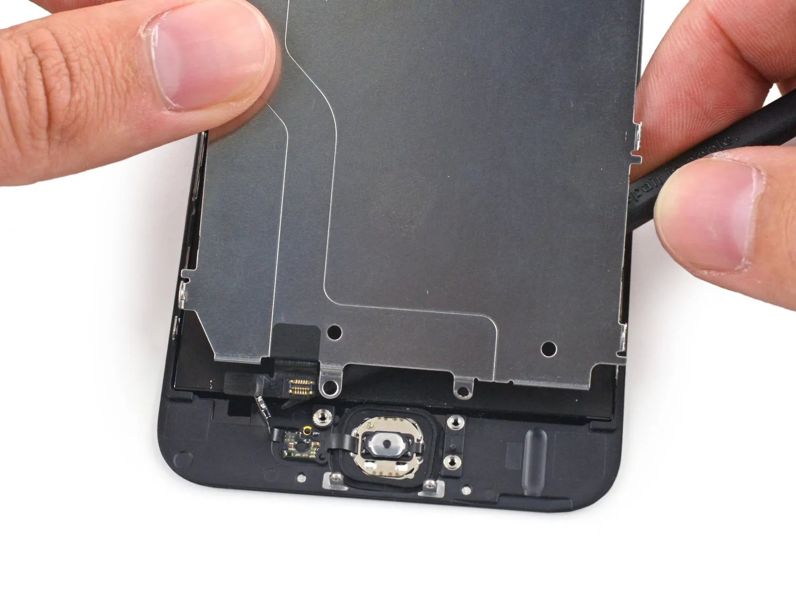
Carefully raise the LCD shield plate at its front-facing camera end a small amount.
The shield plate remains connected to the front panel through the home button cable; complete removal is not possible at this stage.
The shield plate remains connected to the front panel through the home button cable; complete removal is not possible at this stage.
Step 26
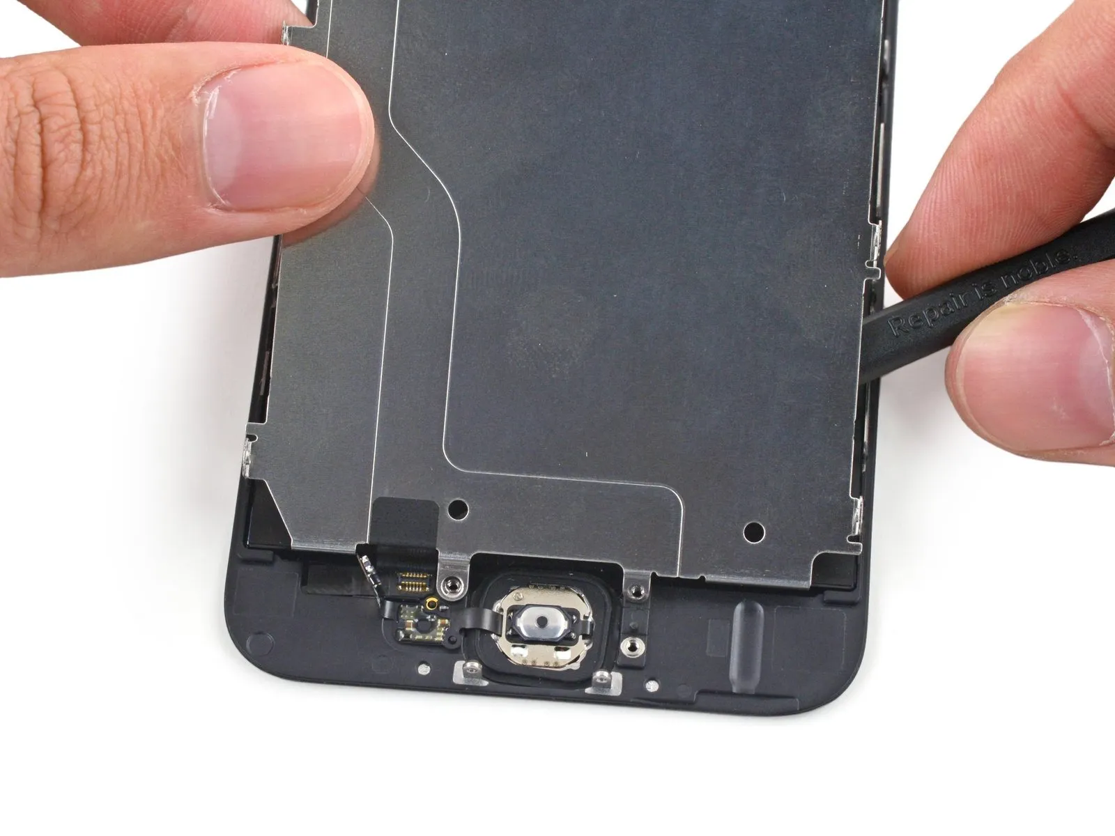
Using a 5/32-inch hex key, carefully tighten the four M4x8mm screws securing the motor assembly to the chassis, ensuring a torque of no more than 0.5 Nm to prevent damage.Using a spudger, carefully pry the shield plate away from the front panel, raising the home button cable connector.
Apply gentle warmth with an iOpener or hair dryer to loosen the adhesive securing the cable, allowing for easier separation if resistance is encountered.
Carefully detach the LCD shield plate.
Ensure the home button connector is properly positioned within the recess on the shield's plastic backing during reassembly.
Step 27


Using a 5/32-inch hex key, carefully tighten the four M4x8 pan head screws securing the fan assembly to the heatsink, ensuring a torque of 4.5 in-lbs to prevent damage.Carefully remove the black adhesive tape securing the home button cable.
Due to the tape's fragility, initiating the peeling process might require tweezers, but completing the task with just tweezers could prove difficult.
Due to the tape's fragility, initiating the peeling process might require tweezers, but completing the task with just tweezers could prove difficult.
Step 28
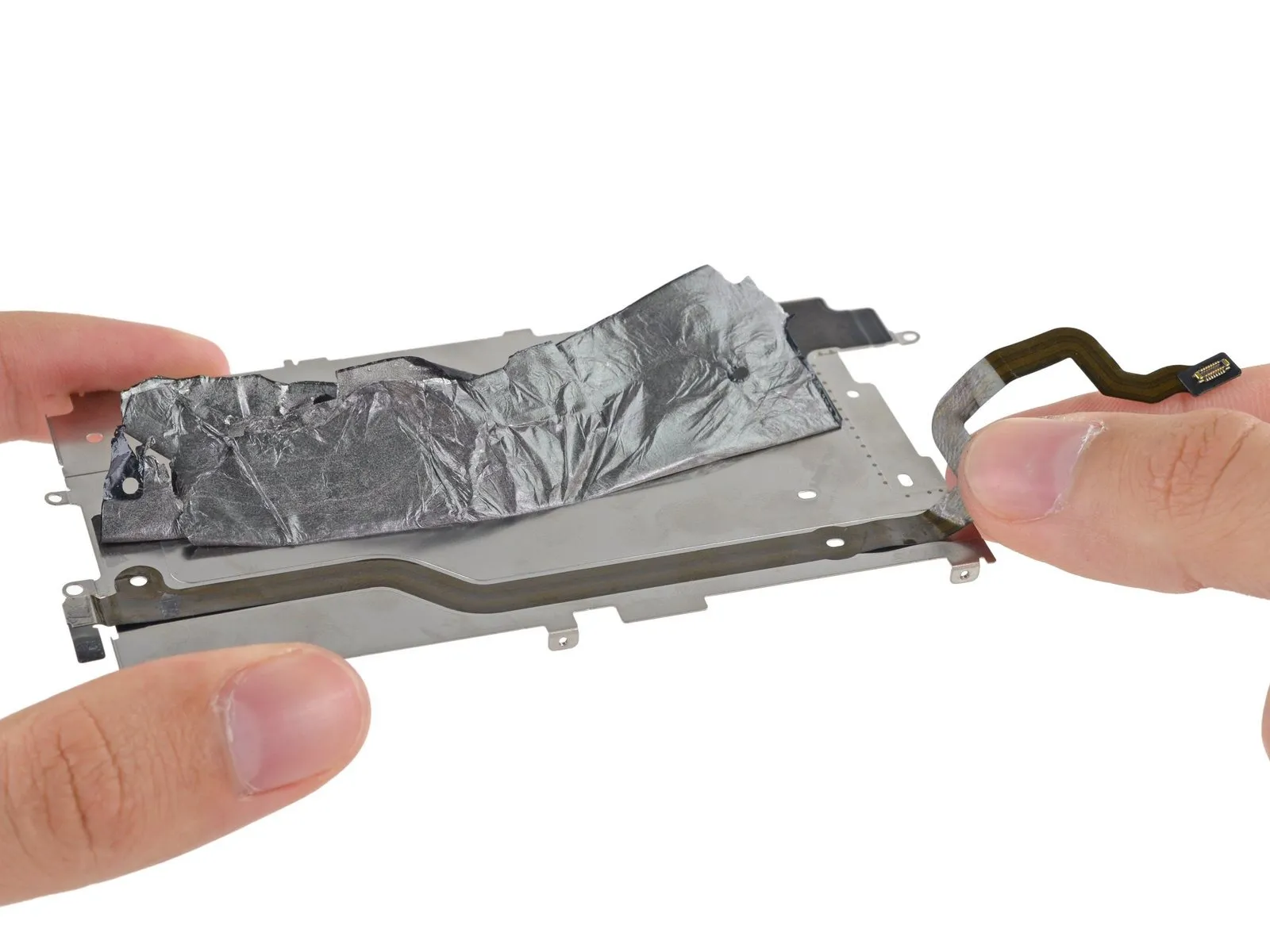

Using a 5/32-inch hex key, carefully tighten the four M4x8 pan head screws securing the fan assembly to the heatsink, ensuring a torque of 4 in-lbs to prevent damage.Using caution, detach the home button cable from the LCD shield plate by gently releasing the adhesive securing it.