iPhone 6 Antenna Flex Cable Replacement
To improve a weak Wi-Fi connection, consider substituting the interconnect cable or the Wi-Fi antenna attached to the logic board; this procedure details how to replace the interconnect cable and re-establish a strong Wi-Fi signal.
Step 1 | Pentalobe Screws

To prevent a fire or explosion hazard due to potential puncture, ensure the lithium-ion battery's charge level is less than 25% prior to beginning any disassembly procedures on your iPhone.
To prevent electrical shock or damage, ensure the iPhone is completely de-energized prior to starting the repair process.
Using a Pentalobe screwdriver, detach the two screws measuring 3.6 mm in length, which are positioned adjacent to the Lightning connector.
To prevent electrical shock or damage, ensure the iPhone is completely de-energized prior to starting the repair process.
Using a Pentalobe screwdriver, detach the two screws measuring 3.6 mm in length, which are positioned adjacent to the Lightning connector.
Step 2 | Anti-Clamp instructions


To simplify the opening process, the following two steps utilize the Anti-Clamp tool; if you do not have this tool, proceed to the instructions three steps further down.
Refer to the included guide for detailed procedures regarding Anti-Clamp operation.
To release the Anti-Clamp's arms, move the blue handle in a rearward direction.
Position the arms so they extend across the iPhone's left or right side.
Affix a suction cup to the front of the iPhone, close to the lower edge and directly over the home button, and another suction cup to the rear of the device in a similar location.
Apply vacuum by pressing the cups firmly against the surface you intend to work on.
To improve the Anti-Clamp's adherence if the iPhone's exterior feels excessively slick, apply tape to the device's surface to increase friction.
Step 3


Moving the blue handle in a forward direction will engage the locking mechanism for the arms.
Rotate the handle fully, completing a 360-degree turn, observing for the point when the cups begin to expand.
Maintain parallel positioning of the suction cups; should misalignment occur, gently release the suction cups’ hold and reposition the arms.
Once sufficient space is created by the Anti-Clamp, slide a separation tool beneath the display.
To ensure adequate separation, reposition the handle by 90 degrees.
Allow the Anti-Clamp device to function; apply no more than a 90-degree rotation per adjustment, pausing several seconds between each incremental tightening.
Step 4 | Manual Opening Procedure

Lacking an Anti-Clamp tool, secure the front panel with a single suction cup for lifting.
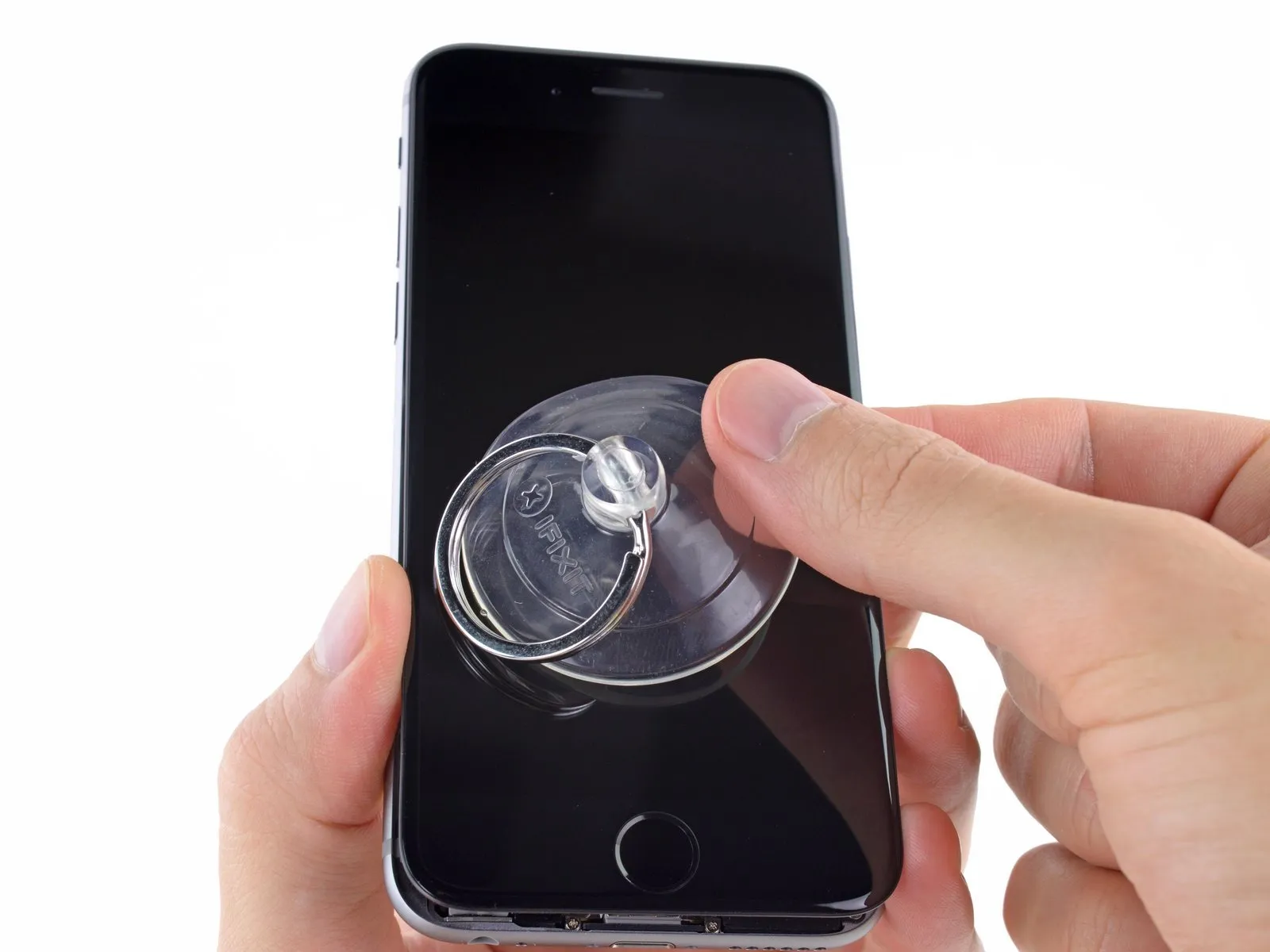
Position a suction cup directly on the display surface, situated slightly higher than the home button's location.
Ensure the screen is firmly seated against the cup to create a complete seal.
To facilitate suction cup attachment when the display has severe cracking, apply a sheet of clear packing tape across the damaged area; as an alternative, a robust adhesive tape can be used directly in place of the suction cup. Should neither of these methods prove effective, superglue can be employed to secure the suction cup to the fractured screen.
Step 5
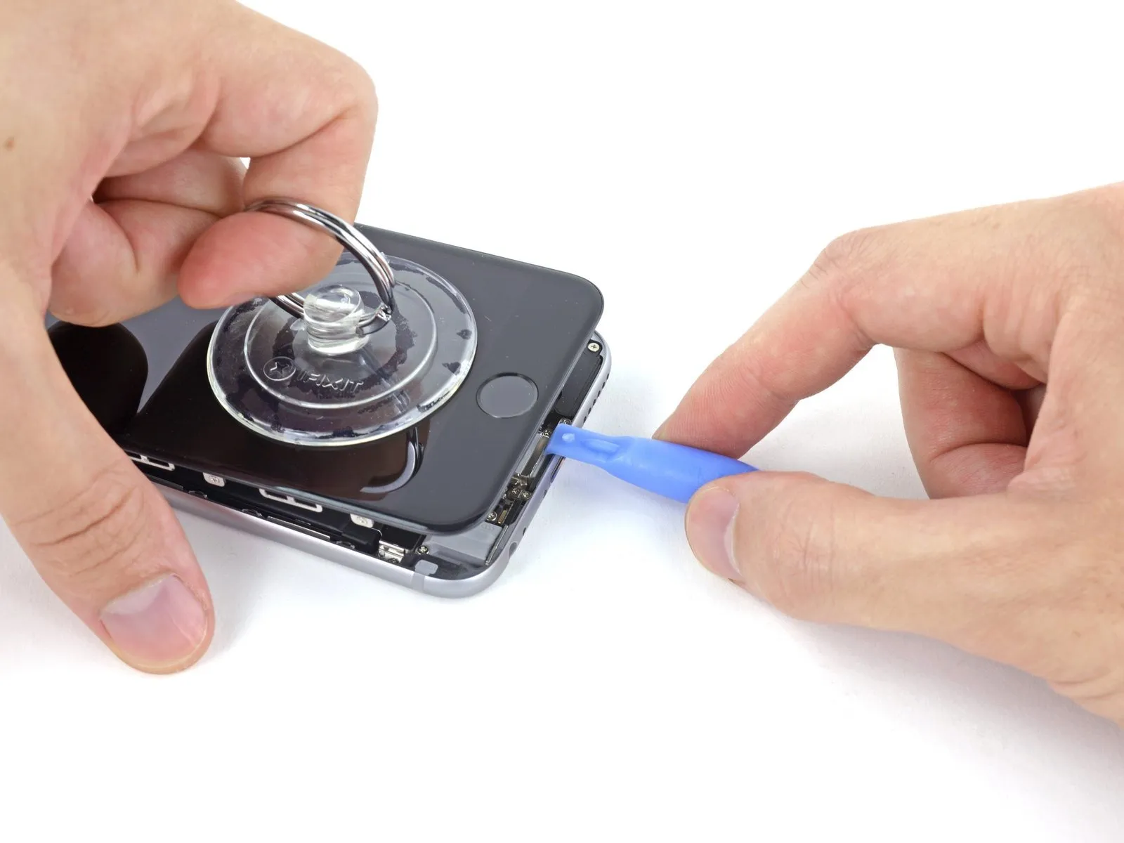
Using one hand to secure the iPhone, lift the suction cup upwards to gently create a small gap between the front panel and the rear enclosure.
Exercise caution and use steady, even pressure when installing the display assembly, as its fit is significantly more snug than typical device components.
Carefully separate the rear case from the display assembly by gently levering it downwards with a plastic opening tool, maintaining upward traction on the display with the suction cup.
To release the front panel assembly from the rear case, carefully disengage the multiple retaining clips, potentially requiring the coordinated use of both the suction cup and plastic opening tool.
Step 6

To detach the suction cup, depress the plastic projection that maintains the airtight seal.
Detach the display assembly's suction cup.
Detach the display assembly's suction cup.
Step 7 | Opening up the phone

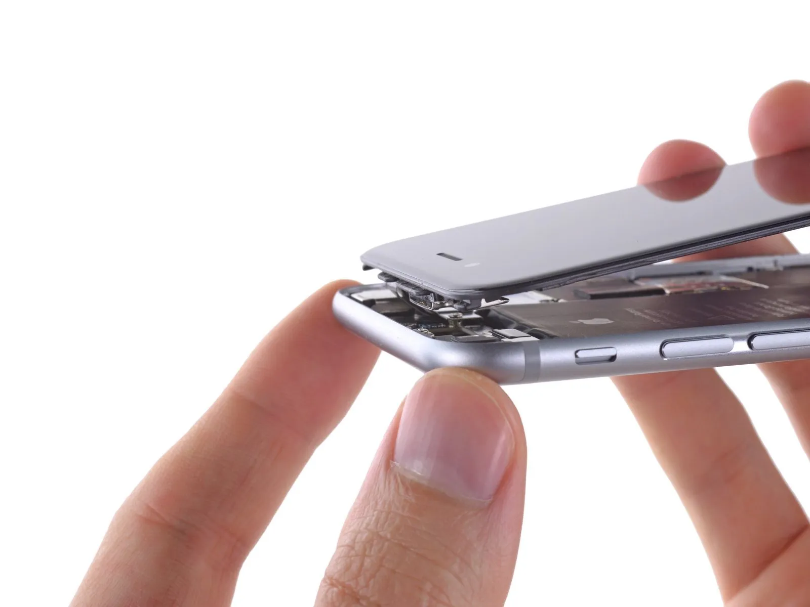
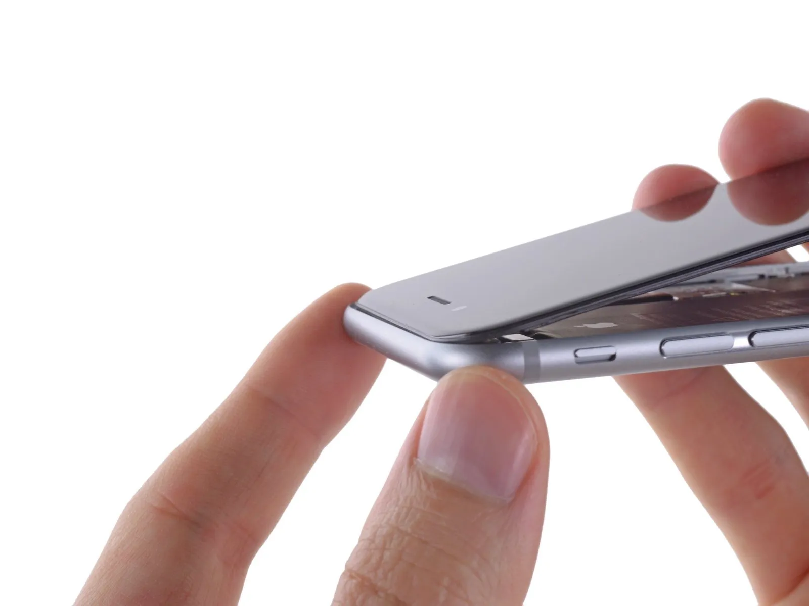
Using the phone's upper edge as a pivot point, carefully separate the front panel assembly from the rear case by gently moving the home button end outward.
The front panel's upper edge incorporates multiple clips that function as a partial hinge.
Ensure the clips, positioned directly beneath the rear case's upper border, are properly aligned before sliding the front panel upwards. The front panel's top edge should be perfectly level with the rear case's top edge during this movement.
Step 8

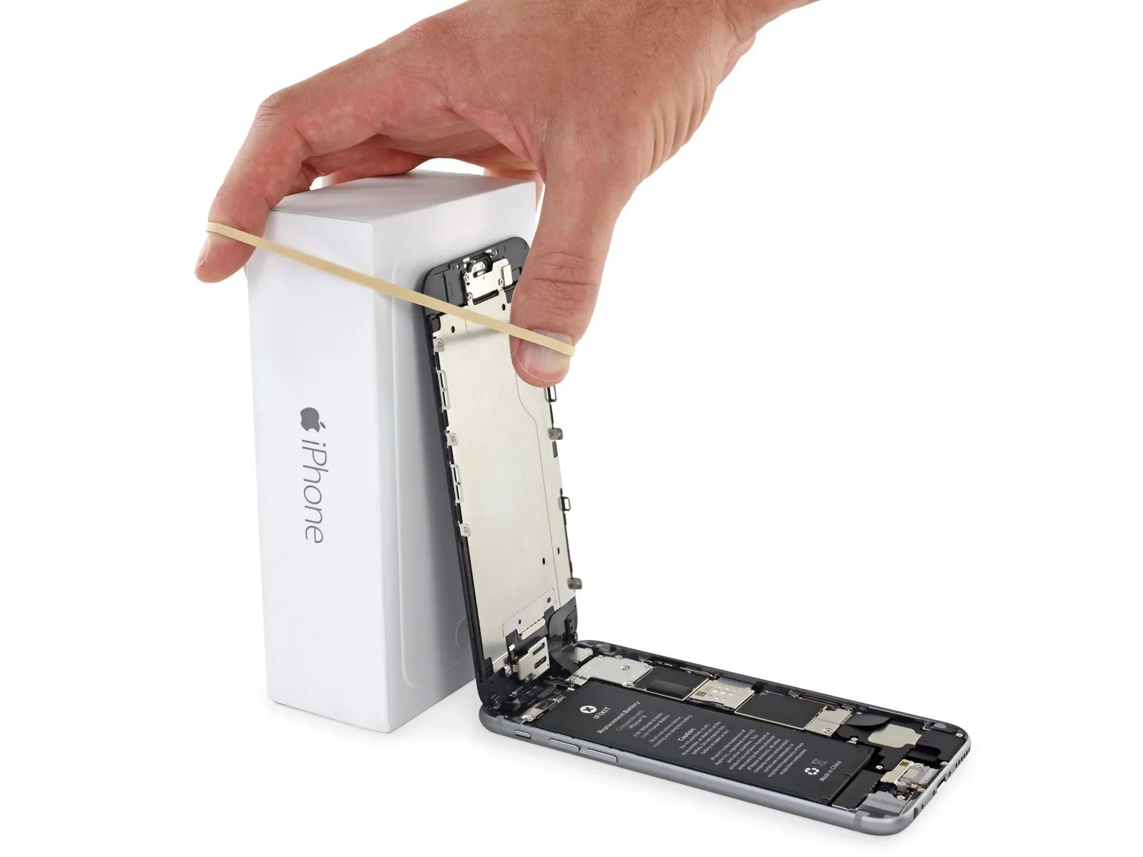
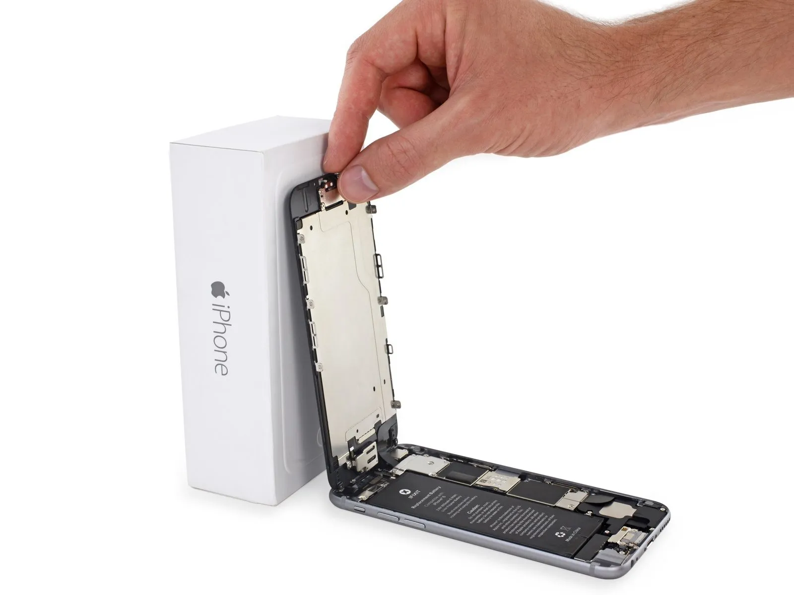
Carefully position the display at a roughly 90-degree angle, then secure it in a supported position using a prop to prevent it from moving during the repair process.
If a suitable container is unavailable, a factory-sealed can of soda can be substituted.
To avoid stressing the display's wiring during the repair process, secure the display with a rubber band.
If a suitable container is unavailable, a factory-sealed can of soda can be substituted.
To avoid stressing the display's wiring during the repair process, secure the display with a rubber band.
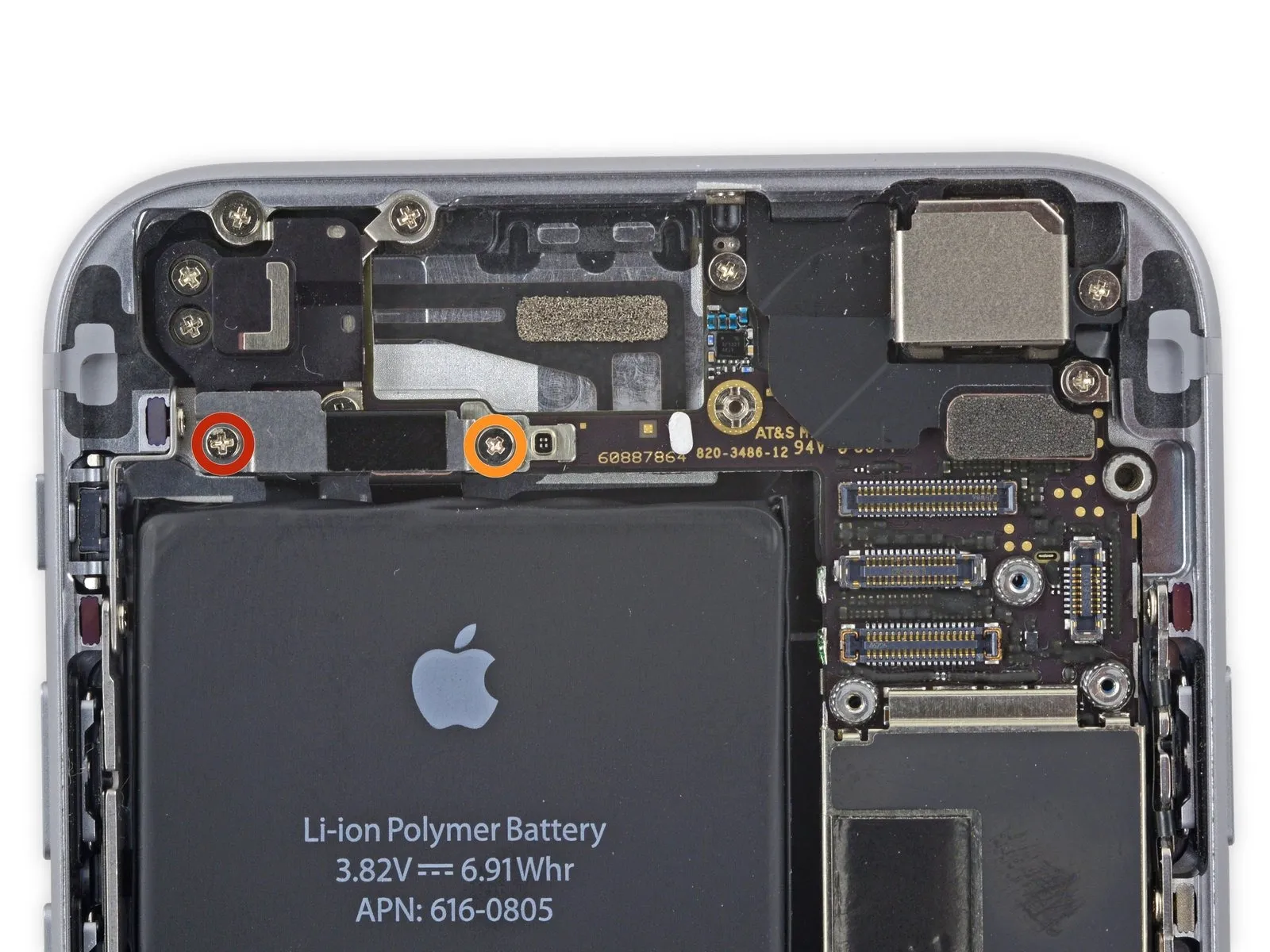
Step 9 | Removing the battery connector bracket screws
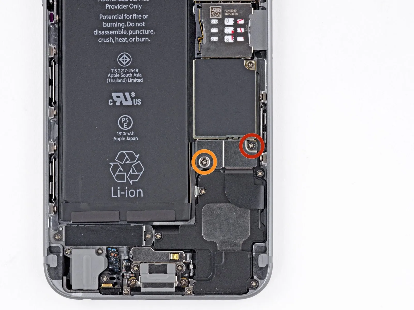
Using a Phillips screwdriver, detach the battery connector bracket by unscrewing the included fasteners.
A single screw, measuring 2.2 millimeters, is required.
A single screw, measuring 3.2 millimeters, is required.
Carefully note the location of every screw during disassembly, as reassembly requires placing each one in its original position to prevent potential damage to the device.
A single screw, measuring 2.2 millimeters, is required.
A single screw, measuring 3.2 millimeters, is required.
Carefully note the location of every screw during disassembly, as reassembly requires placing each one in its original position to prevent potential damage to the device.
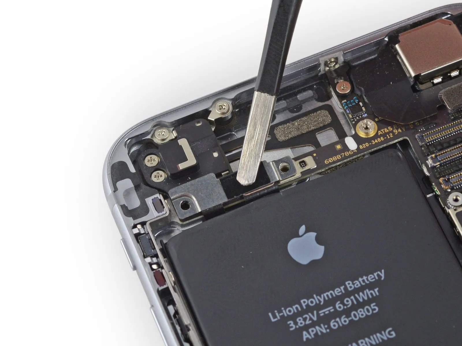
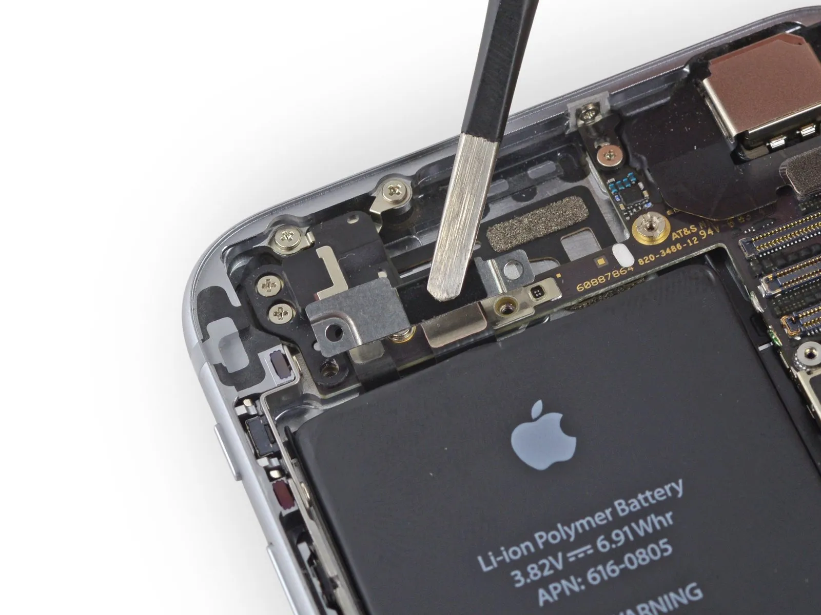
Step 10
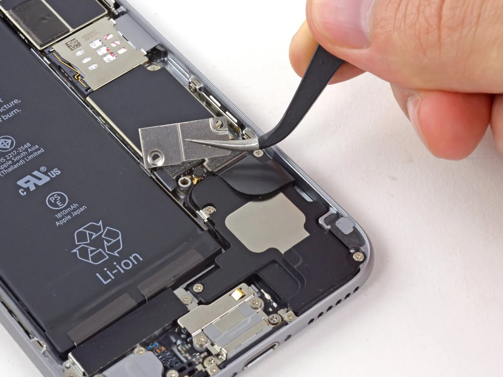
Detach the bracket securing the battery connector using a tri-point screwdriver, ensuring no damage occurs to surrounding components.
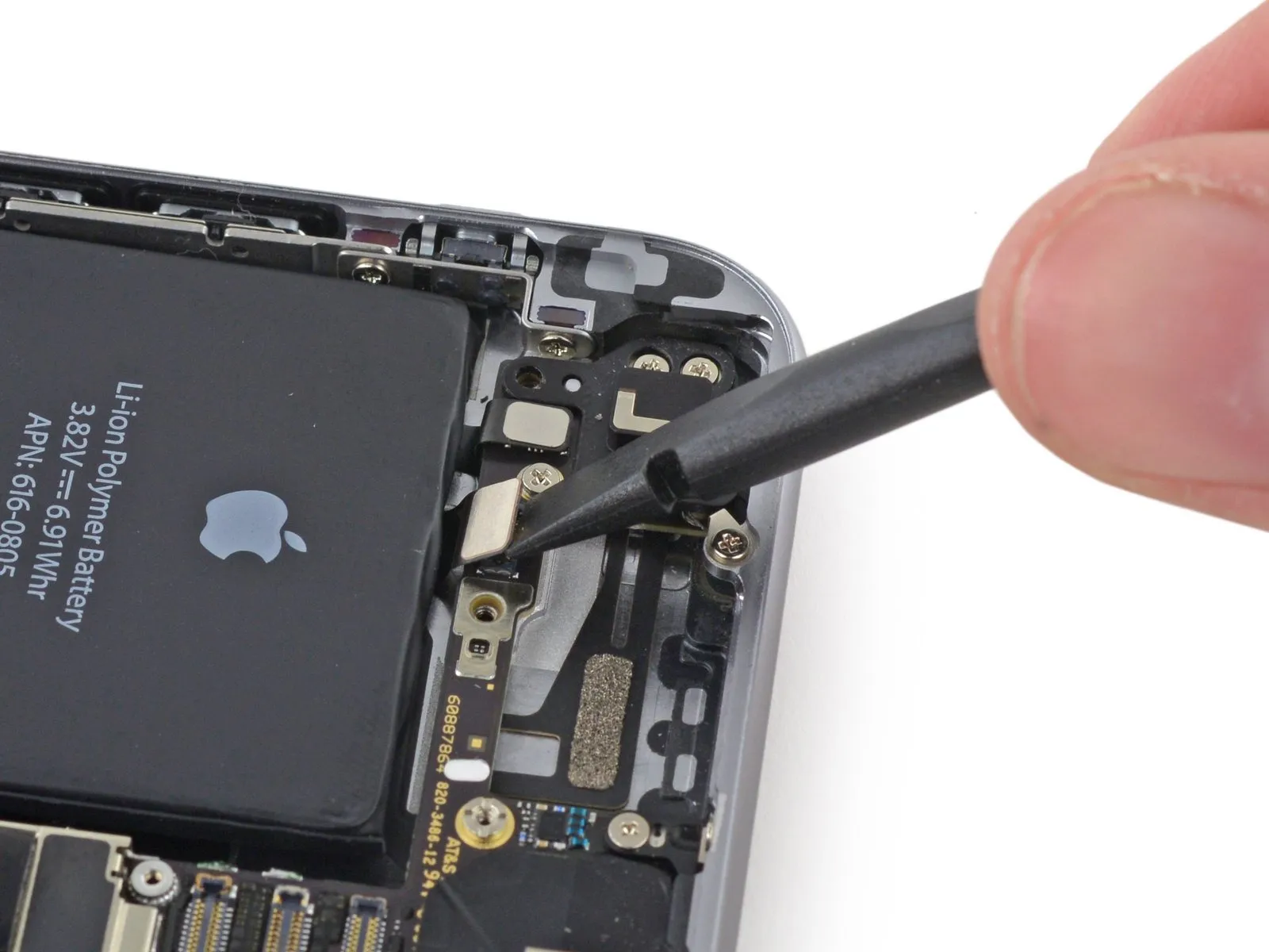
Step 11 | Disconnecting the battery connector
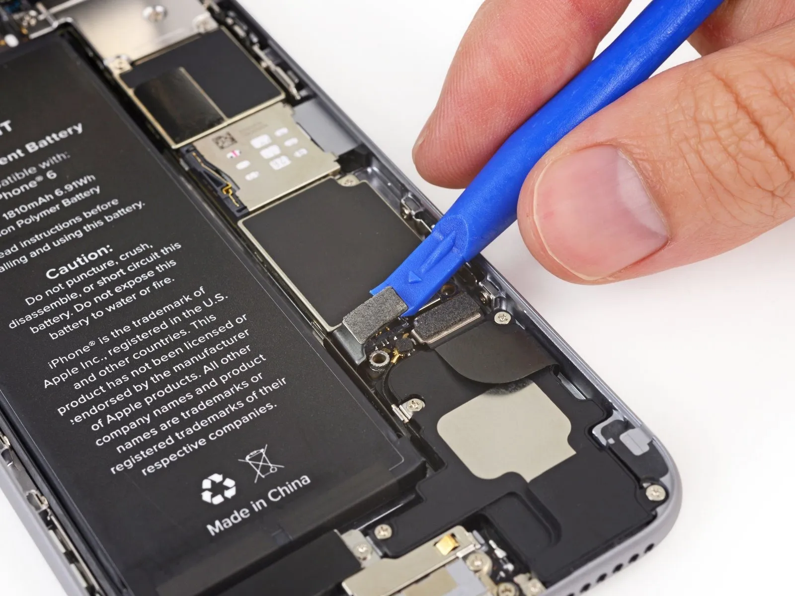
Carefully lift the battery connector away from its corresponding socket on the logic board, employing a plastic opening tool to avoid damage.
To prevent damage, lift solely on the battery connector itself; applying force to the logic board socket risks complete connector failure.
To prevent damage, lift solely on the battery connector itself; applying force to the logic board socket risks complete connector failure.
Step 12 | Removing the front panel assembly cable bracket screws
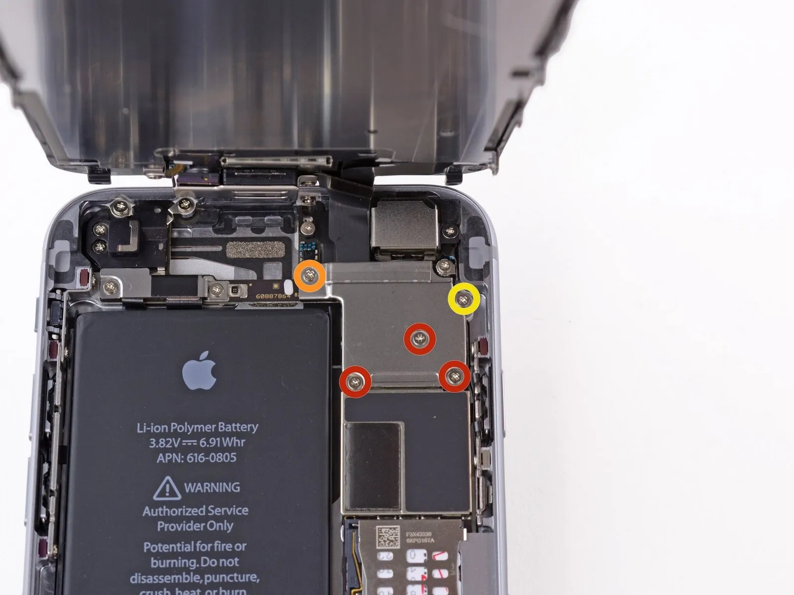
Using a Phillips screwdriver, detach the five screws that fasten the cable bracket to the front panel assembly.
Use three screws, each measuring 1.2 millimeters.
A screw with a 1.7-millimeter head diameter is required.
A single screw, measuring 3.1 millimeters, is required.
Improper screw installation during reassembly can result in irreversible harm to the iPhone's logic board.
Use three screws, each measuring 1.2 millimeters.
A screw with a 1.7-millimeter head diameter is required.
A single screw, measuring 3.1 millimeters, is required.
Improper screw installation during reassembly can result in irreversible harm to the iPhone's logic board.
Step 13
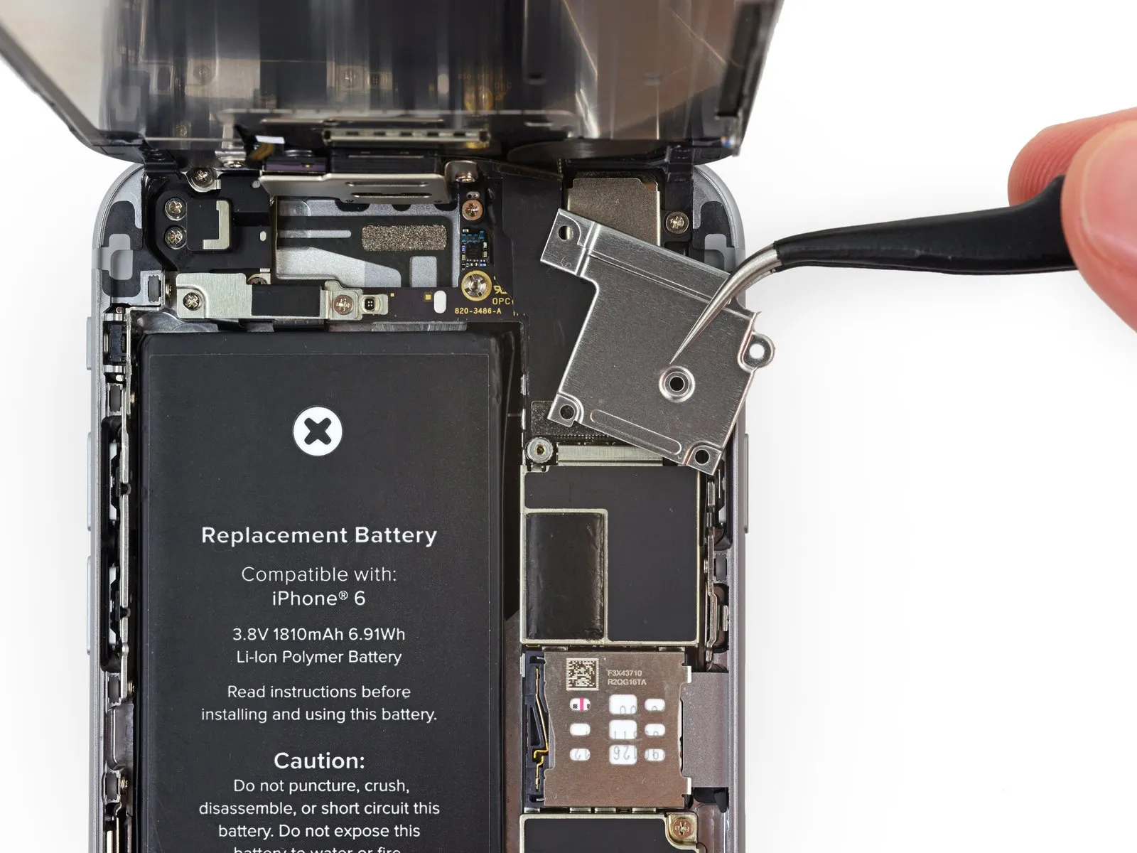
Detach the bracket securing the front panel assembly cable to the logic board.
Step 14

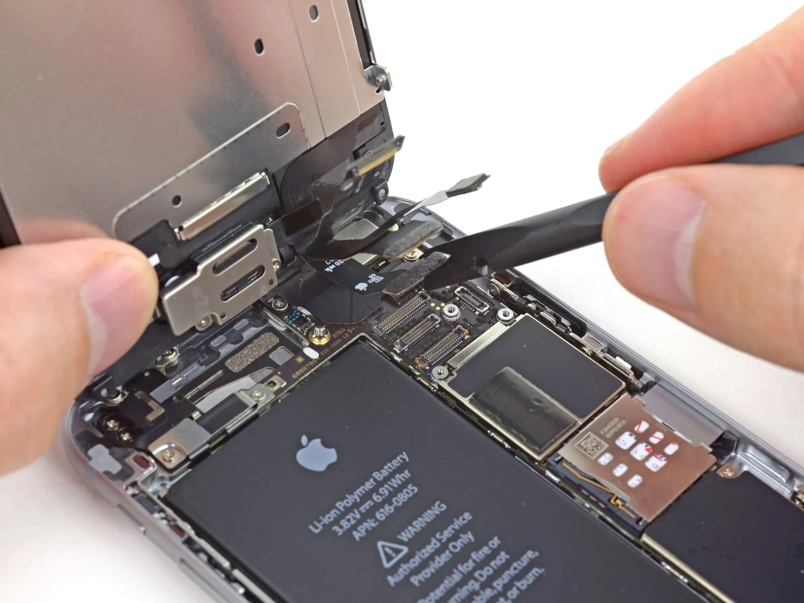
When proceeding with the following four actions, ensure that lifting force is applied solely to the cable connectors themselves, avoiding any upward pressure on the corresponding sockets located on the logic board.
Carefully detach the front camera and sensor cable connector from its socket using a spudger or similar tool.
Carefully detach the front camera and sensor cable connector from its socket using a spudger or similar tool.
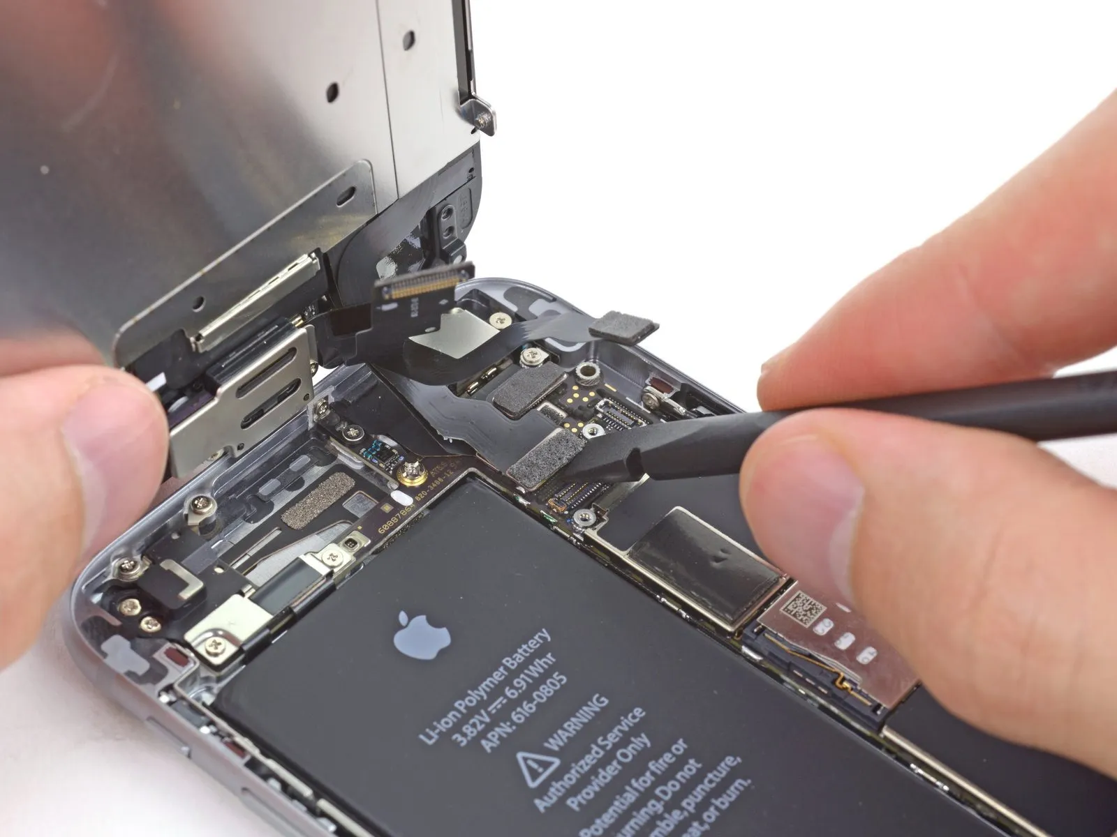
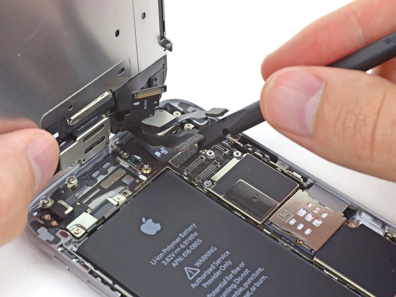
Step 15
Carefully detach the home button cable connector using a spudger or fingernail.
Step 16
Prior to either detaching or reattaching the cable in this procedure, ensure the battery is disconnected.
Carefully detach the display data cable connector using a spudger or fingernail.
Should the display data cable become detached from its connector during reassembly, a blank screen or white lines may appear upon powering on the device; to resolve this, reattach the cable and restart the phone, preferably by disconnecting and reconnecting the battery connector.
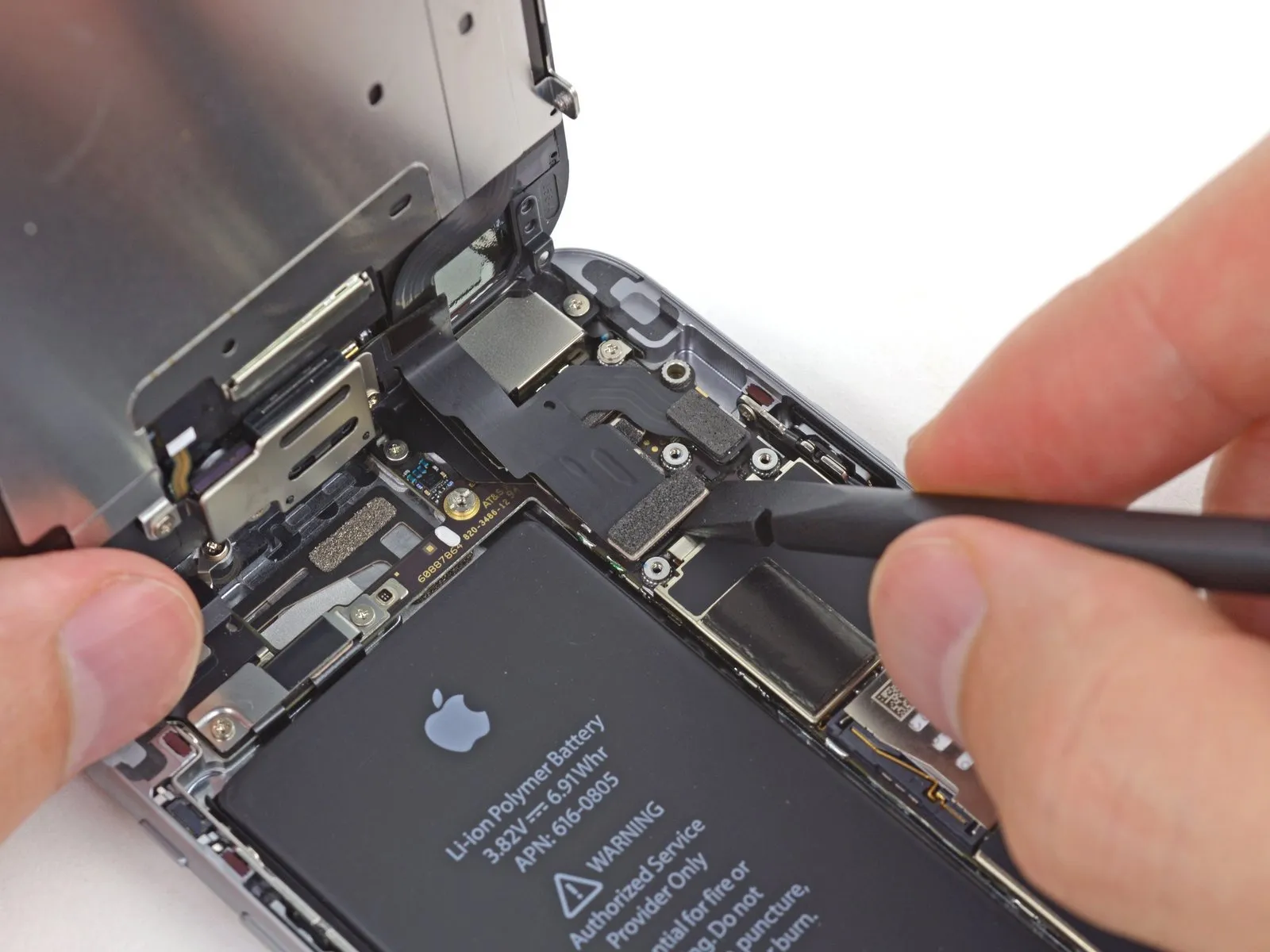
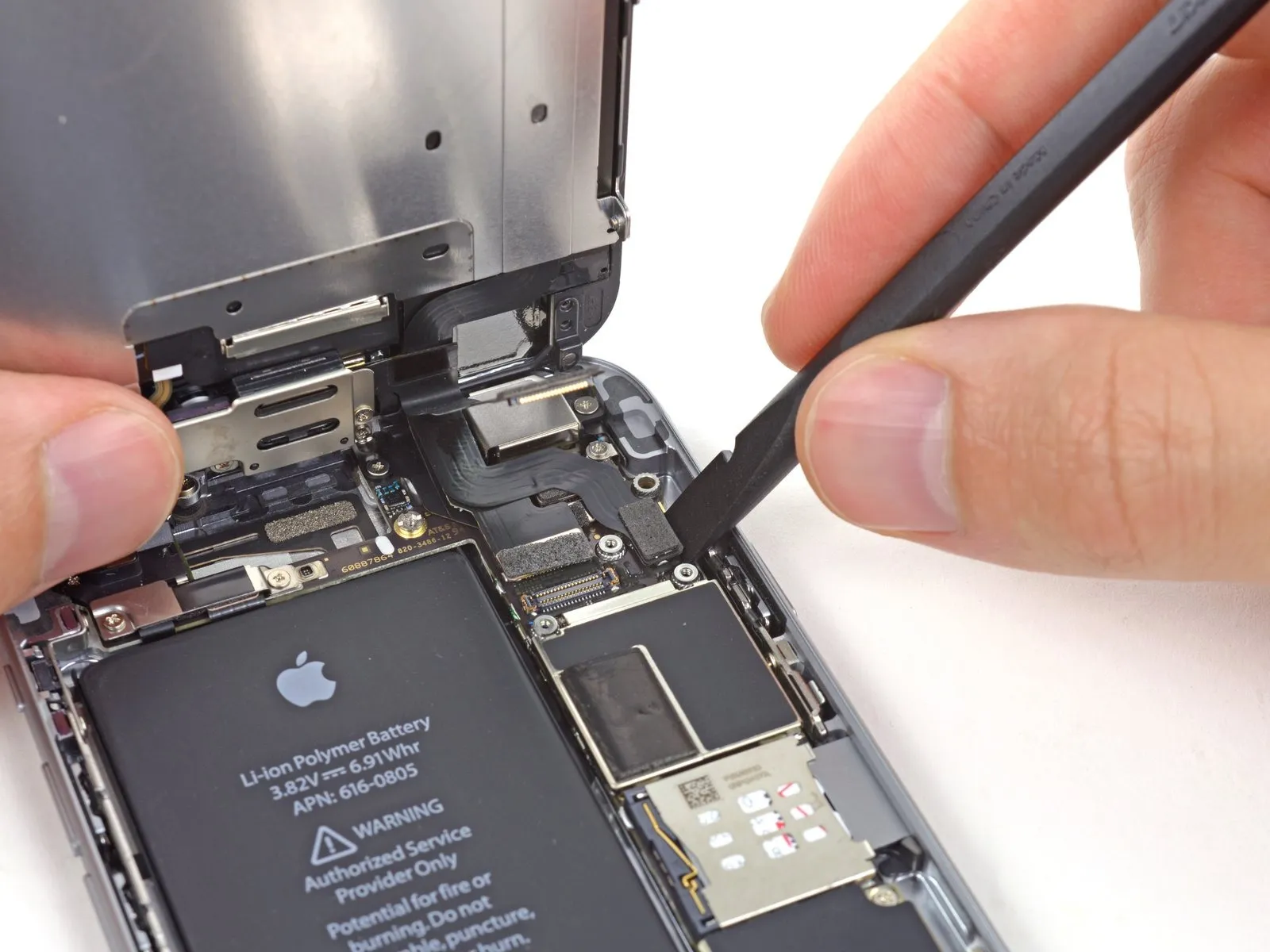
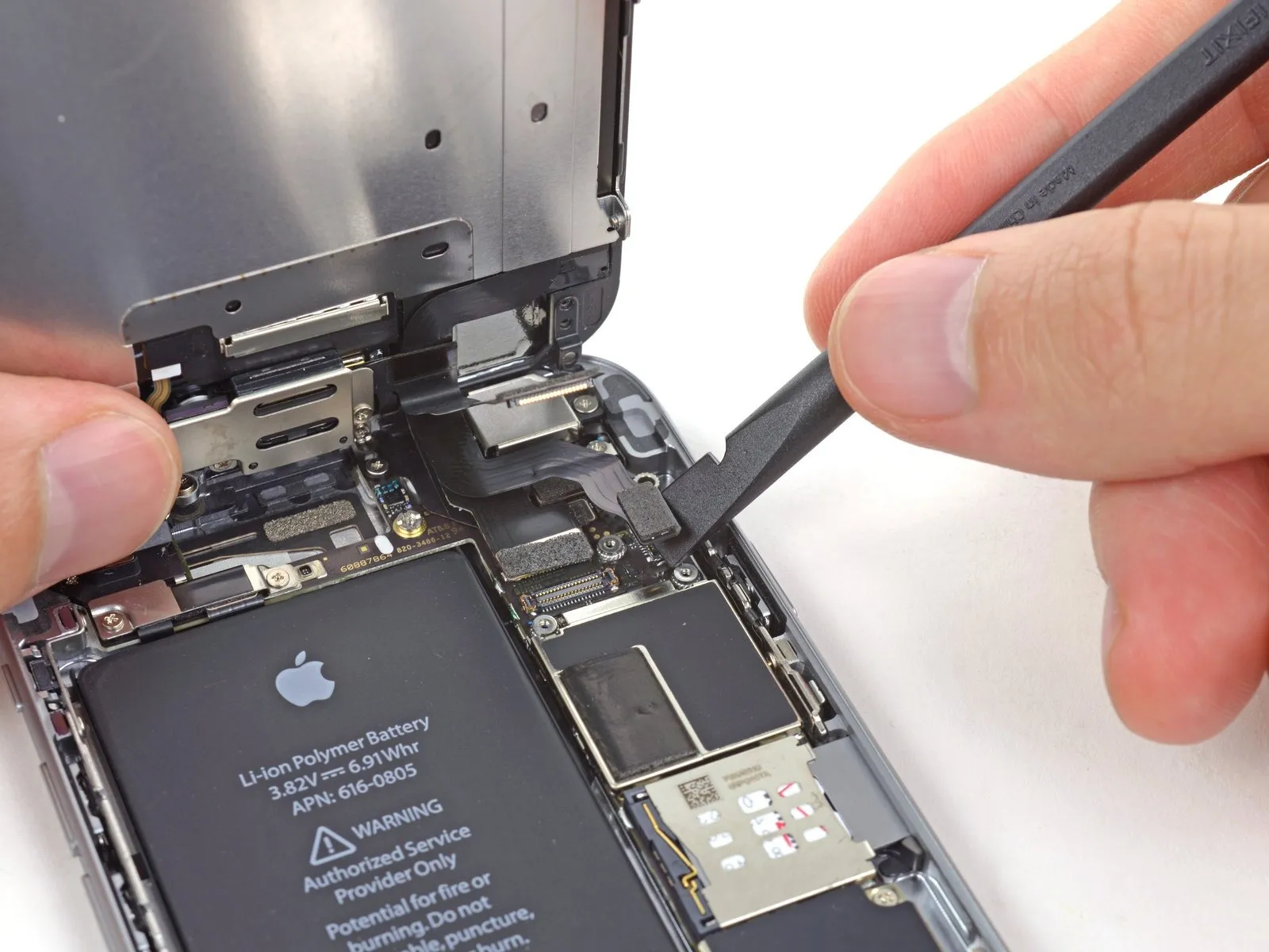
Step 17

Carefully separate the digitizer cable connector from its socket using the flat tool end of a spudger.
To avoid potential damage to the digitizer, ensure the connector is properly seated by applying pressure to its opposing ends, rather than the central portion; central pressure can deform the component.
To avoid potential damage to the digitizer, ensure the connector is properly seated by applying pressure to its opposing ends, rather than the central portion; central pressure can deform the component.
Step 18 | Separating front panel assembly and rear case

Detach the front panel assembly from the rear case.
Step 19 | SIM Card


Using a SIM card eject tool or a straightened paperclip, gently push into the tiny aperture located on the SIM card tray to release it.
Apply force to release the tray from its housing.
Applying considerable pressure might be necessary.
Apply force to release the tray from its housing.
Applying considerable pressure might be necessary.
Step 20
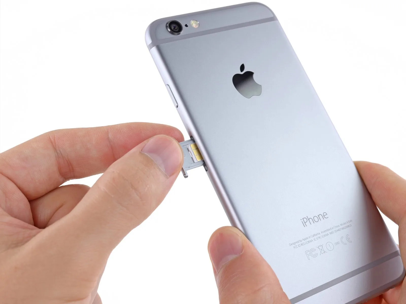
Using a SIM ejection tool or a small, sturdy paperclip, carefully release the SIM card tray and extract it from the iPhone.
Confirm the SIM card's correct alignment within the tray before sliding it back into the device.
Confirm the SIM card's correct alignment within the tray before sliding it back into the device.
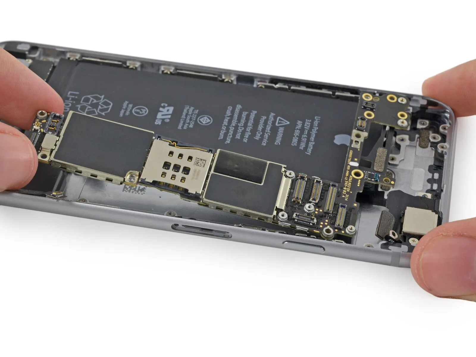
Step 21 | Logic Board
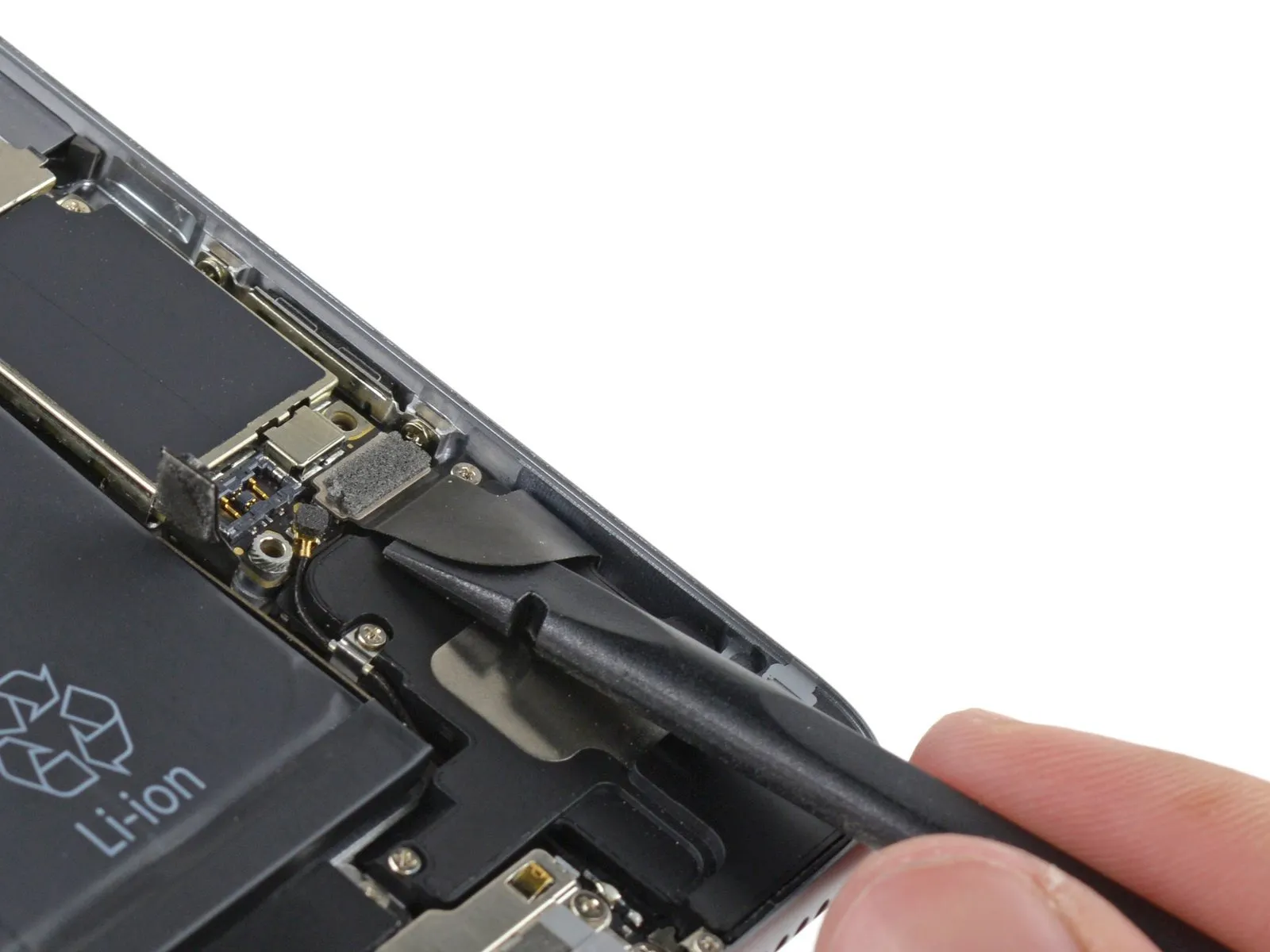

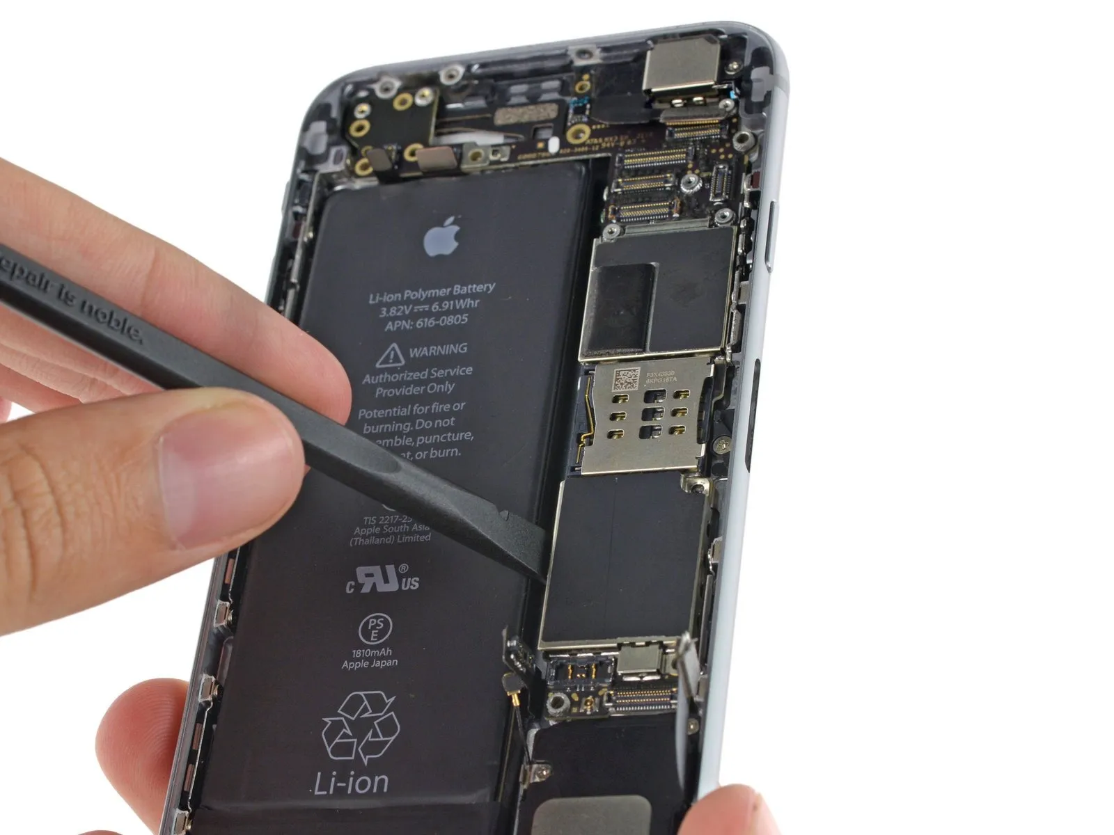
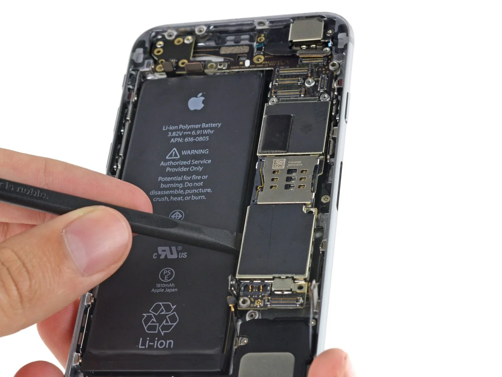
Carefully detach the Lightning connector assembly cable from its socket using the flat spudger, then maneuver it aside to avoid interference with the speaker.
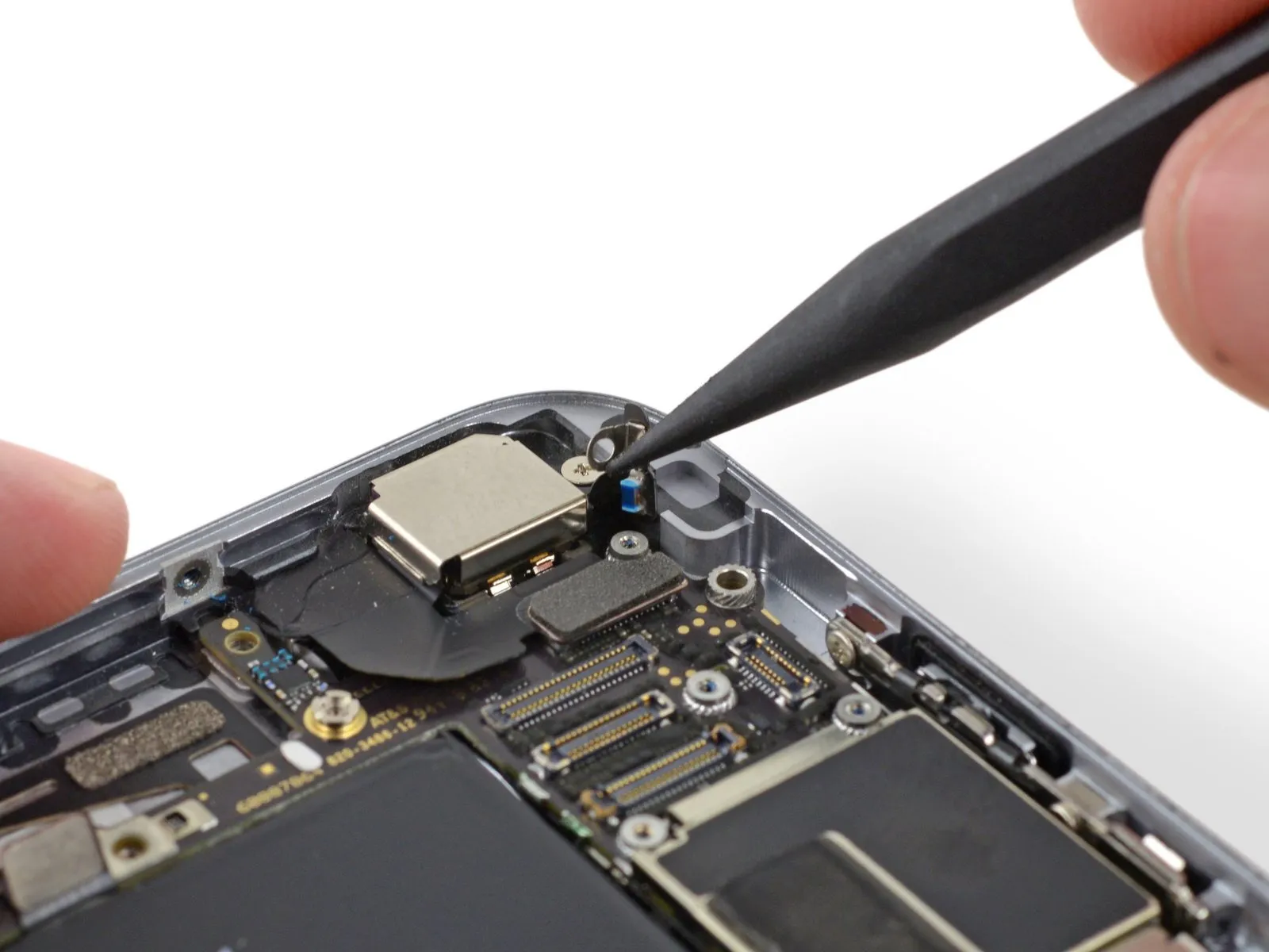
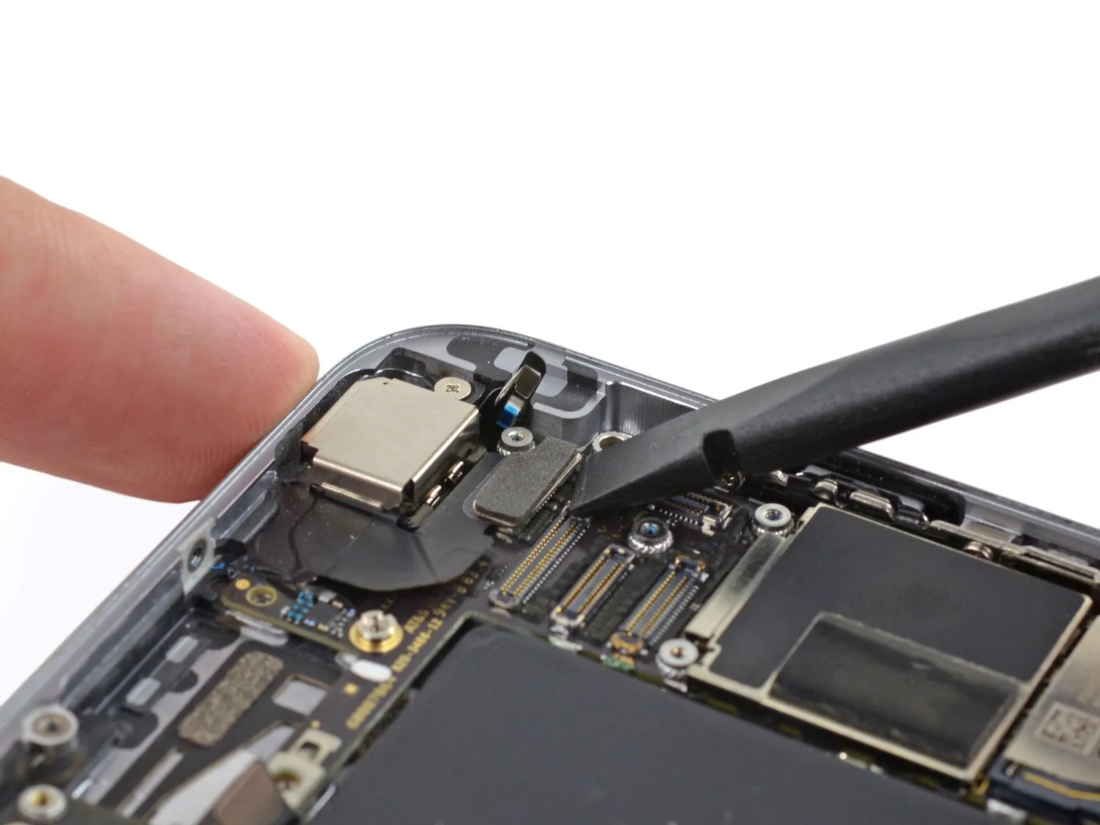
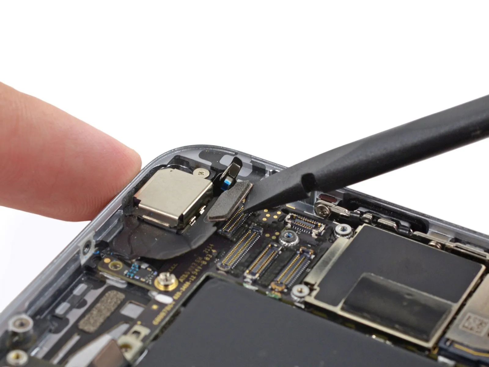
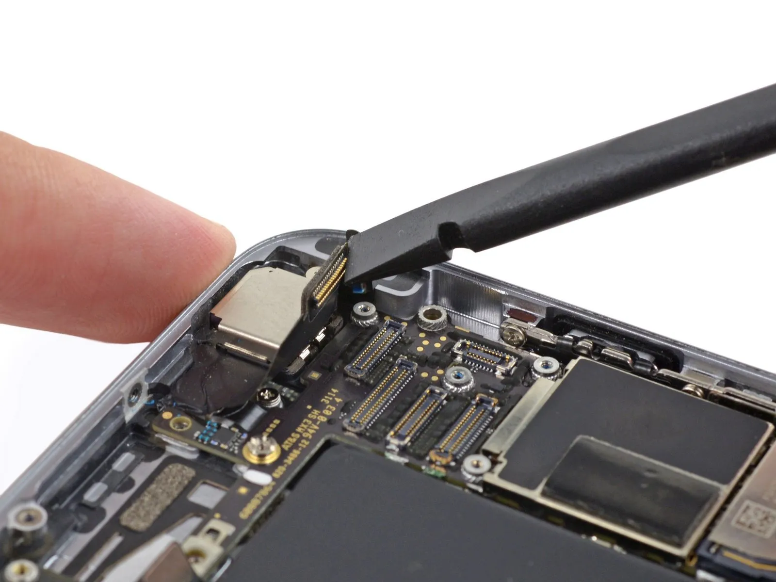
Step 22

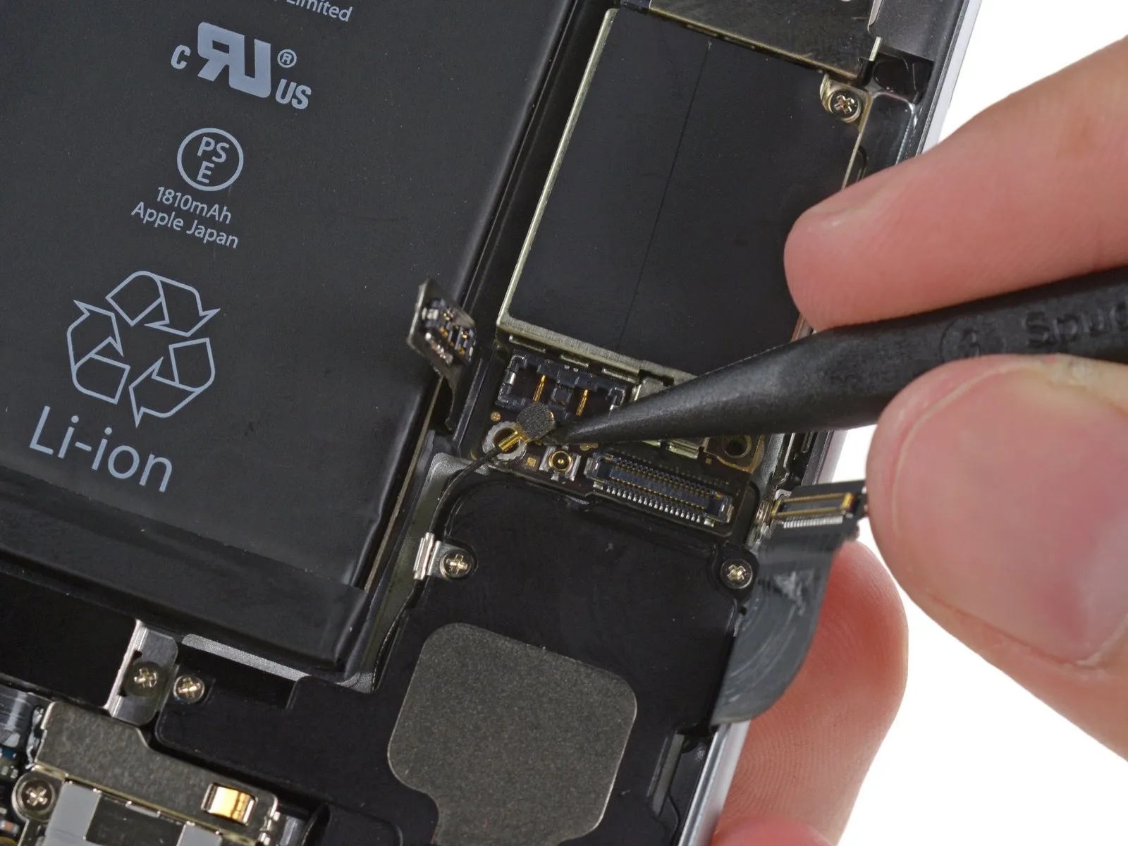
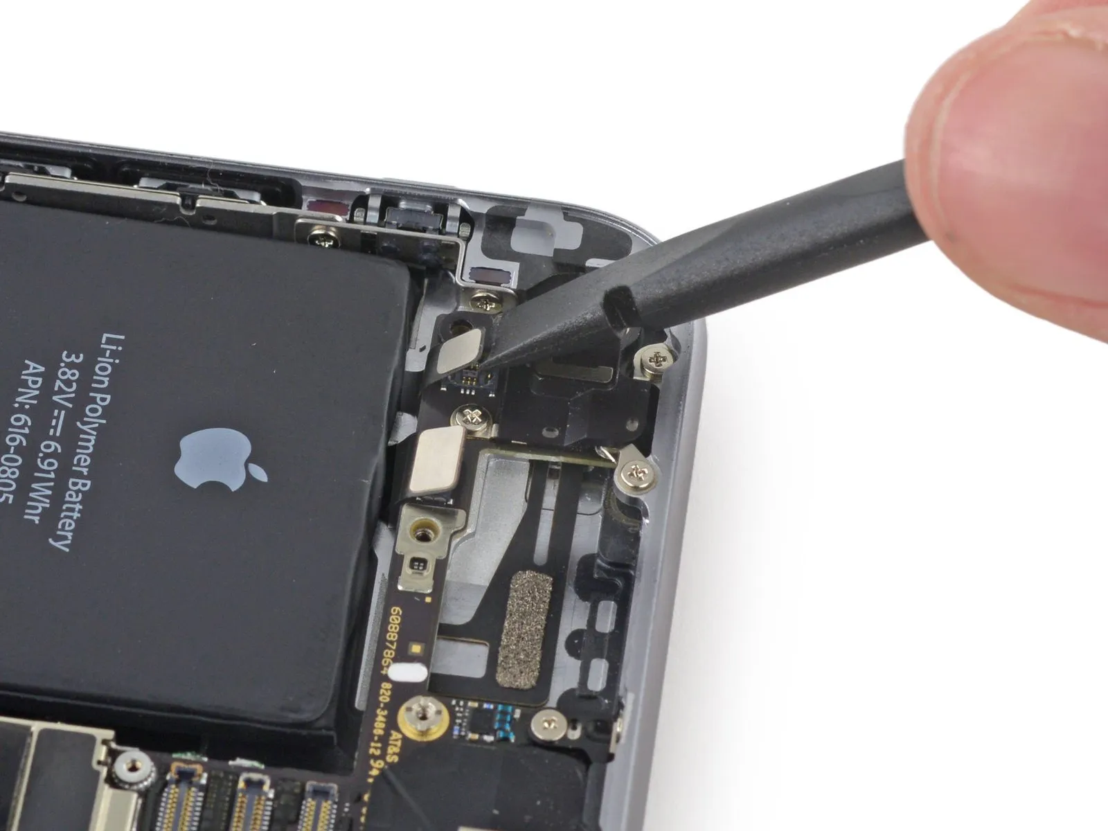
Carefully pry the antenna cable connector away from its socket on the logic board using a spudger tip.
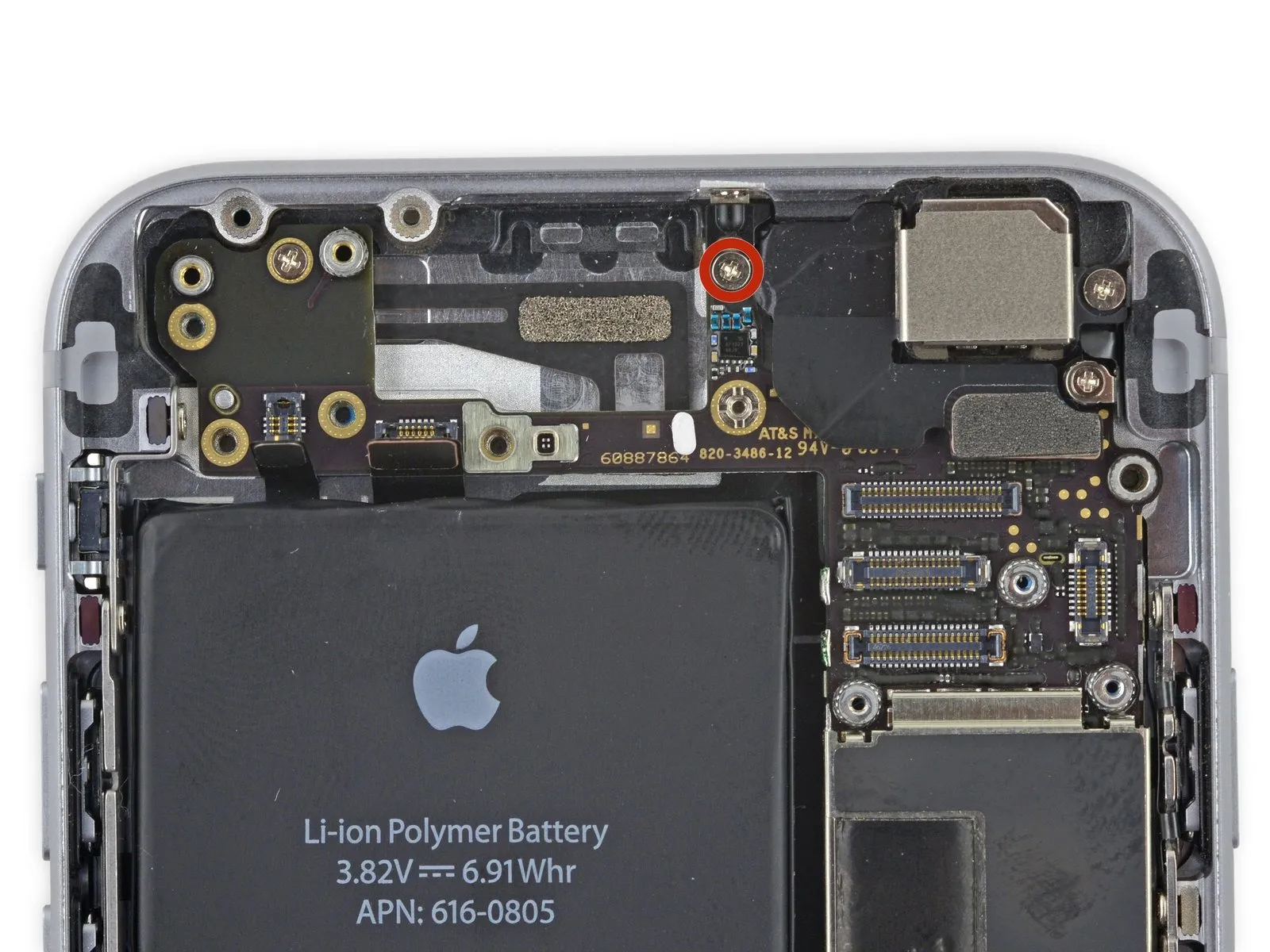
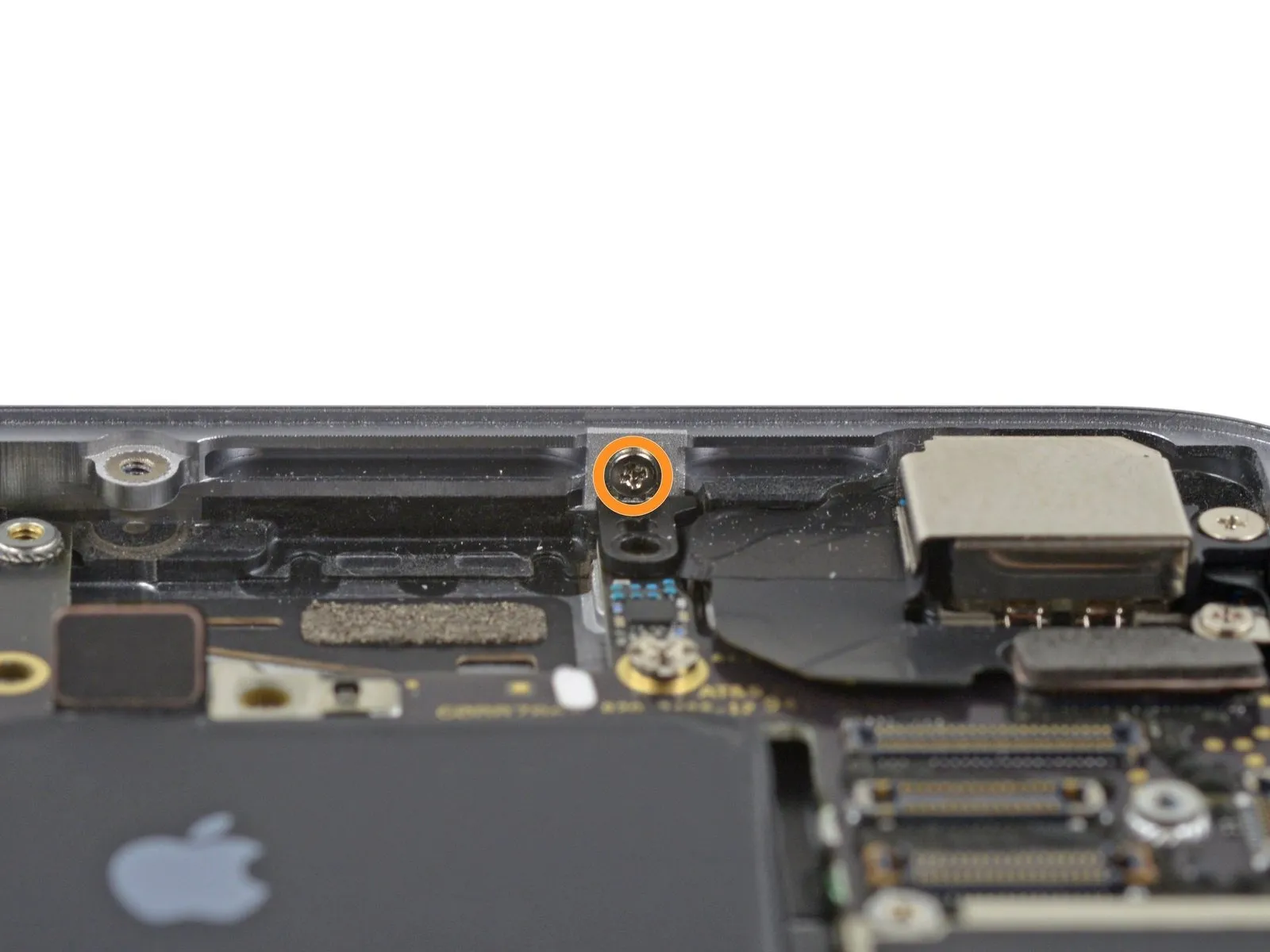
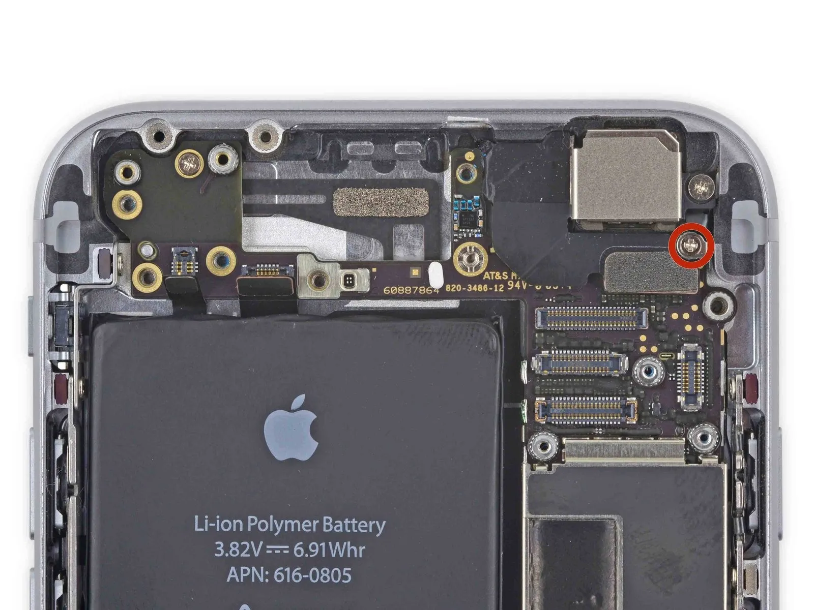
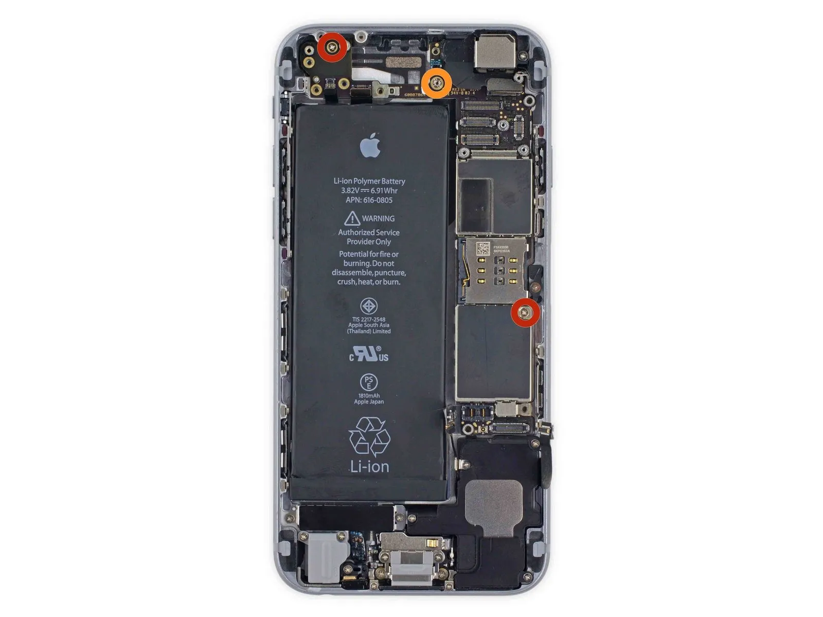
Step 23
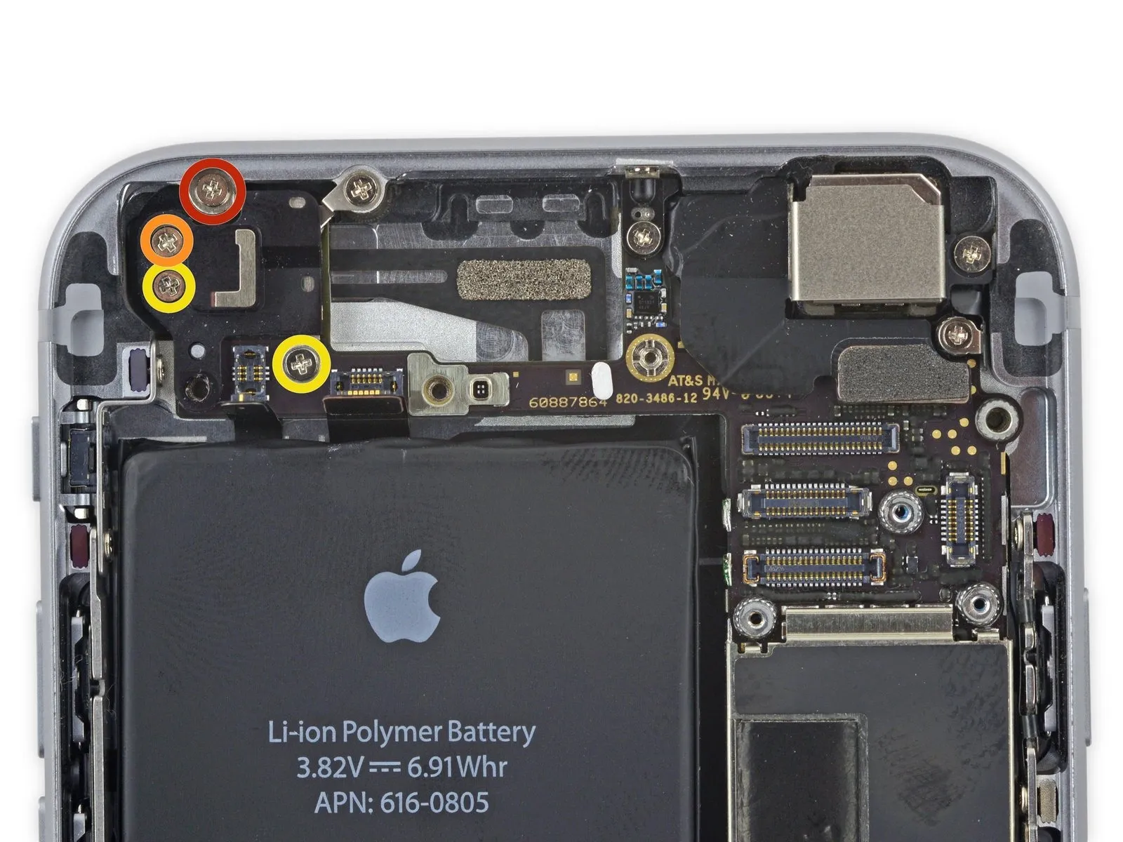
Using a Phillips screwdriver, detach the upper cable bracket by unscrewing the included fasteners.
A screw with a 2.9 mm diameter is required.
A screw with a 2.2-millimeter head diameter is required.
A screw with a 2.9 mm diameter is required.
A screw with a 2.2-millimeter head diameter is required.
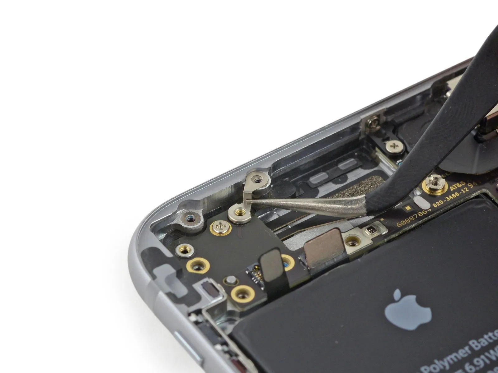
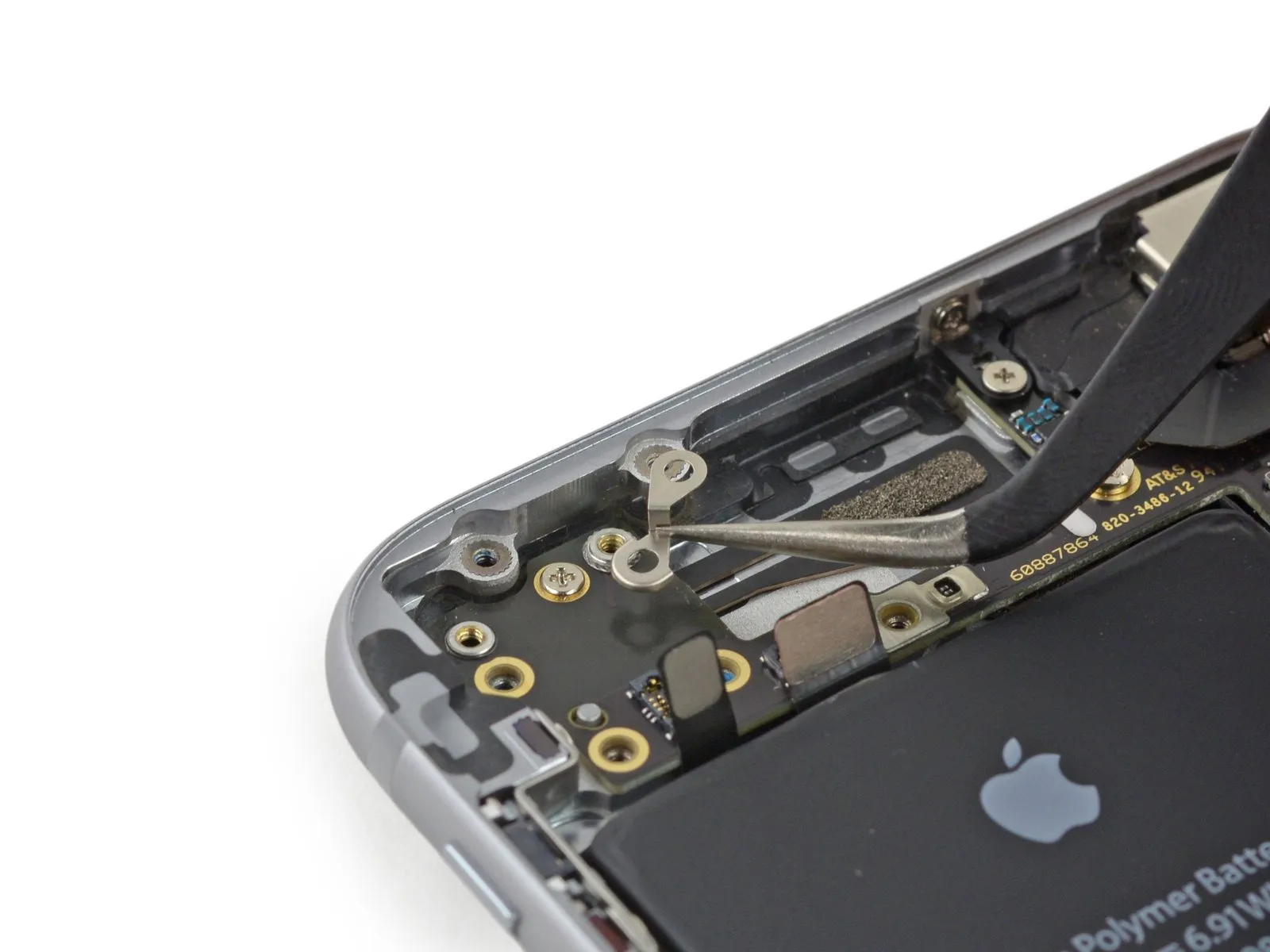
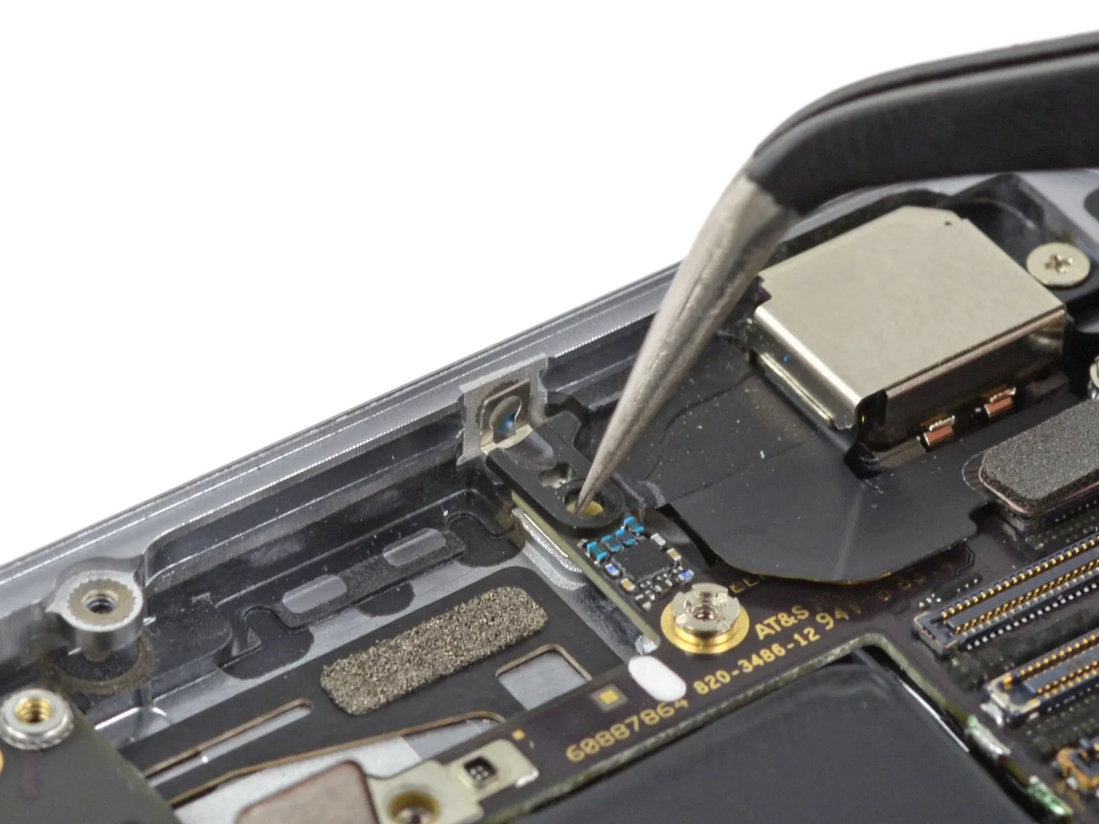
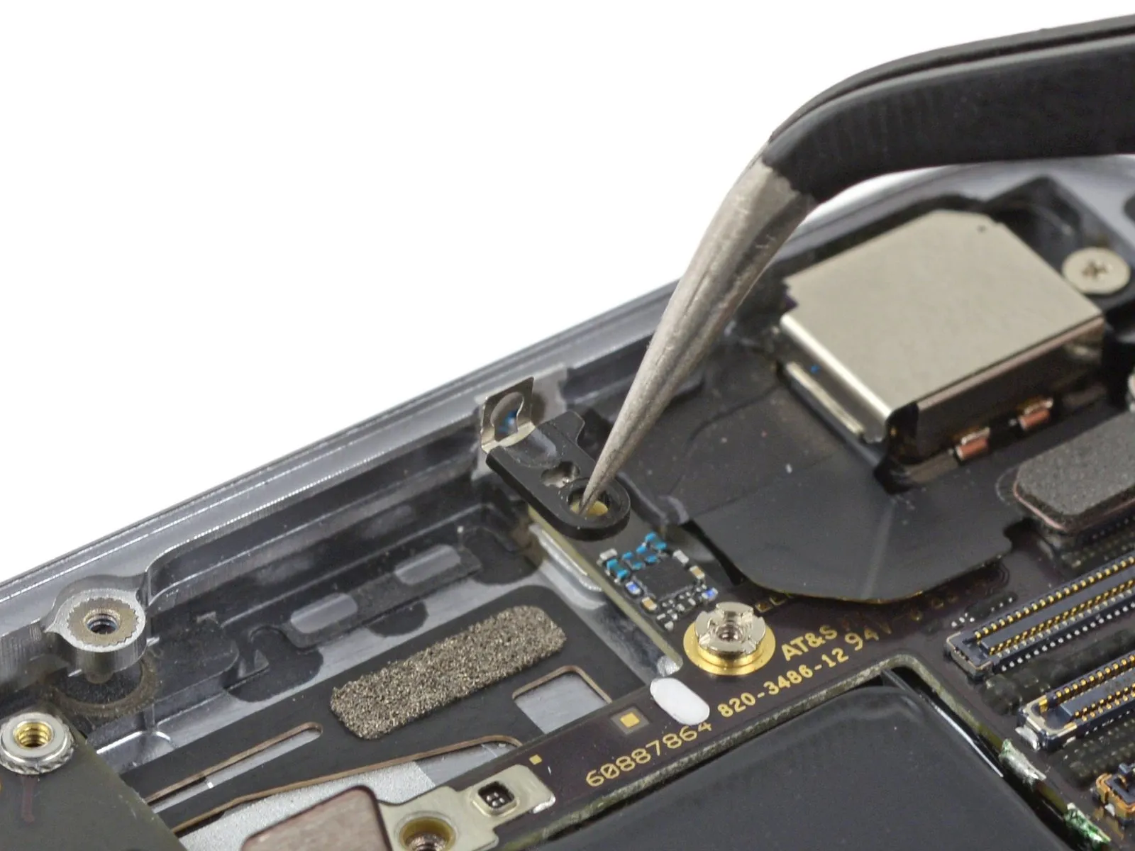
Step 24
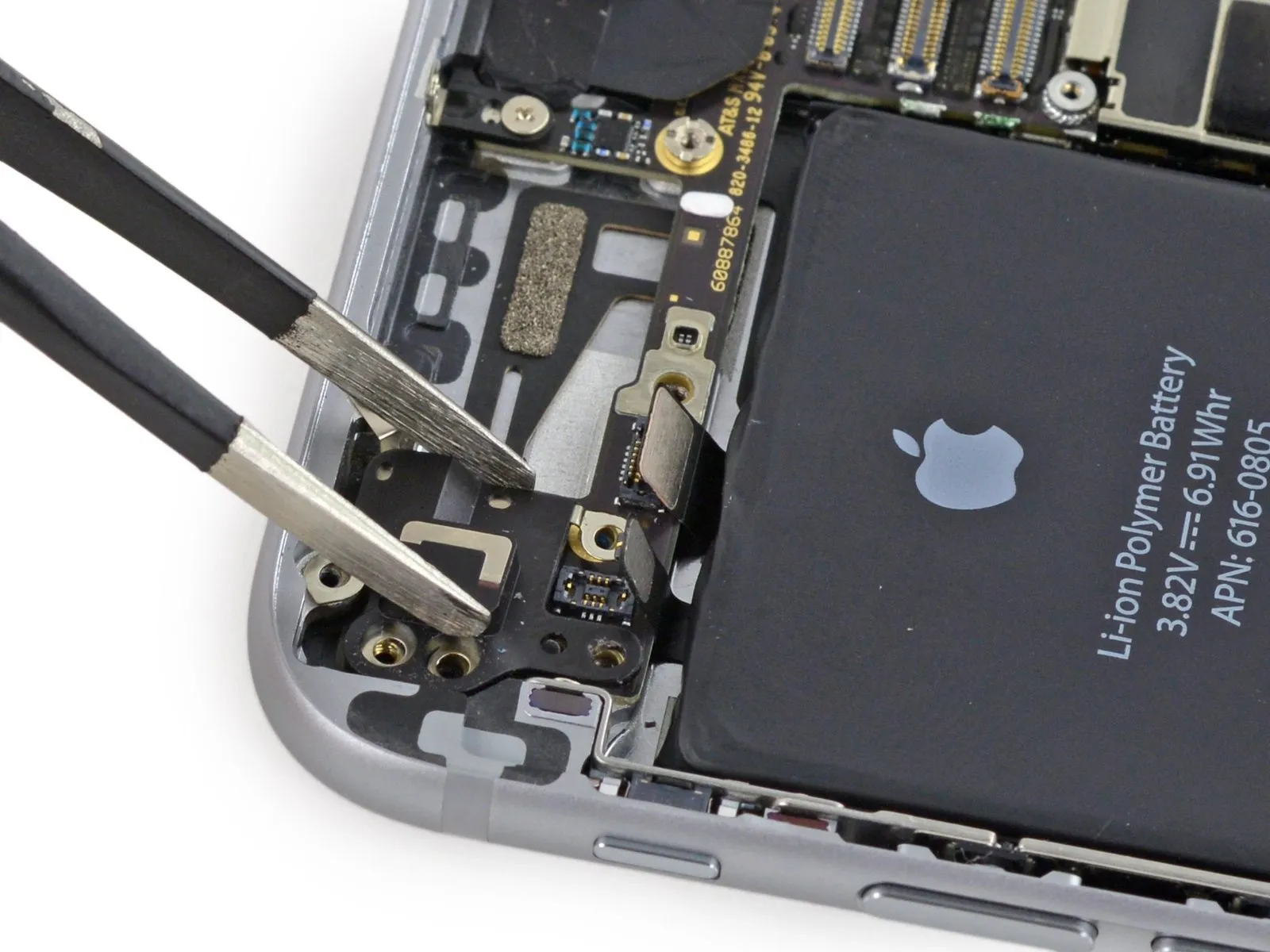
Detach the iPhone's upper cable securing bracket.
Step 25

To avoid irreversible harm to the logic board, carefully separate connectors by applying upward force solely to the connector body itself, never the socket it connects to.
Employing the flat spudger tip, carefully disengage the power button and flash assembly cable connector from its socket.
Carefully detach the volume control cable connector from its corresponding socket on the logic board.
Employing the flat spudger tip, carefully disengage the power button and flash assembly cable connector from its socket.
Carefully detach the volume control cable connector from its corresponding socket on the logic board.
Step 26
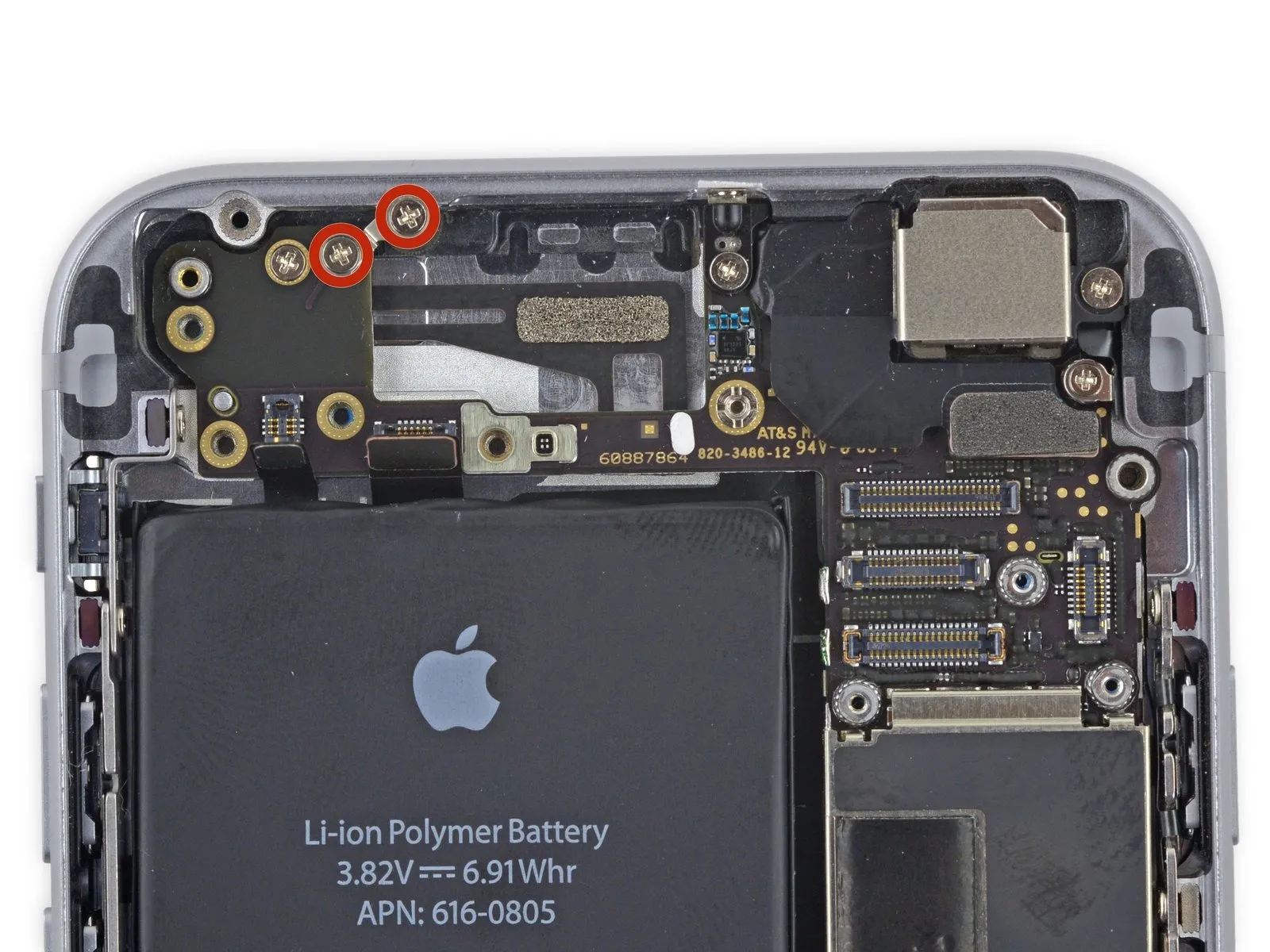
Using a Phillips screwdriver, detach the four screws securing the Wi-Fi antenna.
- A screw with a 1.5 mm head diameter is required.
- A screw with a 1.4-millimeter diameter is required.
- Use two screws, each measuring 2.1 millimeters.
Step 27

Carefully detach the Wi-Fi antenna assembly from the iPhone.
To prevent conductivity issues caused by oils from your skin, avoid direct contact with metal-to-metal interfaces; instead, utilize tweezers or gloves. Should contact occur, thoroughly clean those areas with a degreaser, such as Windex or isopropyl alcohol, prior to reassembling the device.
To prevent conductivity issues caused by oils from your skin, avoid direct contact with metal-to-metal interfaces; instead, utilize tweezers or gloves. Should contact occur, thoroughly clean those areas with a degreaser, such as Windex or isopropyl alcohol, prior to reassembling the device.
Step 28
Using a Phillips screwdriver, detach the grounding bracket by unscrewing the pair of 1.6 mm screws securing it.
Step 29
Detach the iPhone's grounding bracket.
Step 30
Using a Phillips screwdriver, detach the angled logic board bracket by unscrewing the screws that hold it in place.
- A screw with a 2.6-millimeter head diameter is required.
- A single 1.3 mm screw is situated within the iPhone's upper sidewall, oriented horizontally.
Step 31
Using a Phillips head screwdriver, detach the angled bracket securing the logic board.
Step 32
Using a Phillips screwdriver, detach the antenna interconnect cable from the logic board by unscrewing the 1.2 mm screw that holds it in place.
Step 33

Carefully maneuver the antenna interconnect cable, using a spudger tip to gently lift and position it clear of the logic board.
Step 34
Employing the flat spudger tip, carefully disengage the camera cable connector by applying upward pressure to remove it from its corresponding socket on the logic board.
To prevent irreversible harm to the logic board, apply prying force exclusively to the connector, avoiding contact with the socket.
To allow access to the logic board, carefully maneuver the camera cable so it is positioned away from the work area.
To prevent irreversible harm to the logic board, apply prying force exclusively to the connector, avoiding contact with the socket.
To allow access to the logic board, carefully maneuver the camera cable so it is positioned away from the work area.
Step 35
Using the appropriate screwdriver, detach the logic board from the rear case by unscrewing the listed fasteners.
Use two Phillips screws, each measuring 1.9 mm.
A screw with a 2.3 mm diameter is required.
To detach standoff screws, utilize a standoff screwdriver or a compatible bit.
If a dedicated tool isn't available, a small flathead screwdriver can be carefully employed; however, exercise heightened awareness to prevent slippage and potential harm to nearby parts.
Step 36
Carefully align the 4mm diameter dowel pins with their corresponding holes in both the upper and lower chassis halves, then gently press the two sections together until fully seated, ensuring no gaps remain and the assembly is flush.
Carefully elevate the logic board's battery connector end a small amount—sufficient for fingertip grasping—by employing the flat spudger tip.
To prevent chip or socket damage, use the spudger to carefully access the metal shields situated beneath the SIM card tray.
Carefully elevate the logic board's battery connector end a small amount—sufficient for fingertip grasping—by employing the flat spudger tip.
To prevent chip or socket damage, use the spudger to carefully access the metal shields situated beneath the SIM card tray.
Step 37
Carefully align the 4mm diameter dowel pins, ensuring they are fully seated within the corresponding holes on both the upper and lower chassis sections, then secure the assembly with the provided M3x6 screws using a 2mm hex key, observing the torque specification of 4.5 Nm and paying close attention to the warning regarding potential damage to the threads if over-tightened.
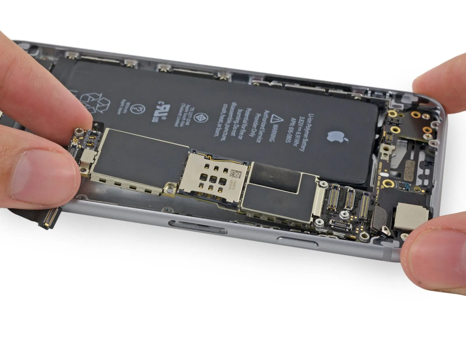
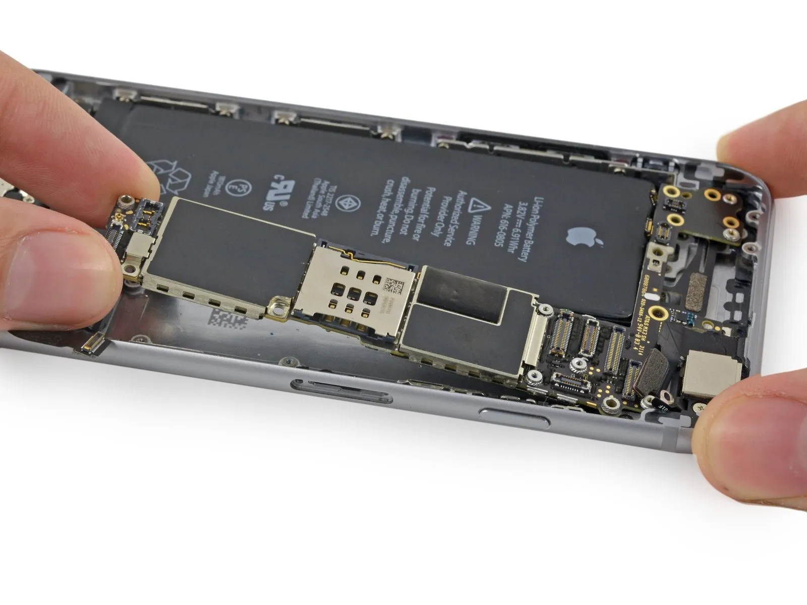
Carefully raise the logic board’s battery connector end, then disengage it from the rear case by pulling upwards.
Exercise caution to prevent the logic board from being damaged by contact with any wires.
Carefully raise the logic board’s battery connector end, then disengage it from the rear case by pulling upwards.
Exercise caution to prevent the logic board from being damaged by contact with any wires.
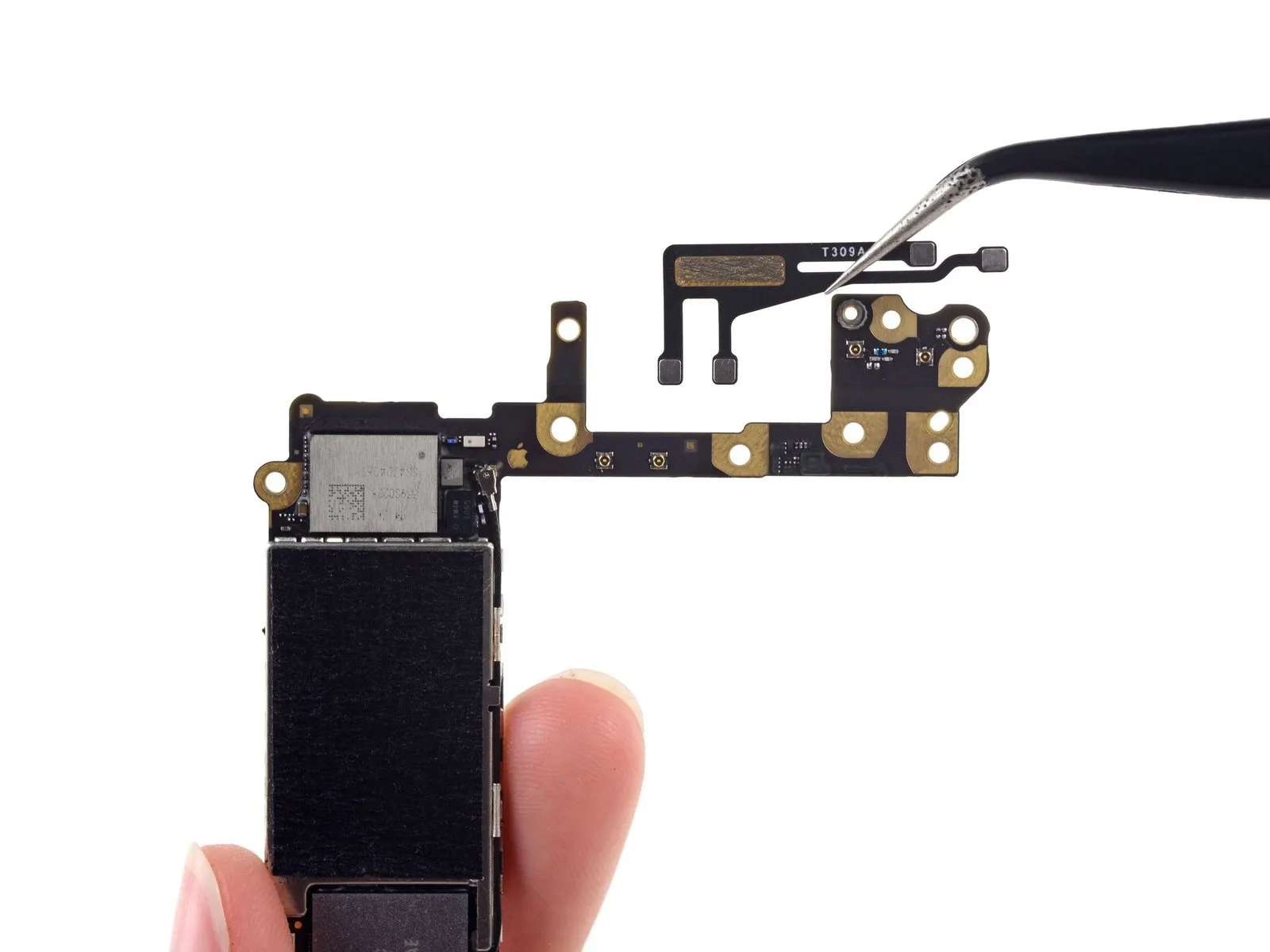
Step 38 | Antenna Flex Cable

Using a 5/32-inch hex key, carefully tighten the four M4x8 screws securing the fan assembly to the heatsink, ensuring a torque of 4.5 in-lbs to prevent damage.
To access the antenna located on the rear surface, rotate the logic board so that the opposite side faces upward.
Carefully detach the four coaxial connectors and the antenna cable, all of which are connected to the logic board.
To prevent conductivity issues caused by oils from your skin, avoid direct contact with metal-to-metal interfaces; utilize tweezers or gloves instead. Should contact occur, thoroughly clean those areas with a degreaser, such as Windex or isopropyl alcohol, prior to reassembling the device.