iPhone 5s Home Button Replacement
This document details the procedure for substituting the iPhone 5s home button assembly.
- The Touch ID feature is exclusive to the factory-supplied home button assembly; replacement with a non-original part will result in standard home button operation only, without Touch ID capability.
This document also provides instructions for substituting these components.
Step 1 | Removing the Pentalobe screws

Begin the process by ensuring the 1/4-inch hex key is used to loosen the four retaining screws securing the fan assembly, then carefully detach the fan, observing the 12V power connector's orientation for reassembly.
To prevent potential fire or explosion hazards during the repair process, ensure the iPhone's lithium-ion battery is depleted to less than 25% capacity beforehand; a fully charged battery poses a significant risk of ignition or rupture if damaged.
To prevent electrical shock or damage, ensure the iPhone is completely de-energized prior to starting the repair process.
Using a Pentalobe screwdriver, detach the two screws, each measuring 3.9 mm, located on the left and right sides of the Lightning connector.
Step 2 | Taping the display glass


Using a 5/32-inch hex key, carefully loosen the four screws securing the fan assembly to the motor housing; be aware that the screws may be tight and require firm pressure, but avoid excessive force to prevent stripping the screw heads.
To mitigate the risk of additional shattering and potential injury while repairing a cracked display glass, secure it with tape.
Completely cover the iPhone screen with overlapping strips of clear packing tape, ensuring full surface protection.
To prevent glass fragments from scattering and maintain stability during the display separation process, this technique is essential.
To safeguard your eyes from potential glass fragments that may detach during the repair process, it is essential to use safety glasses.
Step 3 | Display separation prevention


Using a 5/32-inch hex key, carefully tighten the retaining screw on the motor assembly to a torque of 3.5 Nm, ensuring the motor shaft aligns correctly and avoiding damage to the threads.
Carefully lift the display assembly—consisting of a glass screen, a plastic bezel, and integrated metal clips—from within the phone's chassis during the subsequent procedures.
Ensure complete removal of the display assembly, irrespective of the tool selected.
When the glass and plastic layers detach, referencing the initial image for visual guidance, use a plastic opening tool to carefully insert it into the gap between the plastic frame and the phone's metal chassis, releasing the retaining clips.
To ensure proper closure during reassembly of a phone featuring a detached display bezel, apply a narrow adhesive strip positioned between the plastic bezel and the glass surface.
Step 4 | Anti-Clamp instructions


Using a 5/32-inch hex key, carefully tighten the four mounting screws securing the fan assembly to the motor housing, ensuring each is snug but not over-torqued to prevent damage; observe polarity markings when reattaching the wiring harness.
To simplify the opening process, the following two steps utilize the Anti-Clamp tool, a custom-designed aid; if you do not have this tool, proceed two steps further to find an alternative procedure.
Refer to the included guide for detailed procedures regarding Anti-Clamp operation.
To release the Anti-Clamp's arms, move the blue handle in a rearward direction.
Position the arms so they extend across the iPhone's left or right side.
Affix one suction cup to the front surface of the iPhone, close to the lower edge and directly over the home button, and secure another suction cup to the rear surface in the same relative position.
Apply vacuum by pressing the cups firmly against the surface needing treatment.
To improve the Anti-Clamp's grip if the iPhone's exterior is excessively smooth, apply the provided adhesive pad to generate a more textured holding area.
Step 5


Using a 5/32-inch hex key, carefully tighten the four mounting screws securing the fan assembly to the motor housing, ensuring each is snug but not over-torqued to prevent damage.
To secure the arms, advance the blue handle in the direction indicated.
Rotate the handle fully, completing a 360-degree turn, observing for the point when the cups begin to expand.
Maintain parallel positioning of the suction cups; should misalignment occur, gently release the suction cups’ grip and reposition the arms.
Once sufficient space is created by the Anti-Clamp, slide a prying tool beneath the display.
To ensure adequate separation, reposition the handle by 90 degrees.
Apply adjustments incrementally, limiting each rotation to a maximum of 90 degrees, and pause for several seconds after each adjustment to allow the Anti-Clamp mechanism to function and the process to stabilize.
Step 6 | Manual Opening Procedure

Lacking an Anti-Clamp tool, secure the front panel with a single suction cup for lifting.
Position a suction cup directly on the display surface, situated slightly higher than the home button's location.
Ensure the entire cup makes contact with the screen surface to guarantee a secure seal.
Position a suction cup directly on the display surface, situated slightly higher than the home button's location.
Ensure the entire cup makes contact with the screen surface to guarantee a secure seal.
Step 7 | Start lifting the front panel assembly

Carefully detach the front panel by releasing the retaining clips, then gently separate the phone's housing just enough to access and disconnect the multiple ribbon cables, exercising caution to prevent component damage.
Secure the suction cup directly onto the front panel assembly, positioning it close to the home button.
Using one hand to secure the iPhone, lift the suction cup vertically to gently create a small gap between the front panel's home button area and the rear case.Exercise caution and use steady, even pressure when installing the front panel assembly, as its fit is considerably more snug compared to typical device construction.
Secure the suction cup directly onto the front panel assembly, positioning it close to the home button.
Using one hand to secure the iPhone, lift the suction cup vertically to gently create a small gap between the front panel's home button area and the rear case.
Step 8


Disconnecting the front panel assembly from the rear case should be avoided; several sensitive ribbon cables secure the two components together.
To detach the suction cup, depress the plastic projection to break the airtight seal.
Carefully detach the screen from the device using the suction cup.
To detach the suction cup, depress the plastic projection to break the airtight seal.
Carefully detach the screen from the device using the suction cup.
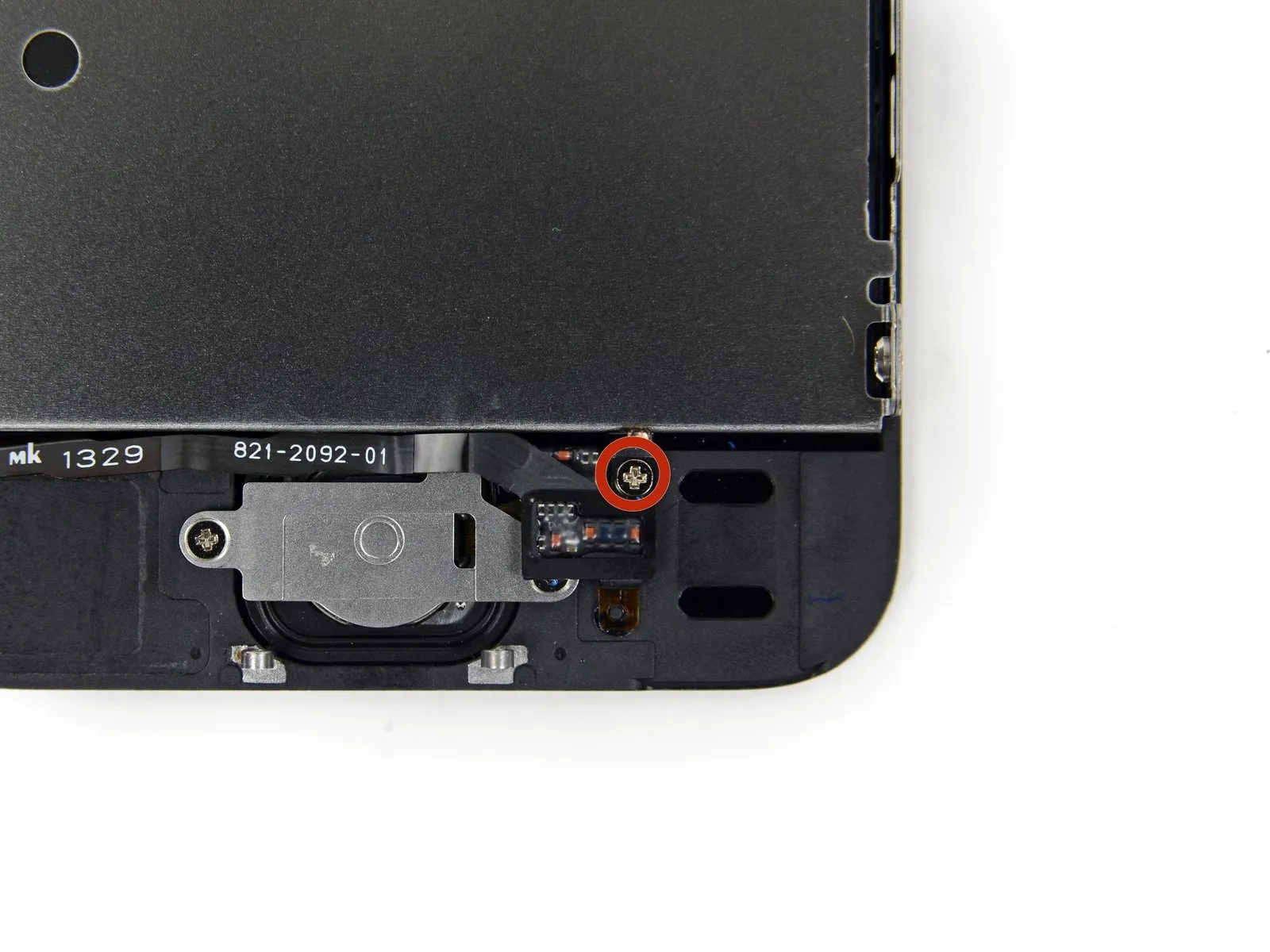
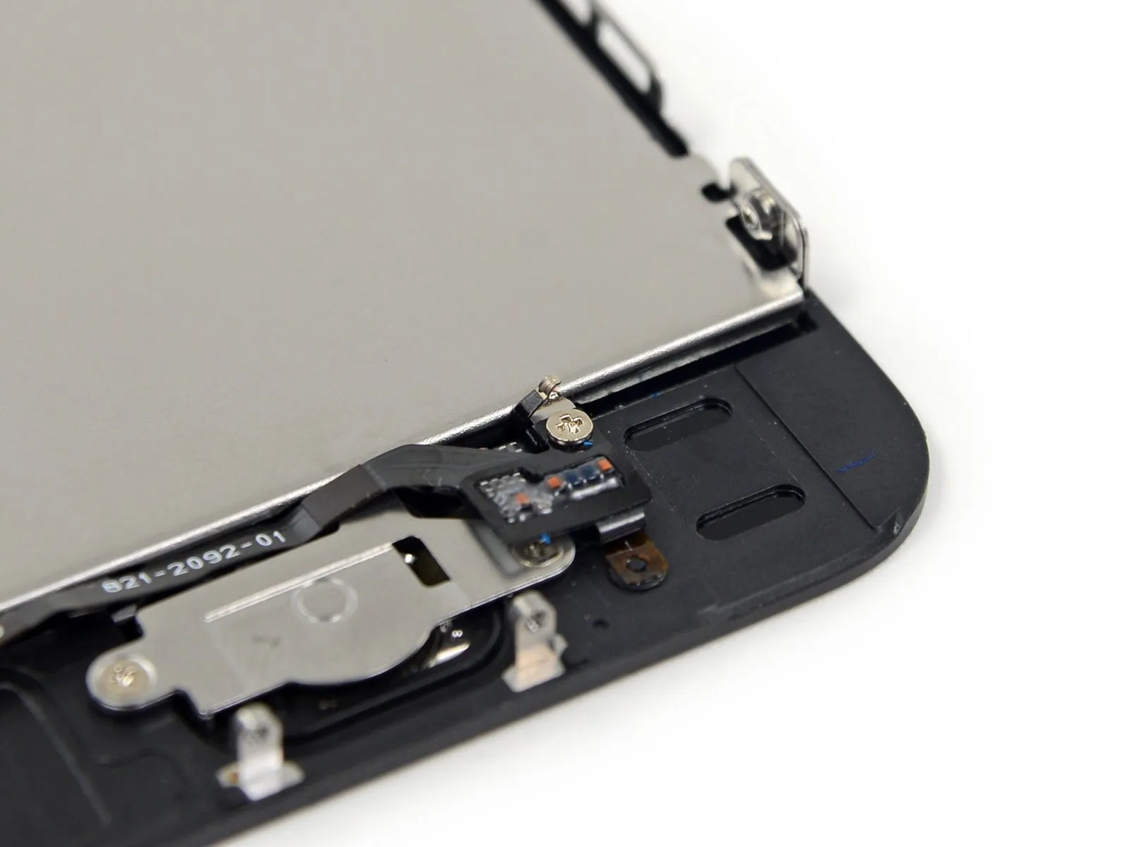
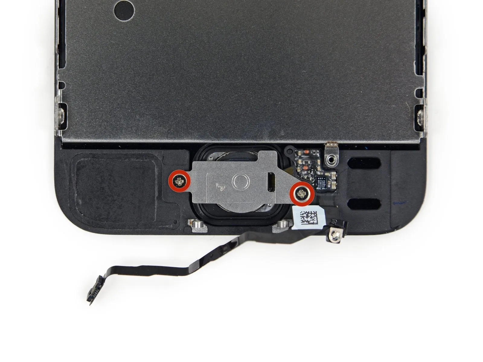
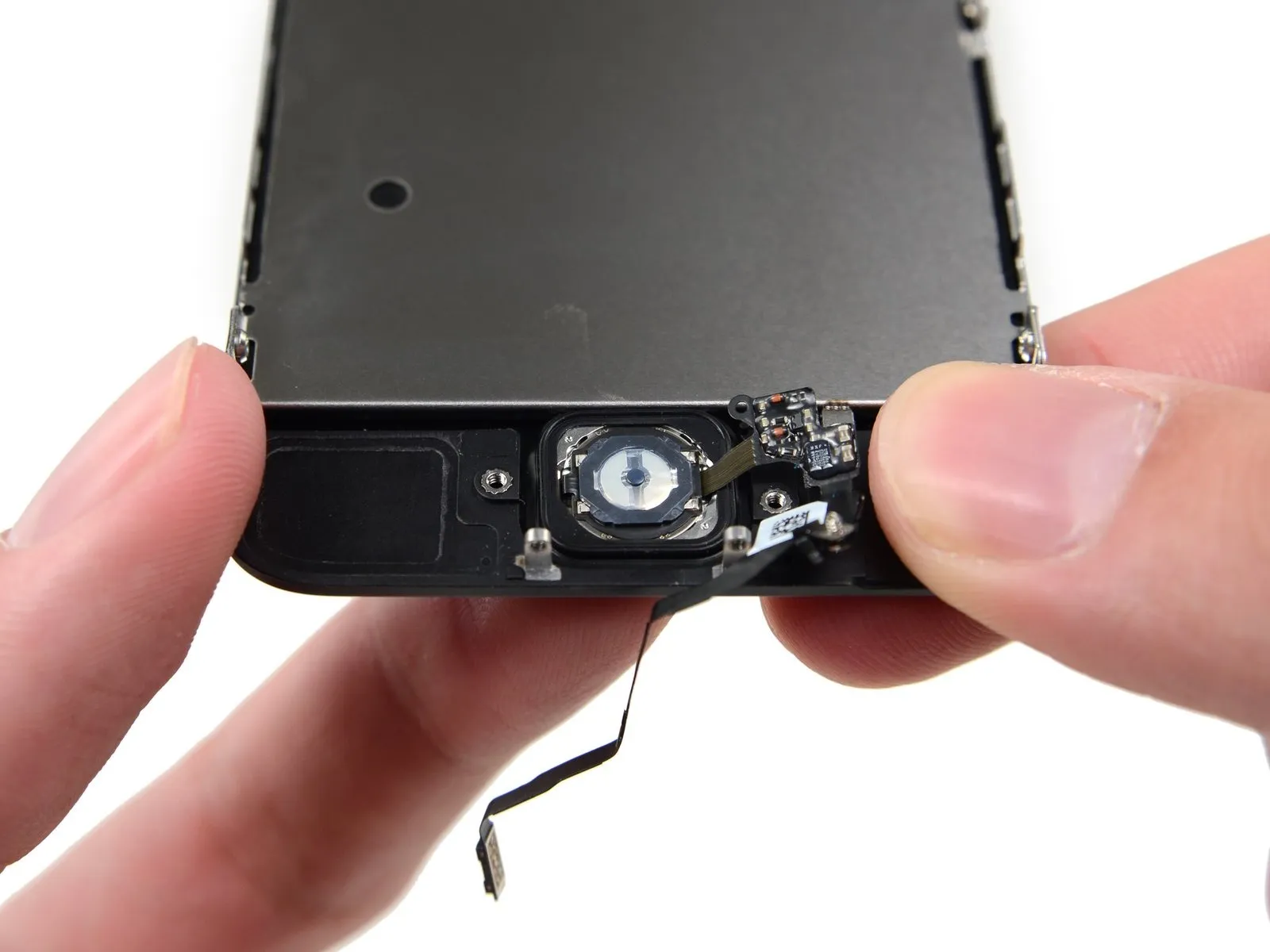
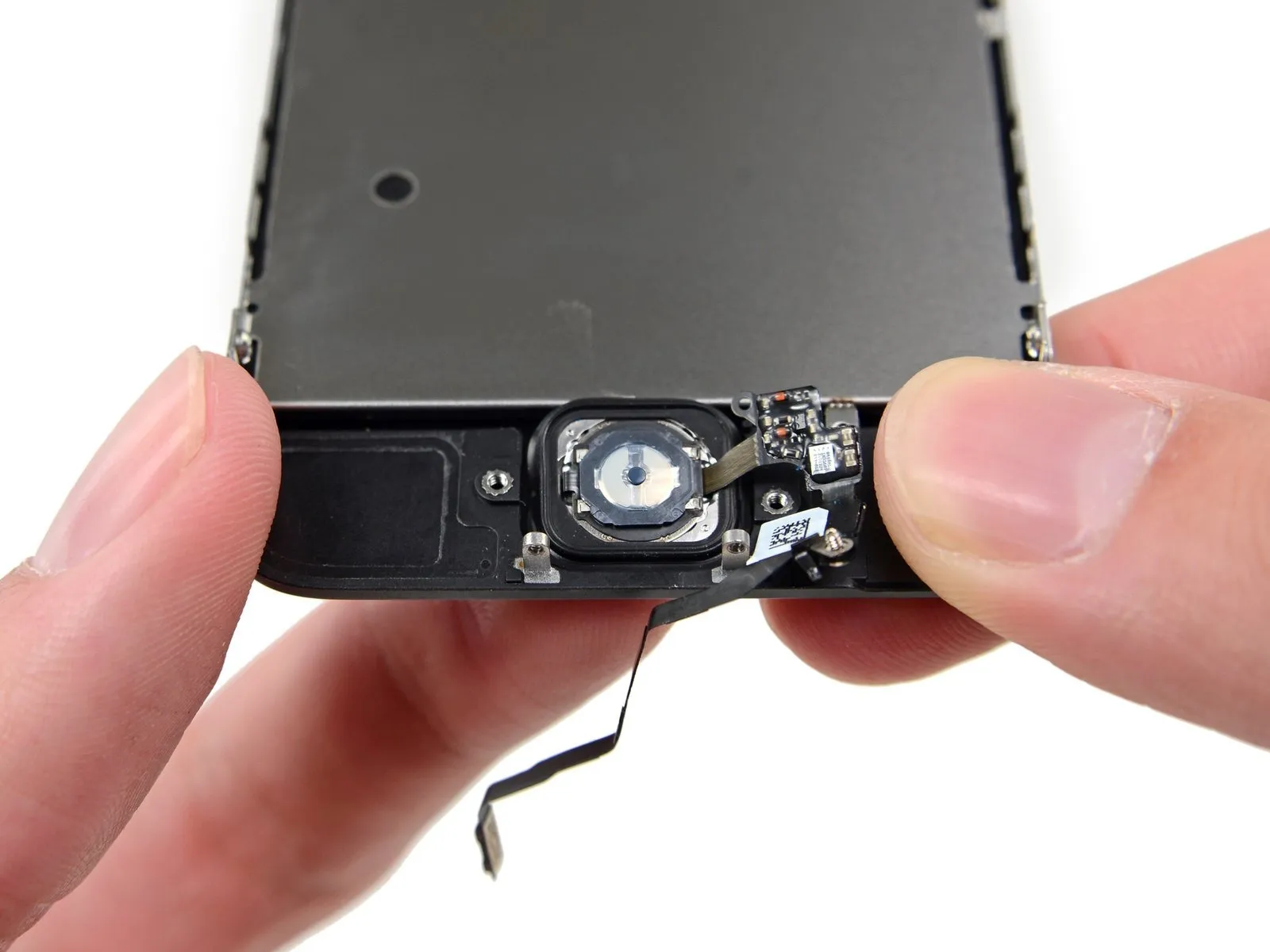
Step 9 | Removing the Touch ID cable bracket


Carefully separate the phone's casing to expose the metallic securing bracket that protects the home button cable.
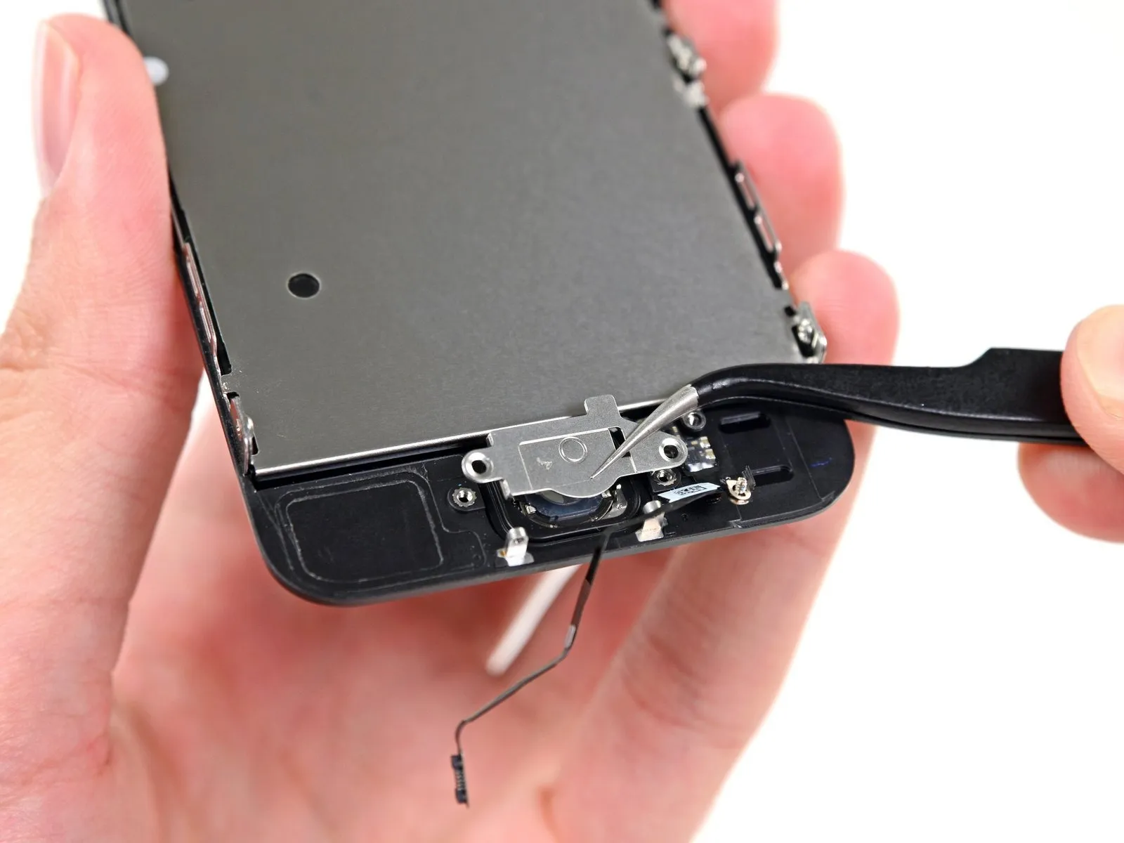
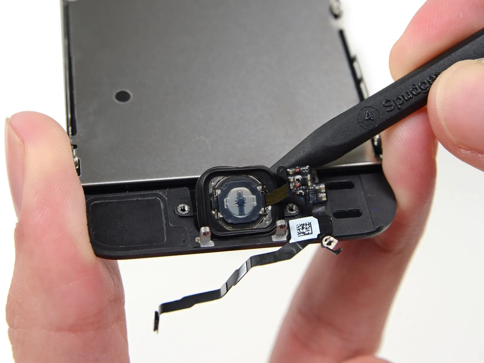
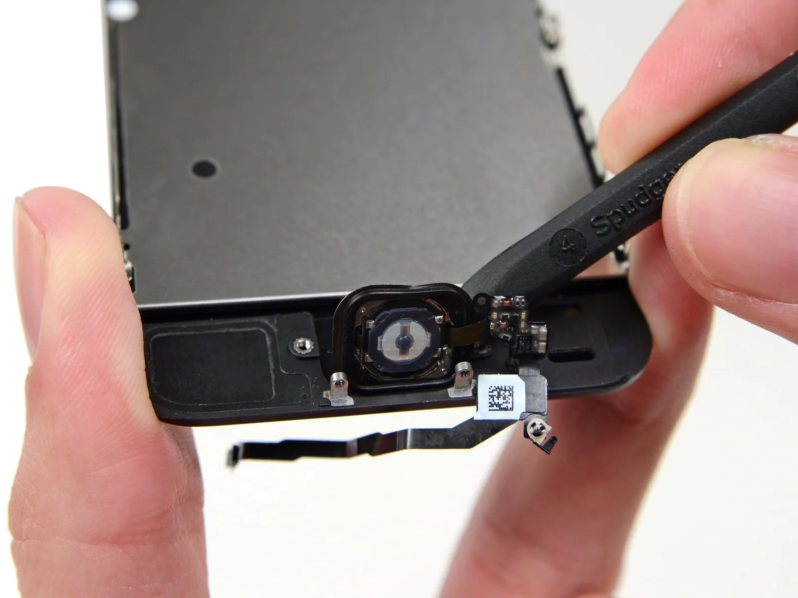
To prevent damage to the home button cable and its connector, avoid excessive separation of the phone's housing; maintain slack in the cable, as overextension can cause harm.Carefully leverage the bracket loose using a spudger tip, then grasp and detach it with tweezers.
For reassembly procedures, proceed with the subsequent two steps; otherwise, bypass them and move directly to Step 12.
To prevent damage to the home button cable and its connector, avoid excessive separation of the phone's housing; maintain slack in the cable, as overextension can cause harm.
For reassembly procedures, proceed with the subsequent two steps; otherwise, bypass them and move directly to Step 12.
Step 10


To reassemble, position the Touch ID cable bracket so its upper edge fits between the battery and the Touch ID cable connector, ahead of the metal tab. The lower edge then secures over the connector; you can achieve this by sliding the bracket's top edge horizontally across the connector, or by placing it directly atop the connector, noting that the 'leg' edge will naturally elevate the bracket slightly, positioning the opposite edge between the connector and the battery's nearby metal tab. Using a spudger, apply light downward force to engage both the front and rear clasps.
Step 11


Carefully position the Touch ID cable bracket's front section over the cable connector and secure it by pressing downwards with the flat spudger.
To ensure the bracket sits level against the surface, reposition it on the cable connector by sliding it off and back on if it doesn't seat properly.
To ensure the bracket sits level against the surface, reposition it on the cable connector by sliding it off and back on if it doesn't seat properly.
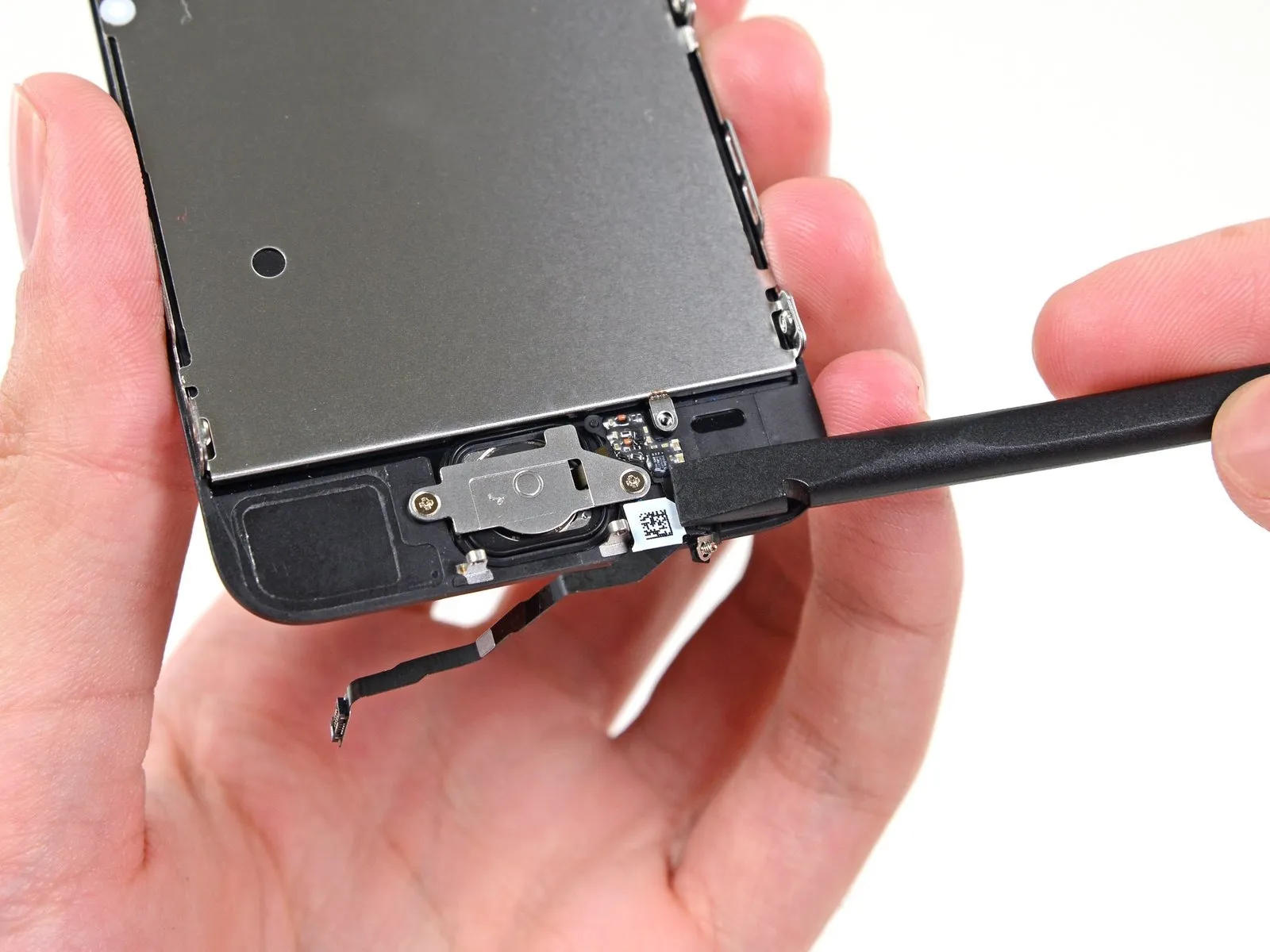
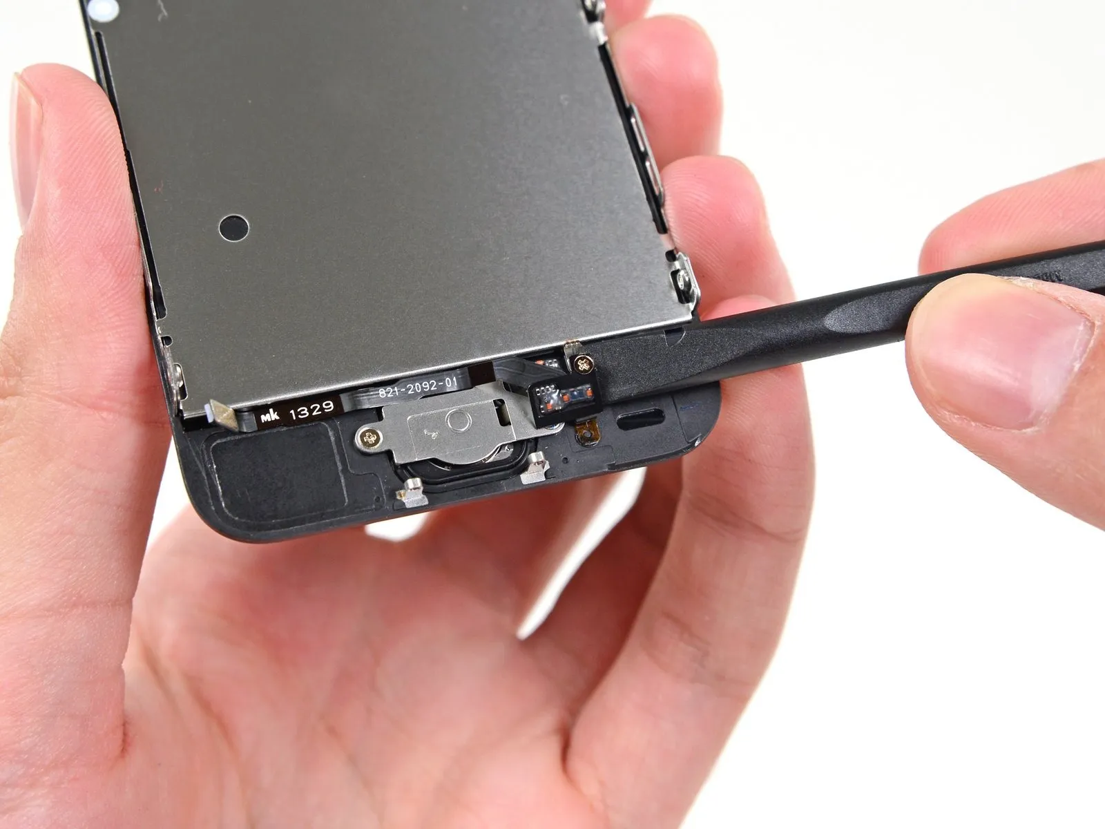
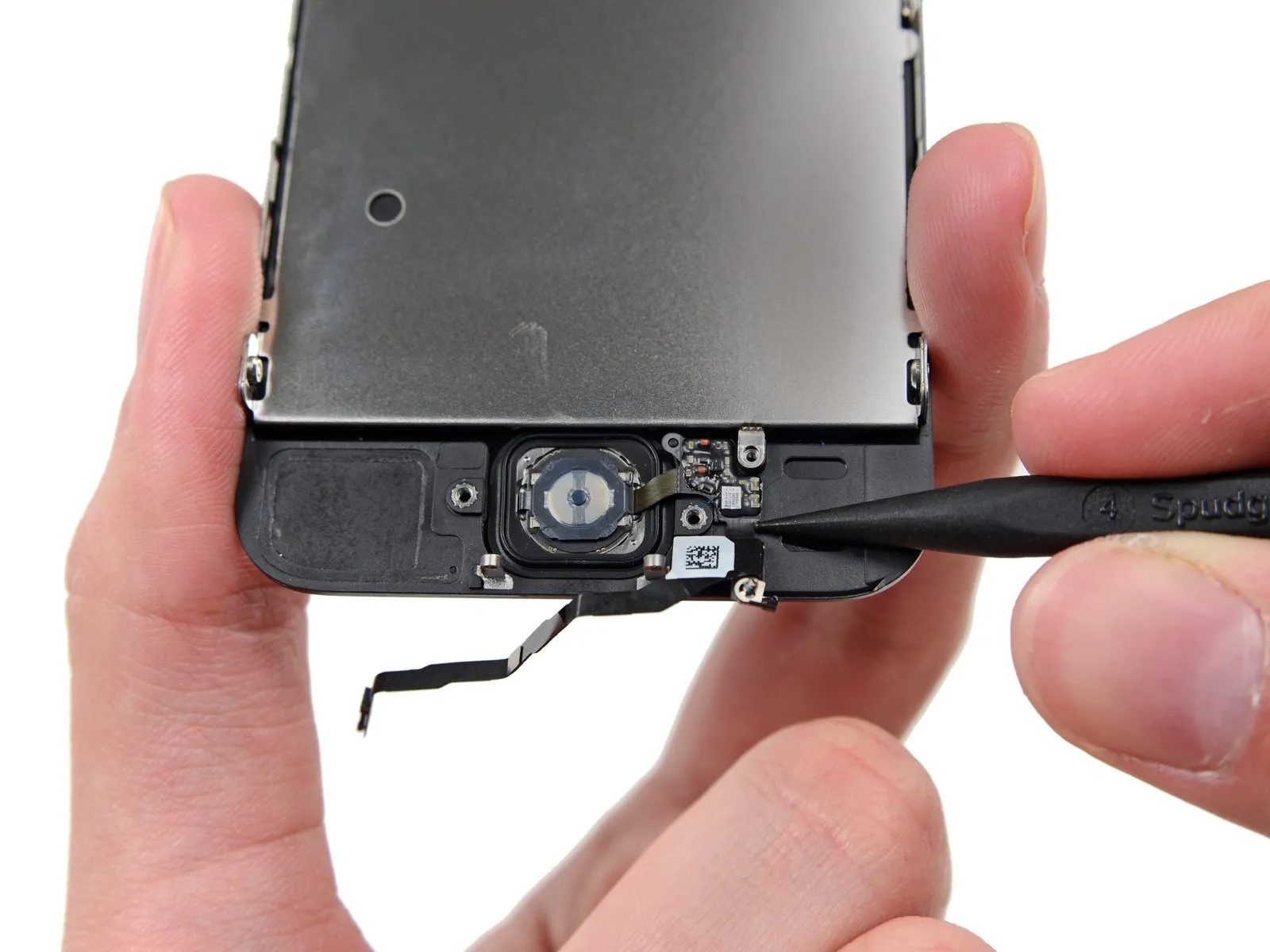
Step 12 | Disconnecting the home button cable connector


Carefully lift the home button cable connector from its socket using the pointed end of a spudger.
Avoid lifting the socket assembly; instead, carefully disconnect the cable connector from the socket. Damage can occur if you inadvertently lift the socket, as it's secured to the chassis with adhesive.
Avoid lifting the socket assembly; instead, carefully disconnect the cable connector from the socket. Damage can occur if you inadvertently lift the socket, as it's secured to the chassis with adhesive.
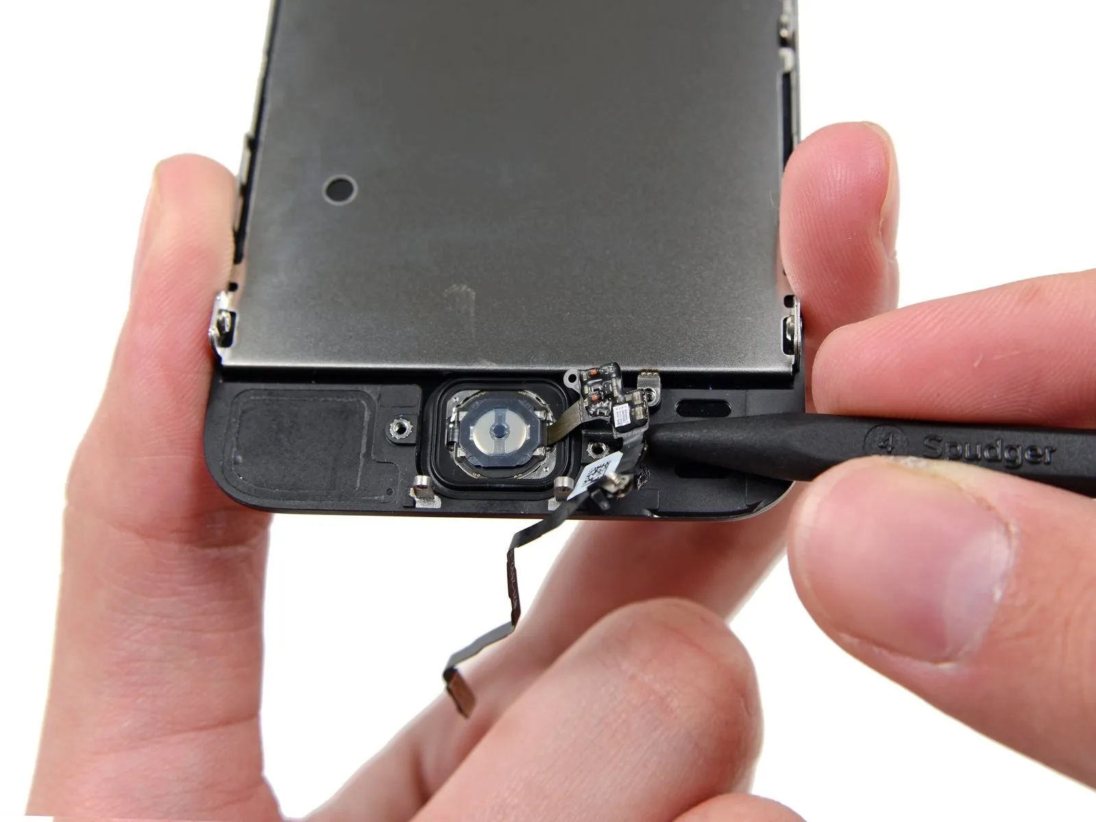
Step 13 | Opening up the phone


Carefully detach the connector, then pivot the home button portion of the assembly outward, utilizing the phone's upper edge as a fulcrum.
Carefully position the display at a 90-degree angle, then secure it in a supported position to prevent movement during the repair process.
To avoid stressing the display's wiring during the repair process, secure it with a rubber band.
As a temporary measure, an unused, sealed can of soda can substitute for the display during the repair process.
Step 14

Using a Phillips #000 screwdriver, detach the metal battery connector bracket from the logic board by unscrewing the two 1.6 mm screws that hold it in place.
Step 15

Using a precision screwdriver, detach the bracket securing the battery connector.
Step 16


Carefully lift the battery connector away from its corresponding socket on the logic board, employing the flat edge of a spudger to avoid damage.
Exercise extreme caution during the lifting process, ensuring force is applied solely to the battery connector; applying pressure to the logic board socket or the board's surface risks socket destruction or damage to adjacent components.
Exercise extreme caution during the lifting process, ensuring force is applied solely to the battery connector; applying pressure to the logic board socket or the board's surface risks socket destruction or damage to adjacent components.
Step 17

Detach the cable bracket from the logic board by unscrewing the listed fasteners.
Carefully manage all screws during this stage to ensure correct reassembly; improper placement, such as using a 1.3 mm or 1.7 mm screw in the bottom right hole, will severely damage the logic board and prevent the device from powering on.
Avoid applying excessive force when fastening screws; overtightening can damage components. Should a screw resist proper engagement during installation, verify its size against the specification to ensure it is correct.
- A Phillips screwdriver, size #000, is needed to remove a 1.7-millimeter screw.
- A Phillips head screw, size #000 and measuring 1.2 millimeters.
- A Phillips screwdriver, size #000, is needed to remove a 1.3-millimeter screw.
- An additional screw, measuring 1.7 mm in width and utilizing a Phillips #000 head, is required.
Carefully manage all screws during this stage to ensure correct reassembly; improper placement, such as using a 1.3 mm or 1.7 mm screw in the bottom right hole, will severely damage the logic board and prevent the device from powering on.
Avoid applying excessive force when fastening screws; overtightening can damage components. Should a screw resist proper engagement during installation, verify its size against the specification to ensure it is correct.
Step 18

Detach the bracket securing the front panel assembly cable to the logic board.
Step 19


Carefully detach the front camera and sensor cable assembly from its connector using a spudger or similar non-conductive tool.
Step 20


Prior to either detaching or reattaching the cable in this procedure, ensure the battery is disconnected.
Carefully detach the LCD cable connector.
Should the LCD cable become detached from its connector during reassembly, a blank screen or the appearance of white lines may occur upon powering on the device. To resolve this, firmly reseat the cable and restart the phone; for a complete restart, disconnect and reconnect the battery.
Step 21


Carefully separate the digitizer cable connector to release its connection.
Step 22

Detach the front panel assembly from the rear case.
Step 23 | Home Button Assembly
Using a Phillips #000 screwdriver, release the single screw that holds the home button cable in place; this screw is captive and cannot be fully removed.
To reinstall the captive screw, position the spring contact so it faces toward the LCD, as it provides backing against the home button cable.
To ensure proper functionality, relocate the existing screw and spring contact to the new cable if they are not already present on the replacement part.
To reinstall the captive screw, position the spring contact so it faces toward the LCD, as it provides backing against the home button cable.
To ensure proper functionality, relocate the existing screw and spring contact to the new cable if they are not already present on the replacement part.
Step 24
To prevent interference, carefully maneuver the home button cable so it lies flat and clear of the home button bracket's intended position.
Step 25
Using a Phillips #000 screwdriver, detach the home button bracket by unscrewing the pair of 1.4 mm screws securing it.
Step 26
Detach the bracket securing the home button to the display assembly.
Step 27
Carefully insert the pointed end of a spudger to create a gap beneath the home button cable assembly.
A light adhesive secures the home button cable.
Using a spudger, carefully disengage the home button cable from the front panel assembly by sliding the tool between the cable and the assembly.
The front panel assembly retains the home button; therefore, avoid detaching it at this stage.
A light adhesive secures the home button cable.
Using a spudger, carefully disengage the home button cable from the front panel assembly by sliding the tool between the cable and the assembly.
The front panel assembly retains the home button; therefore, avoid detaching it at this stage.
Step 28
Carefully peel away any protective tape covering the home button located on the exterior of the damaged front panel assembly, if present.
Using careful, even pressure, lift the upper-left portion of the home button, separating it from the display assembly.
Instead of fully depressing the home button, release it just enough to expose a corner, allowing you to use a spudger to gently separate it.
Due to its delicate nature, the membrane is prone to damage; should you encounter resistance that suggests tearing, gently warm the area and reattempt the process.
Step 29
Using a spudger, carefully detach the remaining adhesive securing the home button to the display surface.
Step 30
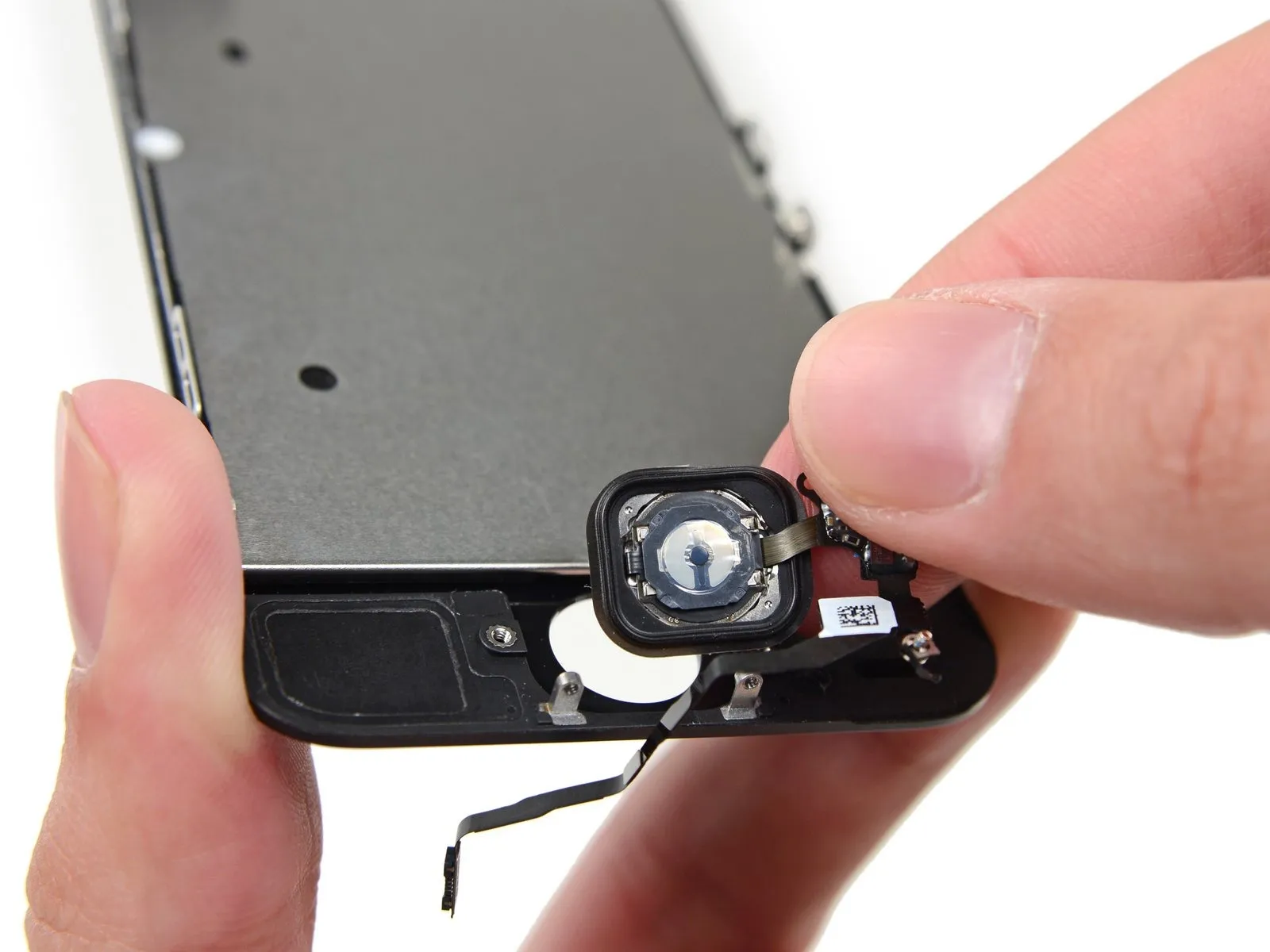
Carefully detach the home button assembly from the front panel.
Step 31 | Home Button


Using a 5/32-inch hex key, carefully tighten the four M4x8mm screws securing the fan assembly to the heatsink, ensuring a torque of 4.5 in-lbs to prevent damage.
Carefully move the gasket from the original home button to the new assembly, ensuring proper alignment.
Carefully detach the gasket from the home button by using tweezers.
Because the gasket's thickness is minimal, discontinue the peeling process immediately if any tearing occurs and apply heat to the area before continuing.
Step 32

Using a 5/32-inch hex key, carefully tighten the four M4x8 pan head screws securing the fan assembly to the heatsink, ensuring a torque of 4 in-lbs to prevent damage.
Carefully remove the gasket from the ribbon cable by sliding it away.
Care must be taken when detaching the gasket located above the home button, as its delicate nature makes it susceptible to damage like tearing or deformation.
Carefully remove the gasket from the ribbon cable by sliding it away.
Care must be taken when detaching the gasket located above the home button, as its delicate nature makes it susceptible to damage like tearing or deformation.