iPhone 5s Front Facing Camera and Sensor Cable Replacement
This guide details the procedure for substituting the iPhone 5s sensor cable assembly, which incorporates the front camera, microphone, ambient light and proximity sensors, and the earpiece speaker contact pad.
- This document serves as a resource for substituting the listed components as well.
Step 1 | Removing the Pentalobe screws

Begin by disconnecting the power supply, ensuring it is unplugged from the electrical outlet, then carefully remove the retaining screw—measuring 1/2 inch in diameter—securing the fan motor using a Phillips head screwdriver, and gently detach the fan motor assembly.To prevent a potential fire or explosion hazard during repair, ensure the iPhone's lithium-ion battery is depleted to less than 25% capacity prior to beginning work; a fully charged battery poses a significant risk of ignition if damaged.
To prevent electrical shock or damage, ensure the iPhone is completely de-energized prior to starting the repair process.
Using a Pentalobe screwdriver, detach the two screws, each measuring 3.9 mm, located on both sides of the Lightning connector.
To prevent electrical shock or damage, ensure the iPhone is completely de-energized prior to starting the repair process.
Using a Pentalobe screwdriver, detach the two screws, each measuring 3.9 mm, located on both sides of the Lightning connector.
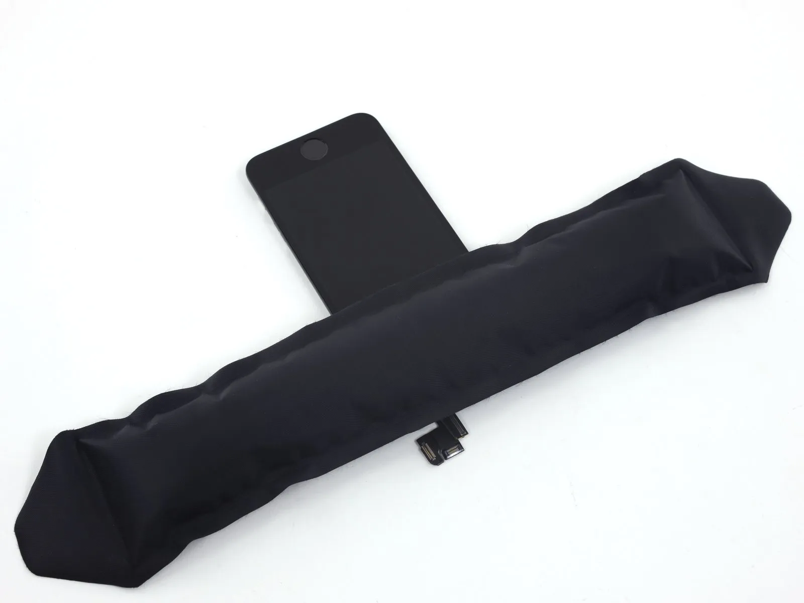
Step 2 | Taping the display glass


Using a 5/32-inch hex key, carefully tighten the retaining screw on the motor assembly to a torque of 3.5 Nm, ensuring the motor shaft aligns correctly and observing the warning regarding potential pinch points.To avoid injury and contain shattered fragments while you work, secure any cracked display glass with tape.
Apply strips of transparent packing tape across the iPhone screen, ensuring complete coverage by layering them until the entire display surface is protected.
To prevent glass fragments from scattering and maintain stability during the display separation process, ensure this step is performed carefully.
To safeguard your eyes from potential glass fragments released during the repair process, always use safety glasses.
Step 3 | Display separation prevention


Using a 5/32-inch hex key, carefully loosen the four screws securing the fan assembly to the motor housing; ensure the screws are not fully removed, but rather remain slightly engaged to prevent component loss, and observe the warning regarding potential propeller damage during this process.Carefully lift the display assembly—consisting of a glass screen, a plastic bezel, and integrated metal clips—from within the phone's chassis during the subsequent procedures.
Ensure complete removal of the display assembly, irrespective of the chosen tool.
When the glass and plastic layers detach, referencing the initial image for visual guidance, use a plastic opening tool to insert it into the gap between the plastic frame and the phone's metal chassis, carefully levering the metal clips away from the case.
To facilitate reassembly when the display bezel is detached, a narrow adhesive strip can be positioned between the plastic bezel and the glass panel, ensuring the phone remains securely closed.
Step 4 | Anti-Clamp instructions


Using a 5/32-inch hex key, carefully tighten the four mounting screws securing the fan assembly to the motor housing, ensuring each is snug but not over-torqued to prevent damage.To simplify the subsequent opening process, the following two steps utilize the Anti-Clamp tool, a custom design; if you do not have this tool, proceed two steps further to find an alternative approach.
Refer to the accompanying guide for detailed procedures regarding the Anti-Clamp's operation.
To release the Anti-Clamp's arms, move the blue handle in a rearward direction.
Position the arms so they extend across the iPhone's left or right side.
Secure two suction cups, one to the front and one to the rear surface of the iPhone, placing them close to the lower edge, directly above the home button.
Apply vacuum to the targeted region by pressing the cups firmly against each other.
To improve the Anti-Clamp's grip on a slick iPhone exterior, apply the provided adhesive pad to the device's surface.
Step 5


Using a 5/32-inch hex key, carefully tighten the three retaining screws securing the fan assembly to the motor housing, ensuring each is snug but not over-tightened to avoid damaging the plastic threads; observe the torque limit of 3 in-lbs per screw.Advance the blue handle to engage the locking mechanism on the arms.
Rotate the handle fully, completing a 360-degree turn, observing for the initial expansion of the cups.
Maintain parallel positioning of the suction cups; should misalignment occur, gently reduce the suction and reposition the arms.
Once sufficient space is created by the Anti-Clamp, slide a prying tool beneath the display.
To ensure adequate separation, reposition the handle by 90 degrees.
Apply adjustments incrementally, limiting each rotation to a maximum of 90 degrees, and pause for several seconds after each adjustment to allow the Anti-Clamp mechanism and dwell time to facilitate proper seating.
Step 6 | Manual Opening Procedure

Lacking an Anti-Clamp tool, secure the front panel with a single suction cup for lifting.
Position a suction cup directly on the display surface, situated slightly higher than the home button's location.
Ensure the cup's entire surface makes contact with the screen to guarantee a secure seal.
Position a suction cup directly on the display surface, situated slightly higher than the home button's location.
Ensure the cup's entire surface makes contact with the screen to guarantee a secure seal.
Step 7 | Start lifting the front panel assembly

Detach the front panel by releasing the retaining clips, then carefully separate the phone's housing just enough to access and disconnect the multiple ribbon cables—proceed with caution to prevent component damage.
Securely affix the suction cup to the front panel assembly, positioning it close to the home button.
Using one hand to secure the iPhone, lift the suction cup vertically to gently create a small gap between the front panel and the rear case, beginning at the home button area.
Using a plastic opening tool, lift the rear case's perimeter edges away from the front panel assembly, applying upward force with a suction cup.
Exercise caution and use steady, even pressure when installing the front panel assembly, as its fit is considerably more snug compared to typical device construction.
Step 8


Disconnecting the front panel assembly from the rear case should be avoided; multiple fragile ribbon cables secure the components together.
To detach the suction cup, depress the plastic projection to break the airtight seal.
Carefully detach the screen from the device using the suction cup.
To detach the suction cup, depress the plastic projection to break the airtight seal.
Carefully detach the screen from the device using the suction cup.
Step 9 | Removing the Touch ID cable bracket


Carefully separate the phone's casing to expose the metallic support securing the home button cable.
To prevent damage to the home button cable and its connector, avoid excessive separation of the phone's housing; maintain slack in the cable, as overextension can cause harm.
The Touch ID feature is exclusive to the factory-installed home button assembly; replacement with a non-original part will result in a standard home button only, lacking Touch ID capabilities, and any damage to the connecting cable will produce the same outcome.
Carefully leverage the bracket loose using a spudger tip, then grasp and detach it with tweezers.
For reassembly procedures, proceed with the subsequent two instructions; otherwise, bypass them and move directly to Step 12.
Step 10


To complete reassembly, secure the Touch ID cable bracket by positioning its upper edge between the battery and the Touch ID cable connector, ensuring it sits ahead of the metal tab, then fasten the bracket’s lower edge by engaging it with the connector.
Align the bracket's upper edge with the Touch ID cable connector and move it horizontally to the right.
Position the bracket so it covers the connector, ensuring the "leg" side creates a small incline and the opposite edge sits between the cable connector and the battery's adjacent metal tab. Using a spudger, press gently downward on the bracket’s surface to secure both the rear and front clasps.
Step 11


Carefully position the Touch ID cable connector, then secure the front section of the bracket by pressing it firmly into place with the flat edge of a spudger.
To ensure the bracket sits level against the surface, reposition it by sliding it back over the cable connector if it doesn't seat properly.
To ensure the bracket sits level against the surface, reposition it by sliding it back over the cable connector if it doesn't seat properly.
Step 12 | Disconnecting the home button cable connector


Carefully lift the home button cable connector from its socket using the pointed end of a spudger.
Carefully disconnect the cable connector from its receptacle, avoiding upward force on the receptacle itself; the receptacle is affixed to a separate, adhesive-backed cable that can detach if excessive leverage is applied.
Carefully disconnect the cable connector from its receptacle, avoiding upward force on the receptacle itself; the receptacle is affixed to a separate, adhesive-backed cable that can detach if excessive leverage is applied.
Step 13 | Opening up the phone


Carefully detach the connector, then pivot the home button portion of the assembly outward, utilizing the phone's upper edge as a fulcrum.
Carefully position the display at a roughly 90-degree angle, then secure it in a supported position using a prop to prevent movement during the repair process.
To avoid stressing the display's wiring during the repair process, secure it with a rubber band.
As a temporary substitute, an unused, sealed can of soda can be employed to secure the display in place.
Step 14

Using a Phillips #000 screwdriver, detach the metal battery connector bracket from the logic board by unscrewing the two 1.6 mm screws that hold it in place.
Step 15

Detach the bracket securing the battery connector using a tri-point screwdriver, ensuring no damage occurs to the connector or surrounding components.
Step 16


Carefully lift the battery connector away from its corresponding socket on the logic board, employing the flat edge of a spudger to avoid damage.
Exercise extreme caution when releasing the battery connector; lifting force should be applied solely to the connector, avoiding any pressure on the logic board socket or the board's surface, as this could result in socket damage or harm to adjacent components.
Exercise extreme caution when releasing the battery connector; lifting force should be applied solely to the connector, avoiding any pressure on the logic board socket or the board's surface, as this could result in socket damage or harm to adjacent components.
Step 17

Detach the cable bracket, which holds the front panel assembly wiring, from the logic board by unscrewing the screws listed below.
Carefully manage all screws during this procedure to ensure correct reassembly; incorrect placement, such as using a 1.3 mm or 1.7 mm screw in the bottom right hole, will severely damage the logic board and prevent the device from powering on.
Avoid applying excessive force when tightening screws; if resistance is encountered during installation, verify that the correct screw size is being used.
- A Phillips screwdriver, size #000, is needed to remove a 1.7-millimeter screw.
- A Phillips head screw, size #000 and measuring 1.2 millimeters.
- A Phillips screwdriver, size #000, is needed to remove a 1.3-millimeter screw.
- An additional screw, measuring 1.7 mm in width and utilizing a Phillips #000 head, is required.
Carefully manage all screws during this procedure to ensure correct reassembly; incorrect placement, such as using a 1.3 mm or 1.7 mm screw in the bottom right hole, will severely damage the logic board and prevent the device from powering on.
Avoid applying excessive force when tightening screws; if resistance is encountered during installation, verify that the correct screw size is being used.
Step 18

Detach the bracket securing the front panel assembly cable to the logic board.
Step 19


Carefully detach the front camera and sensor cable assembly from its connector using a spudger or similar non-conductive tool.
Step 20


Prior to either detaching or reattaching the cable in this procedure, ensure the battery is disconnected.
Carefully detach the LCD cable connector.
Should the LCD cable become detached from its connector during reassembly, a blank screen or the appearance of white lines may occur upon powering on the device. To resolve this, re-establish the cable's connection and restart the phone; for a complete restart, disconnect and reconnect the battery.
Step 21


Carefully separate the digitizer cable connector to release its connection.
Step 22

Detach the front panel assembly by disengaging it from the rear case.
Step 23 | Earpiece Speaker
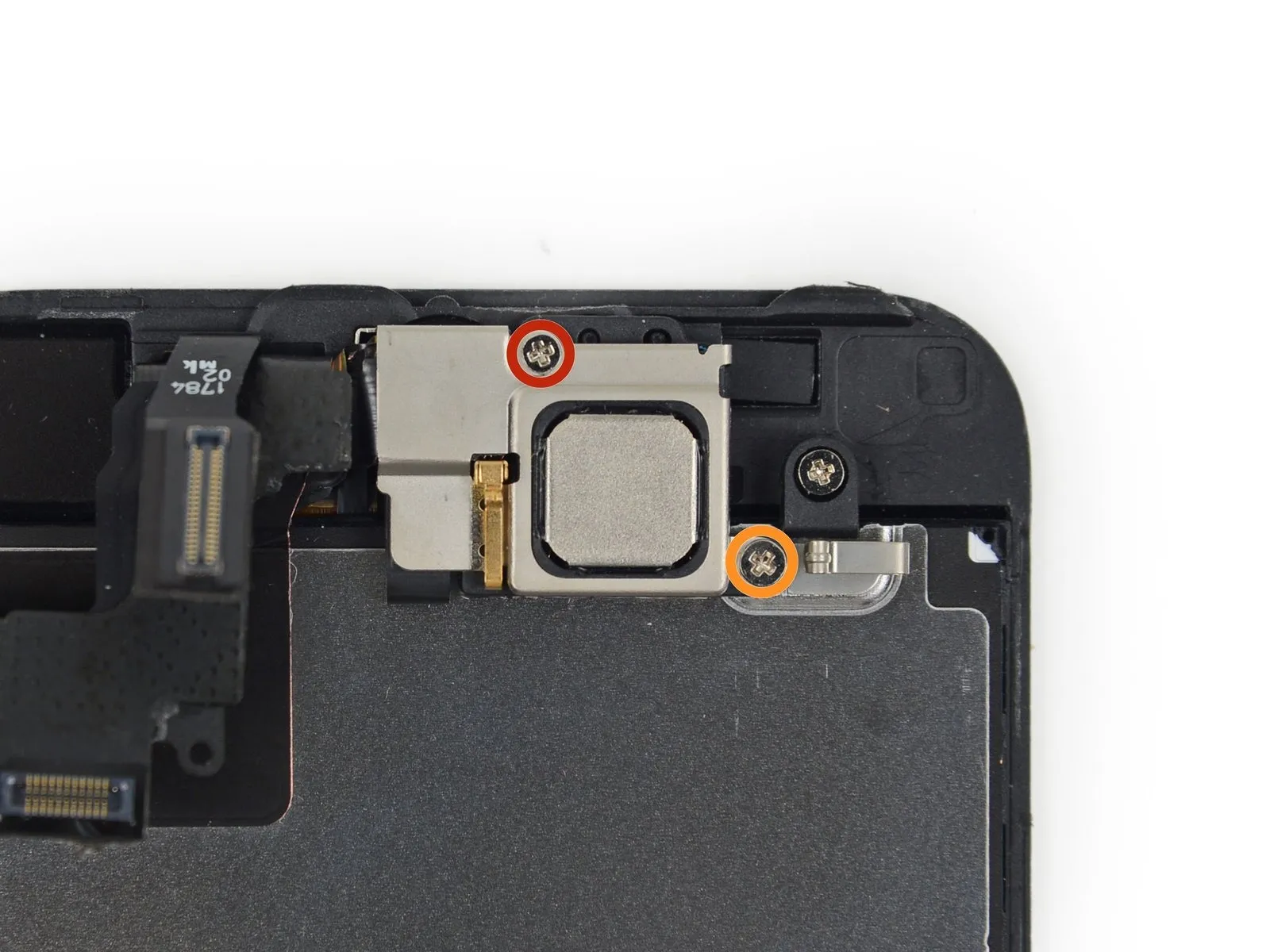
Detach the upper component bracket by unscrewing the two fasteners that hold it in place.
Use a Phillips head screwdriver, size #000, with a tip measuring 4.0 millimeters.
Use a Phillips head screwdriver, size #000, with a 2.3-millimeter shaft.
Using the correct screw size for each designated hole is critical; improper screw selection can result in significant LCD damage during reassembly.
Step 24
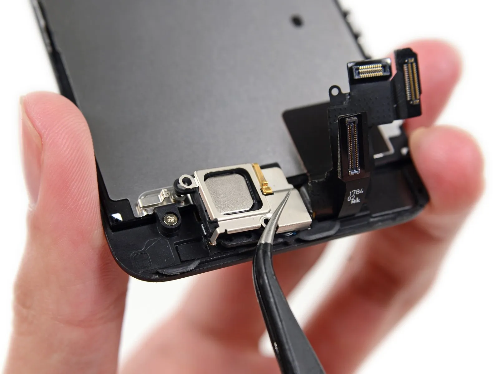
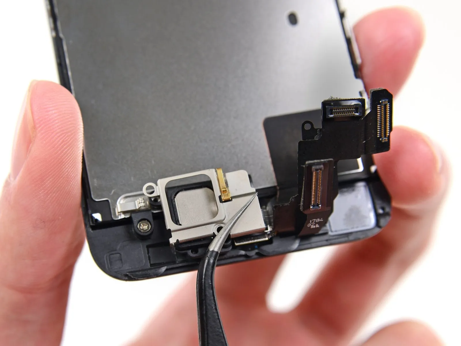
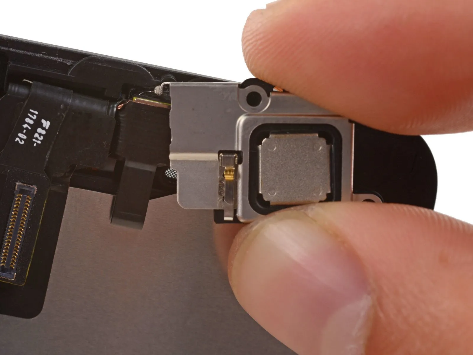
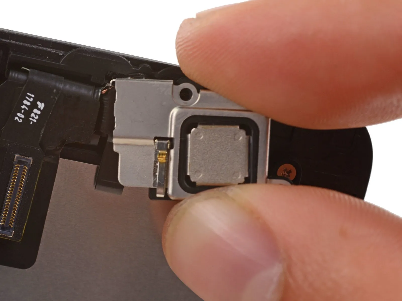
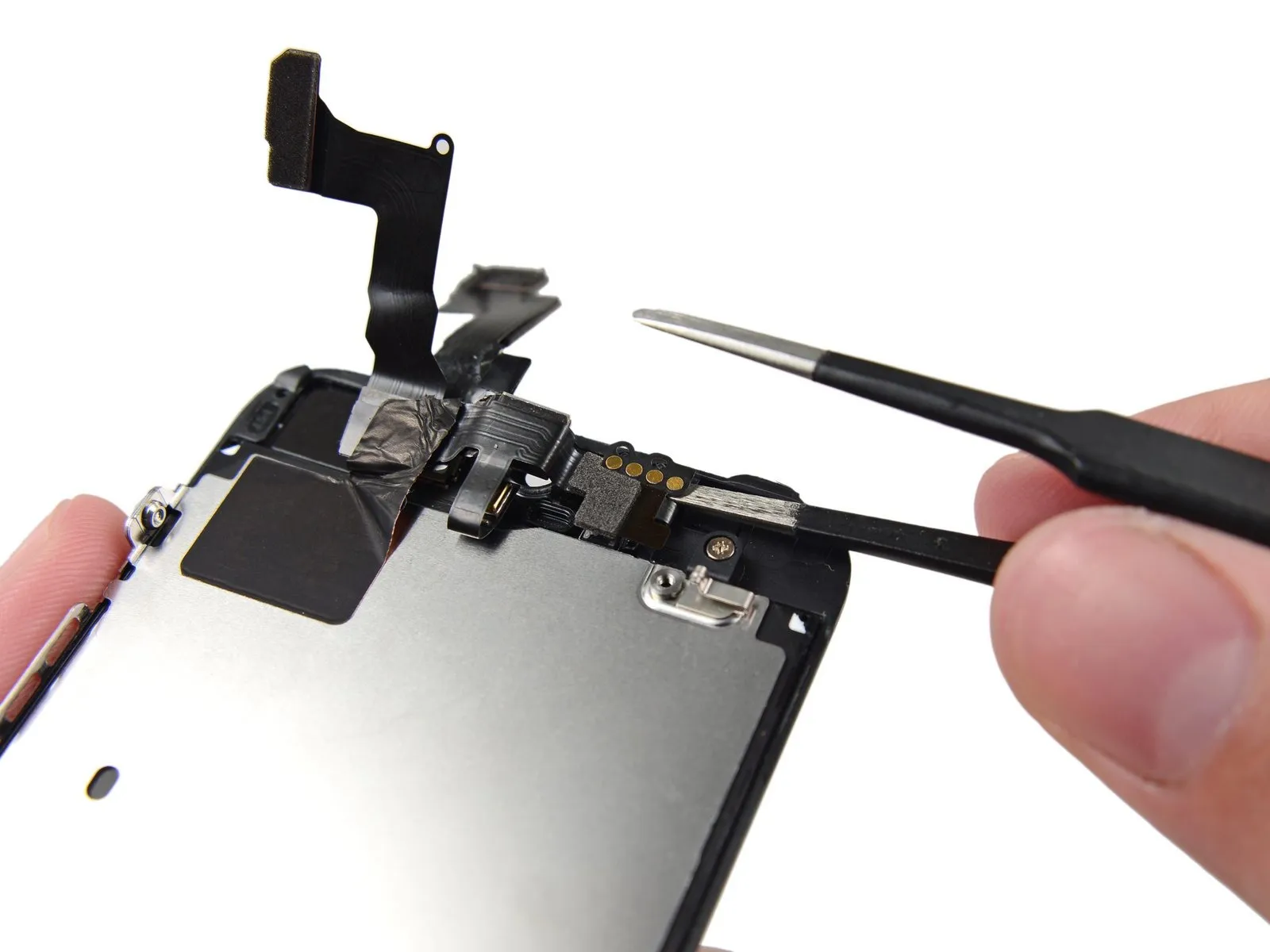
Position the device so that the physical home button is located at the uppermost edge and the earpiece speaker faces downward, mirroring the illustrated orientation.
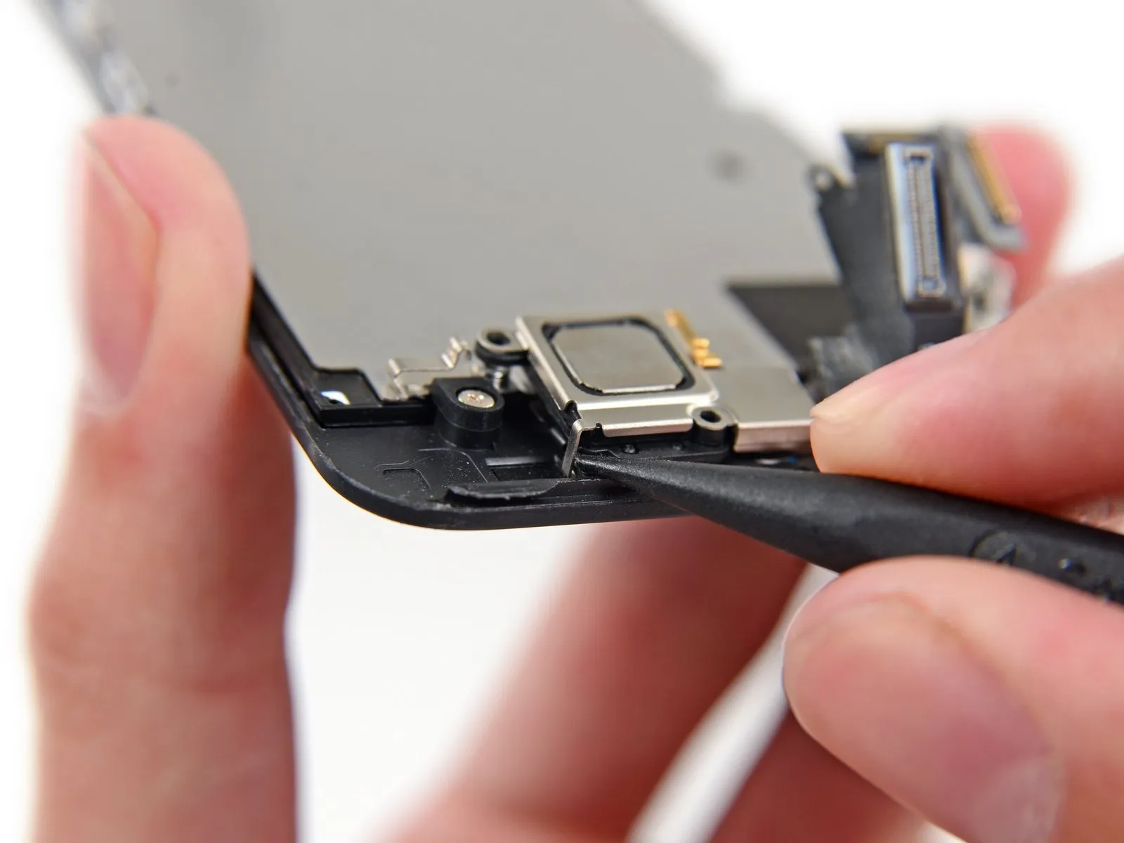
Carefully move the clip, positioned close to the lower-left edge of the earpiece speaker bracket, away from its seating within the front panel assembly.
Applying too much pressure when separating components risks damaging the earpiece speaker bracket due to its delicate and flexible nature.
Using tweezers, move the bracket laterally to the left until the clip releases.
Step 25
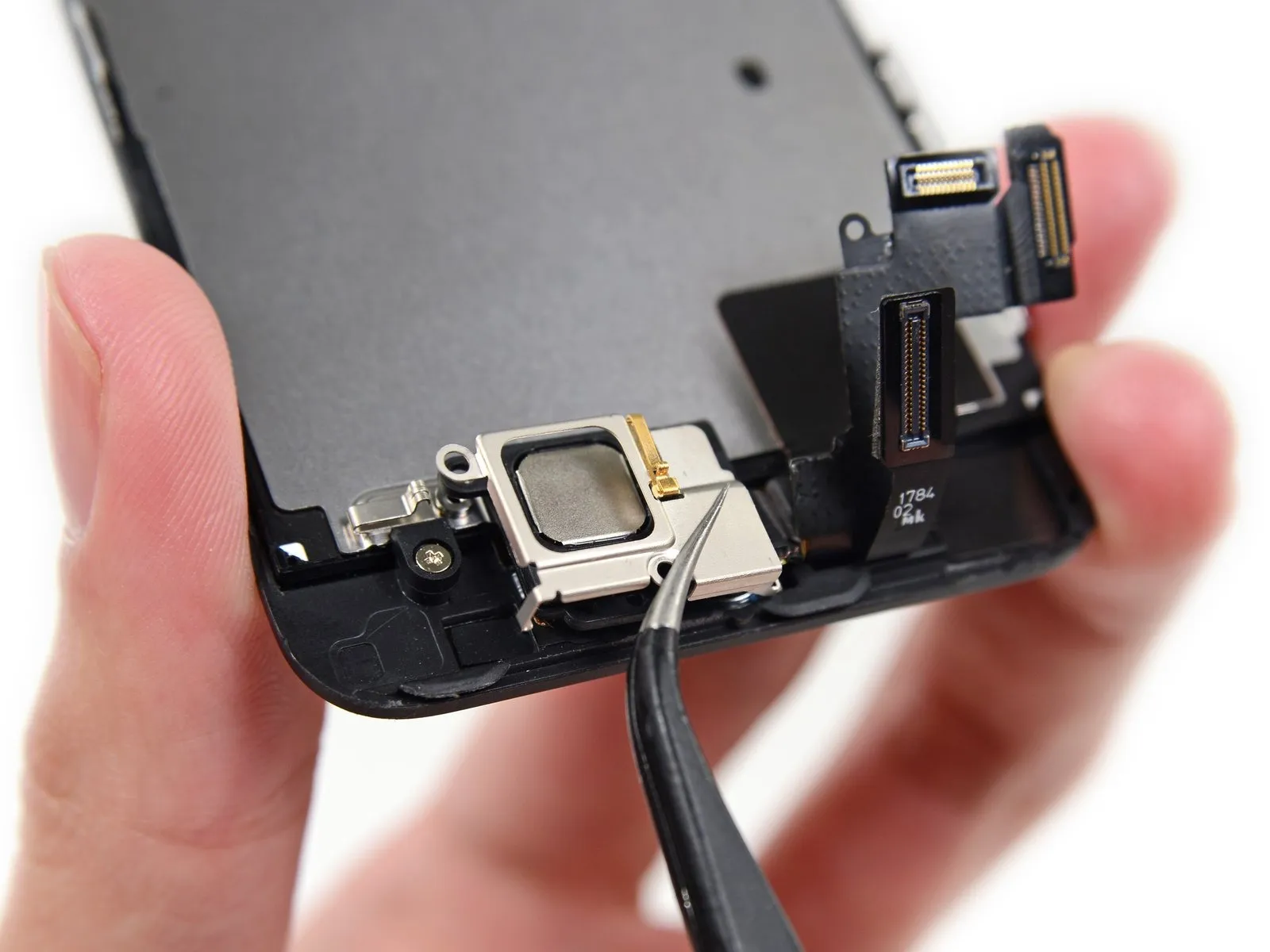
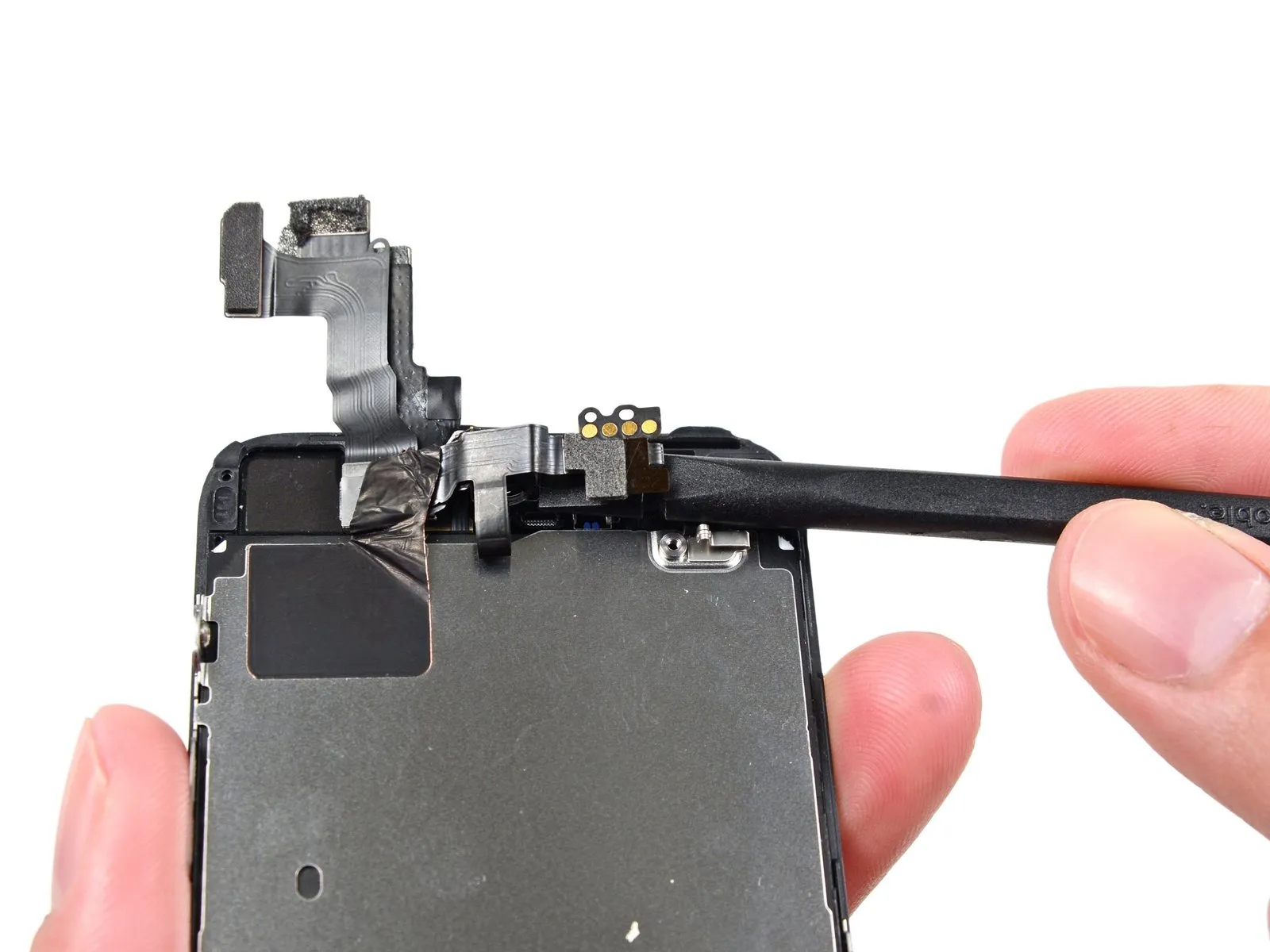
Detach the display's bracket.
Step 26
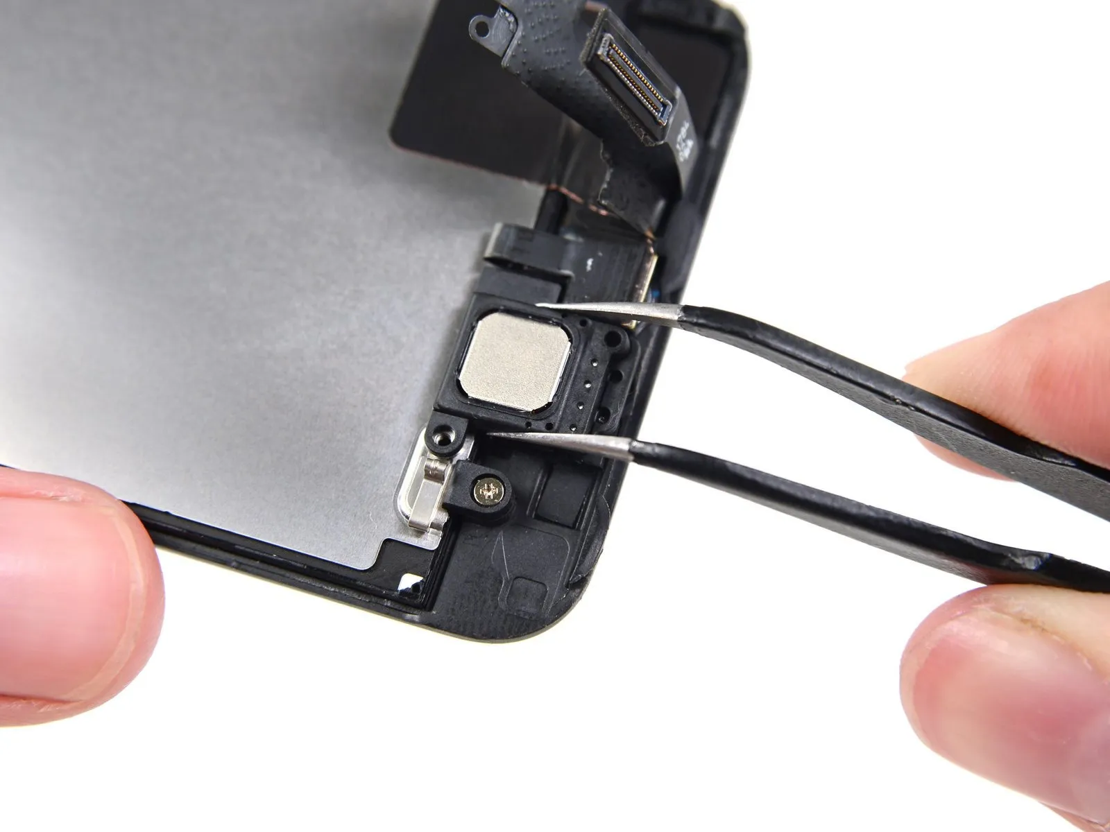
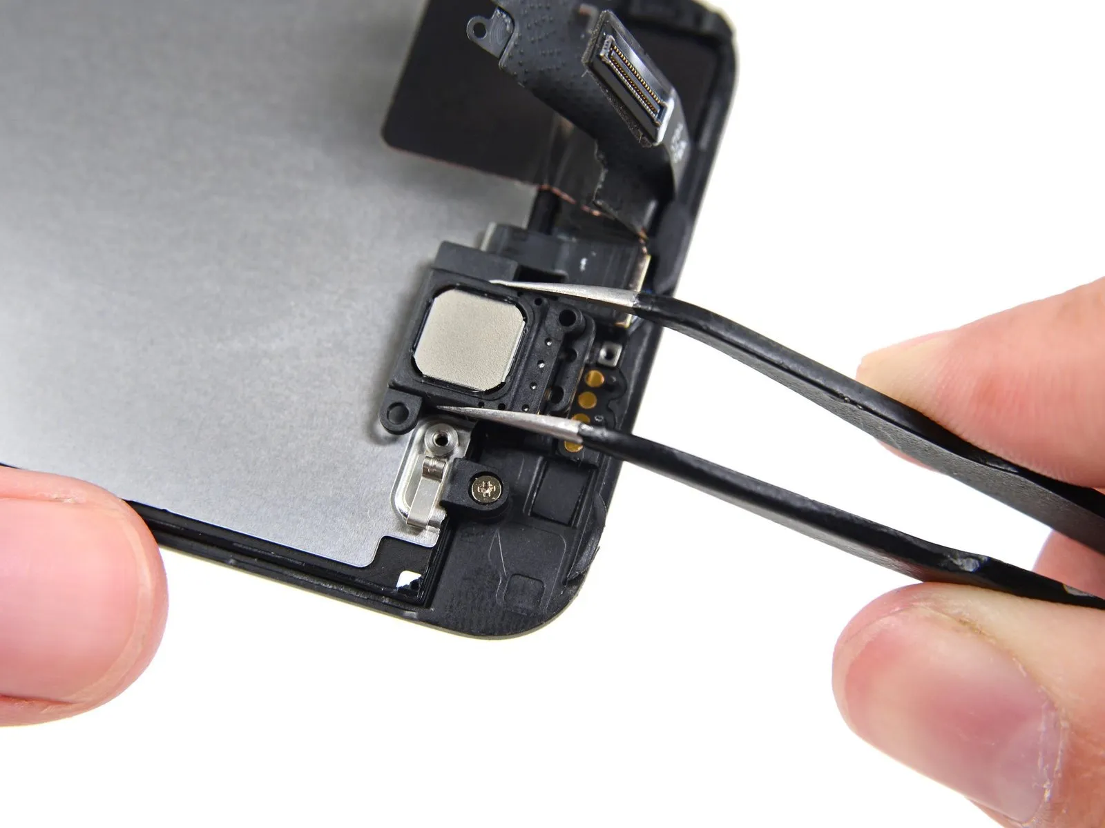
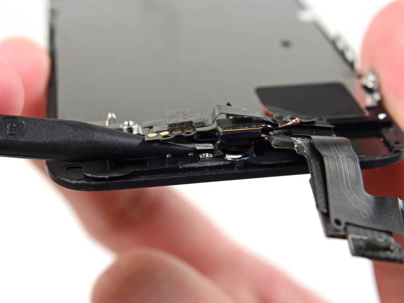
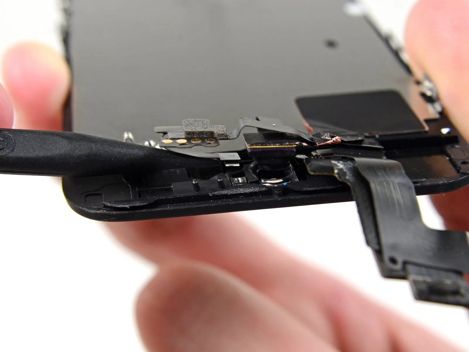
Using tweezers, carefully detach the earpiece speaker.
To avoid compromising electrical connections, exercise extreme caution and prevent any contact between your skin and the gold-plated connectors located on the front panel. Skin oils can impair contact quality.
To avoid compromising electrical connections, exercise extreme caution and prevent any contact between your skin and the gold-plated connectors located on the front panel. Skin oils can impair contact quality.
Step 27
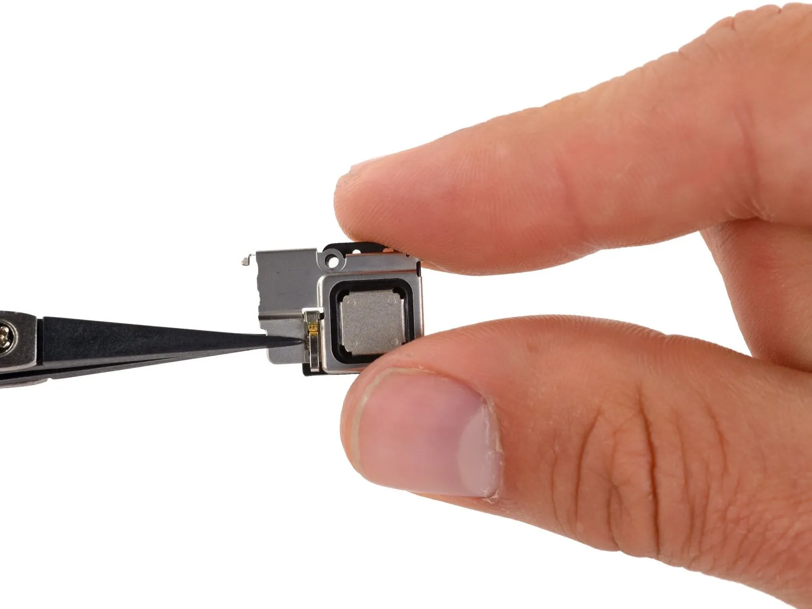
For earpiece speaker replacement, combine the speaker and its bracket during installation to simplify the process.
Align the speaker and its bracket, ensuring a secure and flush fit within the designated housing.
Align the bracket's left hook with the notch situated directly above the front-facing camera’s upper left corner, then insert it.
Position the bracket horizontally against the rear case, matching the screw holes. Secure the bracket by pressing it firmly, verifying that the right-side hook engages with the display.
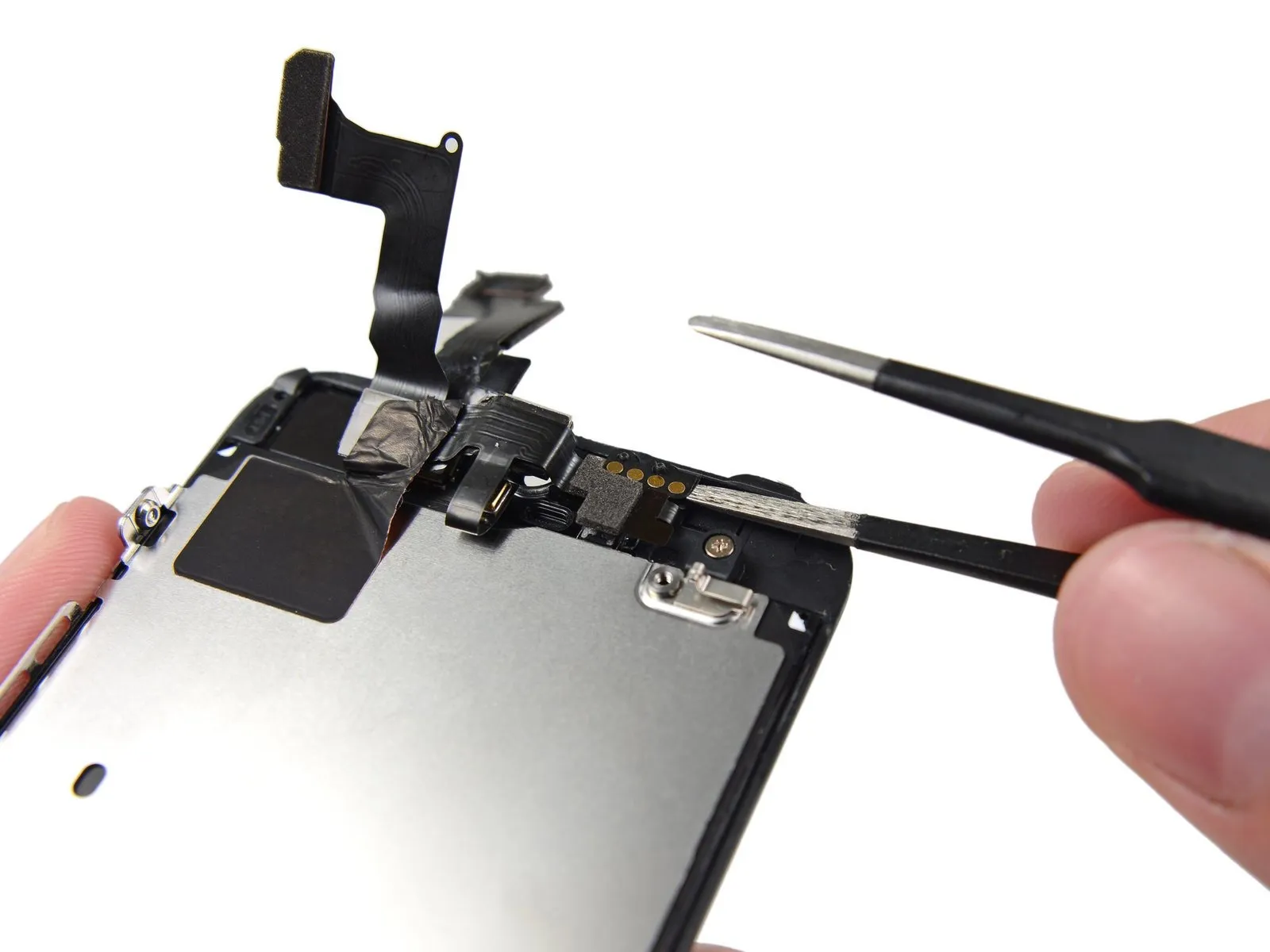
Step 28 | Front Facing Camera and Sensor Cable Assembly
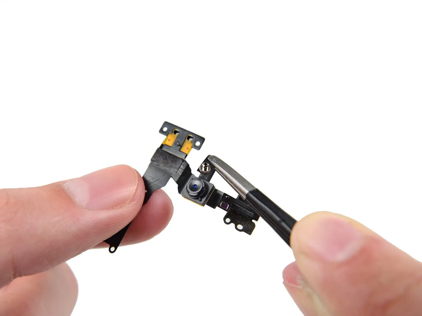
Detach the front panel assembly's front-facing camera and its associated sensor cable.
A light adhesive secures the front camera and its associated cable to the display assembly.
To ease adhesive separation, employ an iOpener, adhering to the established iOpener usage guidelines.
A light adhesive secures the front camera and its associated cable to the display assembly.
To ease adhesive separation, employ an iOpener, adhering to the established iOpener usage guidelines.
Step 29
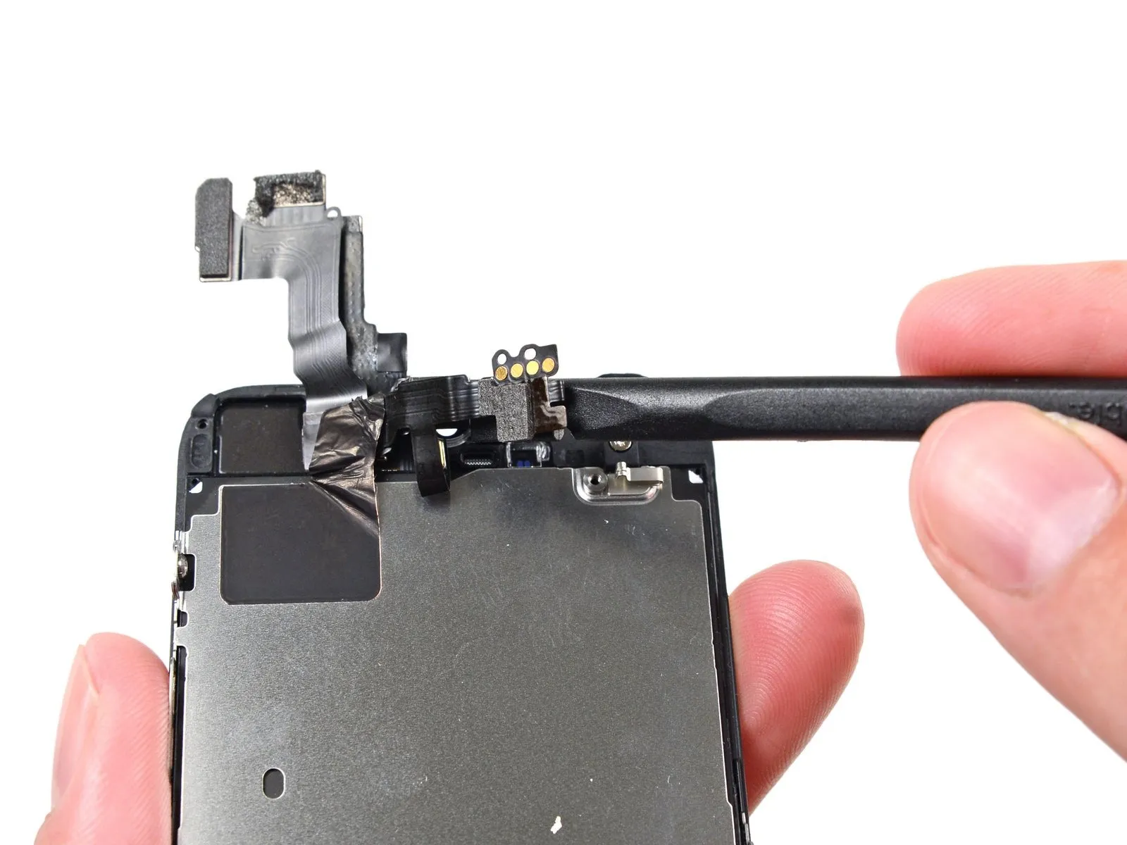
Carefully lift the earpiece speaker contact cable using tweezers or a metal spudger to release the adhesive securing it to the camera and sensor cable.
To avoid damaging sensitive components like sensors and microchips, limit your prying action specifically to the area beneath the earpiece speaker contacts.
To avoid damaging sensitive components like sensors and microchips, limit your prying action specifically to the area beneath the earpiece speaker contacts.
Step 30
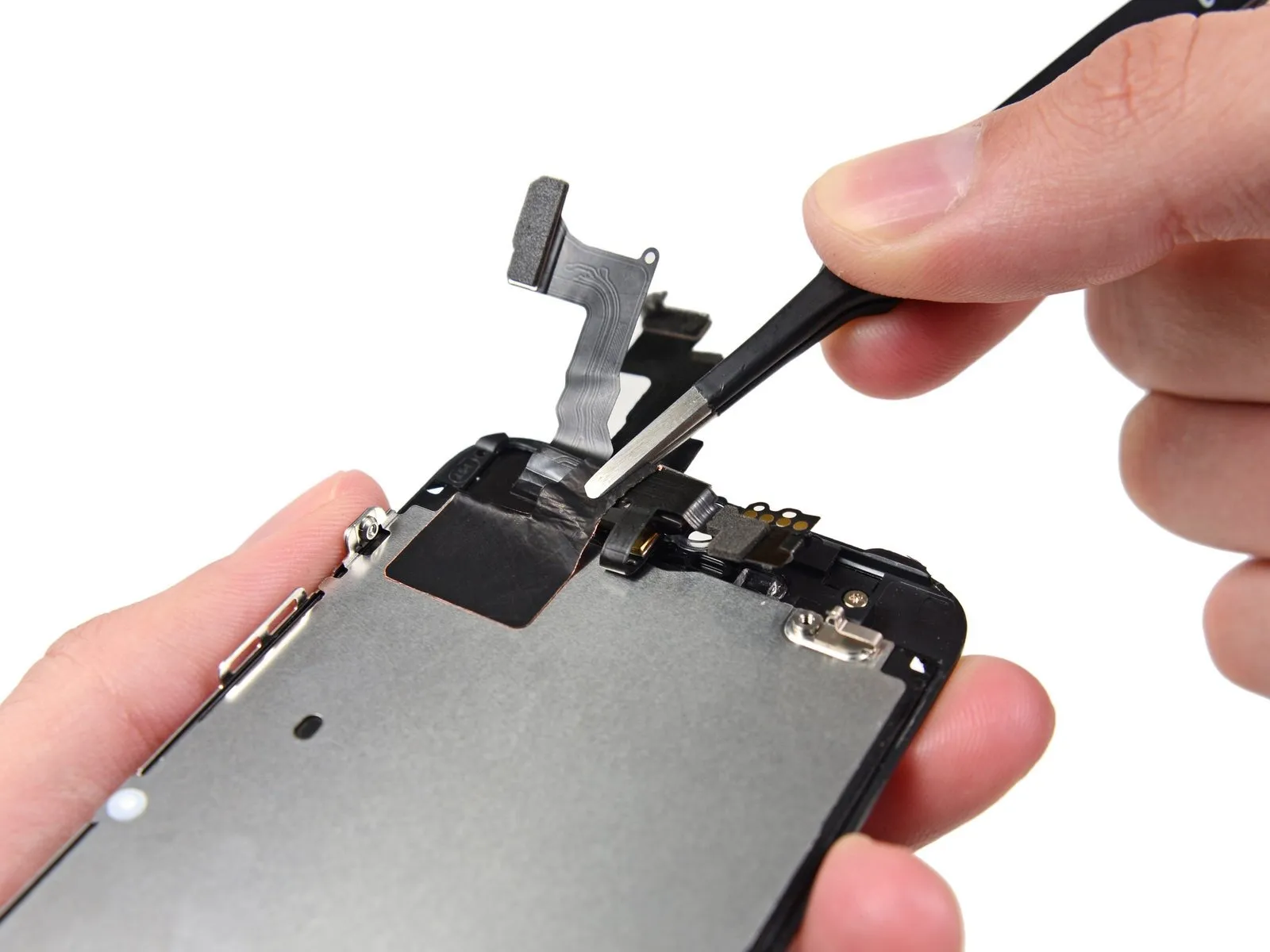
Carefully pry the ambient light sensor and proximity sensor from their molded slots within the display assembly using a spudger tip.
The proximity sensor's operation relies on a crucial, small bracket constructed from plastic and metal.
When substituting the proximity sensor, ensure the holder stays securely bonded to the display's rear surface; if it detaches with the removed sensor, carefully separate it from the discarded component and apply a small amount of adhesive to resecure it to the display.
Step 31
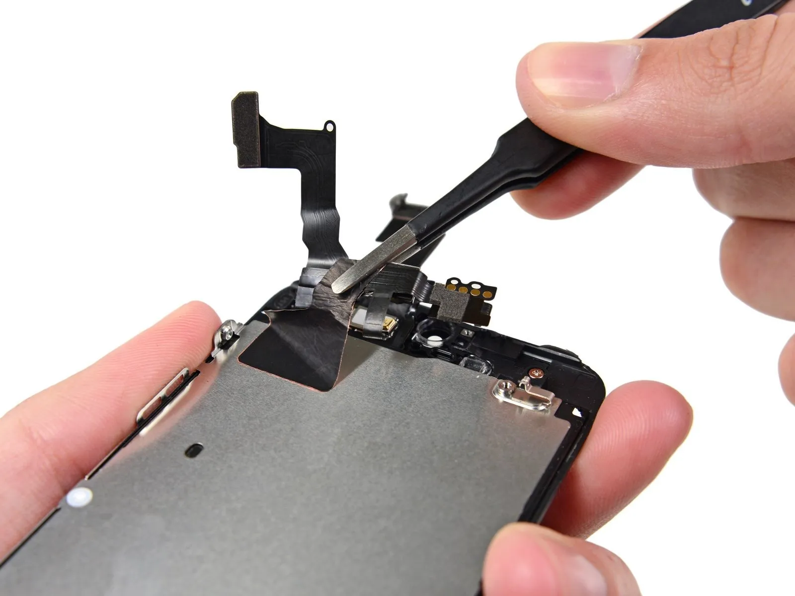
Carefully separate the front-facing camera cable from the display assembly by using the flat spudger tip to lift it gently.
Step 32
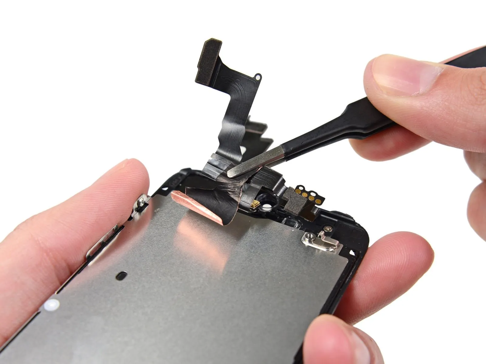
When reusing a shield plate with a replacement display, proceed to the next instruction without repeating this one.
Detach the cable assembly from the LCD shield plate by gently separating them, exercising caution during the process.
Avoid pulling on the digitizer cable during removal of the front-facing camera and sensor assembly.
Detach the cable assembly from the LCD shield plate by gently separating them, exercising caution during the process.
Avoid pulling on the digitizer cable during removal of the front-facing camera and sensor assembly.
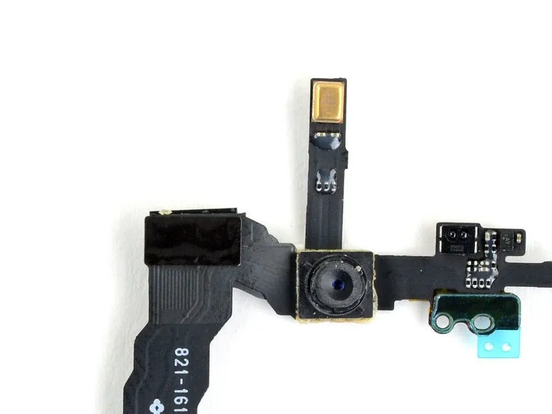
Step 33 | Front Facing Camera and Sensor Cable

Carefully detach all plastic protective films from the microphone located on the sensor cable assembly.
Step 34
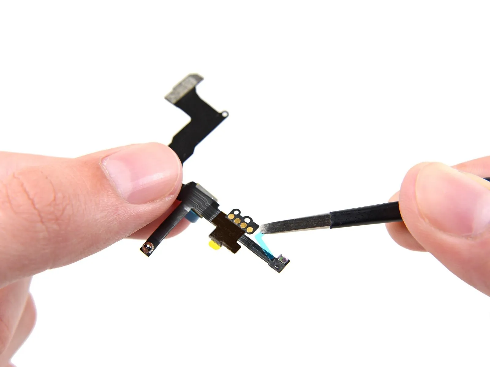


Carefully detach the protective adhesive strips from the light sensor, the connecting cable, and the front camera assembly.
Step 35

Verify the replacement cable assembly's dimensions and connector configuration against the original iPhone component to guarantee compatibility and correct positioning.
Carefully manipulate the cable's microphone section with tweezers, ensuring the gold-plated connector is nestled within the cable's interior while the silver component remains exposed on the exterior.
Carefully manipulate the cable's microphone section with tweezers, ensuring the gold-plated connector is nestled within the cable's interior while the silver component remains exposed on the exterior.
Step 36
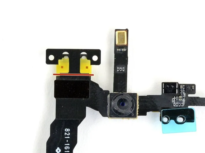
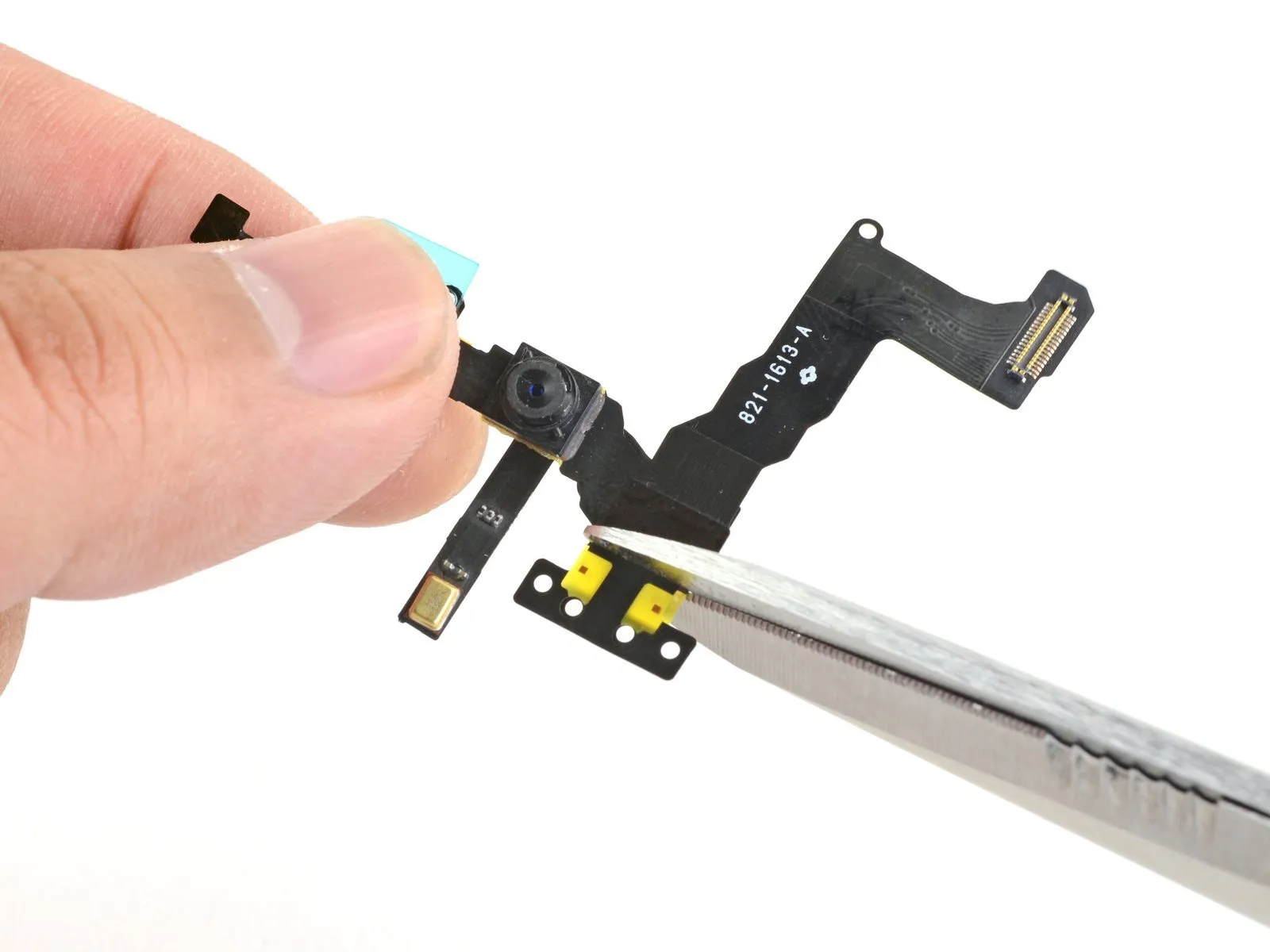
The new sensor cable may include a tab that is not required for installation; use caution to remove it with a cutting tool, as it is solely for factory testing purposes.
Employing scissors, sever the cable immediately beneath the two yellow plastic tabs.
Employing scissors, sever the cable immediately beneath the two yellow plastic tabs.