iPhone 5c Home Button Replacement
This document details the procedure for replacing the home button cover; for the mechanical home button itself, refer to the separate home button ribbon cable guide.
- This document provides instructions for replacing the home button bracket as well.
Step 1 | Taping the display glass
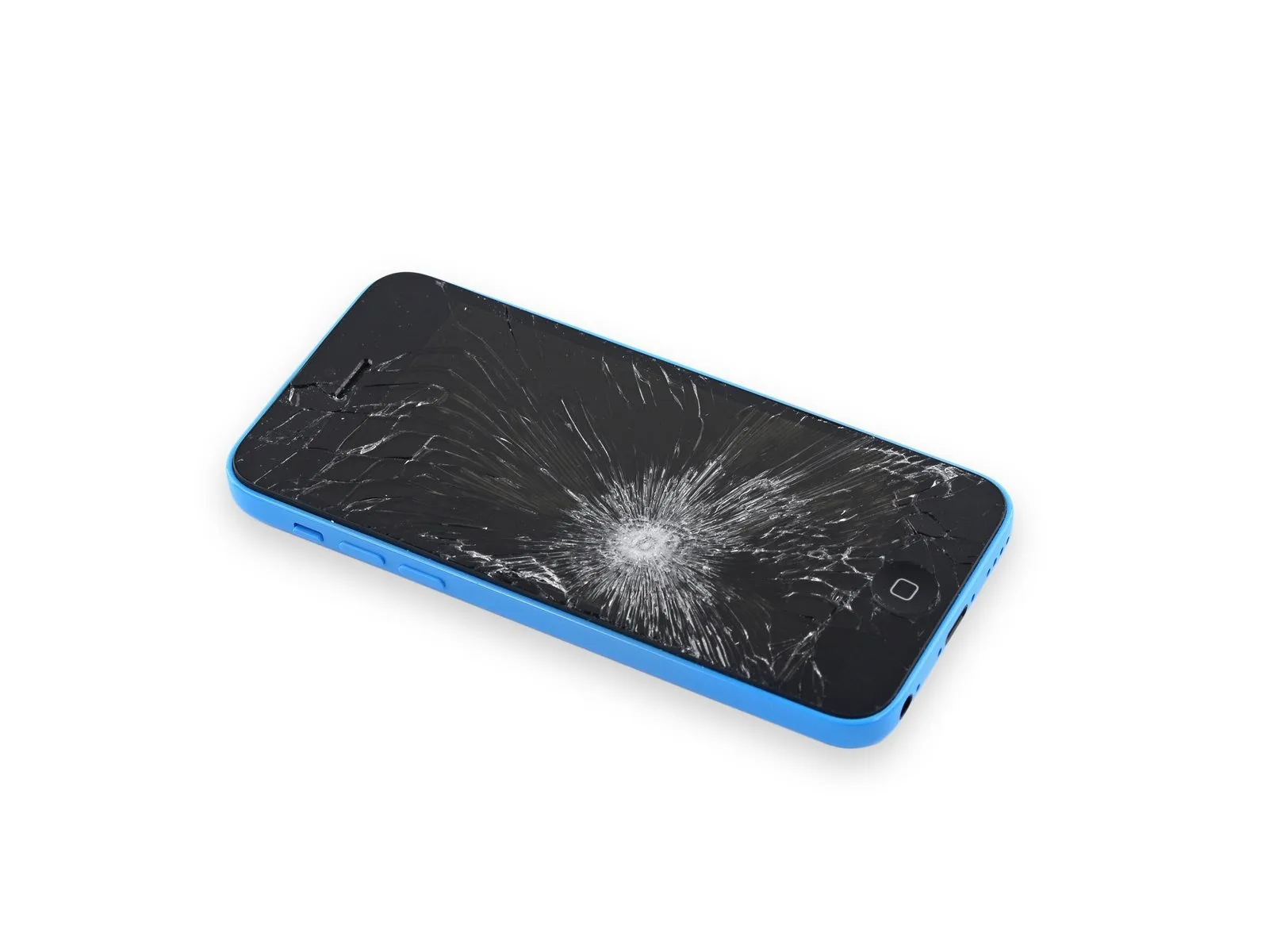
To mitigate the risk of additional shattering and potential injury while repairing a cracked display glass, secure it with tape.
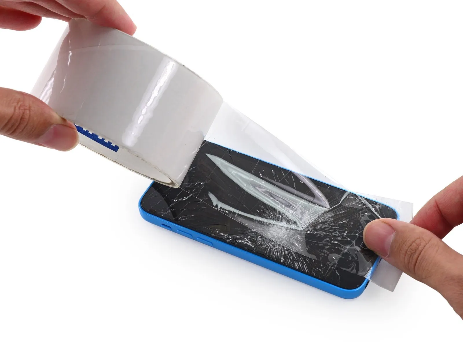
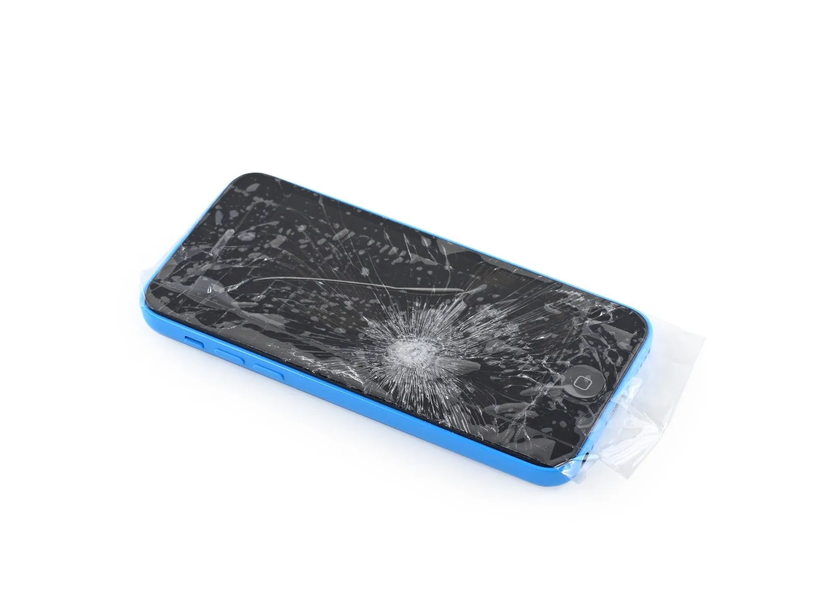
Apply strips of transparent packing tape across the iPhone screen, ensuring complete coverage by layering them.
To prevent glass fragments from scattering and to maintain the assembly's stability while separating and raising the screen, this step is crucial.
To safeguard your eyes from potential glass fragments that may detach during the repair process, always use safety glasses.
Step 2 | Removing the Pentalobe screws
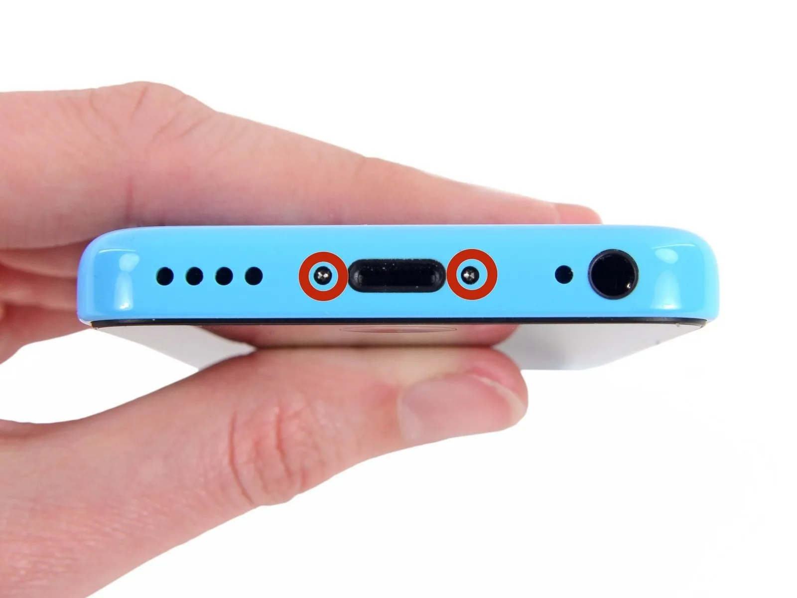
To prevent a potential fire or explosion hazard during repair, ensure the iPhone's lithium-ion battery is depleted to less than 25% capacity prior to beginning work; a fully charged battery poses a significant risk of combustion if damaged.
To prevent electrical shock or damage, ensure the iPhone is completely de-energized prior to starting the repair process.
Using appropriate tools, detach the two screws, each measuring 3.8 mm in diameter and featuring a P2 Pentalobe head, located on both sides of the Lightning connector.
To prevent electrical shock or damage, ensure the iPhone is completely de-energized prior to starting the repair process.
Using appropriate tools, detach the two screws, each measuring 3.8 mm in diameter and featuring a P2 Pentalobe head, located on both sides of the Lightning connector.
Step 3 | Starting the iSclack Opening Procedure
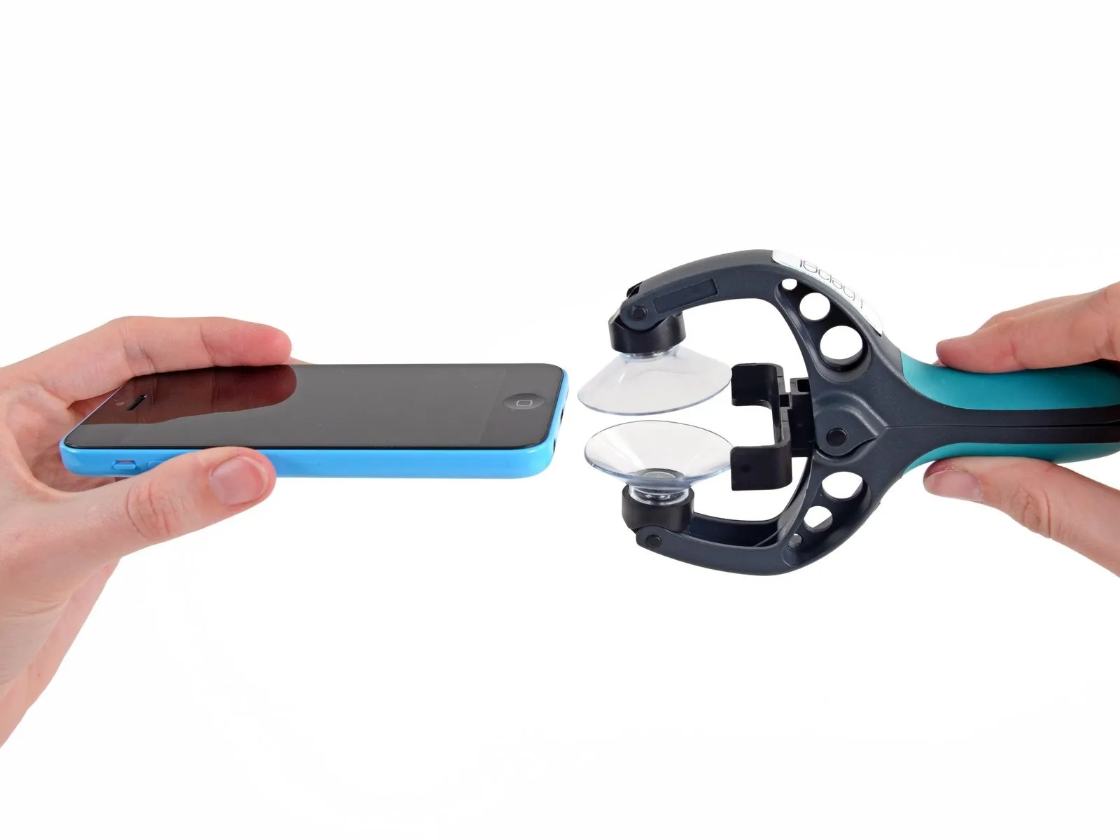

For those performing multiple iPhone 5, 5s, or 5c repairs, we suggest utilizing the iSclack to safely separate the device; the following two steps detail its use, but if you prefer an alternative method, proceed directly to Step 5.
Actuate the iSclack handle to release the clamping force of the suction-cup jaws.
Position the iPhone’s lower edge between the suction cups, ensuring it contacts the plastic depth gauge.
Position the uppermost suction cup so it hovers slightly above the home button.
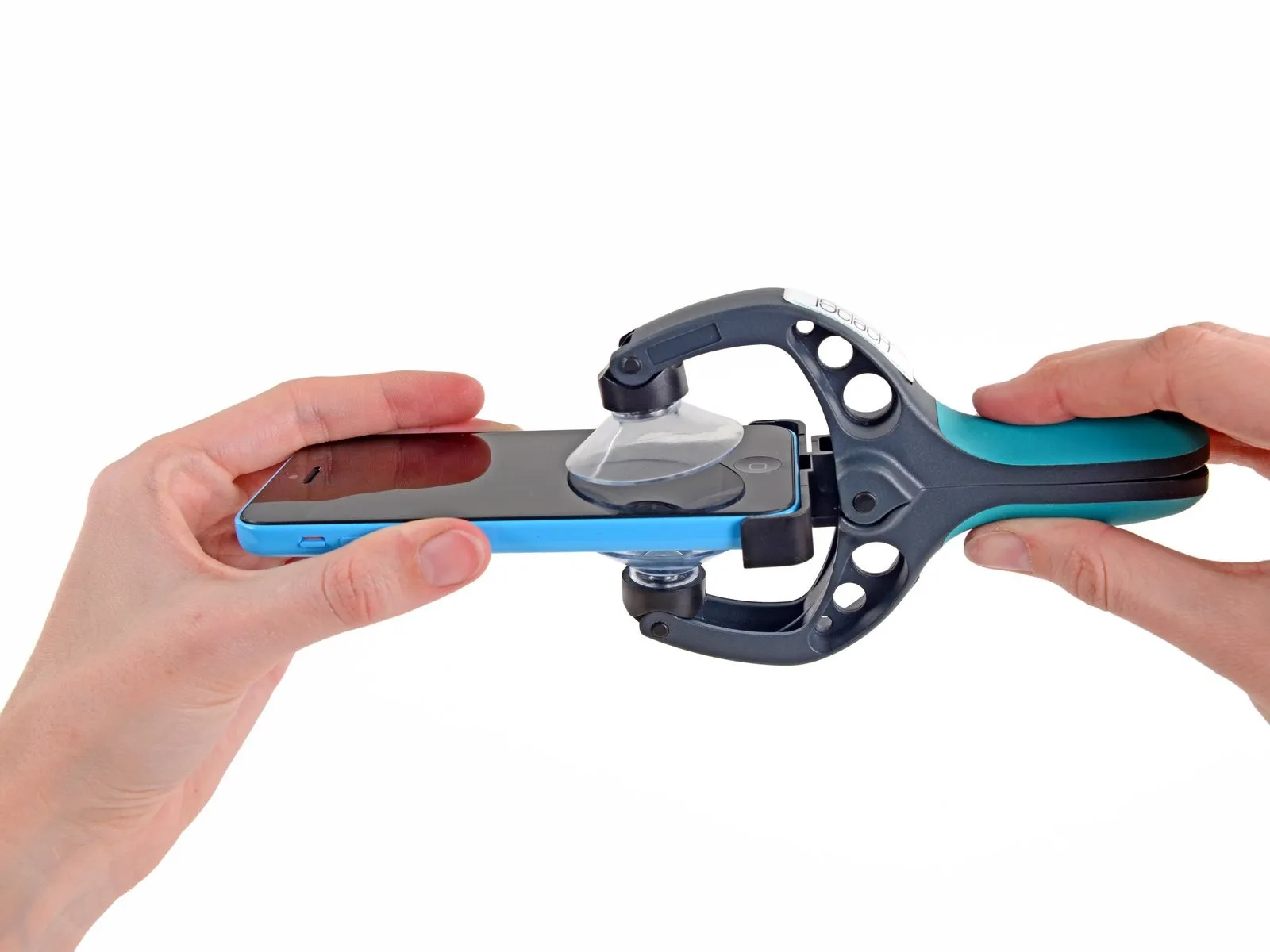
To secure the iPhone, position the iSclack's jaws closed by opening the handles. Align the suction cups centrally, then apply consistent, firm pressure to both the top and bottom surfaces of the device.
Actuate the iSclack handle to release the clamping force of the suction-cup jaws.
Position the iPhone’s lower edge between the suction cups, ensuring it contacts the plastic depth gauge.
Position the uppermost suction cup so it hovers slightly above the home button.
To secure the iPhone, position the iSclack's jaws closed by opening the handles. Align the suction cups centrally, then apply consistent, firm pressure to both the top and bottom surfaces of the device.
Step 4 | Finishing the iSclack Opening Procedure
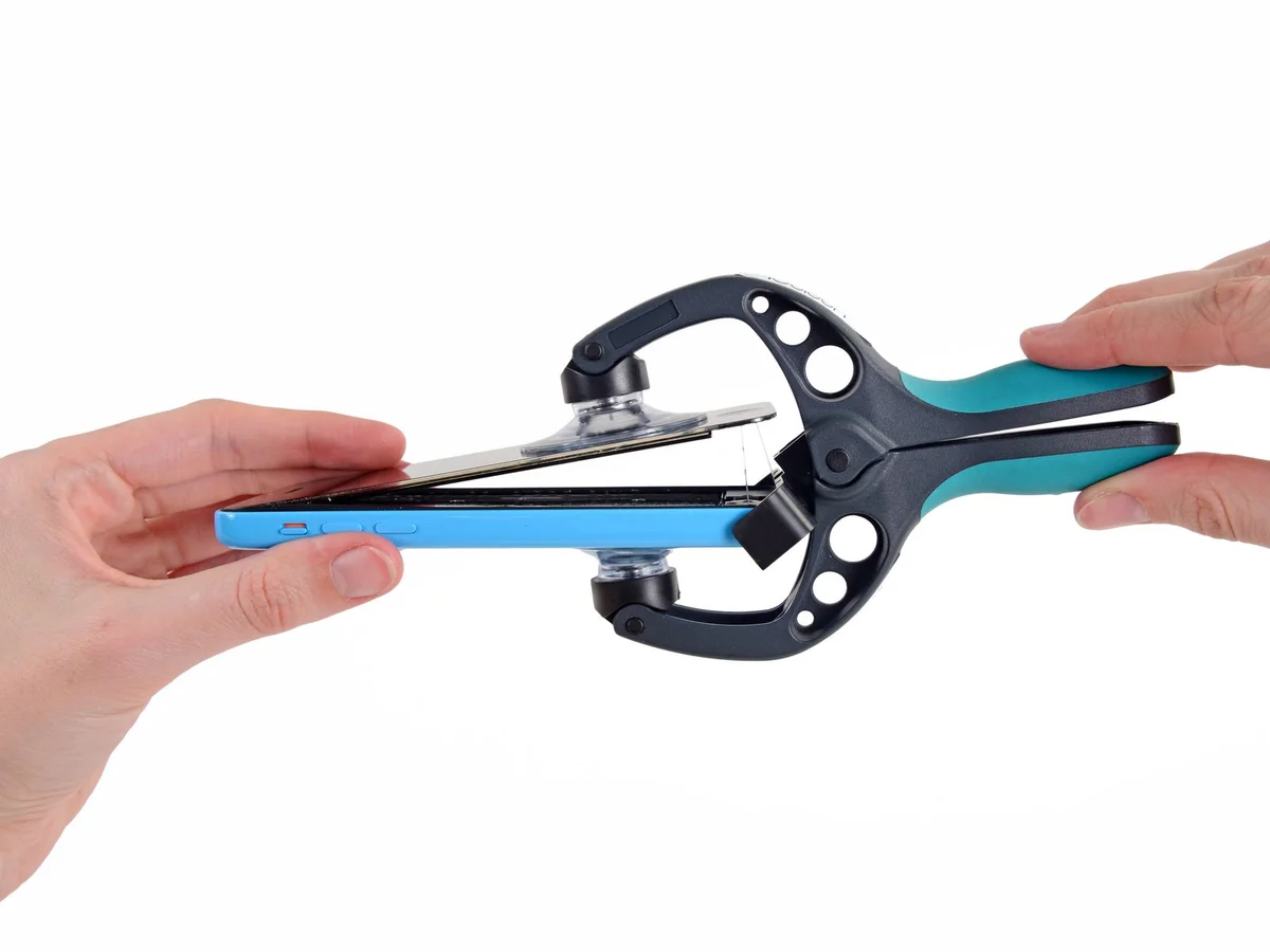
Using a firm grip on the iPhone, disengage the iSclack's handle to release the suction cups, then lift the front panel away from the rear enclosure.
This specialized tool allows for a controlled separation of the iPhone's components, facilitating repair work while preventing cable damage, as it only opens the device to the necessary degree.
Detach the iPhone from its mounting surface by removing both suction cups.
Proceed directly to Step 8, bypassing the subsequent three steps.
Step 5 | Manual Opening Procedure
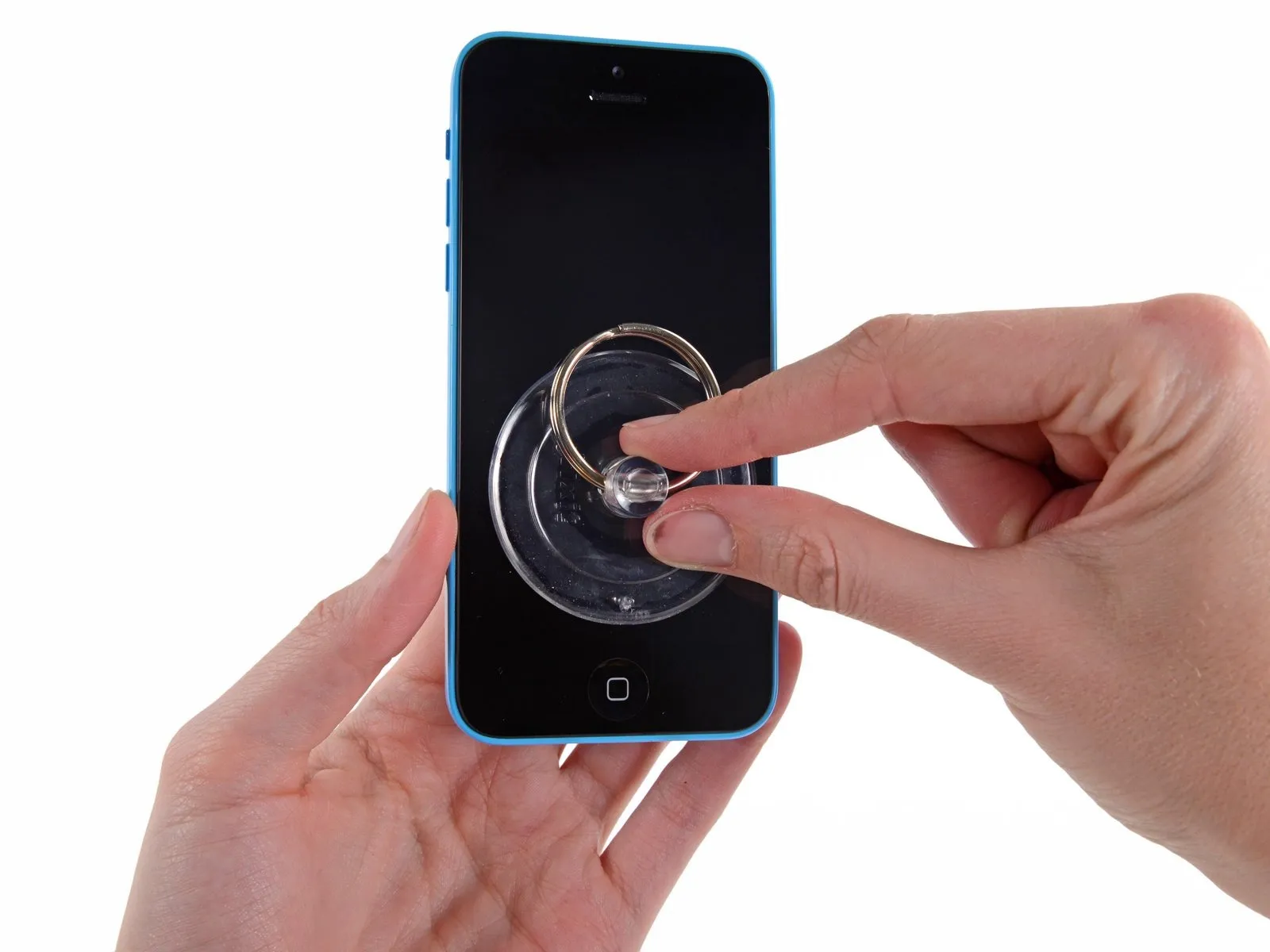
Position a suction cup directly on the display surface, located immediately above the home button.
Ensure the cup's entire surface makes full contact with the display to guarantee a secure connection.
Ensure the cup's entire surface makes full contact with the display to guarantee a secure connection.
Step 6 | Start lifting the front panel assembly
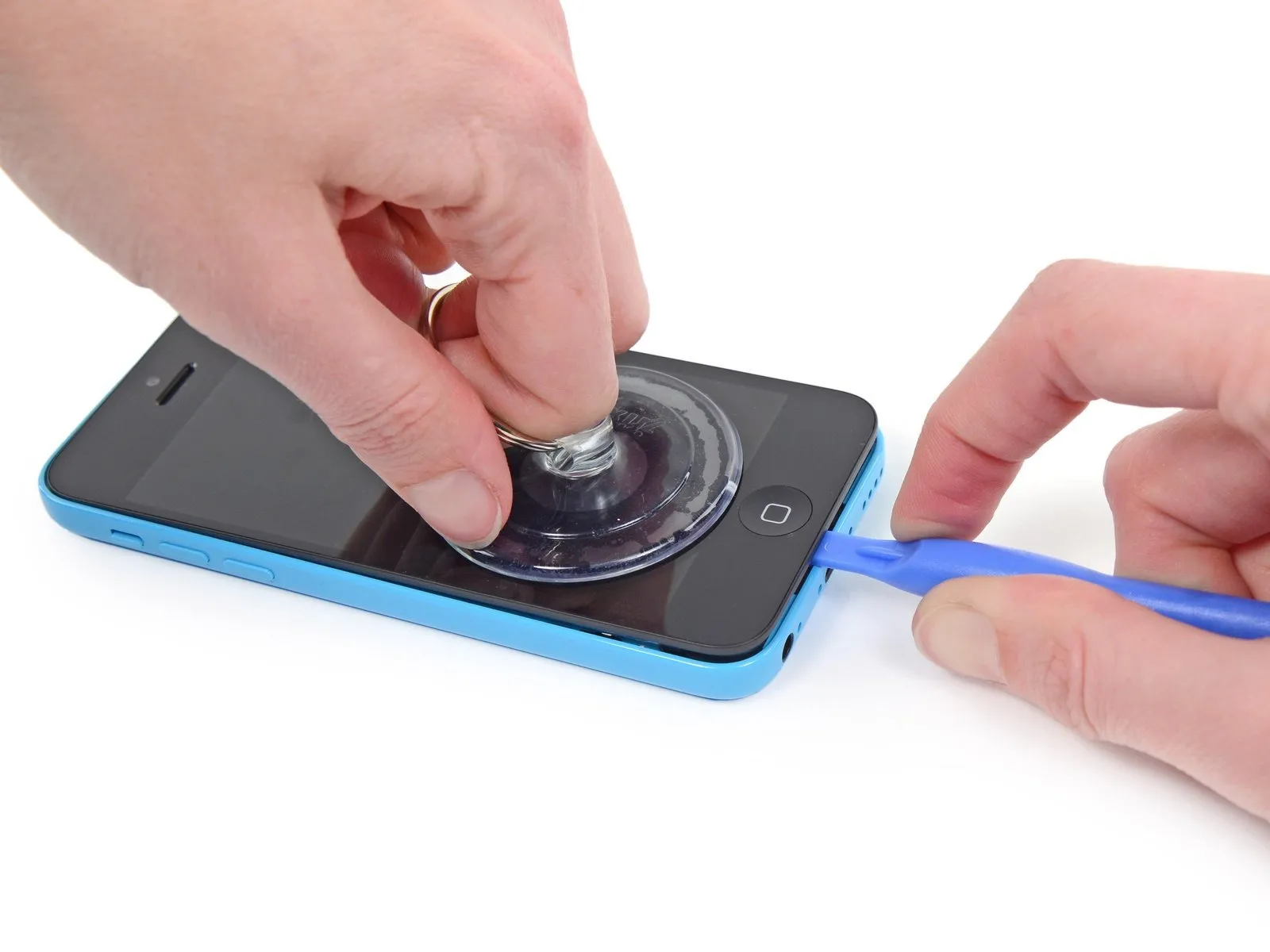
Secure the front panel assembly to the suction cup, ensuring a strong bond.
Using one hand to secure the iPhone, lift the suction cup vertically to create a small gap between the front panel and the rear enclosure.
Exercise caution and use steady, even pressure when installing the display assembly, as its fit is significantly more snug than typical device components.
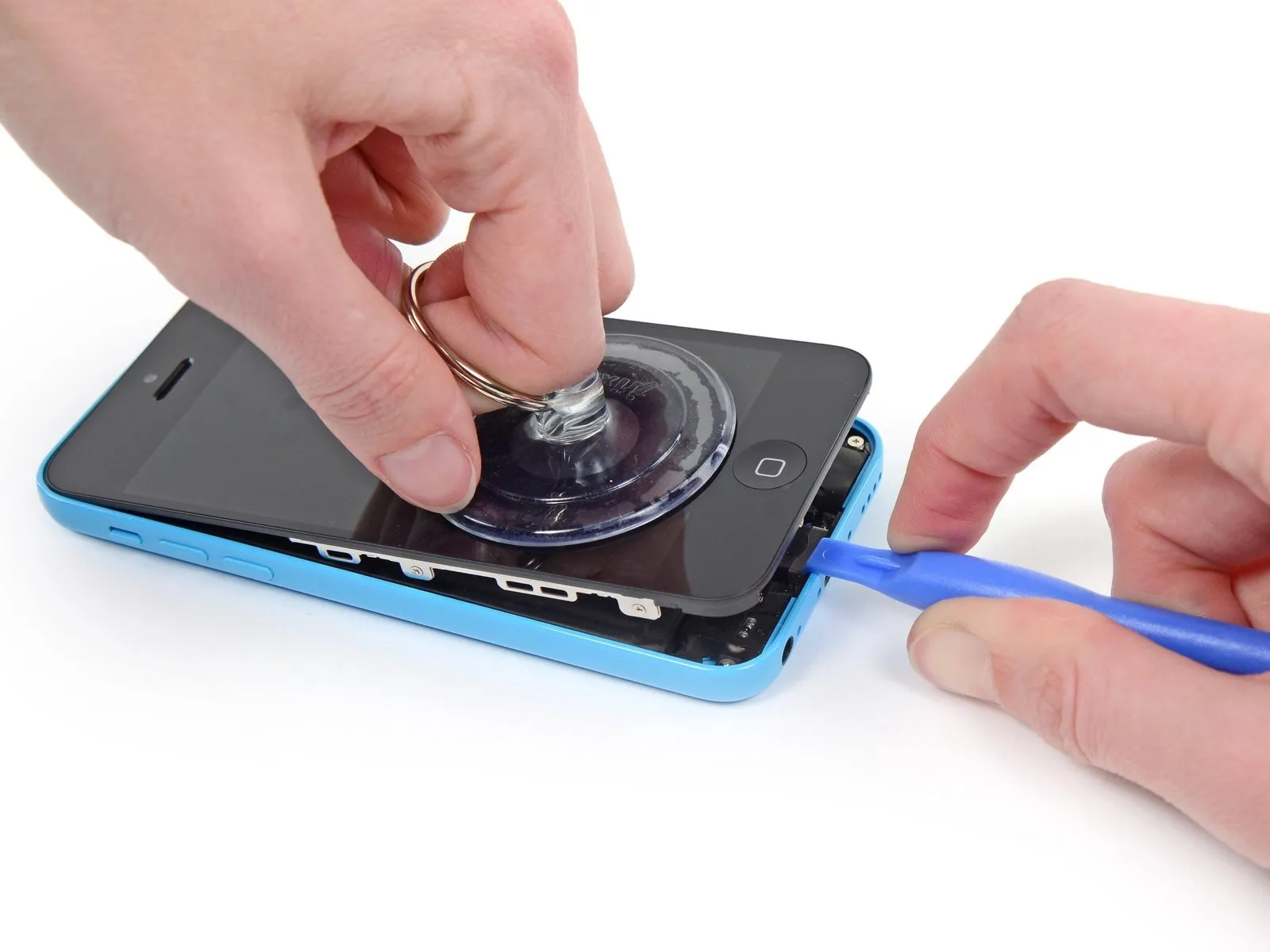
Using a plastic opening tool, carefully separate the rear case from the display assembly by gently levering it upwards, simultaneously applying upward traction with the suction cup.
To release the front panel assembly from the rear case, carefully disengage the multiple retaining clips, employing both the suction cup and plastic opening tool as needed.
Using one hand to secure the iPhone, lift the suction cup vertically to create a small gap between the front panel and the rear enclosure.
Exercise caution and use steady, even pressure when installing the display assembly, as its fit is significantly more snug than typical device components.
Using a plastic opening tool, carefully separate the rear case from the display assembly by gently levering it upwards, simultaneously applying upward traction with the suction cup.
To release the front panel assembly from the rear case, carefully disengage the multiple retaining clips, employing both the suction cup and plastic opening tool as needed.
Step 7
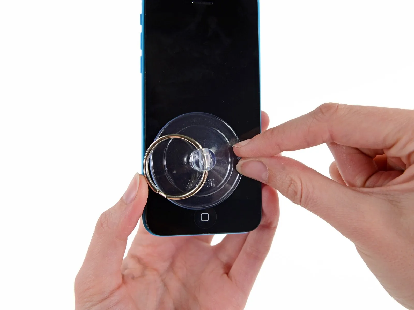
To detach the suction cup, depress the plastic projection to break the airtight seal.
Detach the display assembly's suction cup.
Detach the display assembly's suction cup.
Step 8 | Opening up the phone
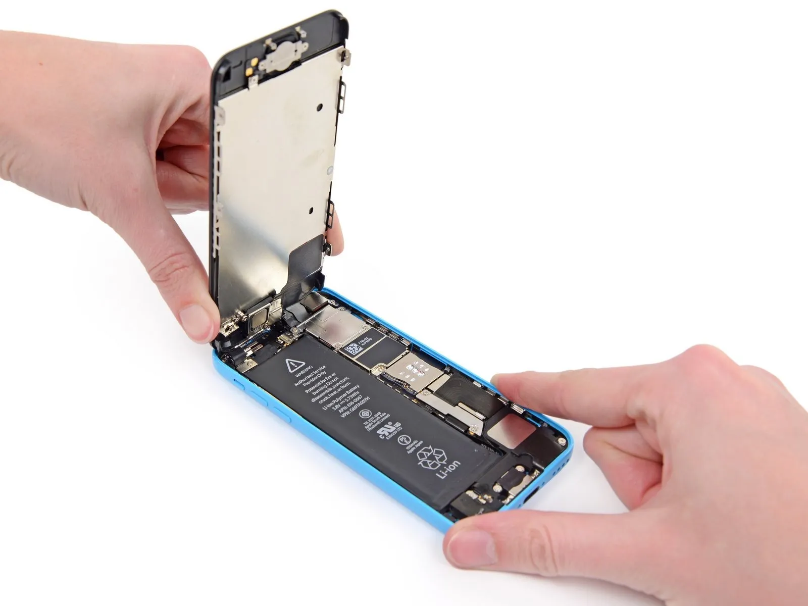
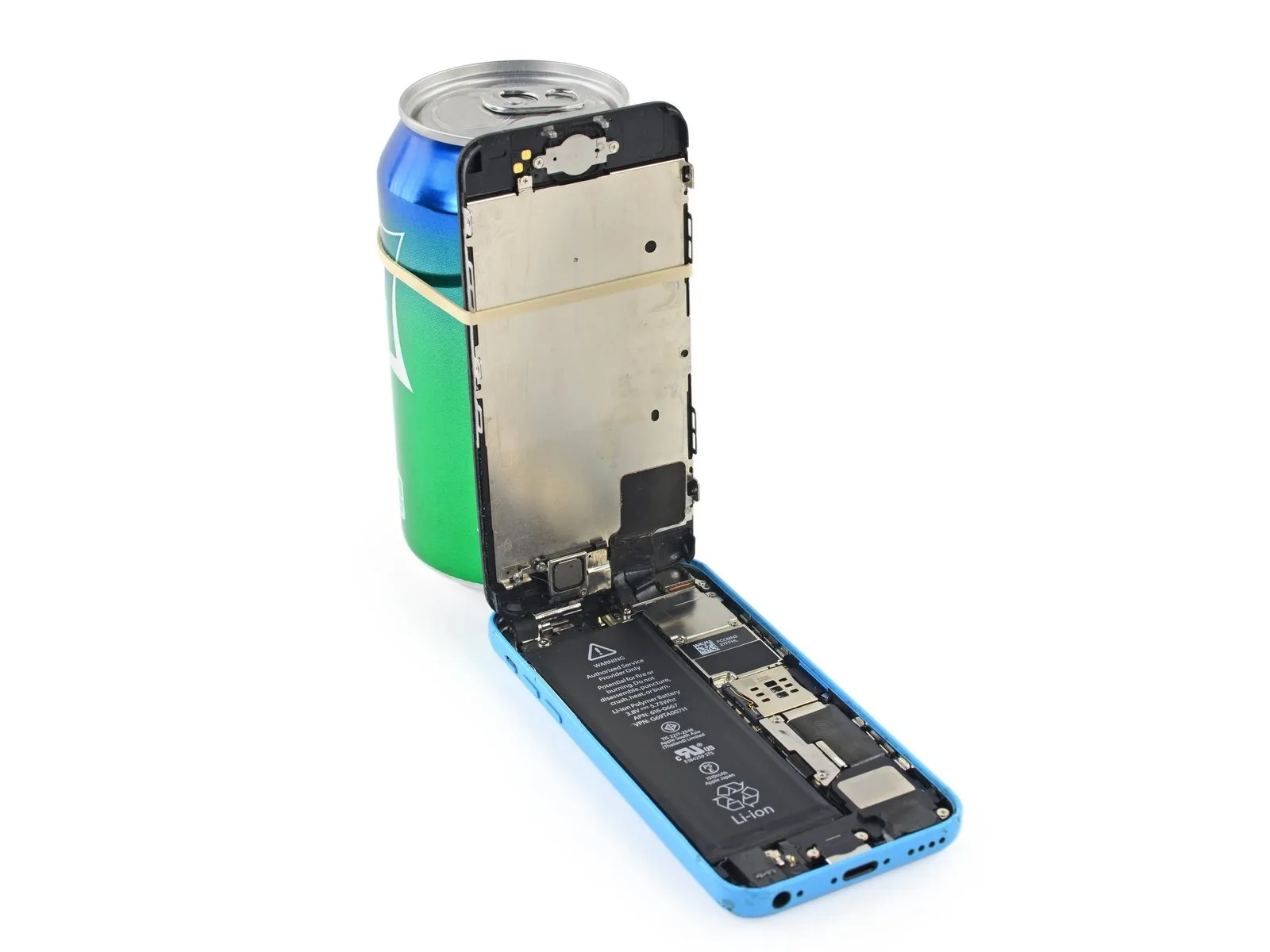
To expose the connectors located at the top edge of the device, gently raise the front panel, beginning at the home button end.
Carefully position the display at a roughly 90-degree angle, then secure it in place using a support to prevent movement during the repair process.
As a temporary substitute, an unopened standard-sized canned drink can be employed to secure the display in place.
To avoid stressing the display's wiring during the repair process, secure it with a rubber band.
Step 9
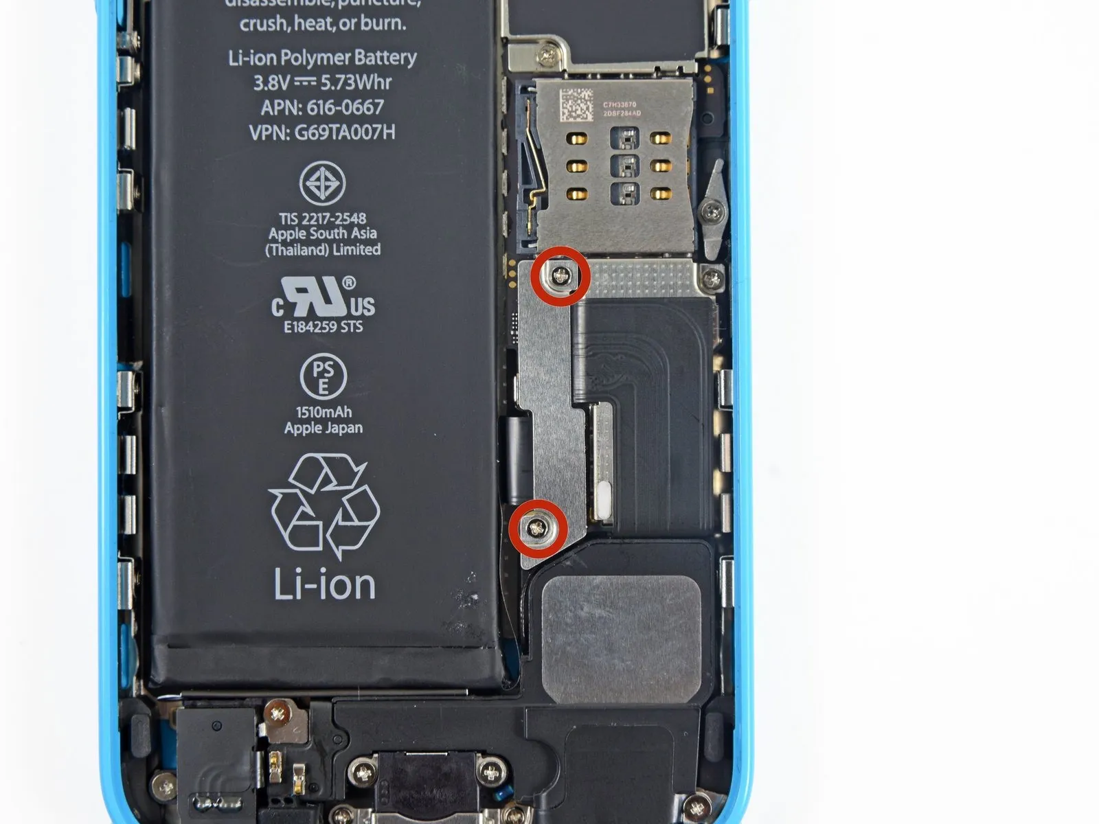
Using a Phillips #000 screwdriver, detach the metal bracket that holds the battery connector by unscrewing the two 1.6 mm screws it uses to fasten to the logic board.
Step 10

Detach the bracket securing the battery connector using a tri-point screwdriver.
Step 11 | Disconnecting the battery connector

Carefully lift the battery connector away from its corresponding socket on the logic board, employing a spudger or a clean fingernail to avoid damage.
Exercise extreme caution during the lifting process, ensuring you apply force solely to the battery connector; avoid any pressure on the logic board socket or the board's surface, as this could result in socket damage or harm to adjacent components.
Exercise extreme caution during the lifting process, ensuring you apply force solely to the battery connector; avoid any pressure on the logic board socket or the board's surface, as this could result in socket damage or harm to adjacent components.
Step 12

Using a Phillips #000 screwdriver, detach the bracket that holds the front panel assembly cable by unscrewing the screws fastening it to the logic board.
Use two screws, each measuring 1.3 millimeters.
A single screw, measuring 1.7 millimeters, is required.
A screw with a 3.25 mm diameter is required.
Carefully manage all screws during this stage to ensure correct reassembly; improper screw selection, such as using a 3.25 mm screw or a 1.7 mm screw in the bottom right hole, will critically damage the logic board and prevent the device from powering on.
Avoid applying excessive force when tightening screws; if resistance is encountered during installation, verify that the correct screw size is being used and do not force the fastener.
Step 13
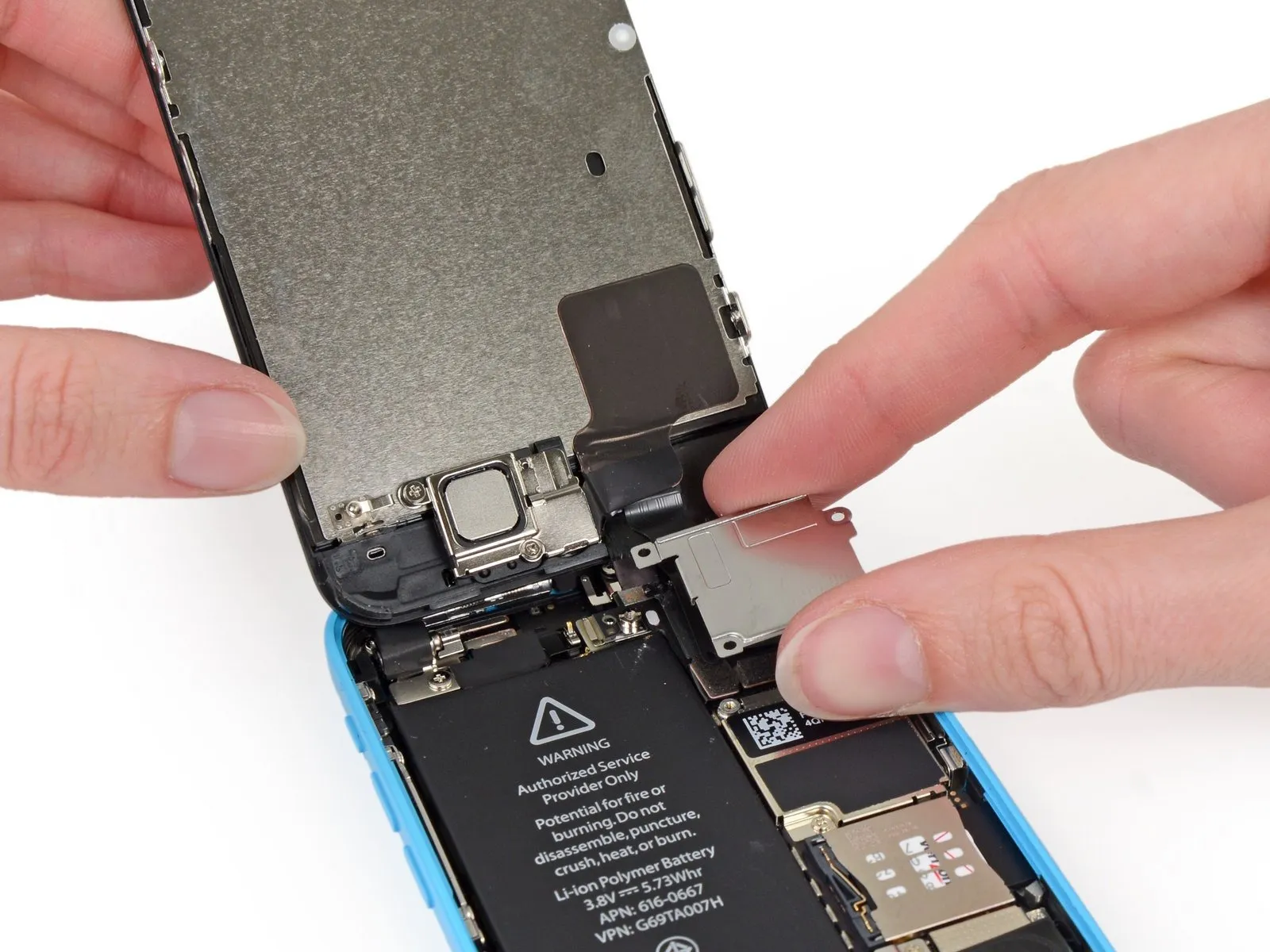
Detach the cable bracket securing the front panel assembly wiring harness to the logic board.
Step 14 | Disconnecting the front panel assembly cables

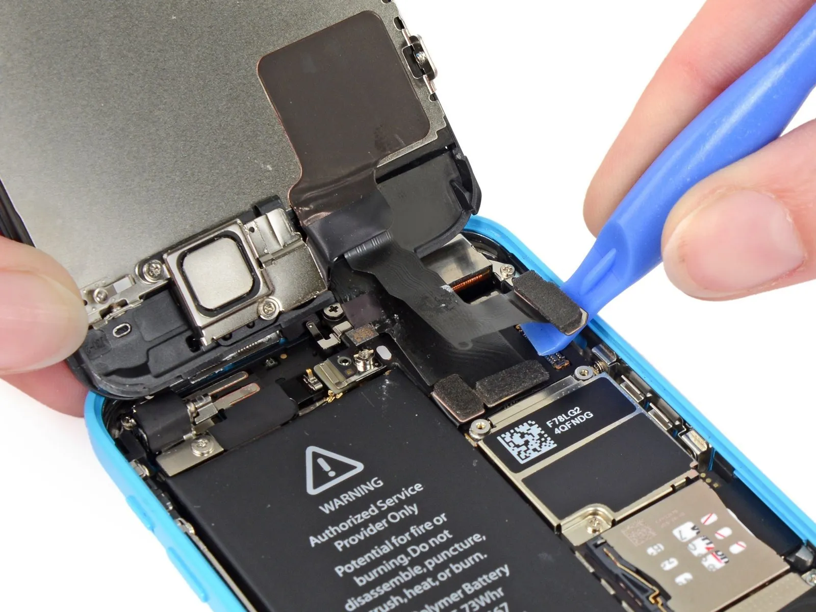
Carefully detach the front camera and sensor cable connector from its socket using a plastic pry tool or your fingernail.
Avoid applying lifting force to the logic board socket itself; direct your prying action solely to the connector.
Avoid applying lifting force to the logic board socket itself; direct your prying action solely to the connector.
Step 15

Prior to either detaching or reattaching the cables in this procedure, ensure the battery is disconnected.
Carefully separate the LCD cable connector from its socket using a plastic pry tool or your fingernail.
Because the LCD and Digitizer connectors are joined within a single cable harness, lifting the LCD connector will simultaneously release both connections. Ensure complete separation of the two cables prior to display removal.
A disconnected LCD cable from its connector during reassembly can result in a blank screen or white lines; to resolve this, ensure the cable is securely attached and restart the device by briefly removing and reinstalling the battery.
Step 16 | Separating front panel assembly and rear case

Detach the front panel assembly from the rear case.
Step 17 | Home Button Ribbon Cable
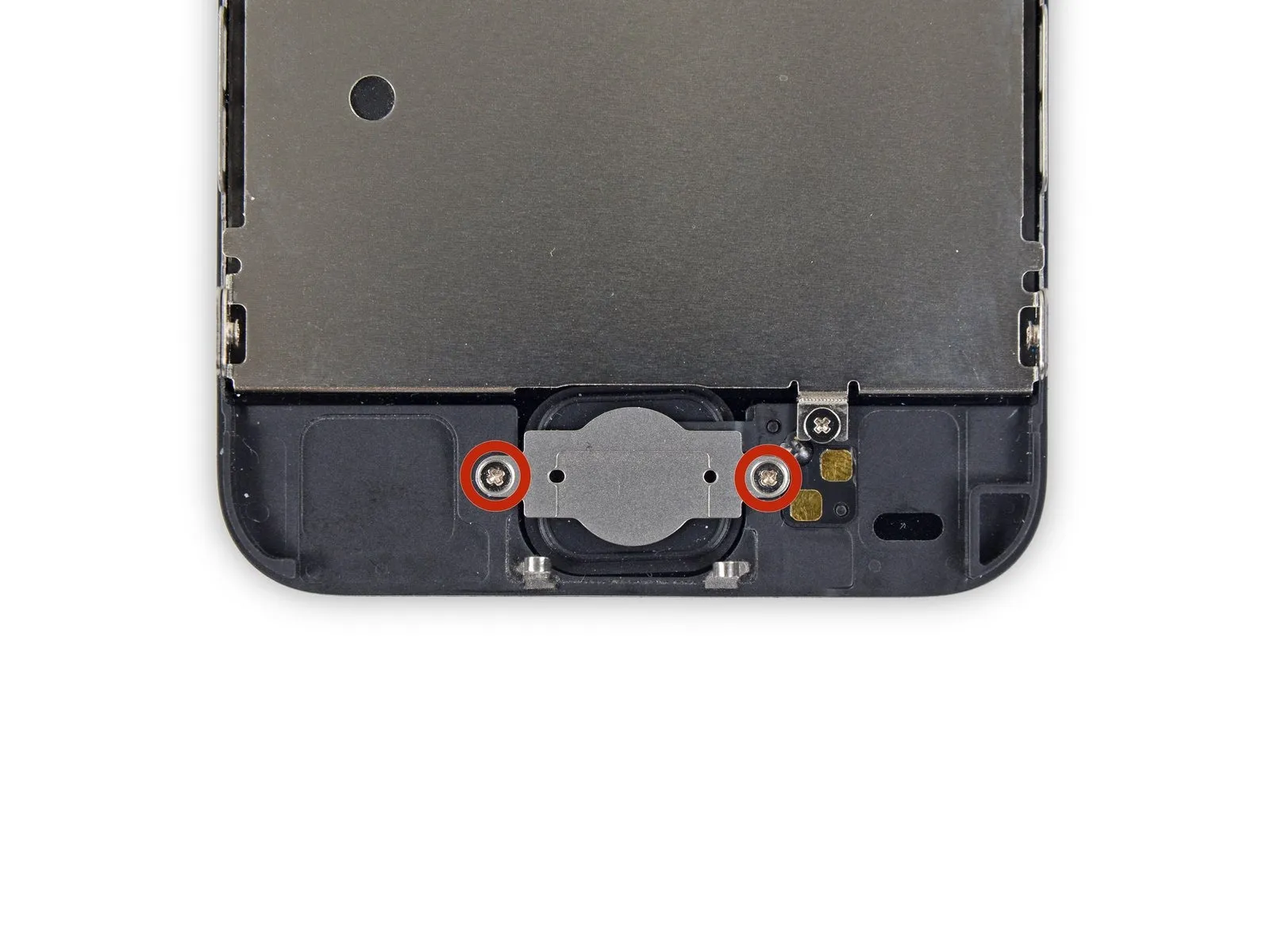
Using a Phillips #000 screwdriver, detach the home button bracket from the display assembly by unscrewing the two fasteners, each measuring 1.3 mm.
Step 18

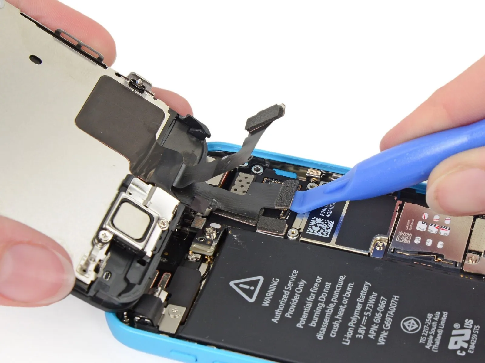
Carefully lift the home button ribbon cable's edge away from the display assembly using a plastic opening tool.
Commence the repair process beginning with the right-side contact points, proceeding sequentially toward the left.
To avoid damaging the ribbon cable, begin at the left edge and proceed rightward, carefully lifting the front panel to release the firmly attached contacts.
To facilitate tool insertion beneath the contact points if needed, reverse the tool's orientation and apply gentle pressure to the right side of the contact cable to release any adhesive, then attempt sliding the tool again.
Step 19

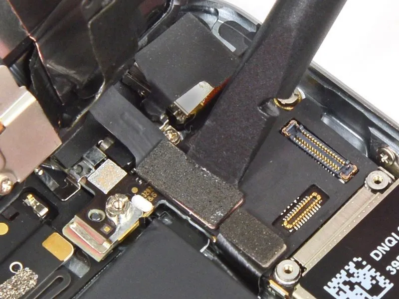
Carefully disconnect the ribbon cable connecting the home button to the display assembly.
During reassembly when replacing the home button ribbon cable, the metal bracket must be moved to the new cable.
During reassembly when replacing the home button ribbon cable, the metal bracket must be moved to the new cable.
Step 20 | Home Button


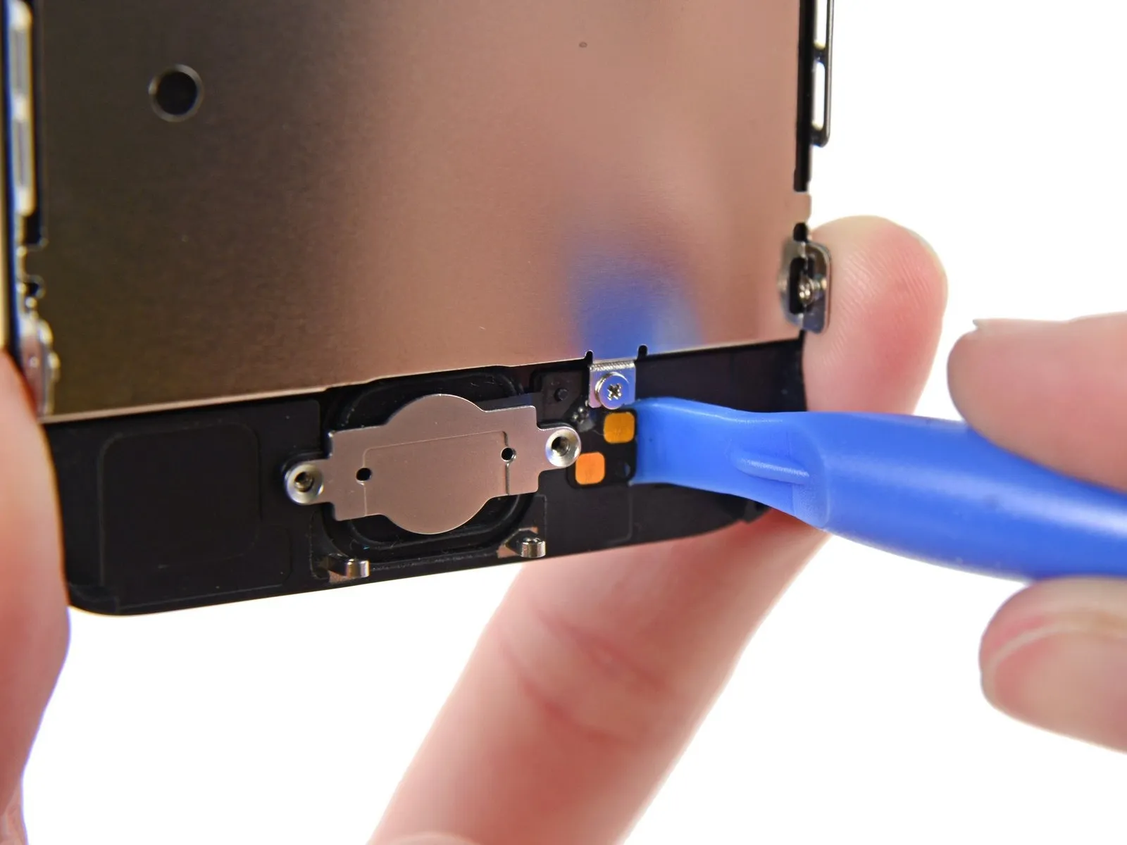
Using careful, even pressure, lift the upper-right portion of the home button, separating it from the display assembly.
To release the home button, depress it slightly, just enough to create a gap allowing for separation with a spudger.
Due to its delicate nature, the membrane is prone to damage; should you perceive a risk of tearing while handling it, gently apply heat and attempt the process once more.
To release the home button, depress it slightly, just enough to create a gap allowing for separation with a spudger.
Due to its delicate nature, the membrane is prone to damage; should you perceive a risk of tearing while handling it, gently apply heat and attempt the process once more.
Step 21

Using a spudger, carefully separate the remaining adhesive securing the home button from the display surface.
Step 22

Carefully detach the home button assembly from the front panel.