iPhone 5c Battery Replacement
If your iPhone 5c's battery is depleting rapidly or failing to maintain a charge as it once did, follow these instructions to substitute it.
Due to the potential for hazards, handle a battery exhibiting swelling with extreme care.
- To safeguard the display cables, proceed with disassembling the front panel assembly as detailed in this guide.
- For those experienced with handling delicate components, you may choose to forgo detaching the display panel; instead, proceed directly to the battery disconnection process, ensuring you provide stable support to the display during battery extraction.
To ensure peak functionality, following the steps in this guide, perform a battery calibration: Initially, fully charge the battery and continue charging for a minimum of two additional hours. Subsequently, deplete the battery completely by using your iPhone until it powers down. Lastly, recharge the battery to 100% without interruption.
Step 1 | Taping the display glass
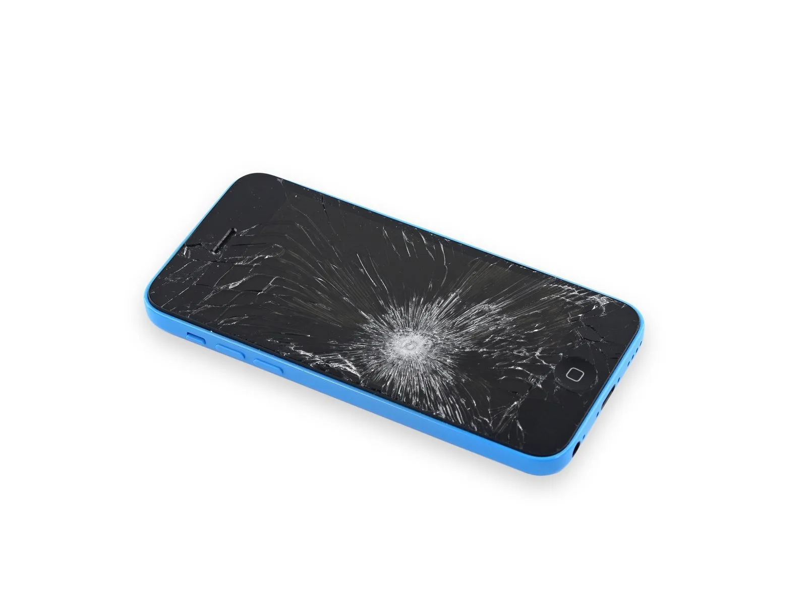
To mitigate the risk of additional shattering and potential injury while repairing a cracked display glass, secure the glass with tape.
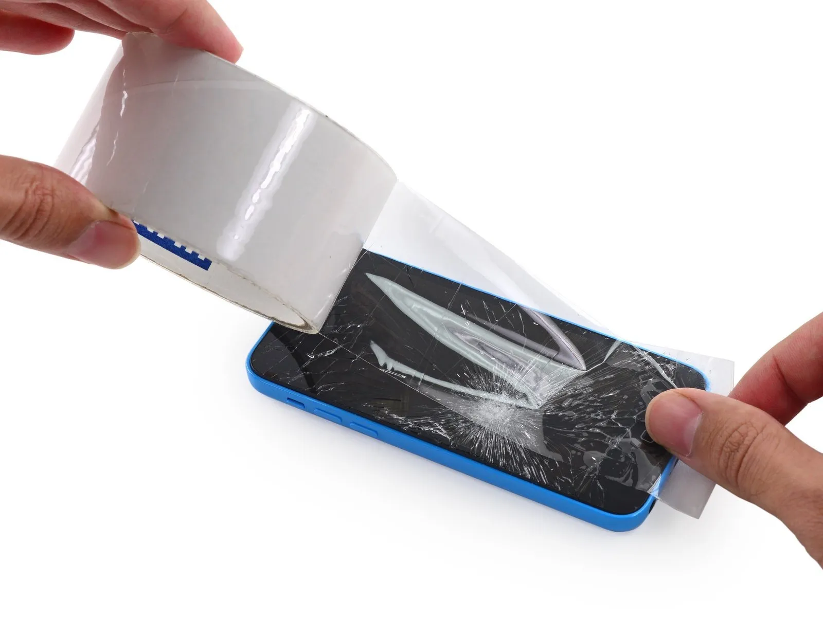
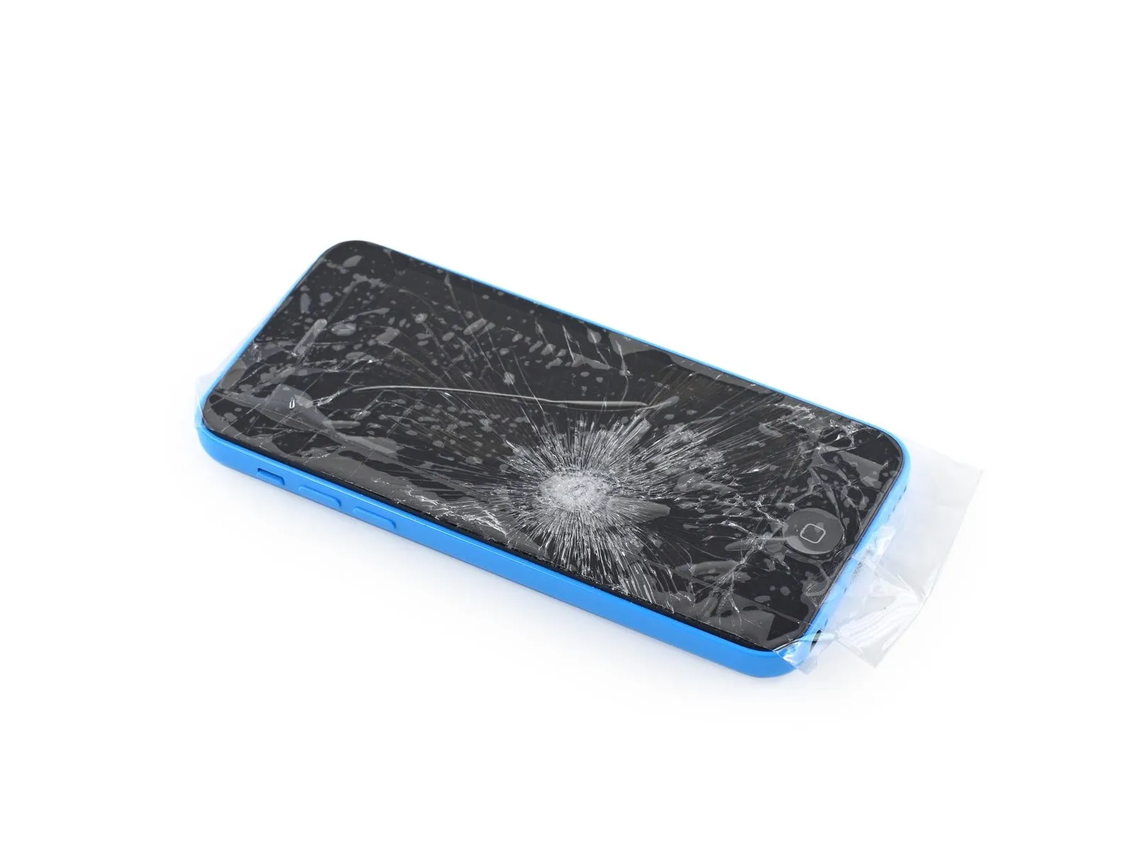
Apply strips of transparent packing tape across the iPhone screen, ensuring complete coverage by slightly overlapping each successive strip.
To prevent glass fragments from scattering and maintain stability during the display separation process, this technique is essential.
To safeguard your eyes from potential glass fragments released during the repair process, always use safety glasses.
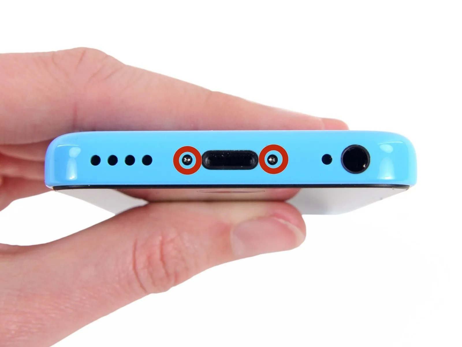
Step 2 | Removing the Pentalobe screws
To prevent a potential fire or explosion hazard during repair, ensure the iPhone's lithium-ion battery is depleted to less than 25% capacity prior to beginning work; a fully charged battery poses a significant risk of ignition or rupture if damaged.
To prevent electrical shock or damage, ensure the iPhone is completely de-energized prior to starting the repair process.
Using appropriate tools, detach the two P2 Pentalobe screws, each measuring 3.8 mm, located on both sides of the Lightning connector.
To prevent electrical shock or damage, ensure the iPhone is completely de-energized prior to starting the repair process.
Using appropriate tools, detach the two P2 Pentalobe screws, each measuring 3.8 mm, located on both sides of the Lightning connector.
Step 3 | Starting the iSclack Opening Procedure

For those performing multiple iPhone 5, 5s, or 5c repairs, we suggest utilizing the iSclack to ensure safe separation of the device; if you are not employing this tool, proceed directly to Step 5.
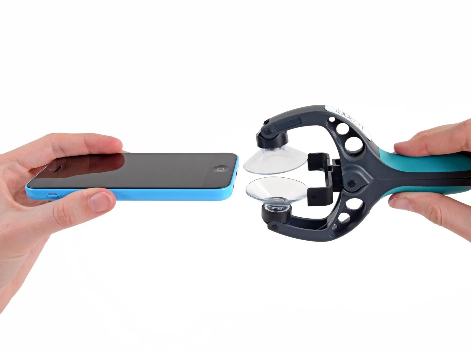
Actuate the iSclack handle to release the clamping force of the suction-cup jaws.
Position the iPhone's lower edge between the suction cups, ensuring it contacts the plastic depth gauge.
Position the uppermost suction cup so it hovers slightly above the home button.
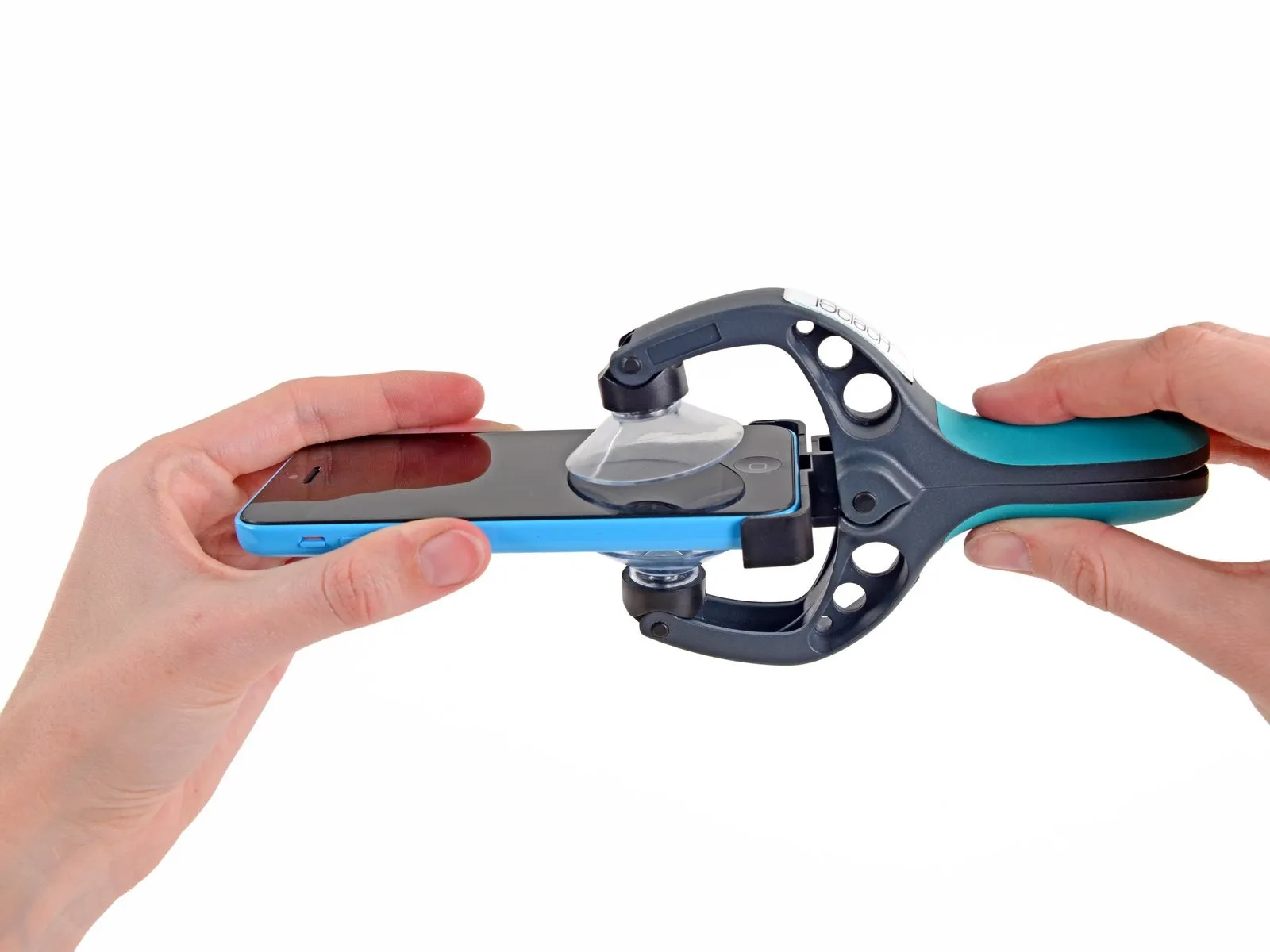
To secure the iPhone, position the suction cups centrally and apply consistent, strong pressure to both the upper and lower surfaces, ensuring the iSclack jaws are closed by manipulating the handles.
Actuate the iSclack handle to release the clamping force of the suction-cup jaws.
Position the iPhone's lower edge between the suction cups, ensuring it contacts the plastic depth gauge.
Position the uppermost suction cup so it hovers slightly above the home button.
To secure the iPhone, position the suction cups centrally and apply consistent, strong pressure to both the upper and lower surfaces, ensuring the iSclack jaws are closed by manipulating the handles.
Step 4 | Finishing the iSclack Opening Procedure
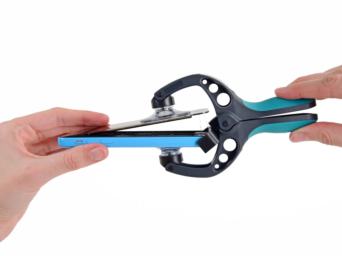
Using a firm grip on the iPhone, release the iSclack's handle to disengage the suction cups and lift the front panel away from the rear enclosure.
This specialized opening tool allows for controlled separation of the iPhone's components, preventing cable damage while maintaining structural integrity.
Detach the iPhone from its mounting surface by removing both suction cups.
Proceed directly to Step 8, bypassing the subsequent three steps.
This specialized opening tool allows for controlled separation of the iPhone's components, preventing cable damage while maintaining structural integrity.
Detach the iPhone from its mounting surface by removing both suction cups.
Proceed directly to Step 8, bypassing the subsequent three steps.
Step 5 | Manual Opening Procedure
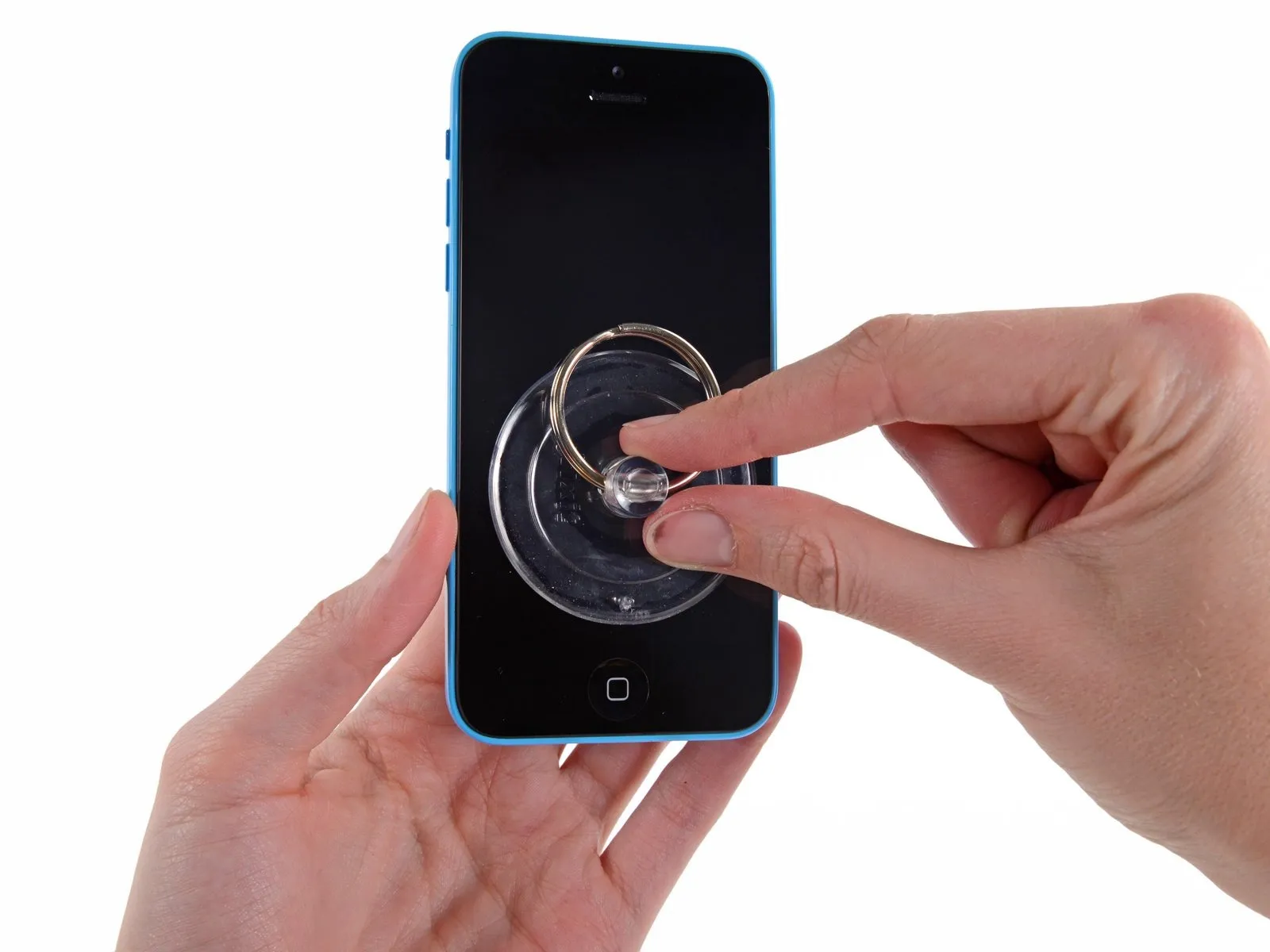
Using a suction cup, apply it to the display surface, positioning it directly over the home button area.
Ensure the screen’s entire surface is covered by the cup to guarantee a secure connection.
Ensure the screen’s entire surface is covered by the cup to guarantee a secure connection.
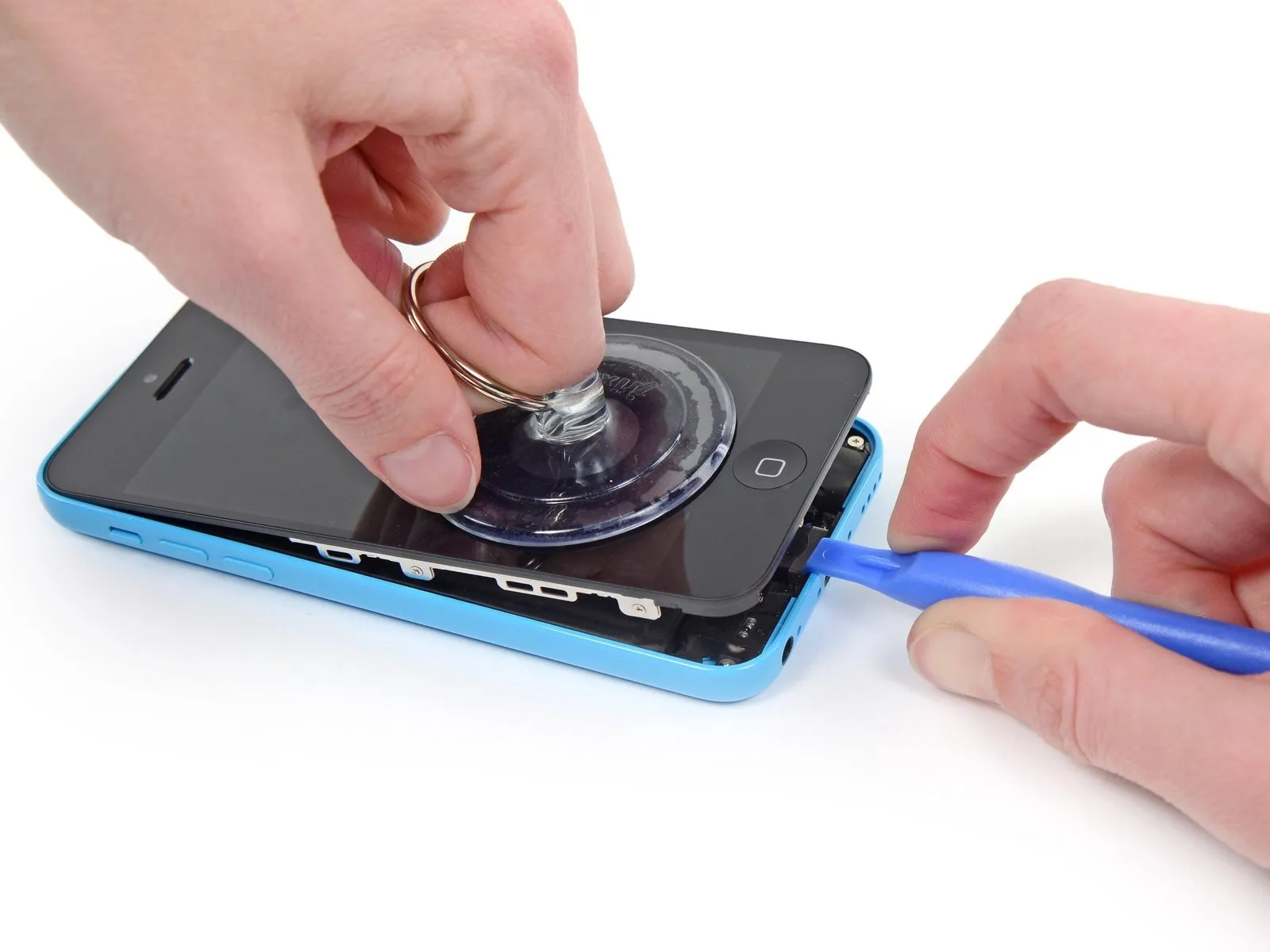
Step 6 | Start lifting the front panel assembly
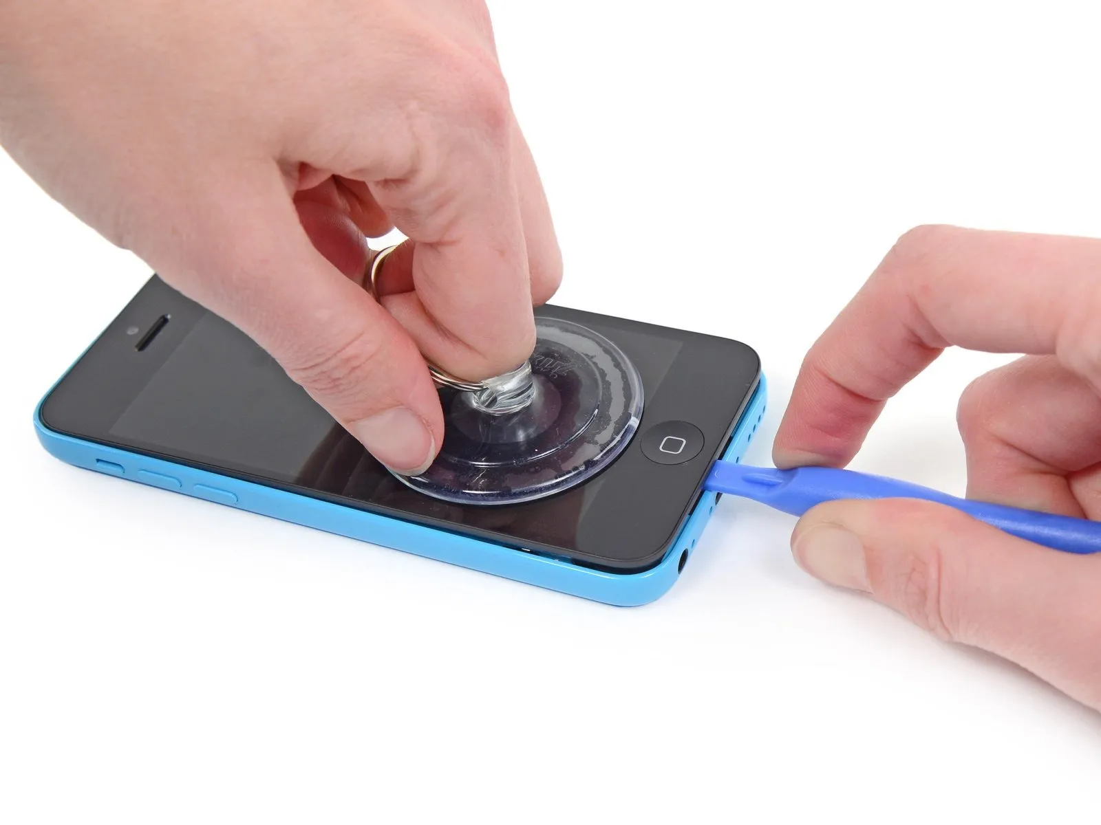
Securely affix the suction cup to the front panel assembly to ensure a stable connection.
Using one hand to secure the iPhone, gently lift the suction cup to create a small gap between the front panel and the device's back cover.
Exercise caution and use steady, even pressure when installing the display assembly, as its tolerances are significantly less forgiving than those typically found in other devices.
Using a plastic opening tool, carefully separate the rear case from the display assembly by gently levering it upwards, simultaneously lifting with a suction cup.
To release the front panel assembly from the rear case, carefully disengage the multiple retaining clips, employing both the suction cup and plastic opening tool as needed.
Step 7
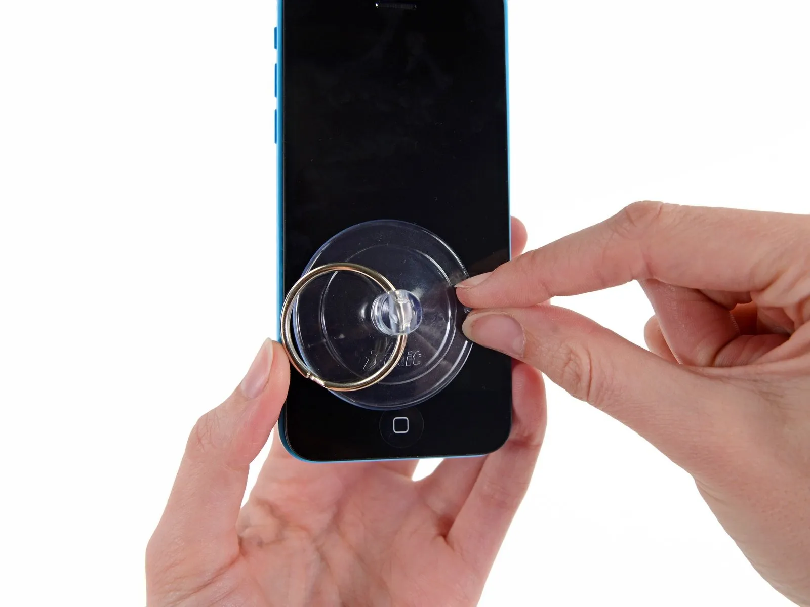
To detach the suction cup, depress the plastic projection to break the airtight seal.
Detach the display assembly's suction cup.
Detach the display assembly's suction cup.
Step 8 | Opening up the phone
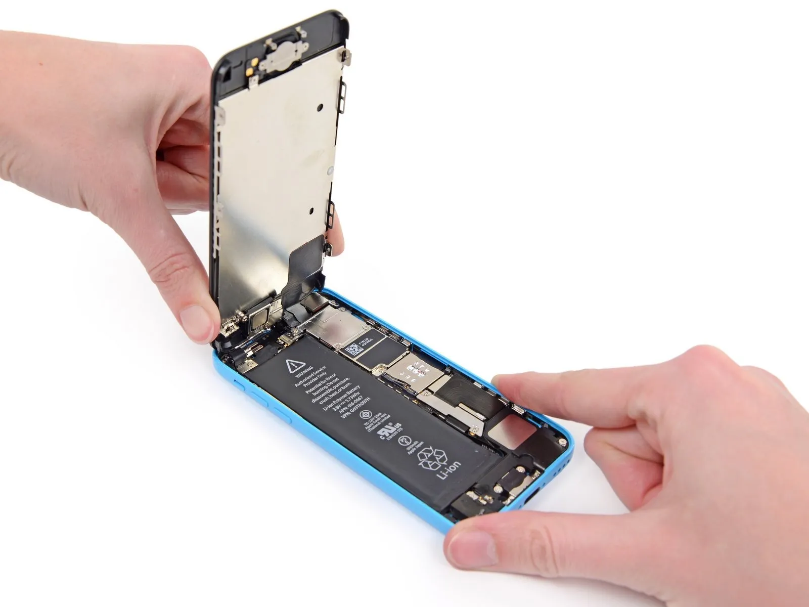
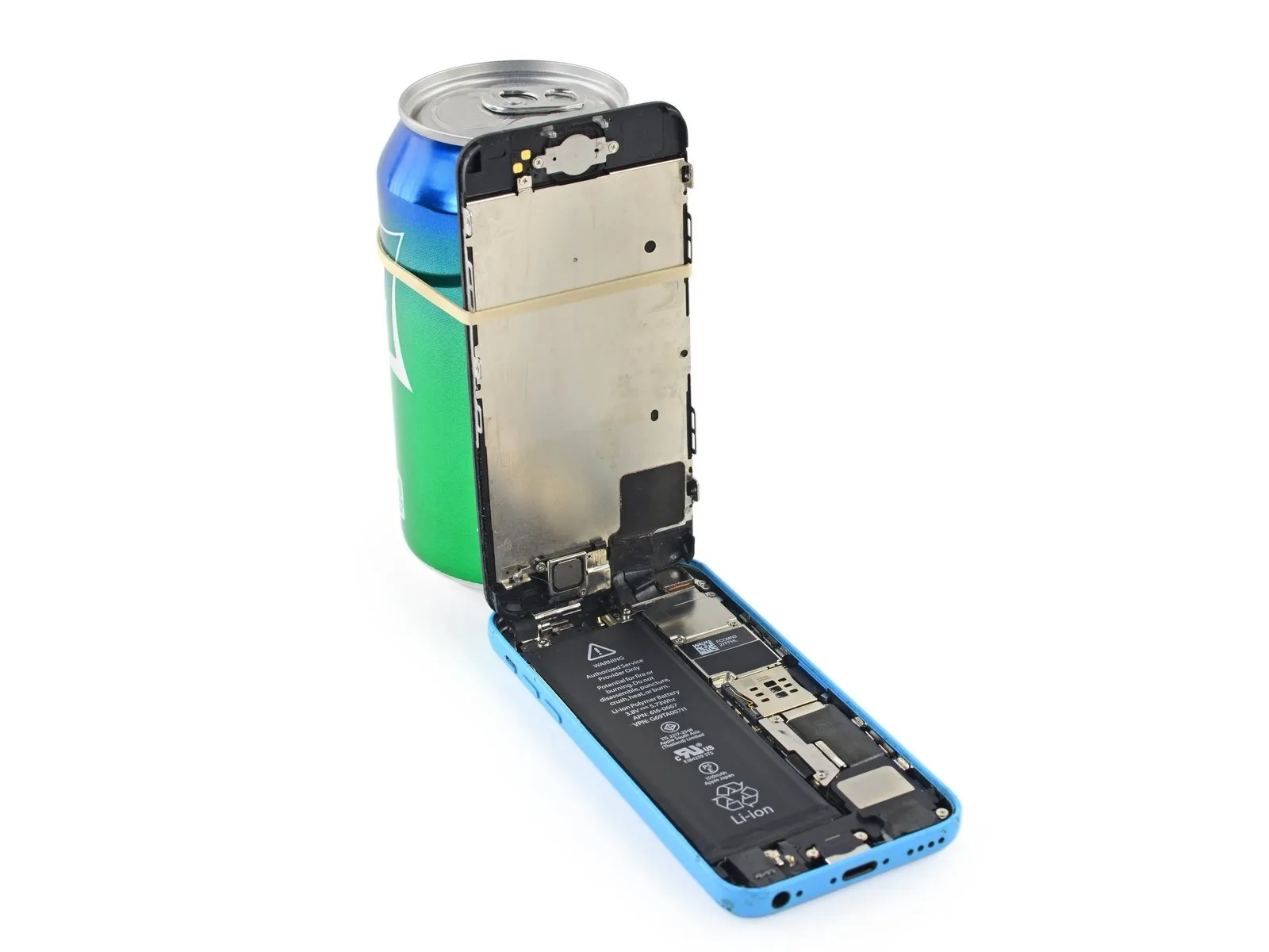
To expose the connectors located at the top edge of the device, carefully raise the front panel, beginning at the home button end.
Carefully position the display at a 90-degree angle, then secure it in an upright position using a support to allow for hands-free access during the repair process.
As a temporary measure, an unused, sealed can of soda can substitute for the display during the repair process.
To avoid stressing the display's wiring during the repair process, secure it with a rubber band.
Step 9
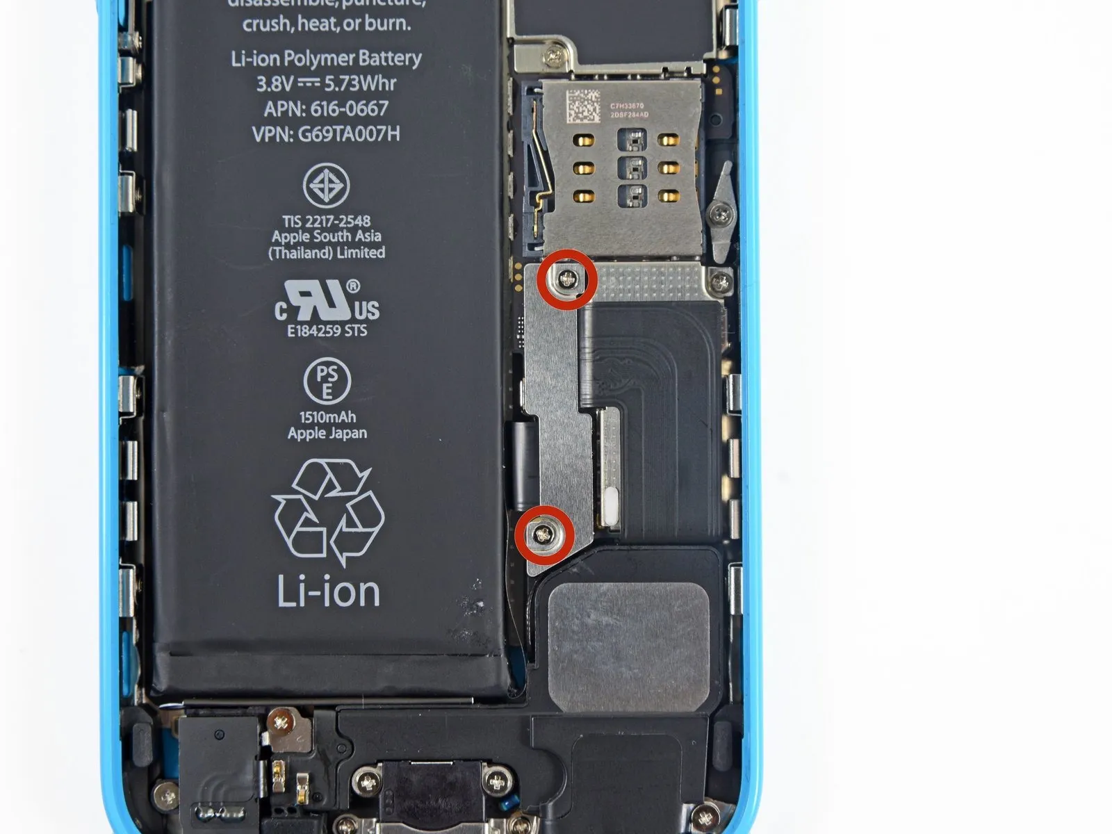
Using a Phillips #000 screwdriver, detach the metal bracket that holds the battery connector by unscrewing the two 1.6 mm screws holding it in place on the logic board.
Step 10

Detach the bracket securing the battery connector using a tri-point screwdriver, ensuring no damage occurs to surrounding components.
Step 11 | Disconnecting the battery connector

Carefully lift the battery connector away from its corresponding socket on the logic board, employing a spudger or a clean fingernail to avoid damage.
Exercise extreme caution when releasing the battery connector, focusing your lifting force solely on the connector; applying pressure to the logic board socket or the board itself risks socket destruction or damage to adjacent components.
Exercise extreme caution when releasing the battery connector, focusing your lifting force solely on the connector; applying pressure to the logic board socket or the board itself risks socket destruction or damage to adjacent components.
Step 12

Using a Phillips #000 screwdriver, detach the bracket that secures the front panel assembly cable from the logic board by unscrewing all of its fasteners.
Use two screws, each measuring 1.3 millimeters.
A screw with a 1.7-millimeter head diameter is required.
A screw with a 3.25 mm diameter is required.
Carefully manage all screws during this stage to ensure correct reassembly; improper screw selection, such as using a 3.25 mm screw instead of a 1.7 mm screw in the bottom right hole, will severely damage the logic board and prevent the device from powering on.
Avoid applying excessive force when tightening screws; if resistance is encountered during installation, verify that the correct screw size is being used and do not force the fastener.
Step 13
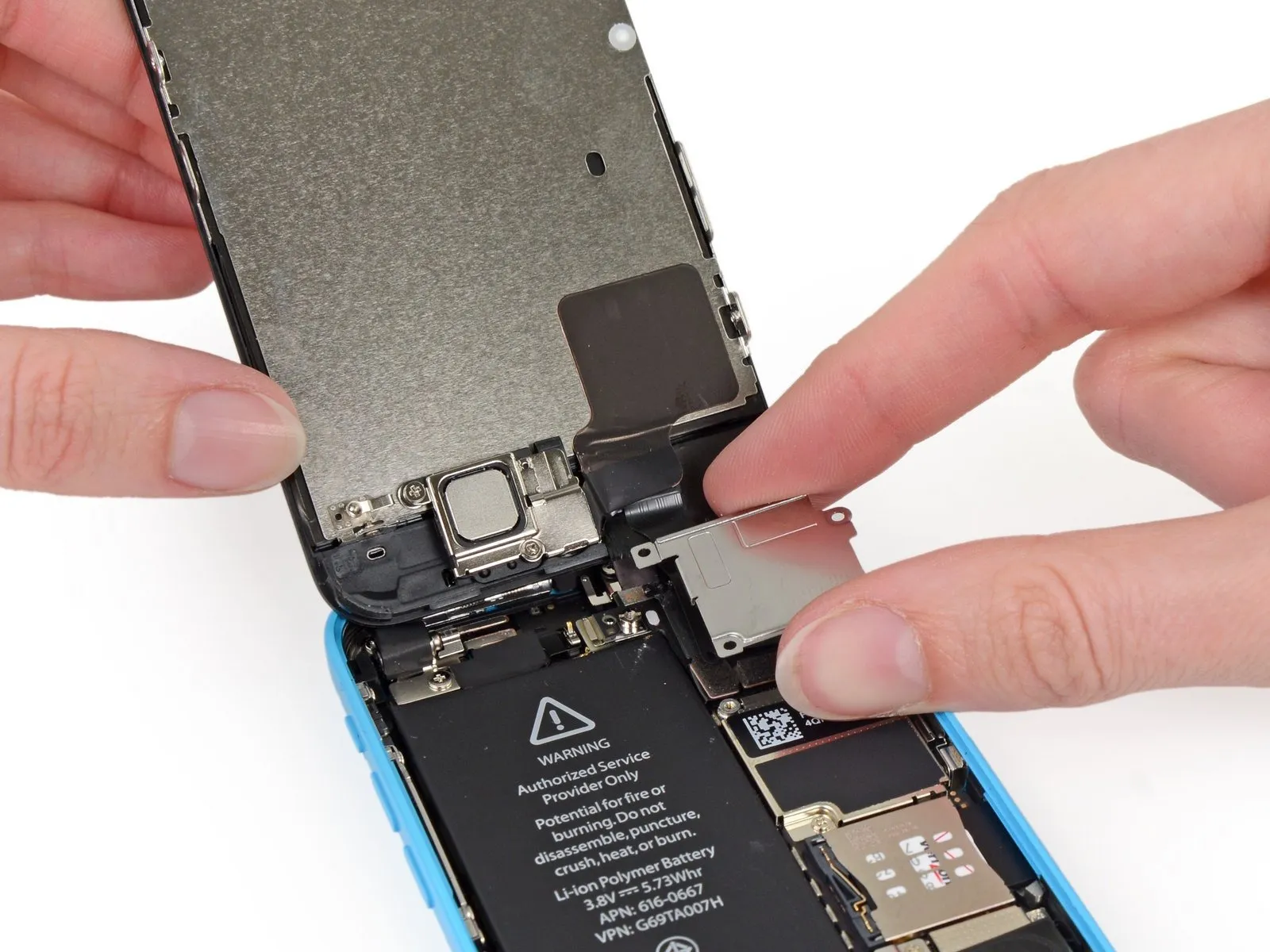
Detach the cable bracket securing the front panel assembly cable to the logic board.
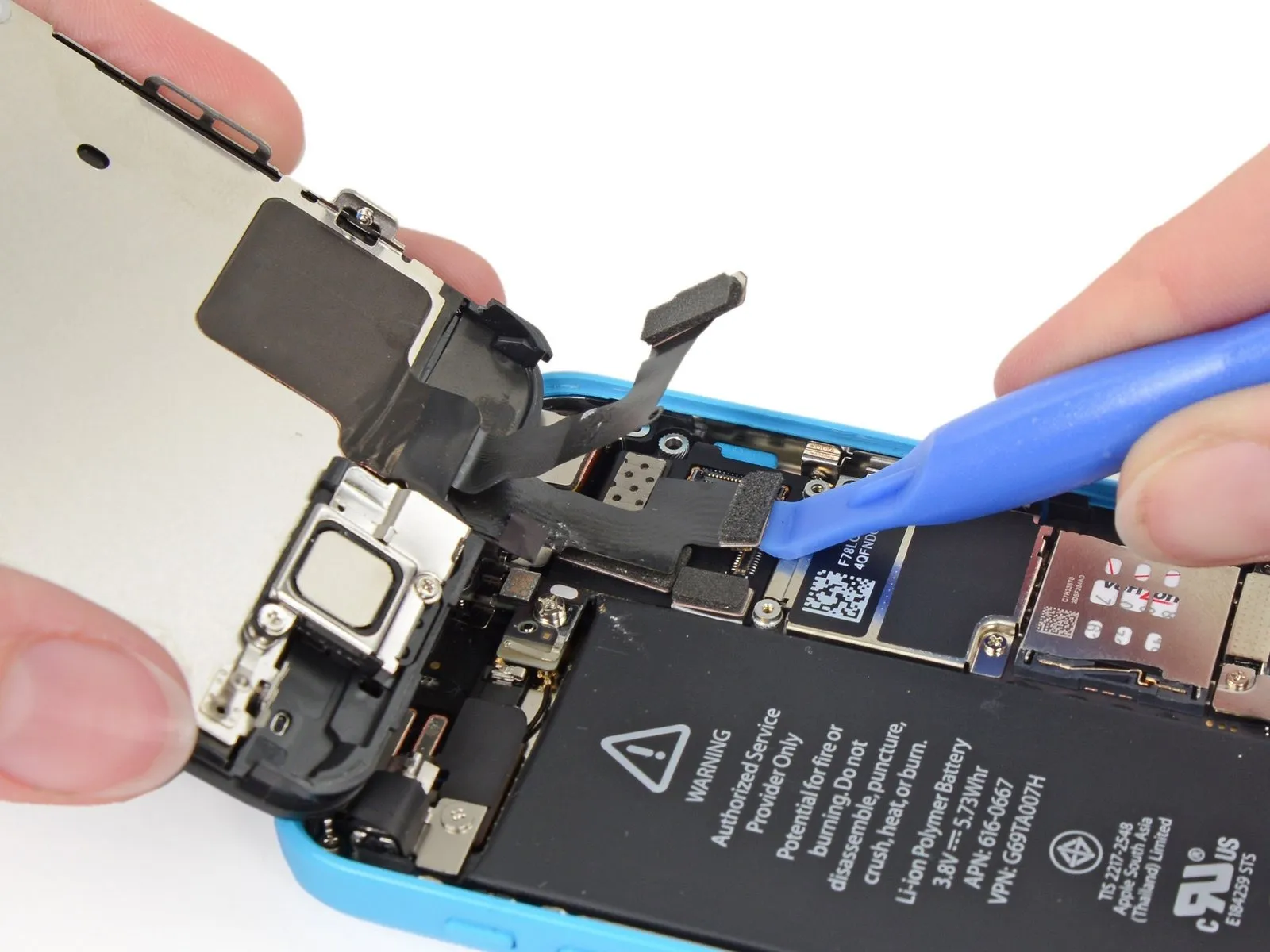
Step 14 | Disconnecting the front panel assembly cables

Carefully separate the front camera and sensor cable connector from its socket using a plastic pry tool or your fingernail.
Apply lifting force exclusively to the connector itself, avoiding any pressure on the socket secured to the logic board.
Apply lifting force exclusively to the connector itself, avoiding any pressure on the socket secured to the logic board.
Step 15

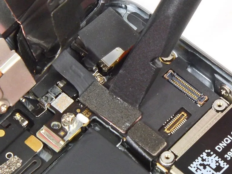
Prior to either detaching or reattaching the cables in this procedure, ensure the battery is disconnected.
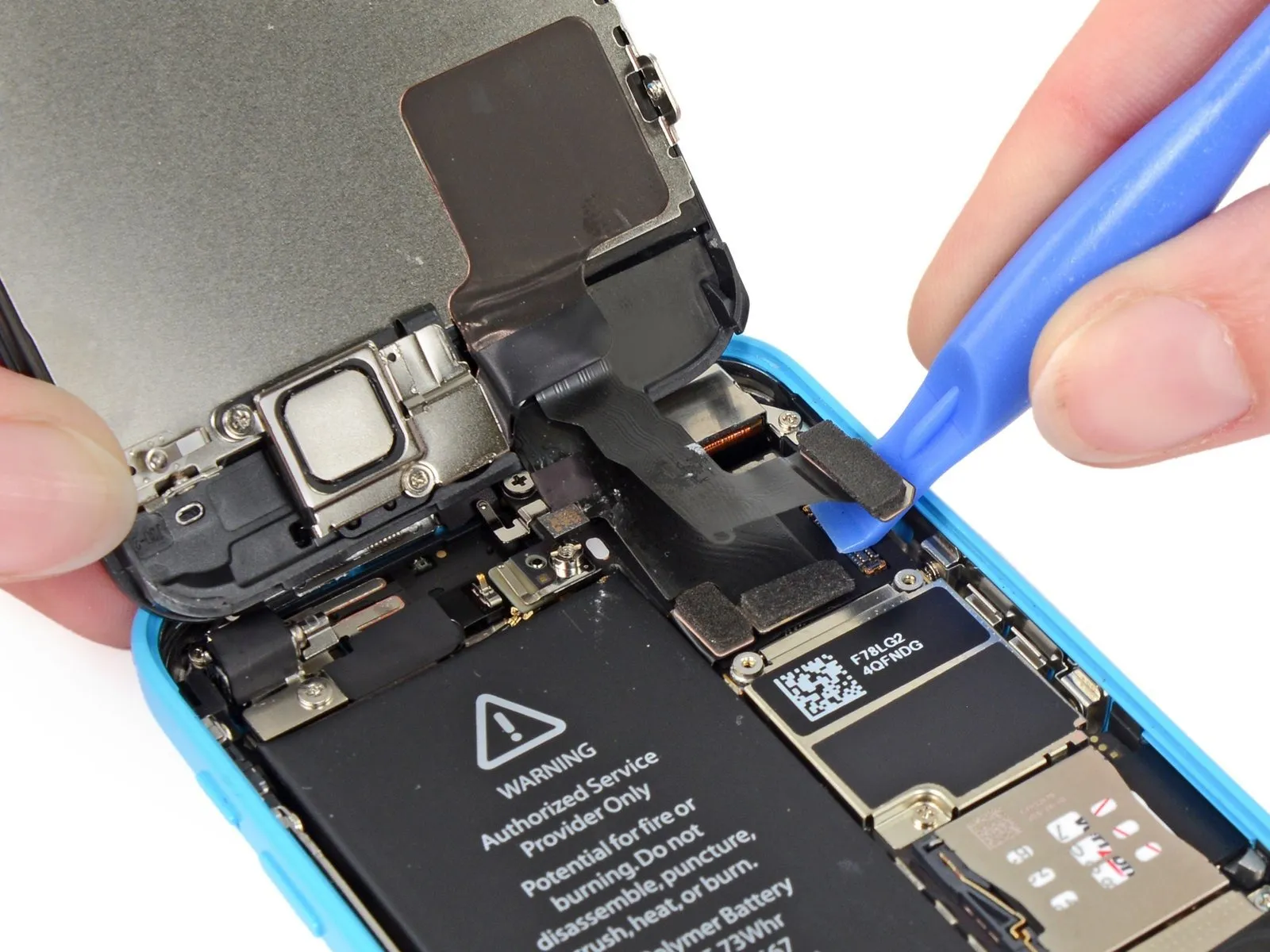
Carefully detach the LCD cable connector from its socket using a plastic pry tool or your fingernail.
Because the LCD and Digitizer share a single cable assembly, lifting the LCD connector will also release the Digitizer connector; ensure both cables are completely detached prior to display removal.
A disconnected LCD cable from its connector during reassembly can result in a blank screen or white lines; to resolve this, ensure the cable is securely attached and restart the device by briefly removing and reinstalling the battery.
Step 16 | Separating front panel assembly and rear case

Detach the front panel assembly from the rear case.
Step 17 | Battery


Using a spudger, carefully separate the battery from the headphone jack by releasing the adhesive tab.
Step 18

Carefully detach the battery's adhesive pull tab to release it from the device.
Step 19


Using a cutting tool, sever the black battery adhesive tab by slicing through the two white adhesive strips that hold it in place, thus detaching the tab.
Step 20


To prevent the strips from adhering and tearing, maintain their flatness and avoid creases throughout this step.
Gently peel back a battery adhesive tab, directing its movement downwards along the iPhone's interior.
To detach the strip, apply consistent, even force while guiding it out from the space between the battery and the rear case; ensure the pulling angle remains at 60 degrees or less to optimize the release.
Maneuver the adhesive strip along the battery's edge, ensuring it follows the corner and ascends the side, while avoiding contact with other internal iPhone parts to prevent damage.
To release the strip completely, maintain traction and extend it significantly beyond its initial size; reposition your grip closer to the battery as needed to facilitate the full detachment.
Step 21


Execute the preceding steps once more.
Carefully detach the second strip.
Carefully detach the second strip.
Step 22

Disconnecting the iPhone's battery is necessary for this repair; ensure you follow all safety precautions and use the appropriate tools to avoid damage.
Should the adhesive strips break or become inaccessible with tweezers, refrain from attempting to dislodge the battery using force; proceed directly to the subsequent instructions for safe battery removal.
Should the adhesive strips break or become inaccessible with tweezers, refrain from attempting to dislodge the battery using force; proceed directly to the subsequent instructions for safe battery removal.
Step 23 | Battery removal with latent adhesive


To loosen the adhesive securing the battery, carefully introduce a small amount of isopropyl alcohol with a concentration of 90% or higher beneath the battery, allowing it to spread; this high-concentration alcohol functions as a solvent and evaporates completely, posing no risk to your iPhone.
Using a plastic card, gently insert the edge beneath the battery, positioning it closest to the logic board.
Applying force to the logic board can result in device damage.
Exercise caution and do not insert tools near the battery's upper edge to prevent potential damage to the ribbon cable connecting the upper component.
Using a card, move it along the battery's top edge, directing it downwards towards the case's perimeter to release the battery.
Should the need arise, perform the identical steps again on the battery's exterior casing.
Step 24

To release a battery adhered to the device housing, apply heat using the iOpener tool as detailed in our instructions, or alternatively, use a hair dryer to soften the adhesive bond between the battery and the rear case.
Position the iOpener horizontally against the iPhone’s rear casing, directly adjacent to the camera module, ensuring full surface contact between the device’s back panel and the iOpener.
Allow the desiccant bag to remain in contact with the iPhone for roughly 90 seconds prior to battery removal.
Apply warmth to the rear casing of the iPhone with a hair dryer or heat gun, ensuring the surface reaches a temperature just beyond comfortable touch.
Avoid direct application of heat to the battery.
Exposure to excessive heat presents a risk of battery ignition within the iPhone.
Step 25

Carefully detach and extract the iPhone's battery.
To prevent damage, ensure any residual alcohol solution is either thoroughly wiped away or completely evaporated from the device prior to battery installation.
Confirm the connection is free of any obstruction; if the battery is still adhered, apply more heat with the iOpener and repeat the separation process.
Carefully discard the protective plastic packaging that accompanied the new battery by gently separating it from the ribbon cable.
To guarantee correct positioning within its designated space, briefly reattach the battery connector to the motherboard socket prior to securing the new battery.
Secure the battery in place, then sever its electrical connection before proceeding with the remaining assembly steps.
To secure a battery lacking factory-applied adhesive, follow the instructions in this guide for adhesive strip replacement.
Following reassembly, execute a complete system reset to mitigate potential problems and streamline any subsequent diagnostic procedures.