iPhone 4S Logic Board Replacement
Follow these instructions to substitute a new logic board into your iPhone.
Step 1 | Rear Panel

To prevent electrical shock or damage, ensure the iPhone is completely de-energized prior to starting the repair process.
Using a Pentalobe P2 screwdriver, detach the two screws measuring 3.6 mm located adjacent to the dock connector.
To prevent damage, ensure the driver is fully engaged with the Pentalobe screws before turning, as they are prone to stripping.
Step 2


Expect a displacement of approximately 2 millimeters.
Step 3
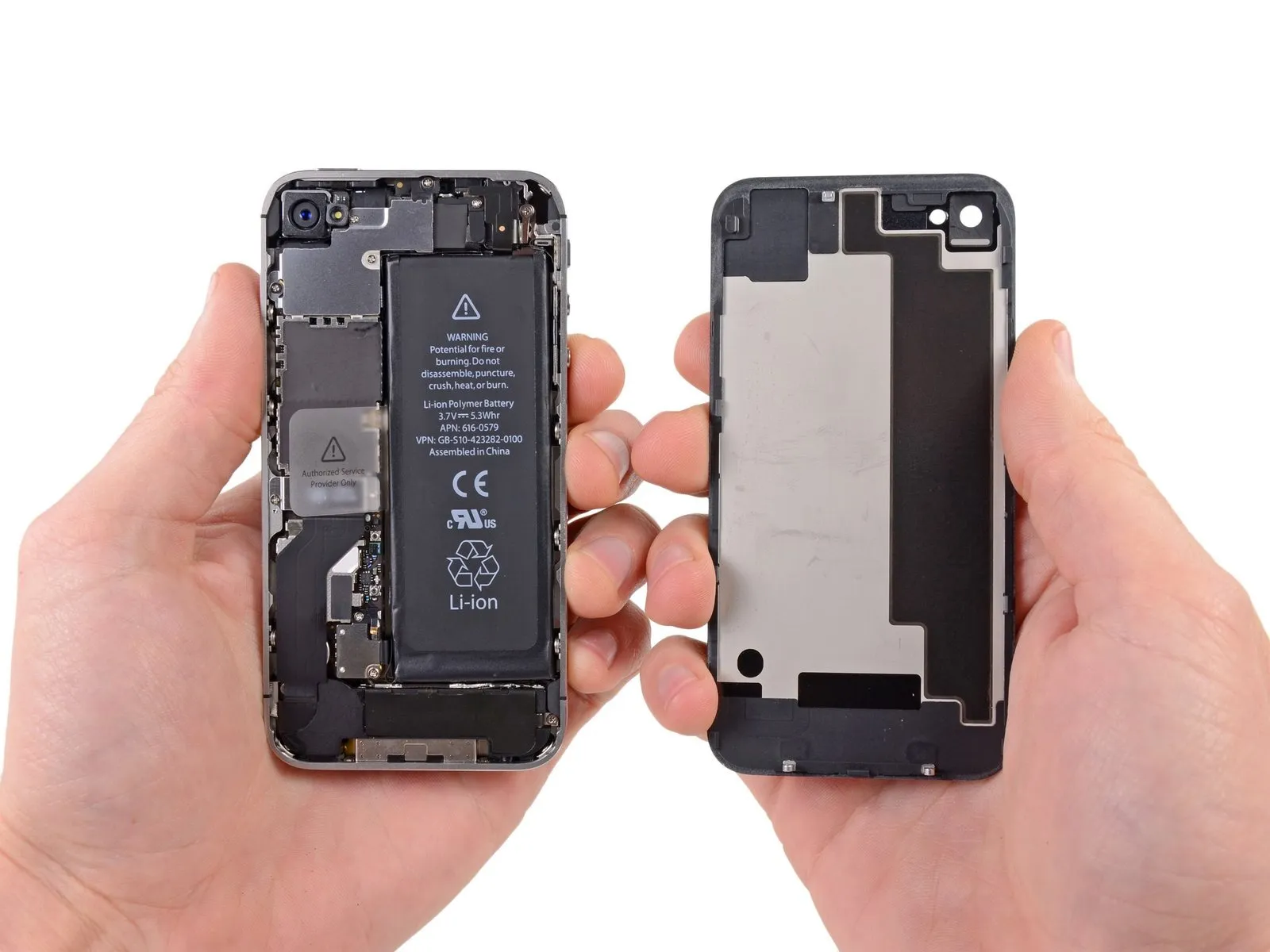
Carefully detach the iPhone’s back cover.
Step 4 | Battery
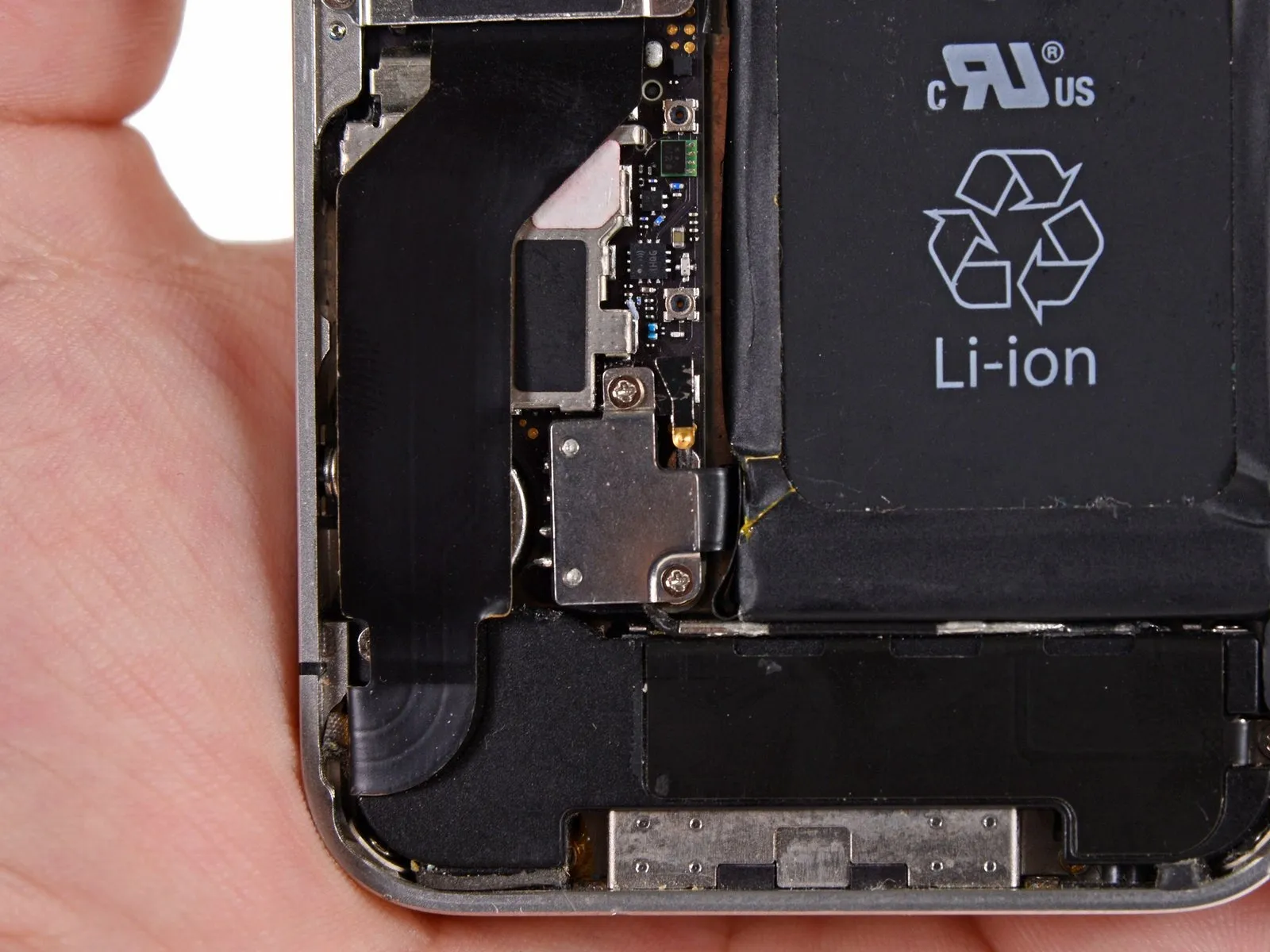
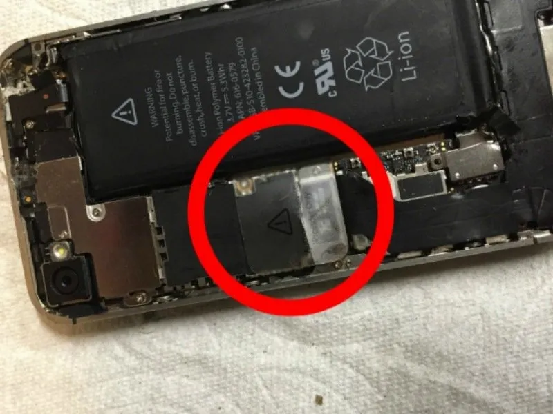
Employ a PH00 Phillips screwdriver to loosen and remove a 1.7-millimeter screw.
Utilize a PH00 Phillips screwdriver to remove a 1.5 mm screw.
Step 5
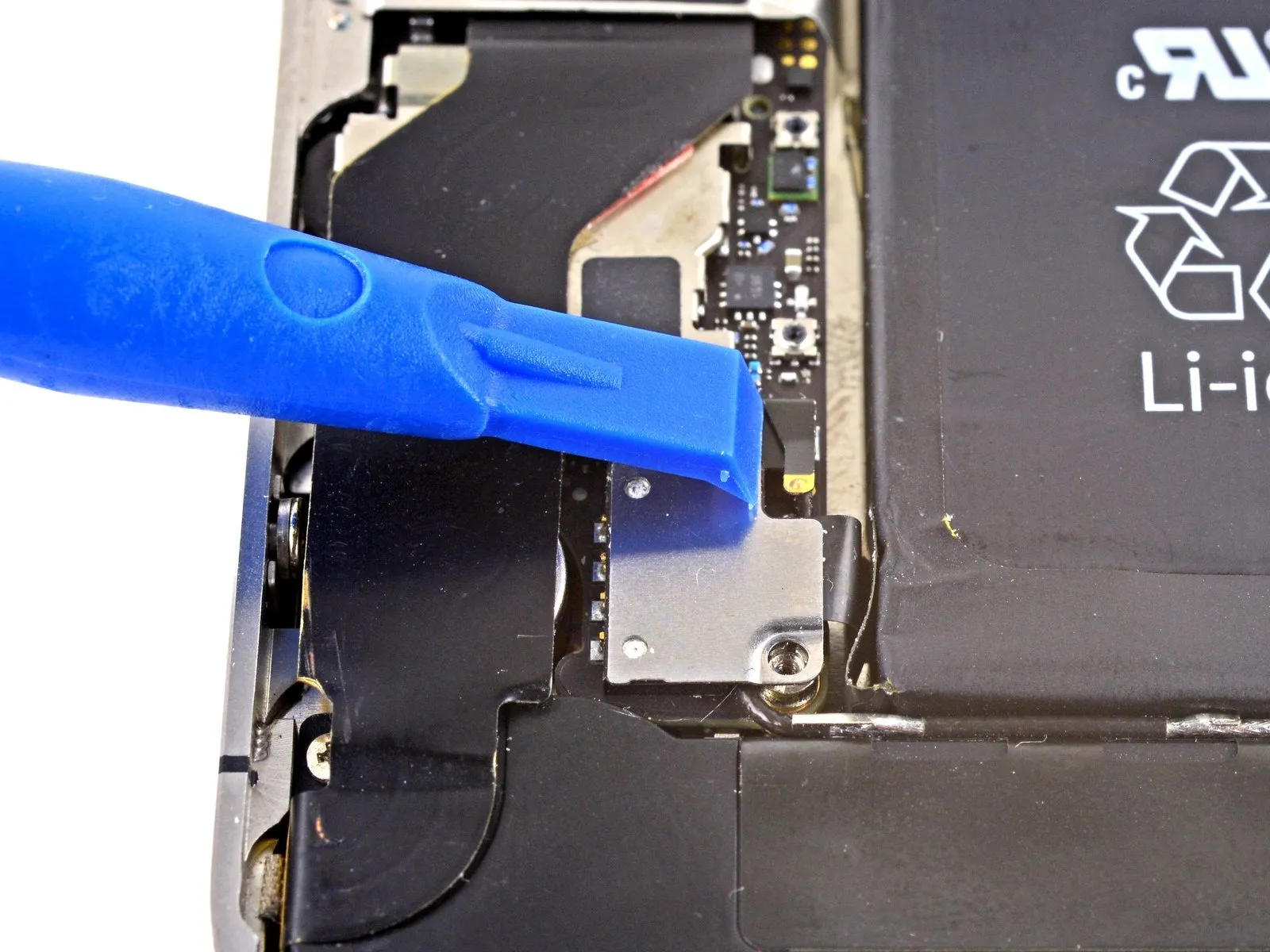
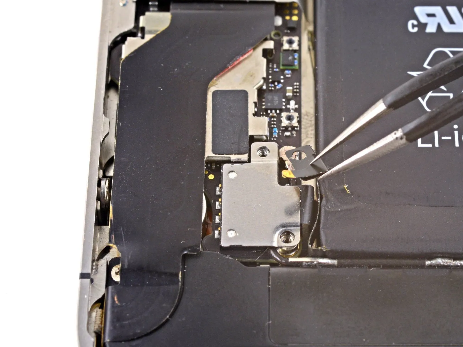
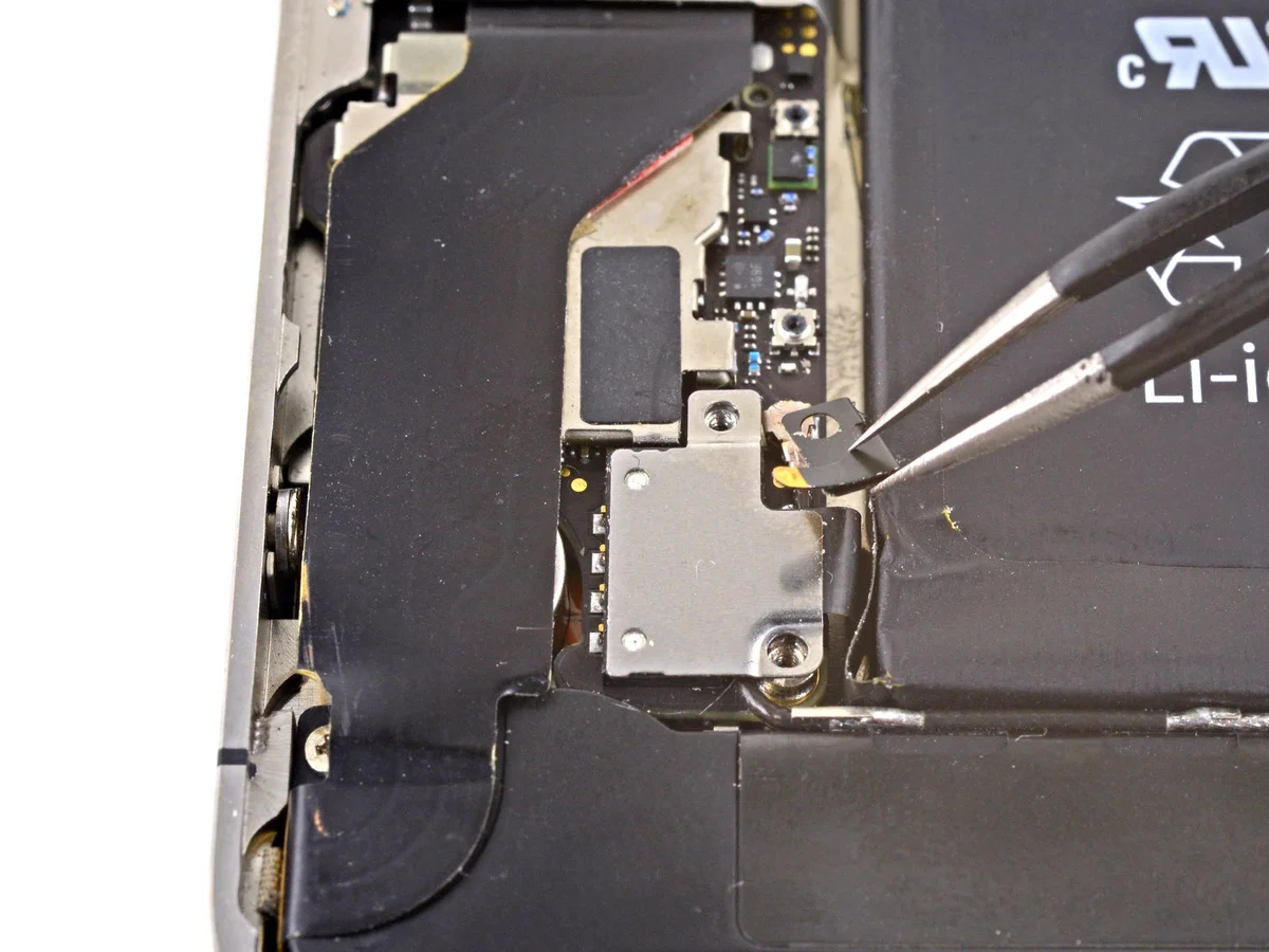
Disconnect the pressure contact.
Step 6
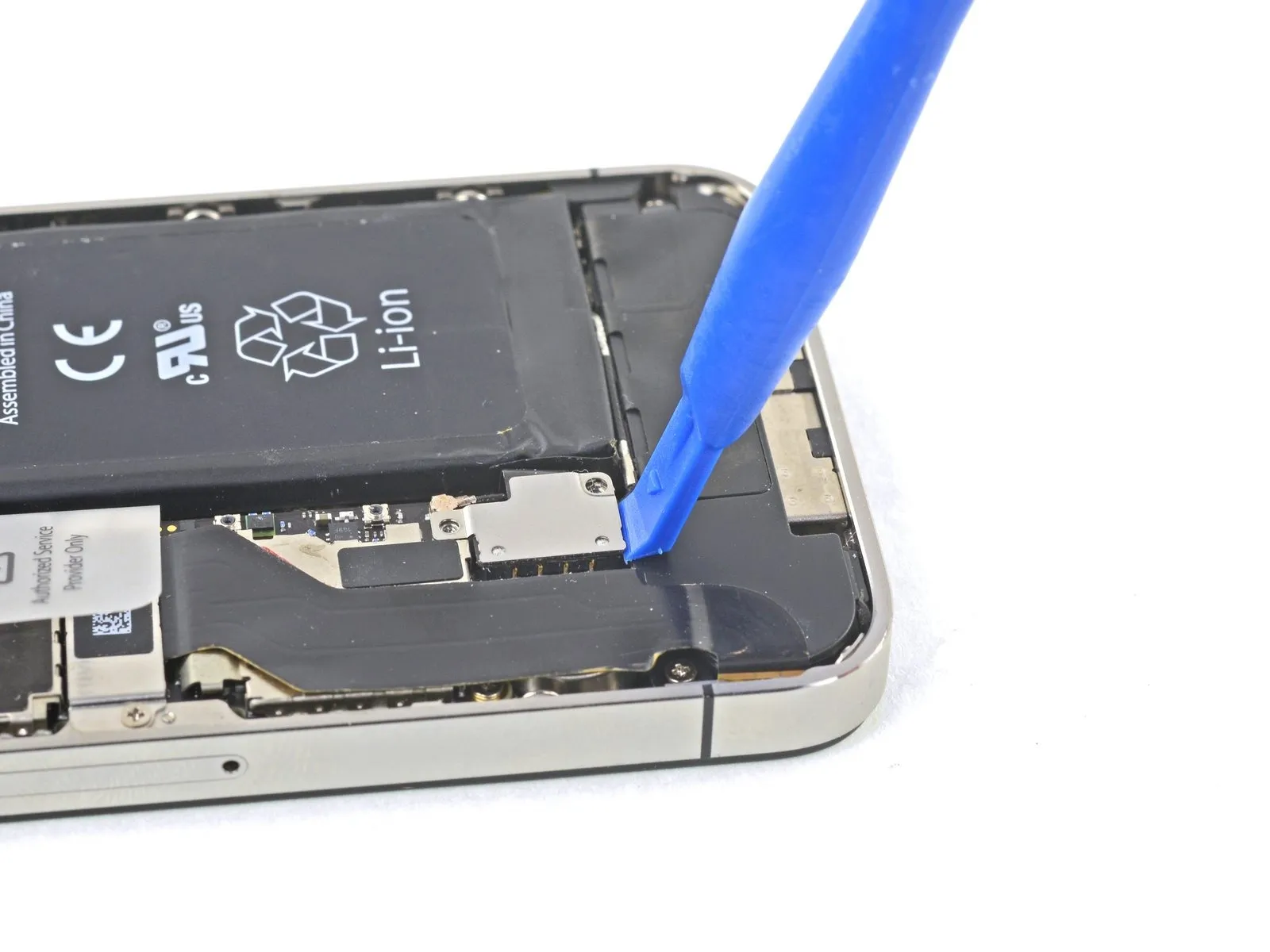
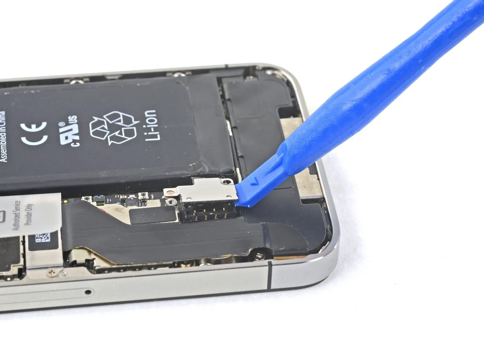
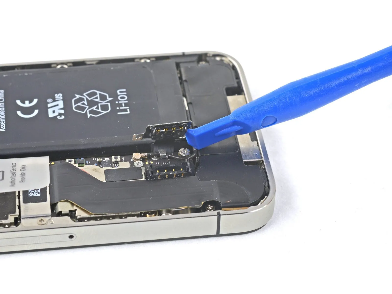
- Carefully disconnect the battery connector from its corresponding socket on the logic board by leveraging a plastic opening tool.
Using the tool, gently separate the connector's metal cover from the loudspeaker enclosure by inserting the tip between them and raising the connector's lower edge.
To detach the battery connector, move it straight up away from the logic board; avoid lateral pressure.
Avoid applying force directly to the battery connector's socket, as this could dislodge it from the logic board due to the presence of four delicate solder joints.
Step 7 | Reassembly tip
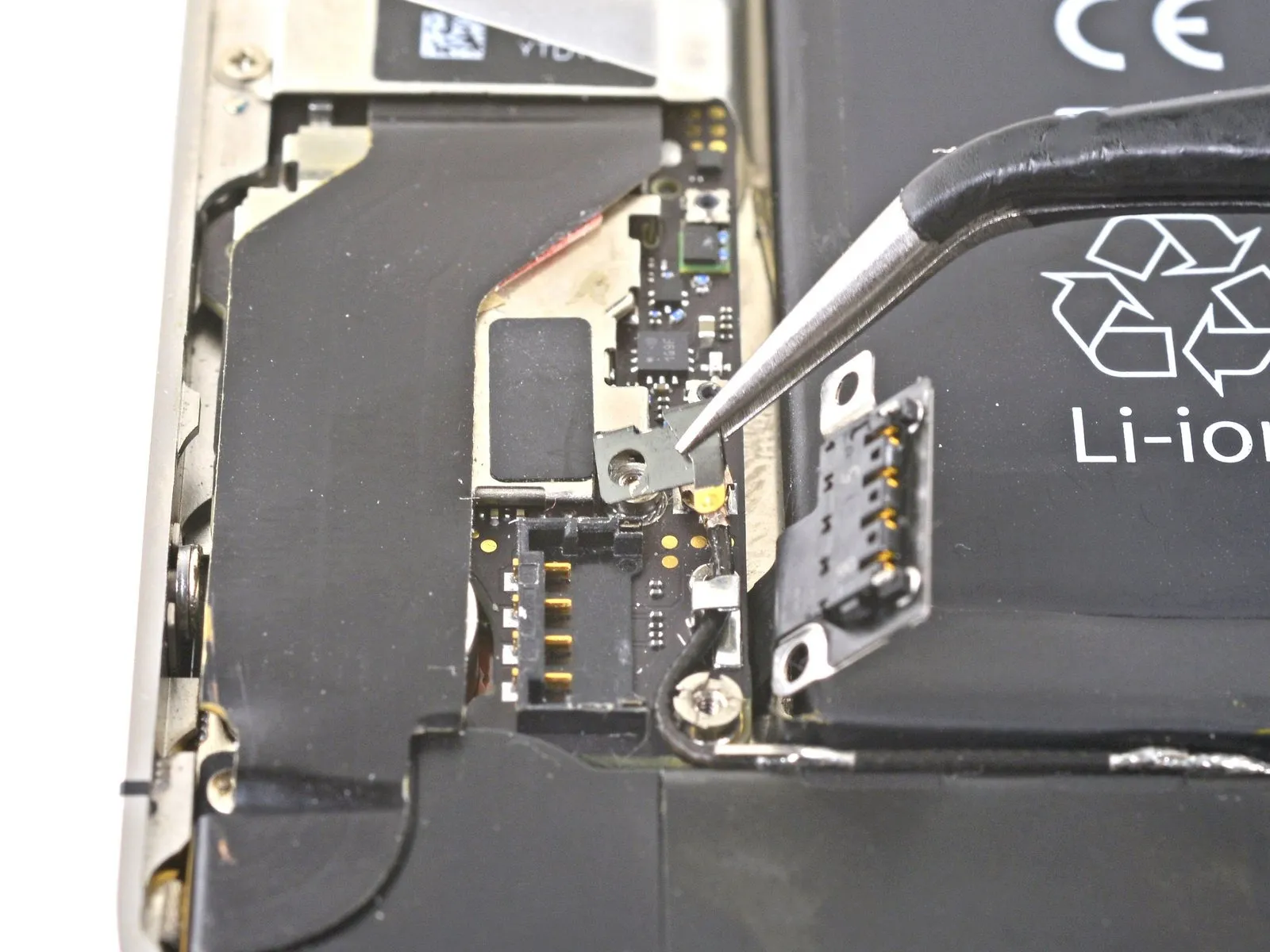
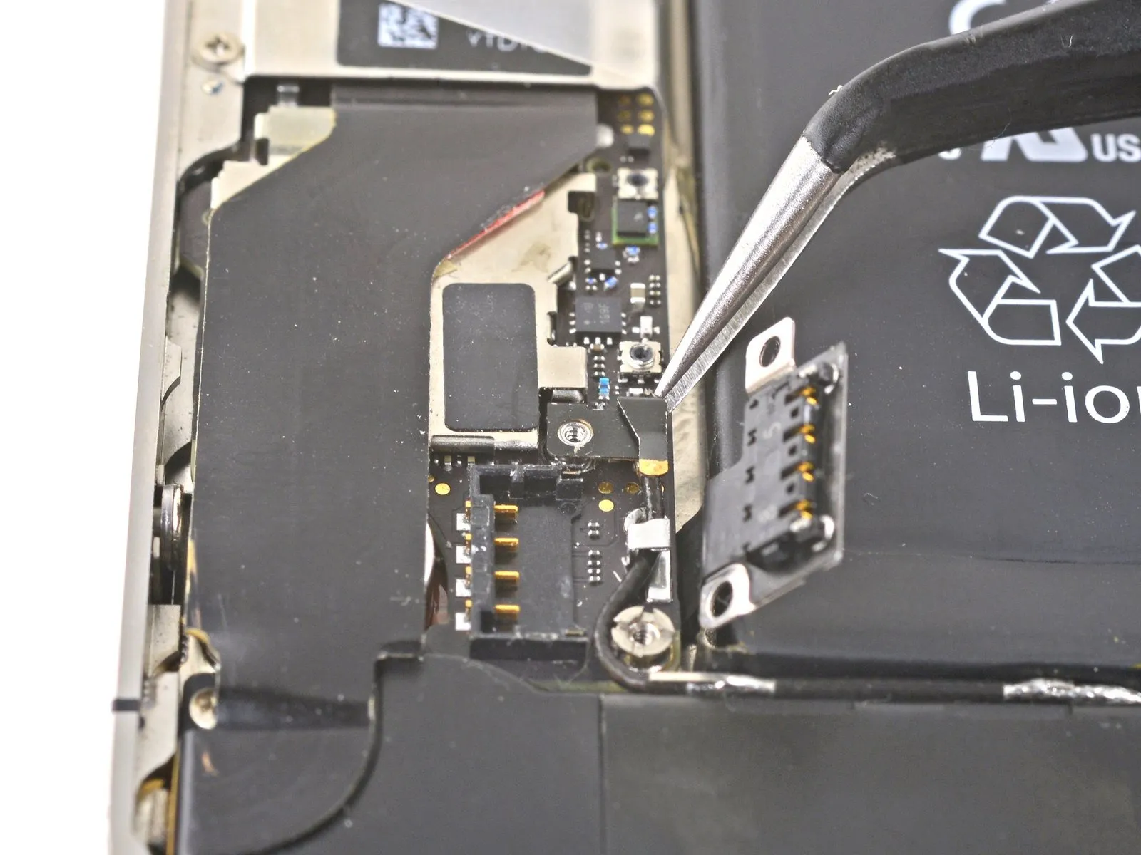
Ensure the pressure contact is correctly aligned during reassembly, placing it so it sits atop the designated Philips screw post and its gold contact faces the battery connector.
To prevent wireless interference caused by oils from handling, thoroughly wipe the pressure contact using a cleaning agent like Windex or isopropyl alcohol.
Step 8
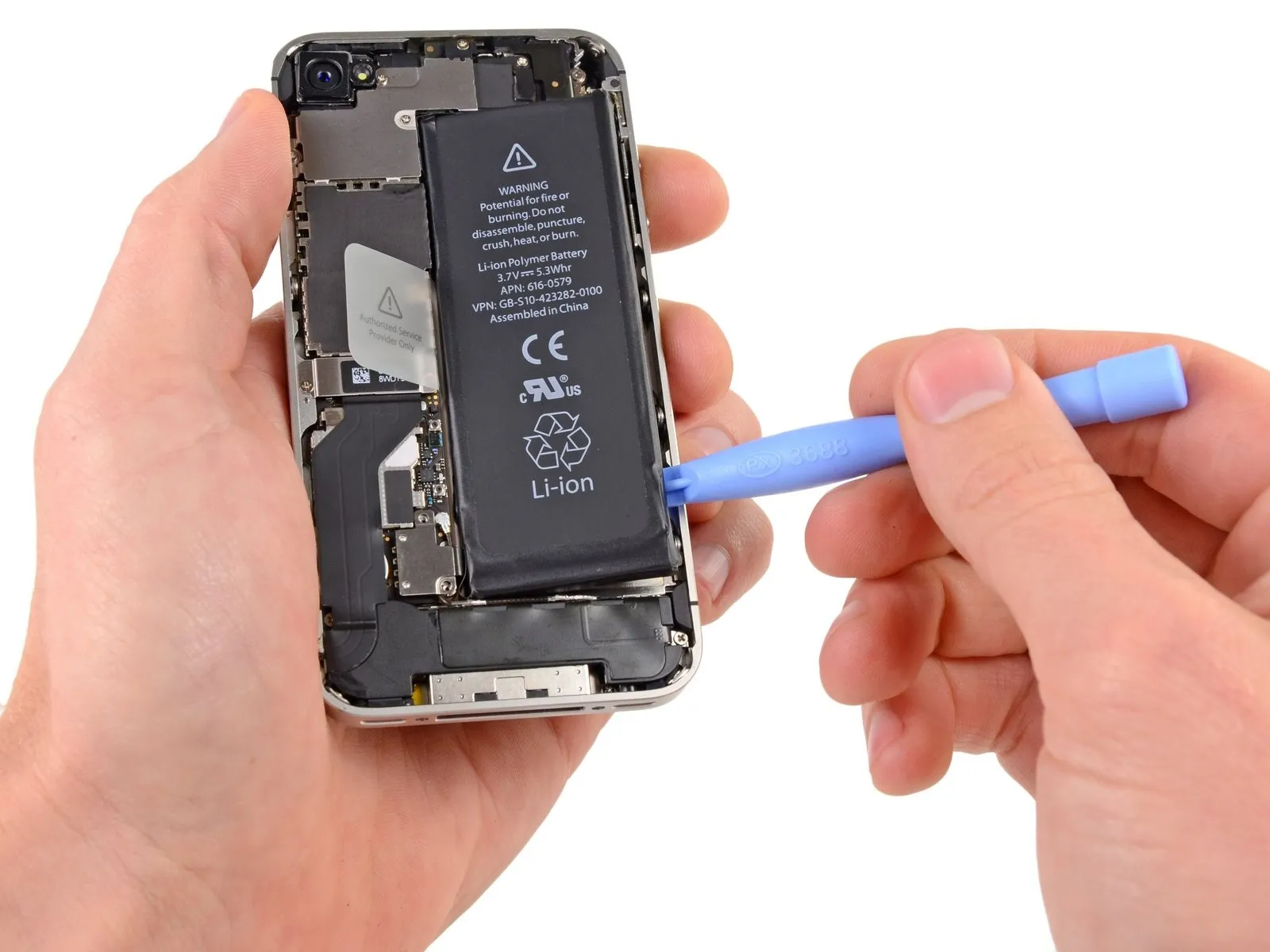
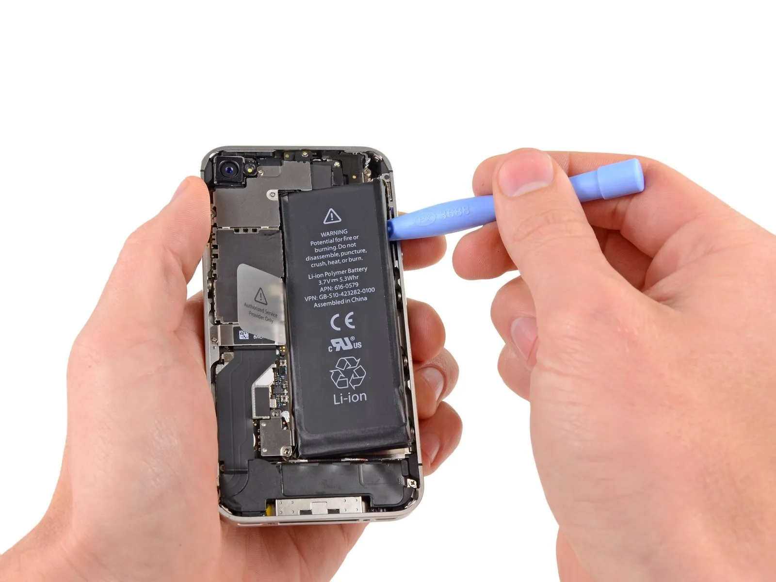
- Using a plastic opening tool, gently slide the tip into the gap separating the battery from the iPhone’s outer casing, positioning the tool close to the device's lower edge.
Using the plastic opening tool, carefully work along the right side of the battery, lifting gently at multiple locations to release the adhesive that holds it in place within the outer case, ensuring complete separation.
To loosen a firmly adhered battery, carefully introduce a small amount of isopropyl alcohol with a concentration exceeding 90% beneath its perimeter.
Allow approximately sixty seconds for the isopropyl alcohol to reduce the bonding strength of the adhesive.
Carefully raise the battery using the flat, plastic tip of a specialized opening tool.
To avoid damage, do not use excessive force when removing the battery. If the battery remains stuck, add additional alcohol to dissolve the adhesive; ensure the pry tool does not bend, break, or penetrate the battery casing during removal.
To prevent damage, ensure any residual alcohol solution is completely removed by wiping with a clean cloth or by permitting it to evaporate fully prior to battery replacement.
Step 9


Gently lift the battery from its adhesive backing by grasping the visible, transparent plastic tab.
Exercise caution when drawing back the plastic tab, as excessive force may cause it to tear.
Disconnect the power source by extracting the battery.
Carefully detach the protective plastic packaging from the new battery by gently separating it from the ribbon cable.
Before phone reassembly, ensure the new battery's cable is formed into the correct contour.
To verify correct positioning during the new battery installation, briefly attach the battery connector to the device; after securing the battery with adhesive, detach the connector.
Following reassembly, execute a factory reset to mitigate potential problems and streamline any subsequent diagnostic procedures.
Step 10 | Dock Connector Cable


Using appropriate tools, detach the dock connector cable cover from the logic board by unscrewing all screws that hold it in place.
Use a Phillips screwdriver to tighten a single screw with a 1.5 mm head.
Use a Phillips screwdriver to tighten a 1.2-millimeter screw.
Carefully detach the metal cover protecting the dock connector cable.
Step 11

Step 12

Step 13


Carefully maneuver the cellular antenna cable, freeing it from the metal finger retainers secured to the logic board.
Step 14 | Rear Camera

Employing tweezers, a plastic pry tool, or a spudger, carefully detach the surrounding plastic ring.
Step 15

Employ a Phillips screwdriver, sized specifically for 2.7 mm fasteners.
Employ a Phillips screwdriver, sized for a 2.6 mm head.
Employ a Phillips screwdriver with a 1.3-millimeter bit.
Employ a Phillips head screwdriver, sized 1.2 millimeters.
Step 16


Carefully detach the cable cover by gently prying upwards from the side closest to the uppermost edge, then separate it from the iPhone.
Step 17


Exercise caution to avoid damaging adjacent parts while lifting.
Carefully detach the iPhone’s rear camera assembly.
Before reassembling, confirm the tiny rubber gasket positioned beneath the rear camera is correctly aligned.
Step 18 | SIM Card


Applying considerable pressure might be necessary.
Using the SIM tray removal tool, or a straightened paperclip, carefully eject the SIM card tray and extract the SIM card.
Step 19 | Logic Board


- The flexible cable connecting the headphone jack and volume controls must be handled with care.
- Connect the front camera’s ribbon cable.
- The flexible ribbon cable connecting the display's touch sensor to the mainboard is the digitizer cable.
- Connect the display data cable.
- Refer to the second image to identify the power button cable; it's situated directly below the headphone jack/volume button cable.
Carefully leverage the connectors of the cables upward and away from the logic board’s sockets using a plastic opening tool to avoid damage.
Exercise caution to avoid damaging the tiny, sensitive surface mount components while disconnecting the cables.
Step 20

Step 21


Detach the iPhone from the grounding clip by holding it firmly.
To prevent grounding problems, thoroughly remove any residue from metal-to-metal contact areas on the grounding clip—excluding the connector housings—using a cleaning agent like Windex or isopropyl alcohol; this step is necessary because oils from handling can interfere with proper grounding.
Step 22

To detach standoff screws, utilize a standoff screwdriver or a compatible bit.
If a dedicated tool isn't available, a small flathead screwdriver can be carefully substituted; however, exercise heightened awareness to prevent slippage and potential harm to nearby parts.
Step 23

Step 24


Using a Phillips screwdriver, detach the logic board by removing the 2.6 mm screw located close to the power button.
Exercise care while loosening the screw, as it secures the power contact, which is prone to detachment during removal.
The tiny rubber bumper situated beneath the screen and digitizer cables—those disconnected above the Q-code—is prone to detachment; it may dislodge from the logic board during removal or become adhered to the cables and subsequently fall off.
Step 25

A Phillips screwdriver, size 2.5 mm, is needed to remove the screw located close to the vibrator motor.
Use a Phillips screwdriver to remove a screw with a 2.4 mm head.
Locate a 3.6 mm standoff positioned on the logic board's edge, closest to where the battery is situated.
Employ a standoff driver bit, attached to a driver handle, to detach the 3.6 mm standoff screw.
If a dedicated tool isn't available, a small flathead screwdriver can be carefully employed; however, exercise heightened vigilance to prevent slippage and potential harm to nearby parts.
Step 26

- Gently raise the logic board, starting at the speaker enclosure end, and move it horizontally, separating it from the iPhone's top edge.
Carefully detach the logic board, ensuring all connections are fully disengaged. - To prevent grounding problems, thoroughly remove any oils transferred from handling by cleaning all metal surfaces that will touch other metal components on the logic board—excluding connector pins—using a solvent like Windex or isopropyl alcohol before reassembling.
- A tiny rubber bumper, positioned along the logic board's upper edge at the point where the digitizer and screen cables exit the case, safeguards those cables from damage caused by bending. This component may adhere to the cables or detach from the logic board during disassembly; refer to step 22 for additional information.
Step 27

The tiny grounding finger, essential for the rear camera's functionality, is located close to the power button; secure it by ensuring it remains positioned atop the printed circuit board and is fastened with screws, all while being protected by the black adhesive plastic tape.