iPhone 4 Vibrator Replacement
This guide details the procedure for substituting the vibrator motor, which generates the vibration alerts for incoming calls.
Step 1 | Rear Panel
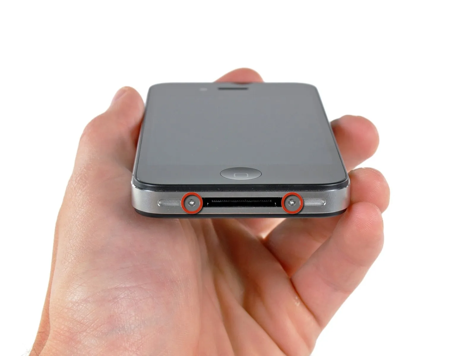

To start, ensure the iPhone's battery has depleted to a level below 25% capacity; a fully charged lithium-ion battery presents a fire and/or explosion hazard if damaged.
To prevent electrical shock or damage to components, ensure the iPhone is completely de-energized prior to starting the repair process.
The iPhone 4's back cover is secured with either two #000 Phillips head screws or Apple's proprietary 5-Point "Pentalobe" screws, as shown in the second image. Verify the screw type present and use the corresponding screwdriver to successfully remove them.
Using either a Pentalobe or Phillips #000 screwdriver, detach the two screws measuring 3.6 mm located adjacent to the dock connector.
To prevent damage, ensure the Pentalobe driver is fully engaged before unscrewing, as these screws are prone to stripping.
To prevent electrical shock or damage to components, ensure the iPhone is completely de-energized prior to starting the repair process.
The iPhone 4's back cover is secured with either two #000 Phillips head screws or Apple's proprietary 5-Point "Pentalobe" screws, as shown in the second image. Verify the screw type present and use the corresponding screwdriver to successfully remove them.
Using either a Pentalobe or Phillips #000 screwdriver, detach the two screws measuring 3.6 mm located adjacent to the dock connector.
To prevent damage, ensure the Pentalobe driver is fully engaged before unscrewing, as these screws are prone to stripping.
Step 2
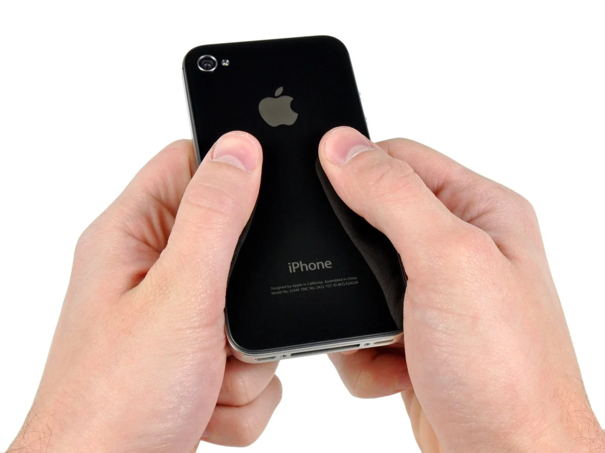
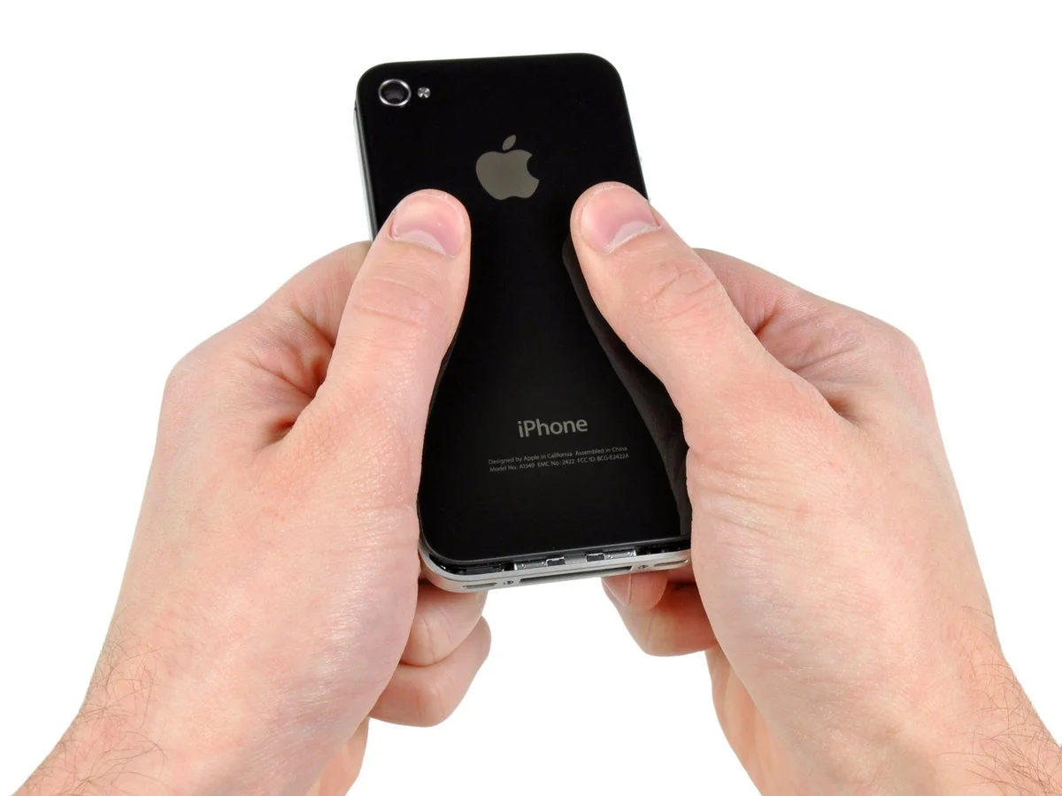
Apply pressure to the back cover, directing it upwards against the device's upper rim.
Expect a displacement of approximately 2 millimeters.
Expect a displacement of approximately 2 millimeters.
Step 3
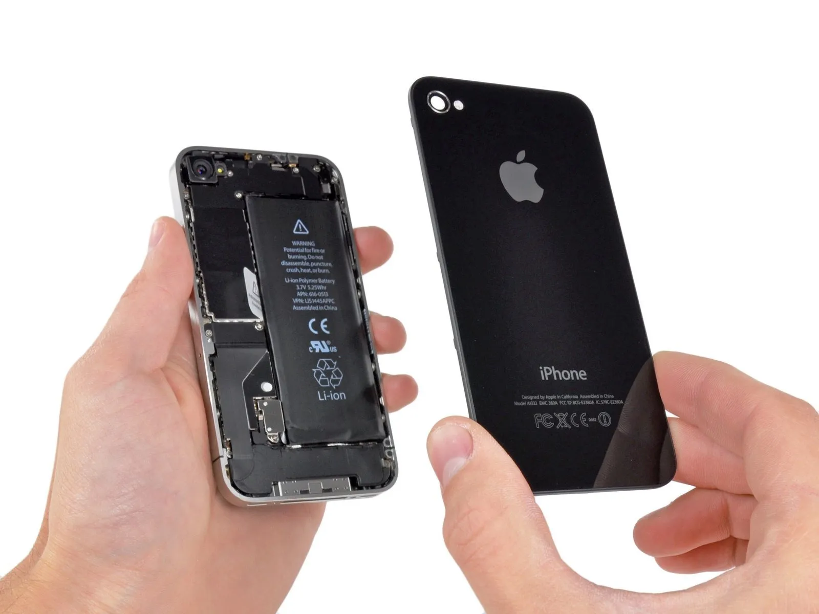
To detach the rear panel, either gently raise it by applying pressure with your fingers or secure a Small Suction Cup to the panel and lift.
Exercise caution to prevent harm to the plastic clips affixed to the rear panel.
Before attaching a replacement rear panel, peel away the adhesive backing from the protective plastic covering the camera lens's interior surface, and also remove the sticker adhered to the large black area positioned close to the lens.
Exercise caution to prevent harm to the plastic clips affixed to the rear panel.
Before attaching a replacement rear panel, peel away the adhesive backing from the protective plastic covering the camera lens's interior surface, and also remove the sticker adhered to the large black area positioned close to the lens.
Step 4 | Battery
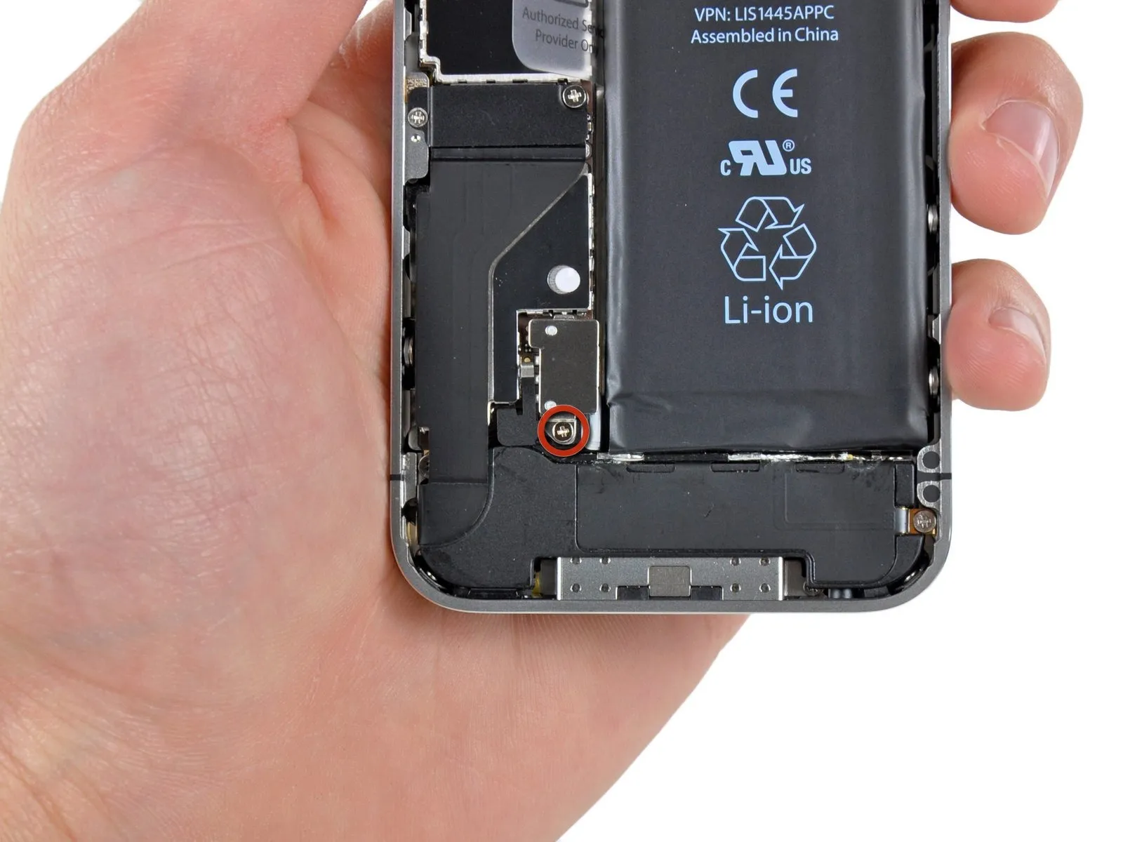
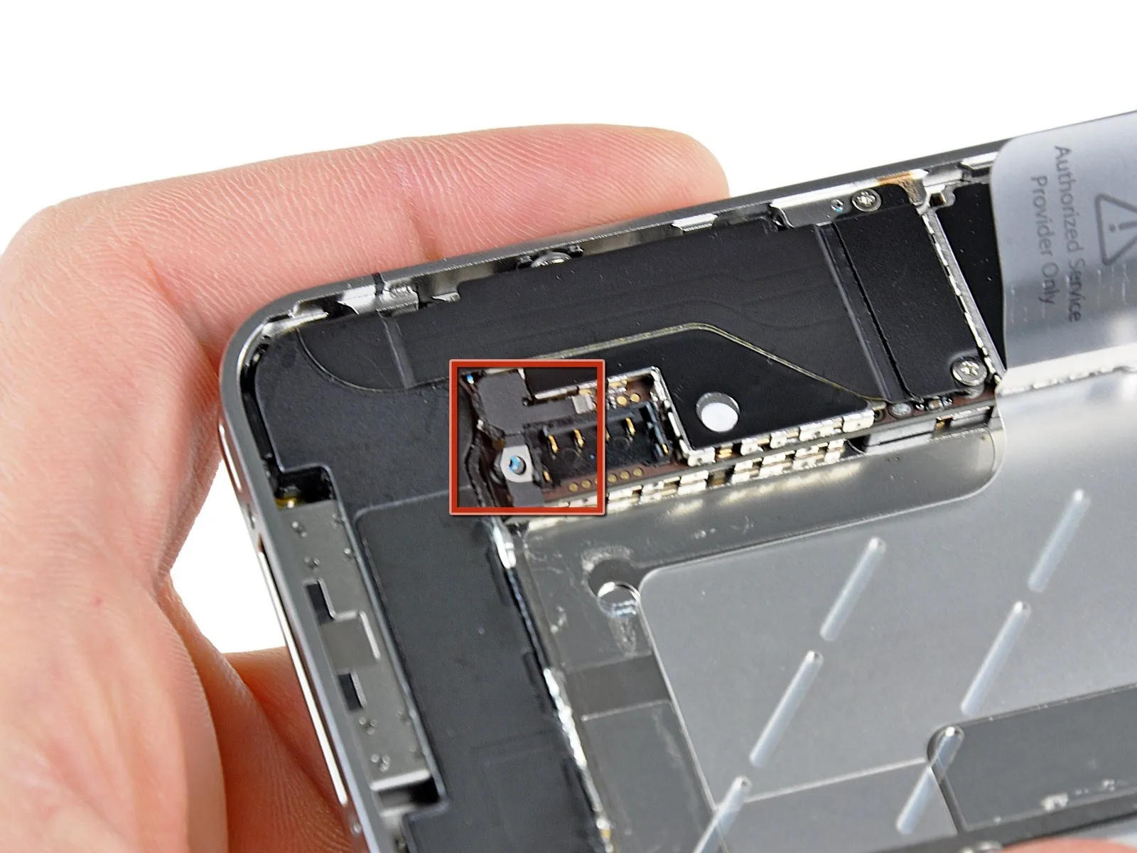
Using a Phillips screwdriver, detach the battery connector from the logic board by unscrewing the single 2.5 mm screw that holds it in place.
Depending on the model, a second screw secures the contact pad positioned directly above the screw highlighted in red within the provided image.
Depending on the model, a second screw secures the contact pad positioned directly above the screw highlighted in red within the provided image.
Step 5
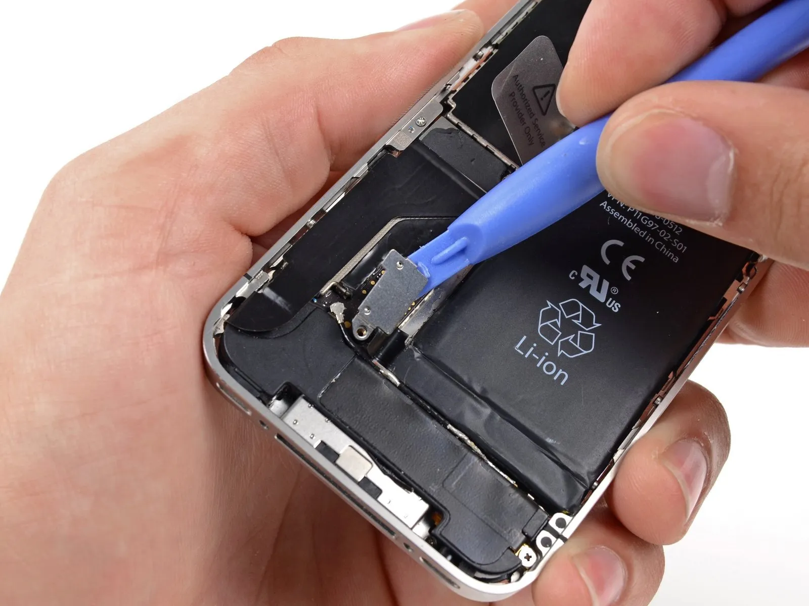
Carefully lift the battery connector away from its connection on the logic board using a plastic opening tool, ensuring no force is applied.
To avoid connector damage, apply releasing force to the upper and lower portions of the bracket, as side access is limited.
Exercise extreme caution when releasing the battery connector, ensuring you apply force only to the connector itself, as applying pressure to the logic board socket risks irreparable damage.
Carefully detach the metal clip, which secures the antenna connector.
To avoid connector damage, apply releasing force to the upper and lower portions of the bracket, as side access is limited.
Exercise extreme caution when releasing the battery connector, ensuring you apply force only to the connector itself, as applying pressure to the logic board socket risks irreparable damage.
Carefully detach the metal clip, which secures the antenna connector.
Step 6
Using a 5/32-inch hex key, carefully tighten the four retaining screws on the motor assembly to a torque of 3.5 inch-pounds, ensuring you do not overtighten and damage the threads; observe polarity markings during reassembly.
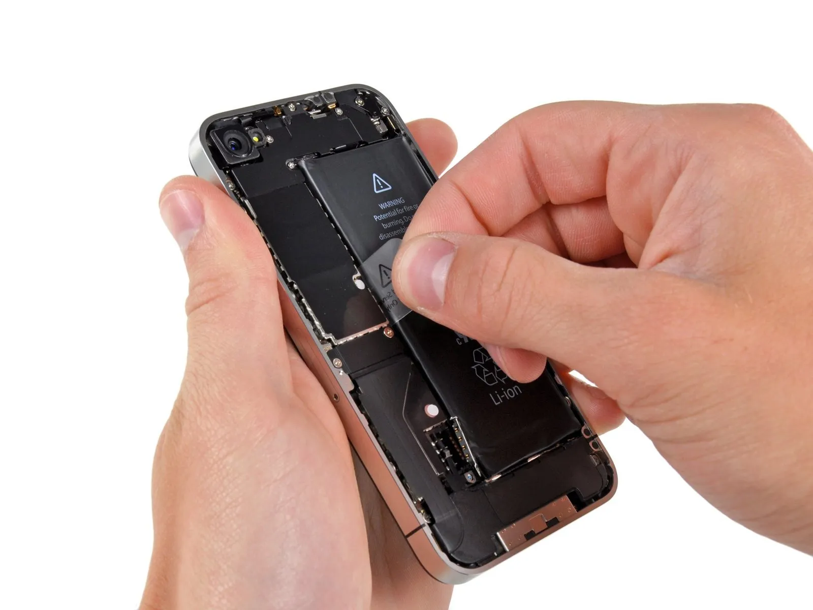
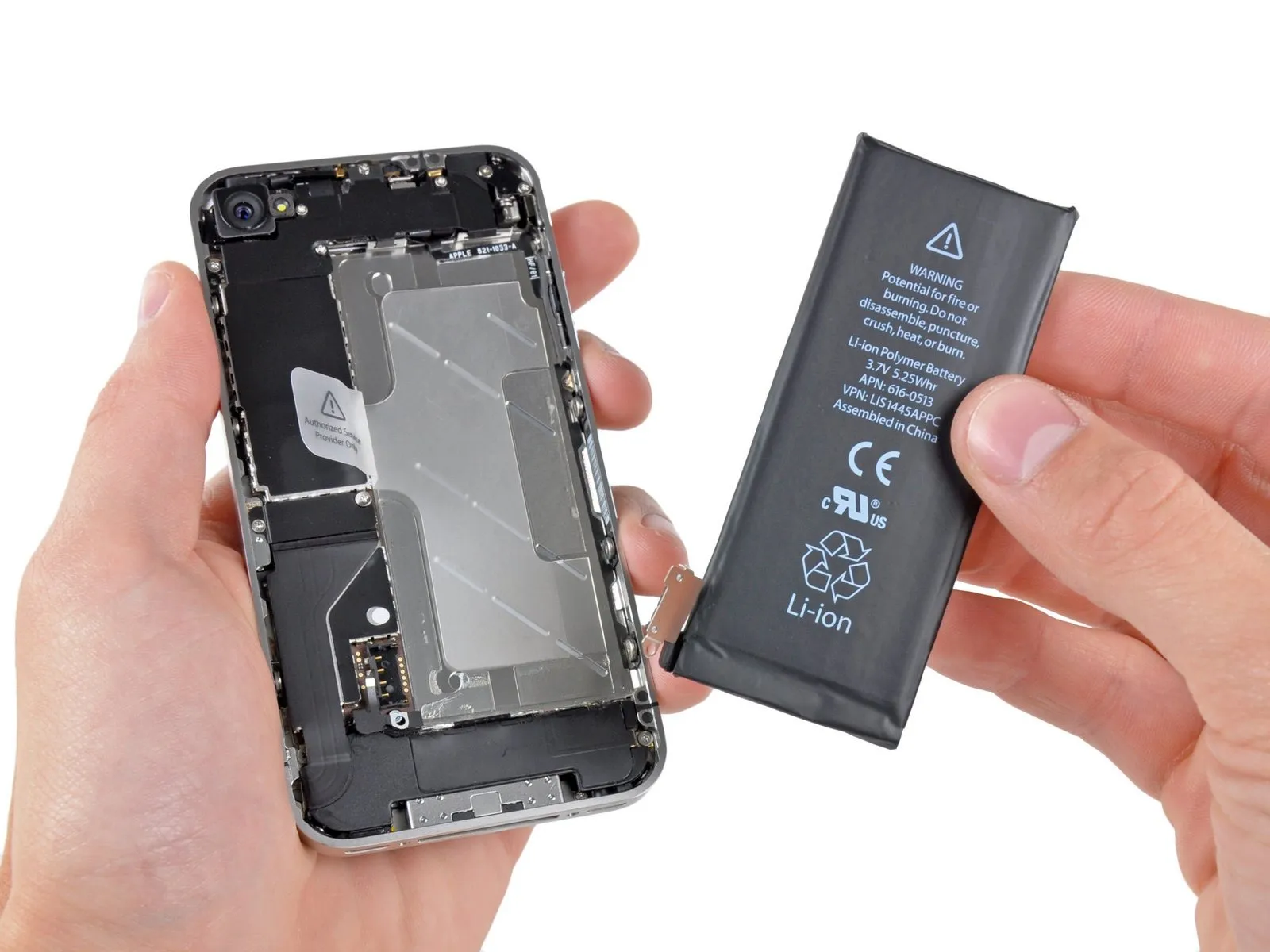
Carefully extract the battery from the iPhone by utilizing the provided transparent plastic tab to raise it.
Should the battery retaining tab fracture prior to separation, introduce a small quantity of isopropyl alcohol with a concentration exceeding 90% beneath the fractured tab edge; allow approximately one minute for the adhesive to soften. Then, gently insert a spudger beneath the battery tab to disengage the adhesive.
To avoid damage, do not attempt to force the battery free using leverage elsewhere. If the adhesive still resists separation, add additional drops of alcohol to soften it. Ensure the pry tool does not puncture or bend the battery during removal.
To prevent damage, ensure any residual alcohol solution is completely removed by wiping or by allowing it to evaporate fully prior to battery installation.
Carefully discard the protective plastic packaging that accompanied the new battery, ensuring you avoid any contact with the ribbon cable during removal.
Ensure the red contact clip is correctly situated adjacent to the battery connector prior to reattaching the battery connector.
To prevent wireless interference, thoroughly remove any residue from metal surfaces that will touch each other during reassembly, using a cleaning agent like Windex.
Following reassembly, execute a full system reset to proactively avoid potential problems and streamline any subsequent diagnostic procedures.
Carefully extract the battery from the iPhone by utilizing the provided transparent plastic tab to raise it.
Should the battery retaining tab fracture prior to separation, introduce a small quantity of isopropyl alcohol with a concentration exceeding 90% beneath the fractured tab edge; allow approximately one minute for the adhesive to soften. Then, gently insert a spudger beneath the battery tab to disengage the adhesive.
To avoid damage, do not attempt to force the battery free using leverage elsewhere. If the adhesive still resists separation, add additional drops of alcohol to soften it. Ensure the pry tool does not puncture or bend the battery during removal.
To prevent damage, ensure any residual alcohol solution is completely removed by wiping or by allowing it to evaporate fully prior to battery installation.
Carefully discard the protective plastic packaging that accompanied the new battery, ensuring you avoid any contact with the ribbon cable during removal.
Ensure the red contact clip is correctly situated adjacent to the battery connector prior to reattaching the battery connector.
To prevent wireless interference, thoroughly remove any residue from metal surfaces that will touch each other during reassembly, using a cleaning agent like Windex.
Following reassembly, execute a full system reset to proactively avoid potential problems and streamline any subsequent diagnostic procedures.
Step 7 | Vibrator

Using a 5/32-inch hex key, carefully tighten the four M4x8mm screws securing the fan assembly to the heatsink, ensuring a torque of 4.5 in-lbs to prevent damage.
Detach the vibrator from the inner frame by unscrewing the two fasteners.
Detach the vibrator from the inner frame by unscrewing the two fasteners.
- Use a Phillips screwdriver, size 6 mm.
- Use a Phillips screwdriver with a 1.4 mm tip.
Step 8
Using a 5/32-inch hex key, carefully tighten the four mounting screws securing the fan assembly to the motor housing, ensuring each is snug but not over-tightened to prevent damage; observe a torque of 6 in-lbs per screw.
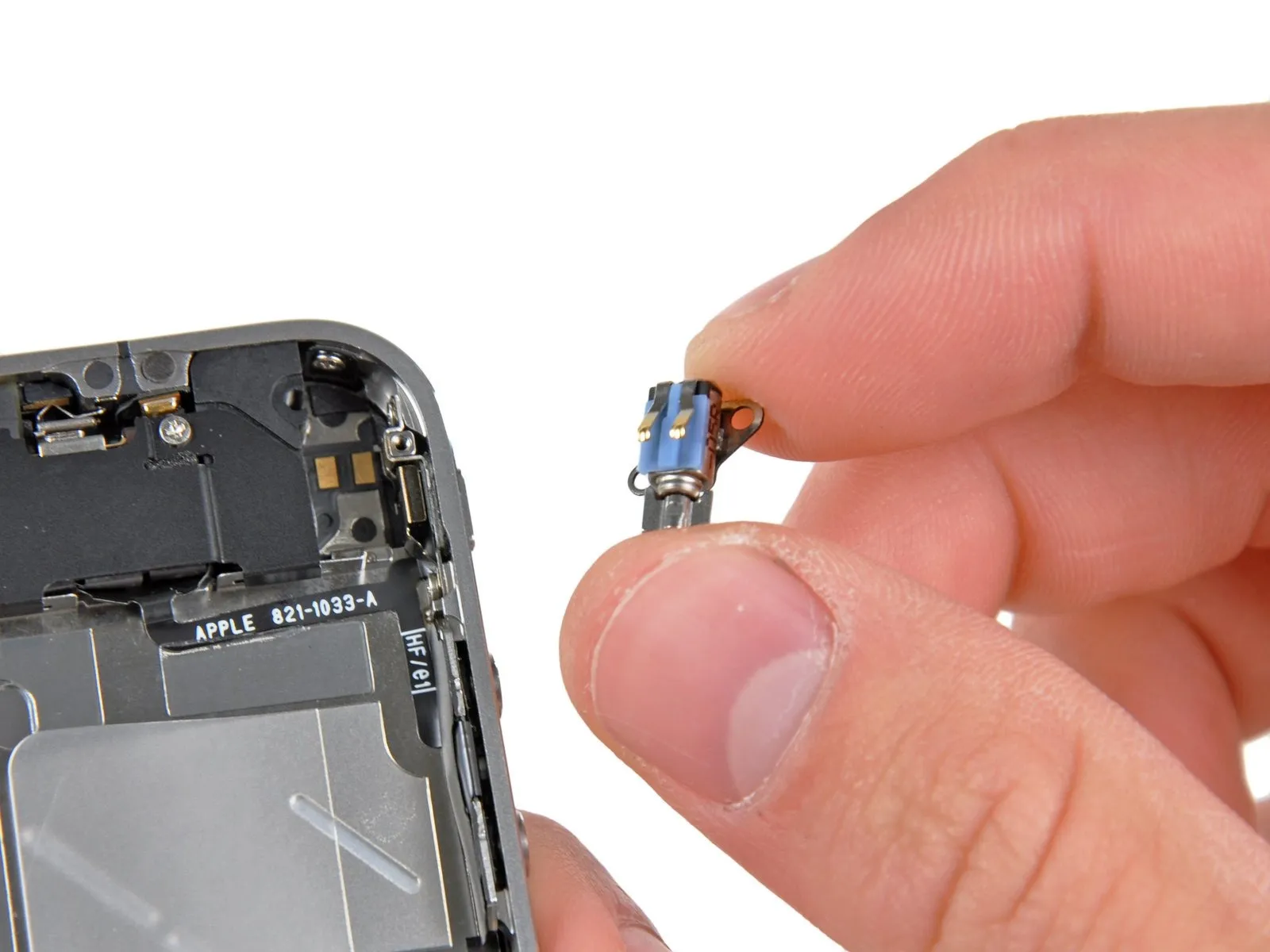
Carefully extract the vibrator component from within the inner case.
Carefully extract the vibrator component from within the inner case.