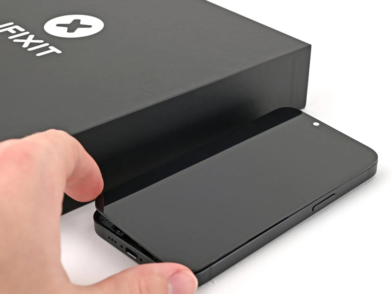
iPhone 17e Screen Replacement
This detailed procedure assists in substituting a damaged, fractured, or unresponsive display assembly on an iPhone 17e.
Acquiring fresh screen adhesive is essential for the successful completion of this repair process.
- Important considerations are outlined below.Due to the inability to isolate the battery during this procedure, exercise extreme caution and avoid utilizing metallic implements or making contact with any exposed electrical connections within the iPhone.
Post-repair, it is necessary to adjust the settings of an authentic Apple display through the Repair Assistant application.
The accompanying photographic documentation originates from a variant model; while minor aesthetic differences may be apparent, they do not impact the repair steps.
Step 1 | Before you begin


- Initiate the power-off sequence by concurrently depressing the power button and any volume button, subsequently sliding to deactivate the phone's power.
- Simultaneous pressure on the power button and a volume button, followed by a sliding motion, is required to correctly shut down the device.
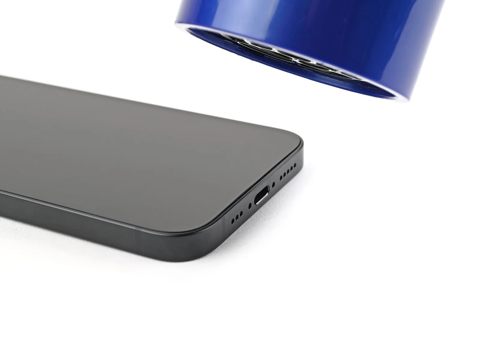
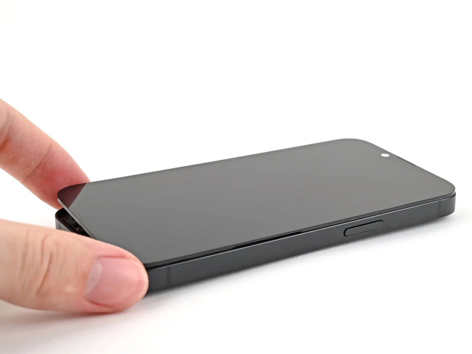
Step 2 | Tape over any cracks


- A sufficiently sized, uninterrupted surface region proximate to the lower edge is required to establish a secure attachment point for the suction cup.
Step 3 | Remove the pentalobe screws


Step 4 | Mark your opening picks


- Using a measuring tool, determine a distance of precisely 3 millimeters.Indicate this 3-millimeter measurement on the pick's tip with a durable, permanent marker.For enhanced precision, consider marking other points on the pick with varying distances.
- As an alternative method for limiting insertion depth, securely affix a coin.
- The coin should be positioned 3 millimeters away from the pick's pointed end.This coin placement serves as a physical depth gauge during the opening process.Adhering to these guidelines minimizes the risk of component damage during device separation.
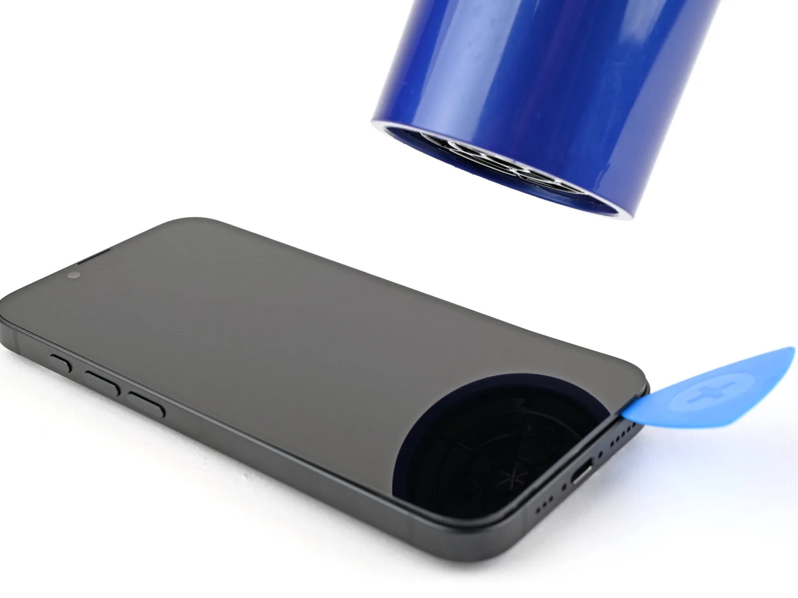
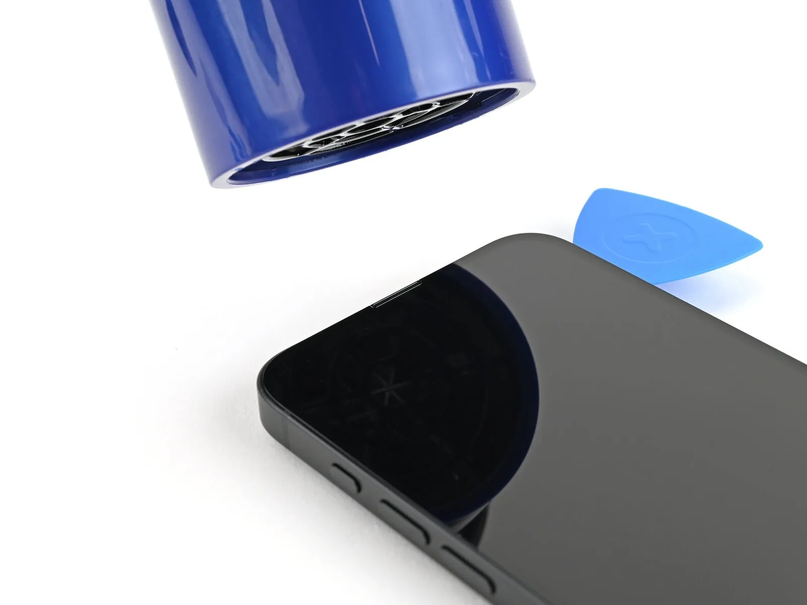
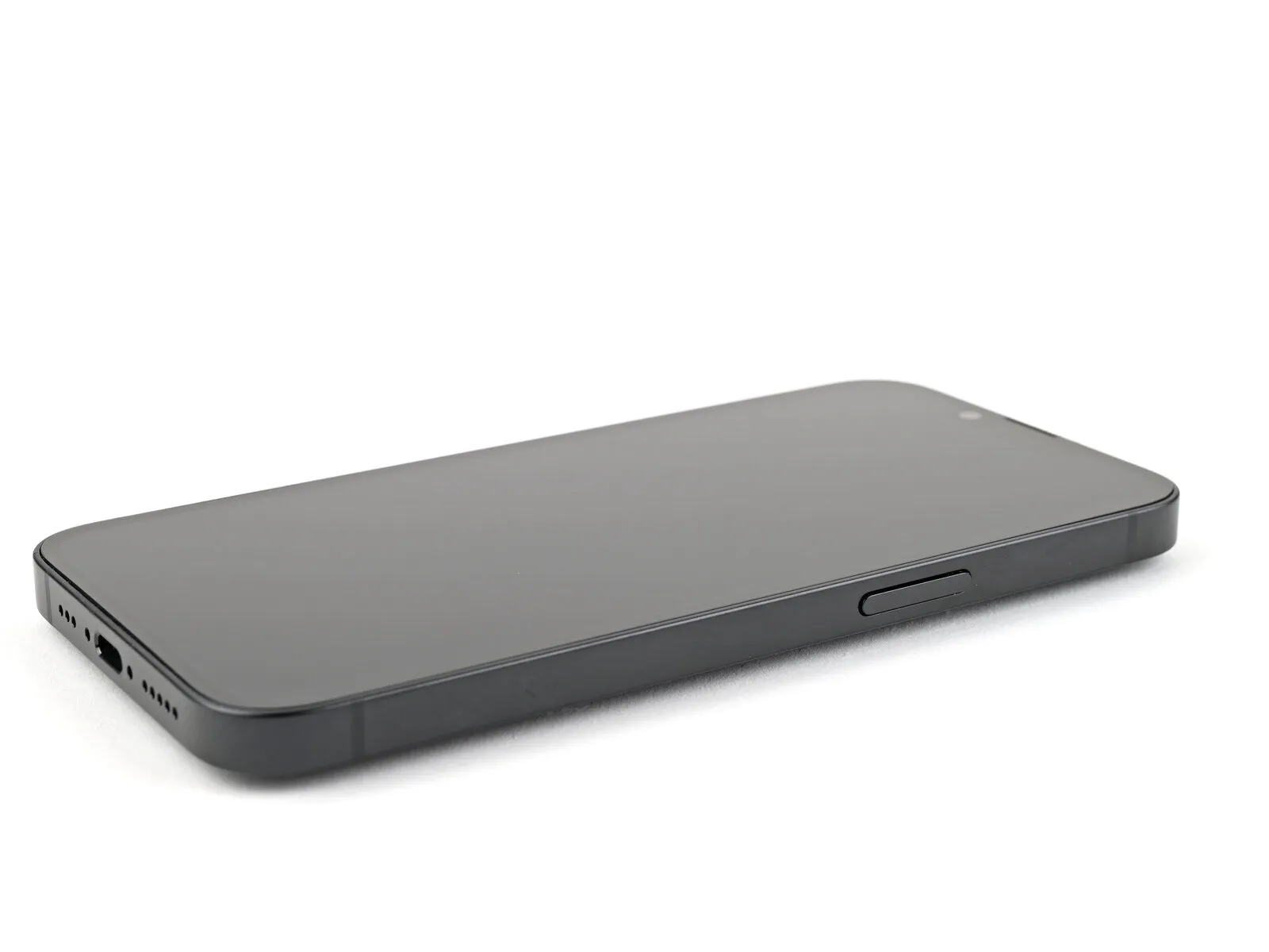
Step 5 | Heat the bottom edge
- Apply warmth to the screen's lower border utilizing a hair dryer or heat gun, ensuring the surface reaches a touch-sensitive temperature.
- As an alternative method, an iOpener can be employed for heating; adhere to the included guidance for proper application and warming.
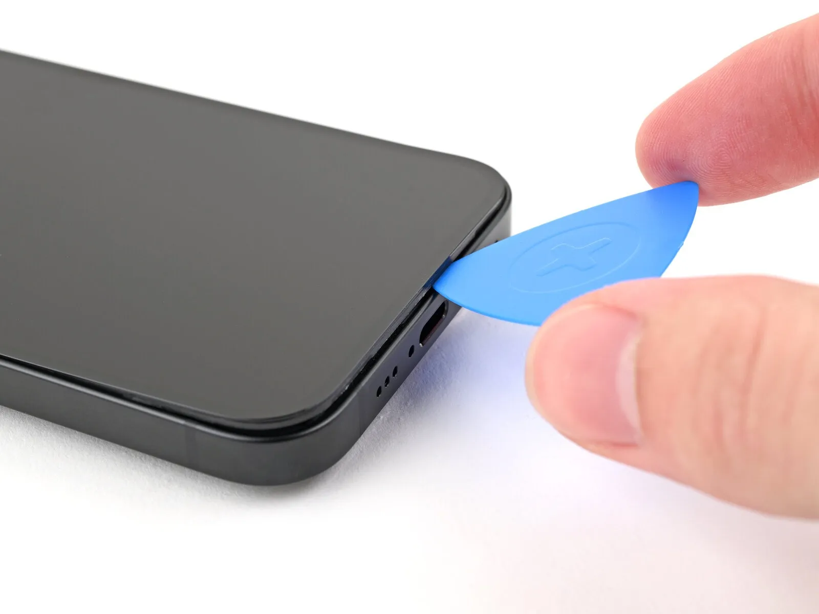
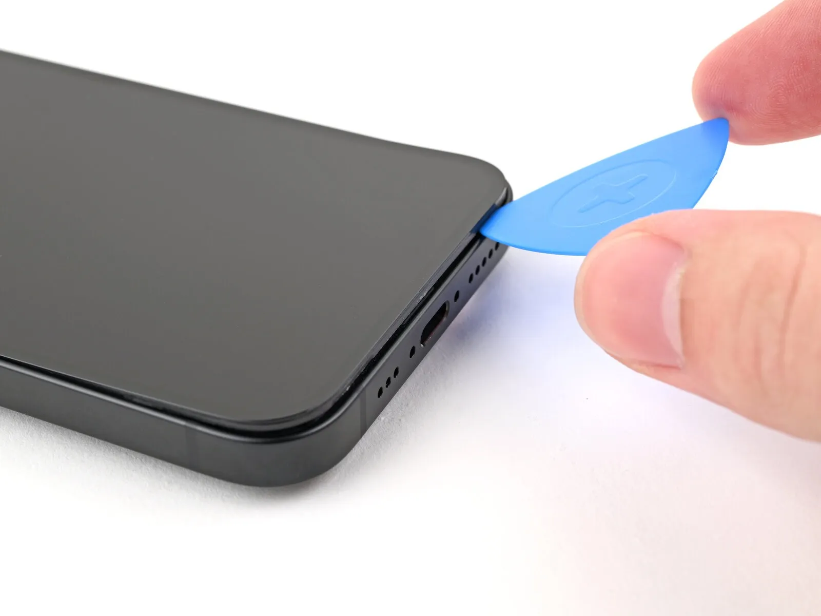
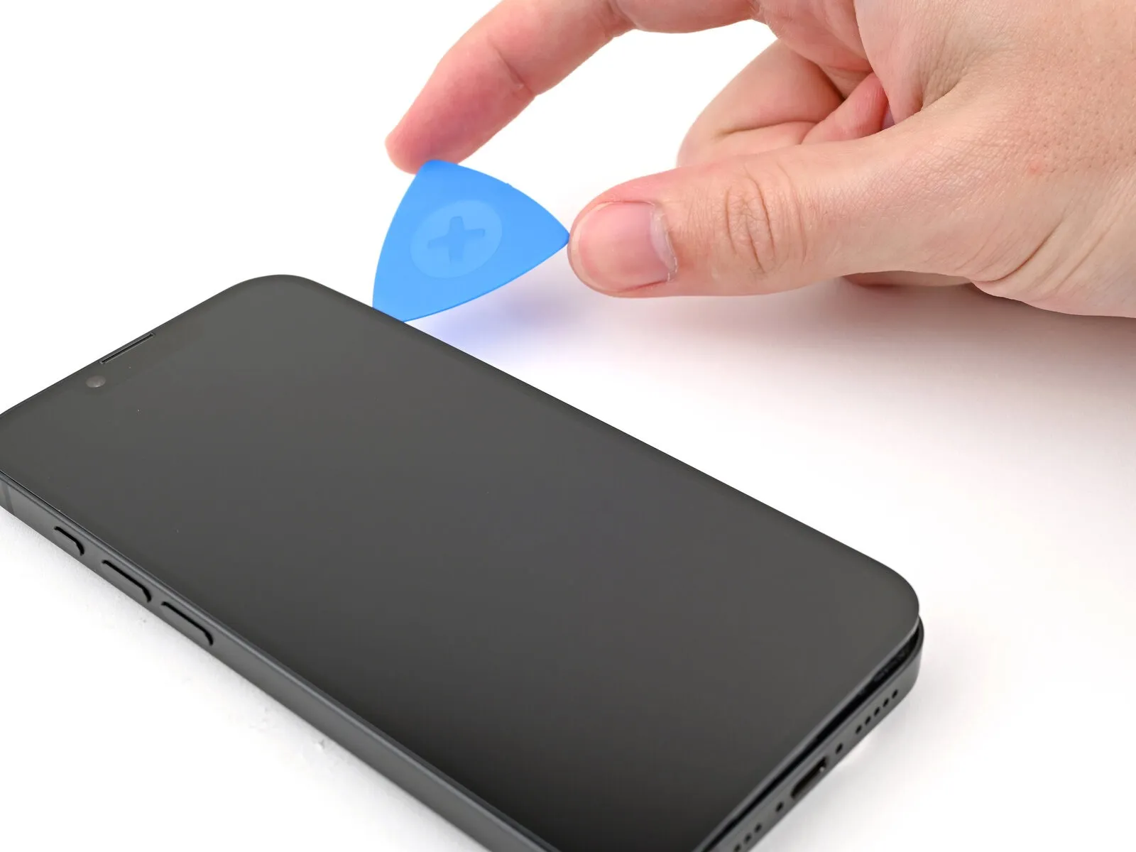
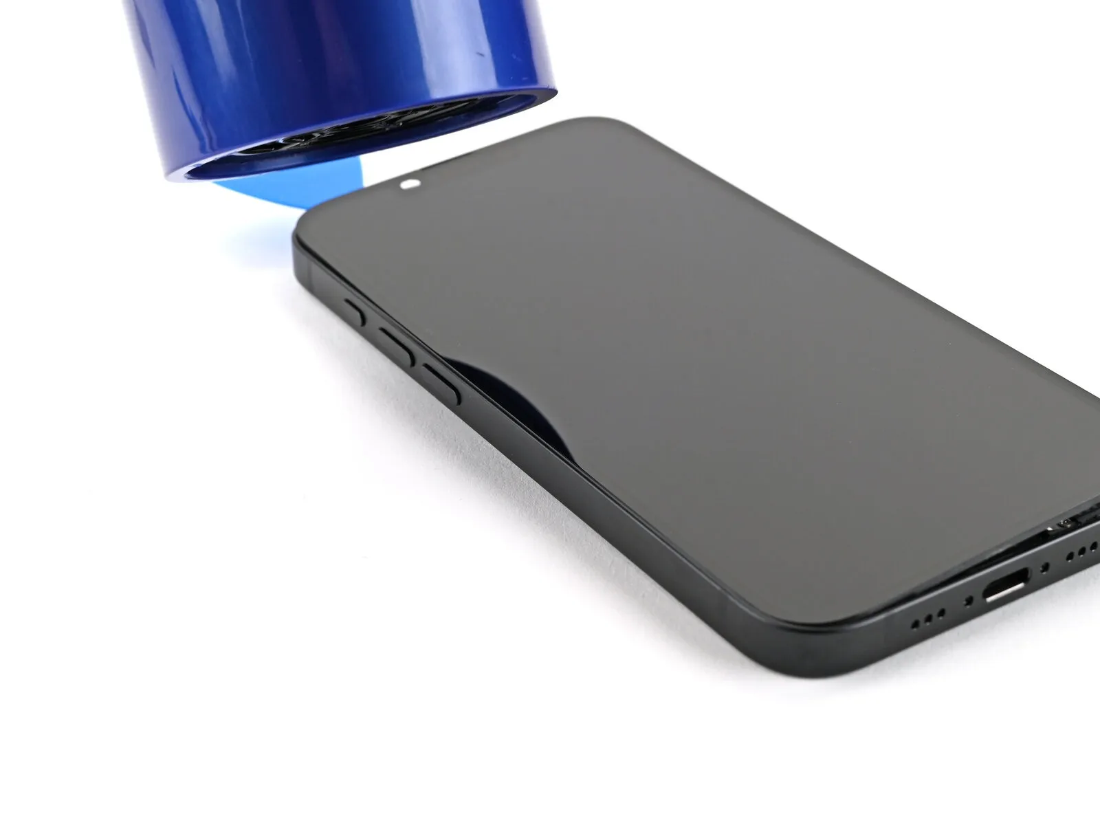
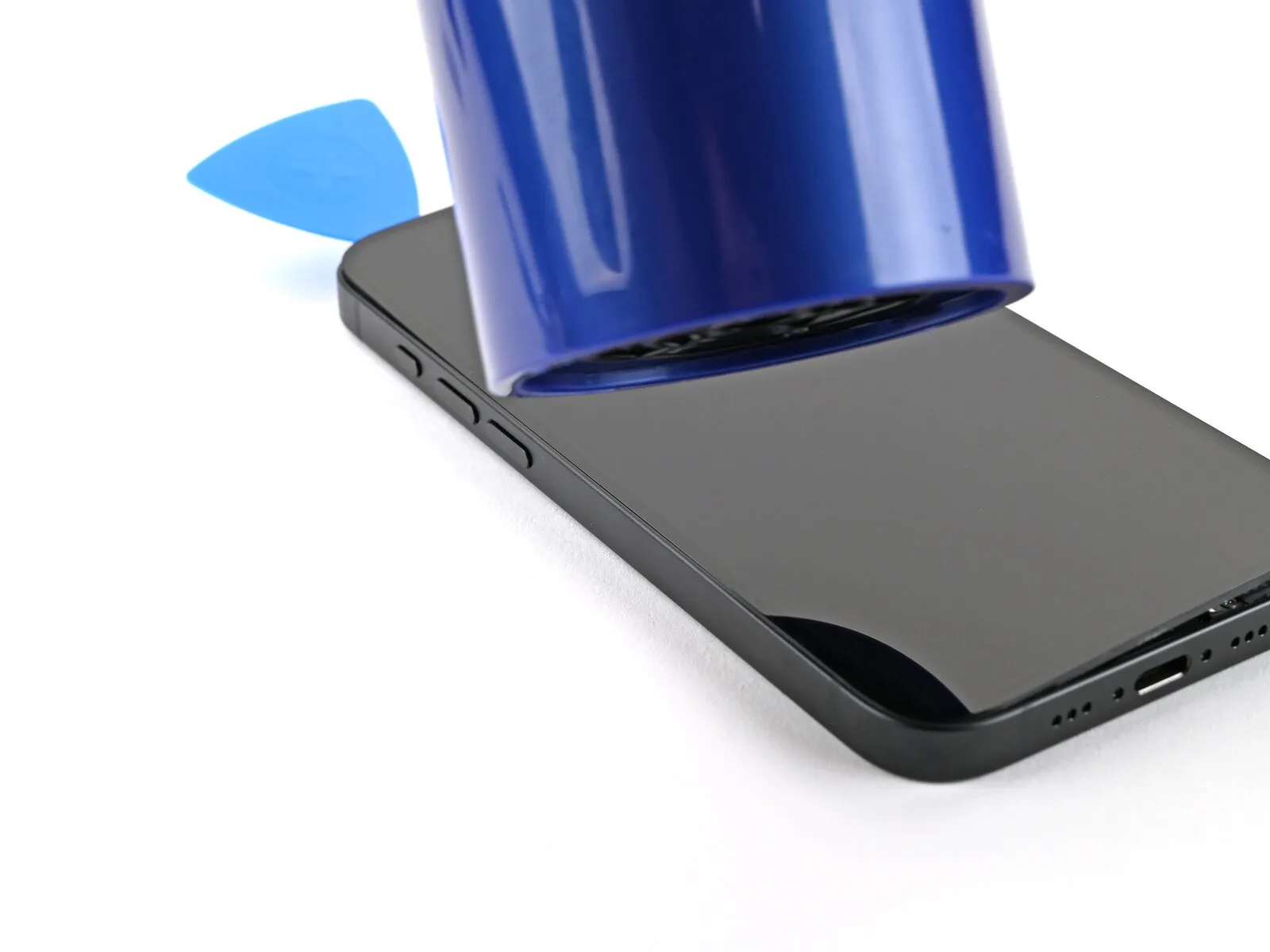
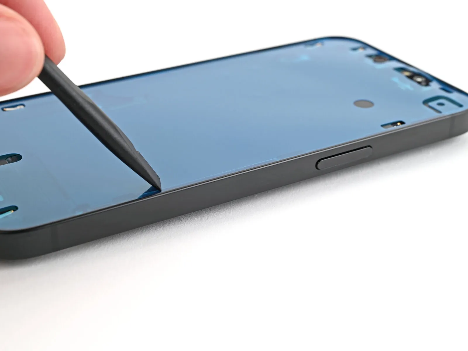
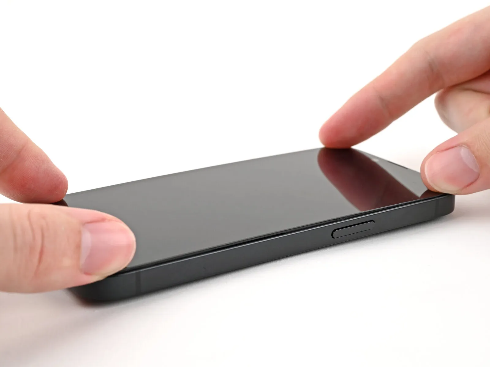
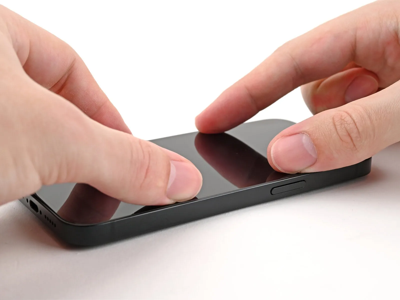
Step 6 | Insert an opening pick
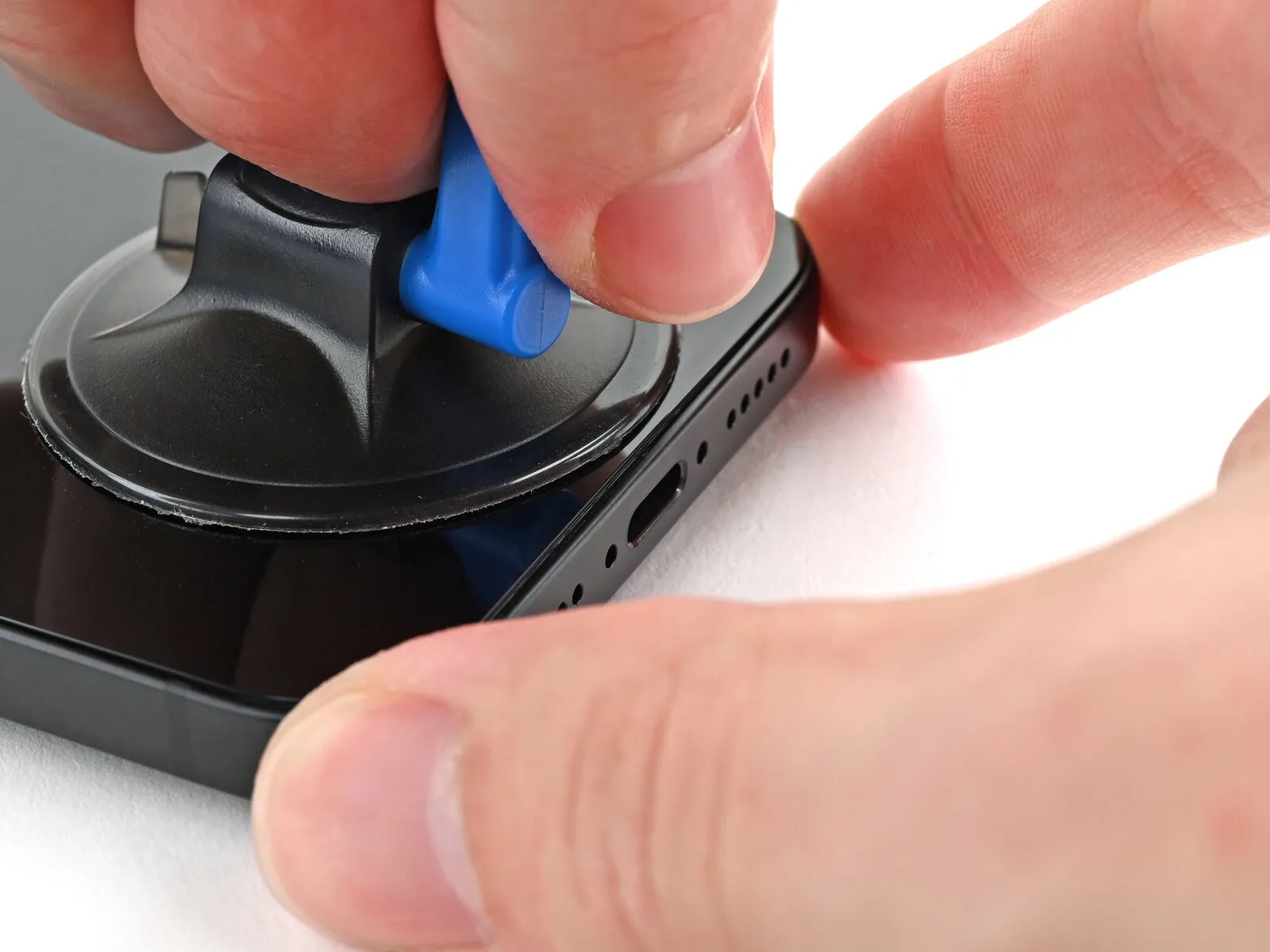
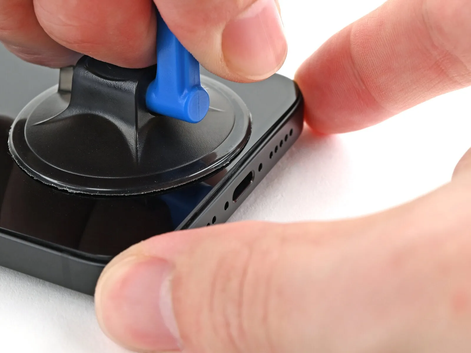
- Maintain downward pressure on the device's frame with one hand while exerting a firm, continuous upward pull on the suction cup's handle.
- This action will generate a separation between the screen assembly and the device's frame.
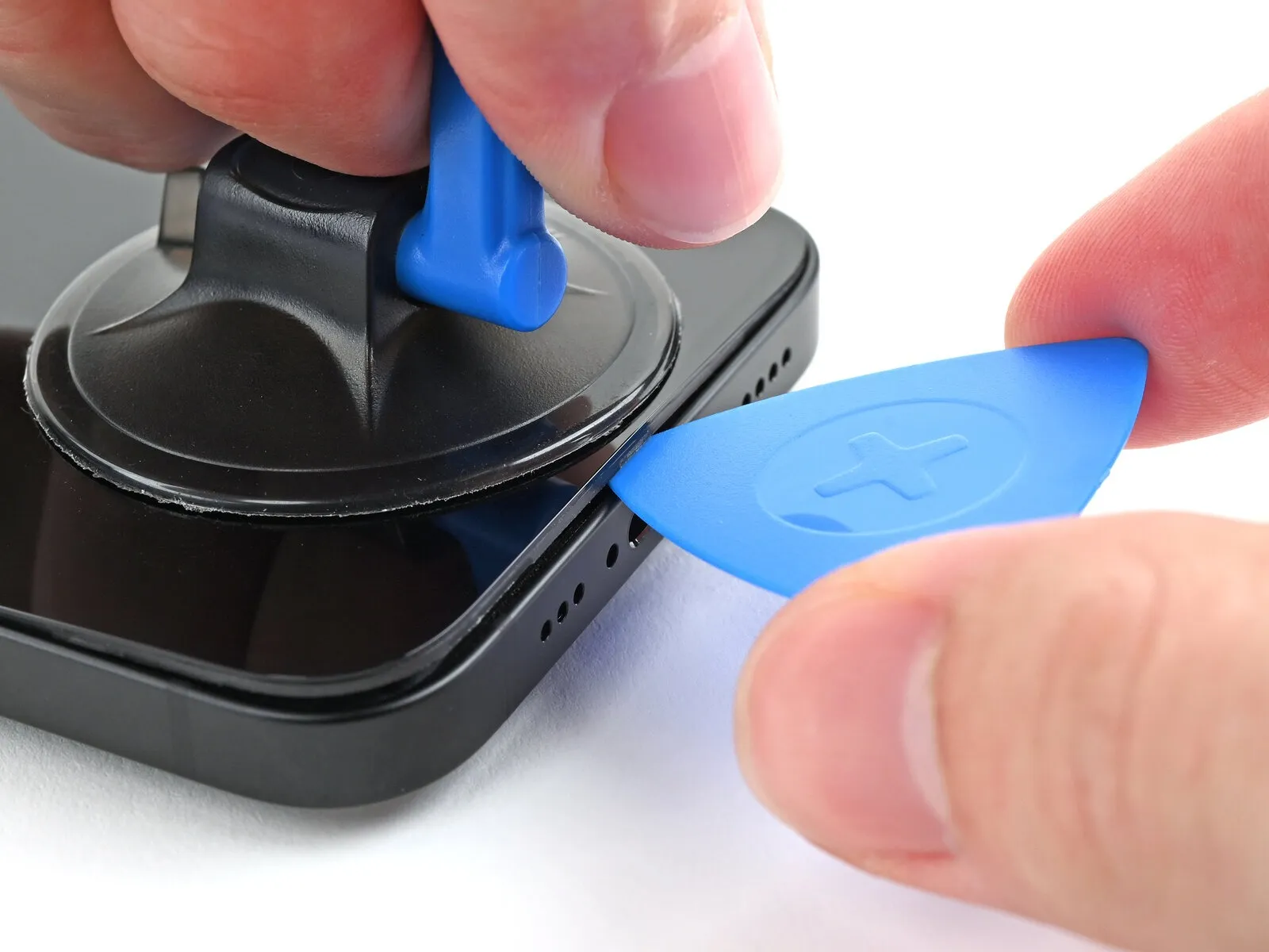
- Introduce the pointed end of another prying tool into the newly formed space.
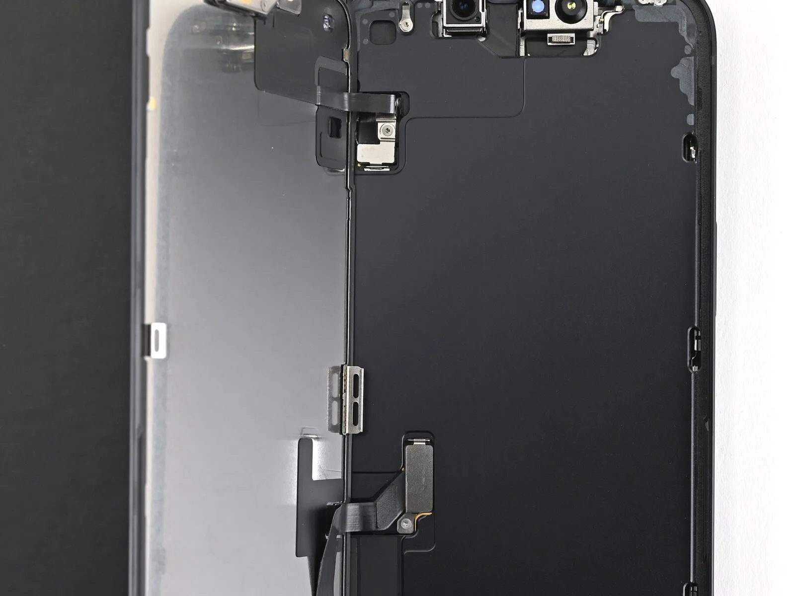
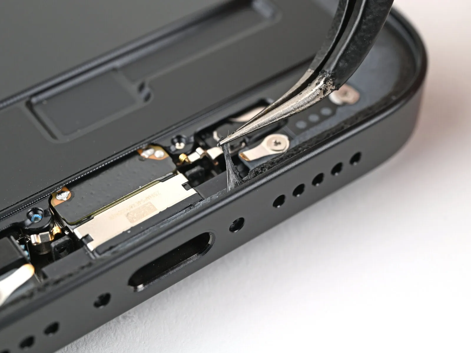
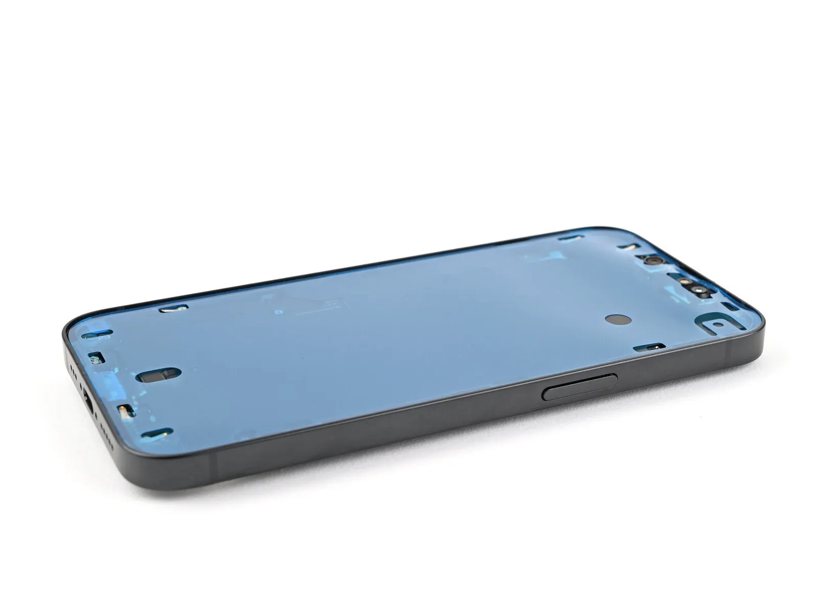
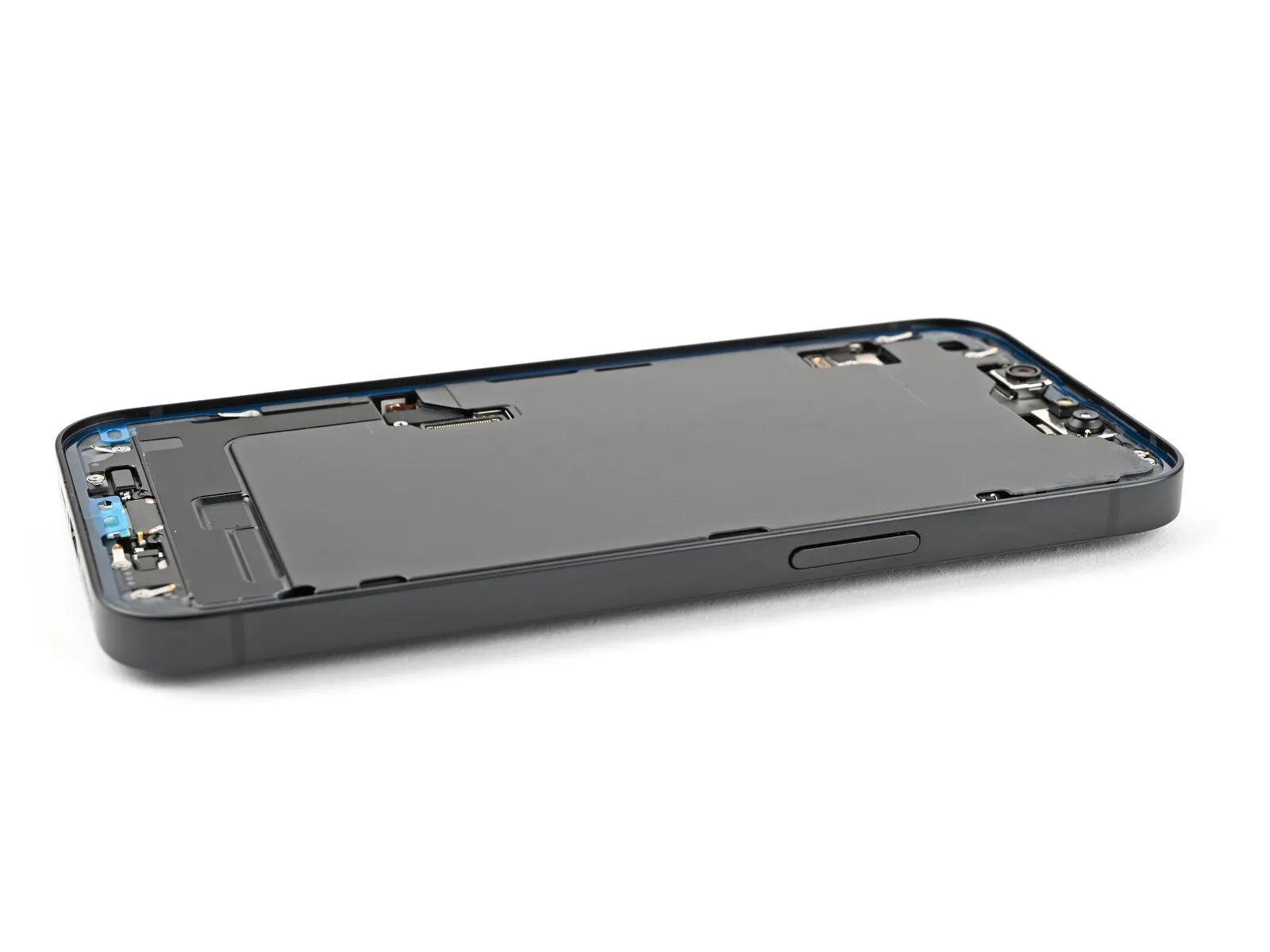
Step 7 | Screen information
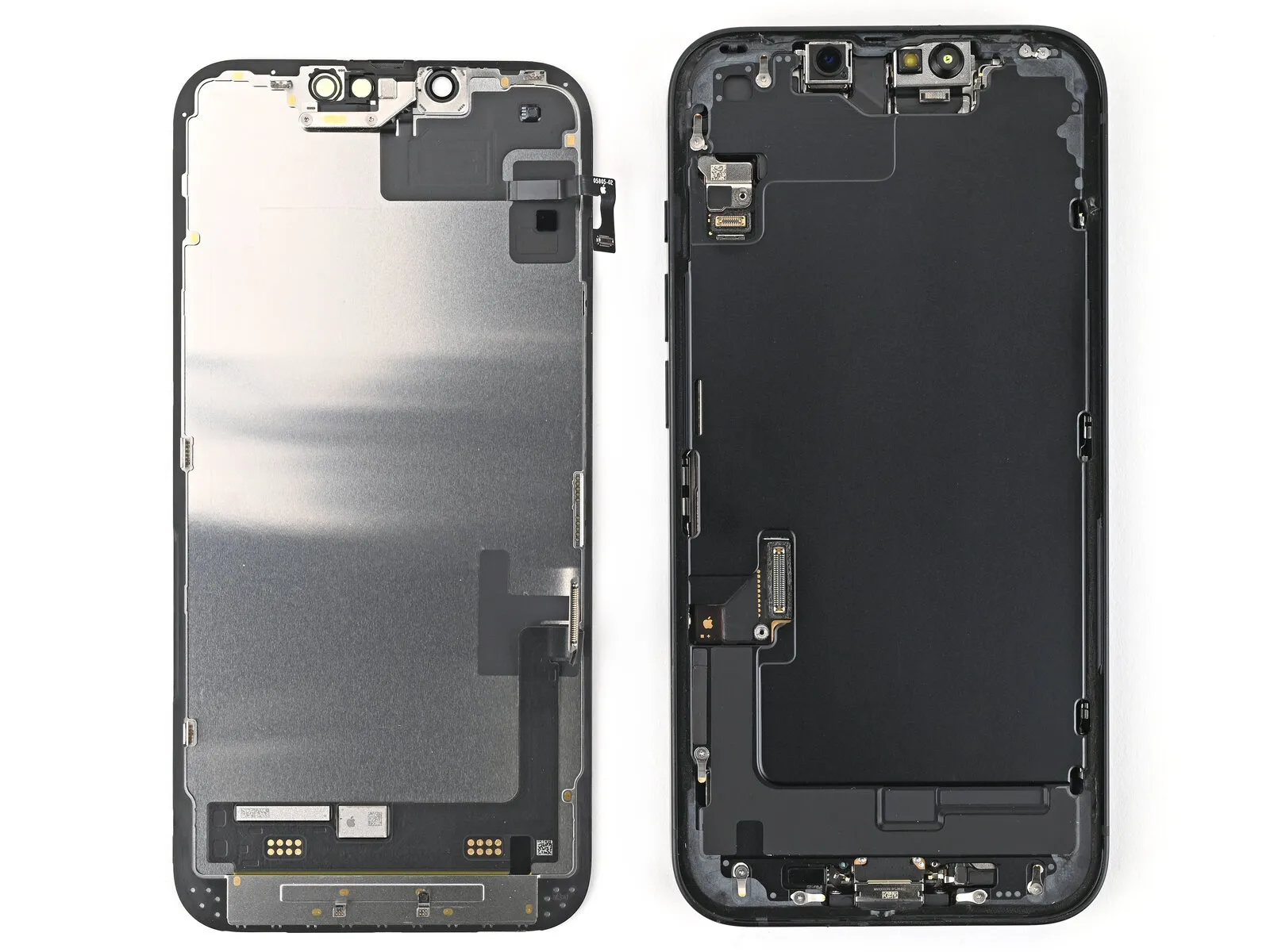
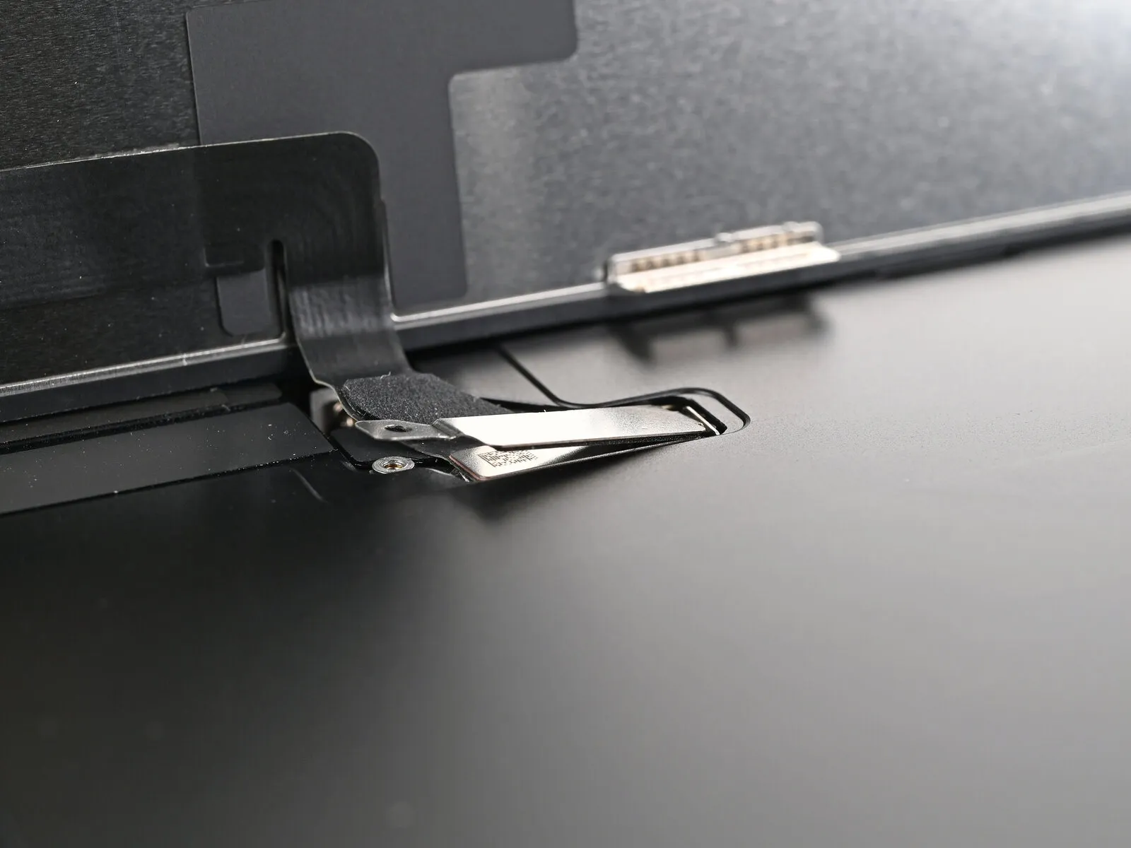
- A series of small, easily-disrupted spring contacts are also present around the phone's outer edge.
- Exercise caution to prevent injury to these components while releasing the screen.
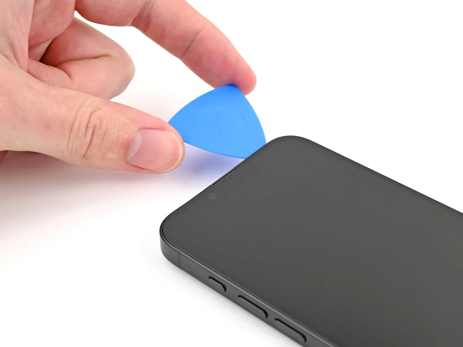
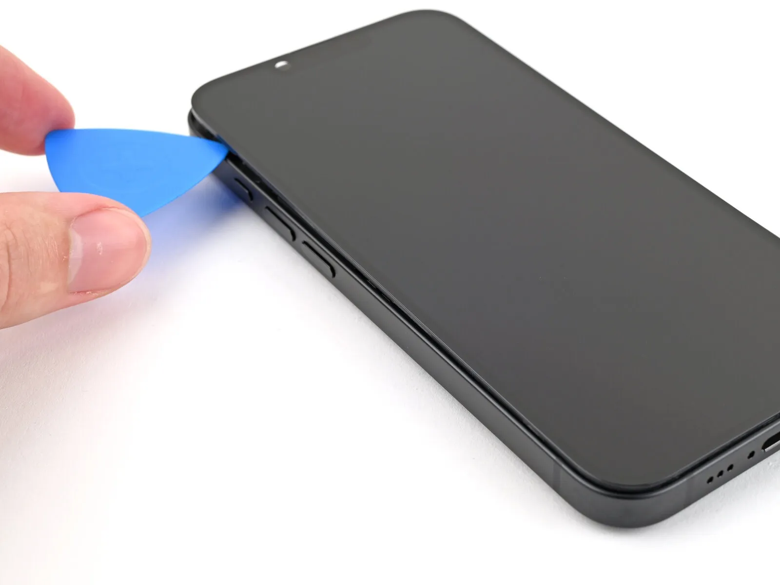
Step 8
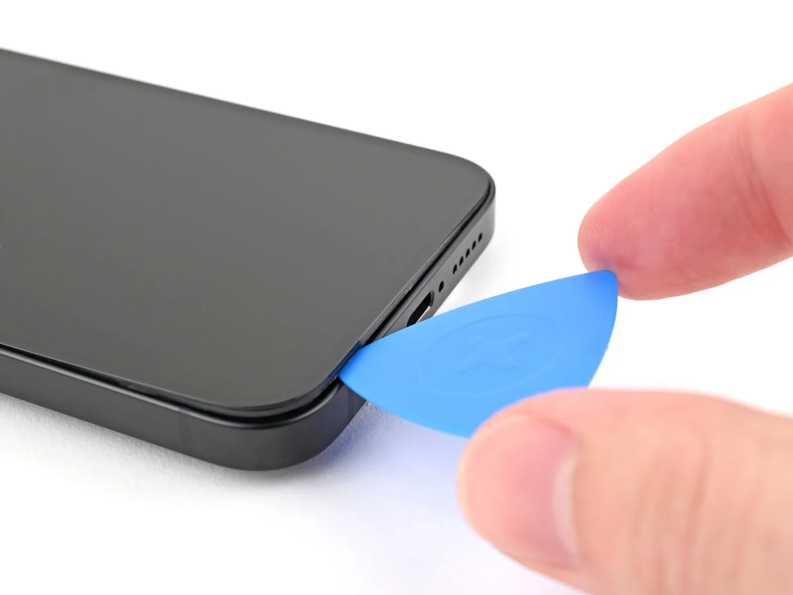
- Maintain the positioning of the opening pick within the lower-right quadrant for subsequent steps.
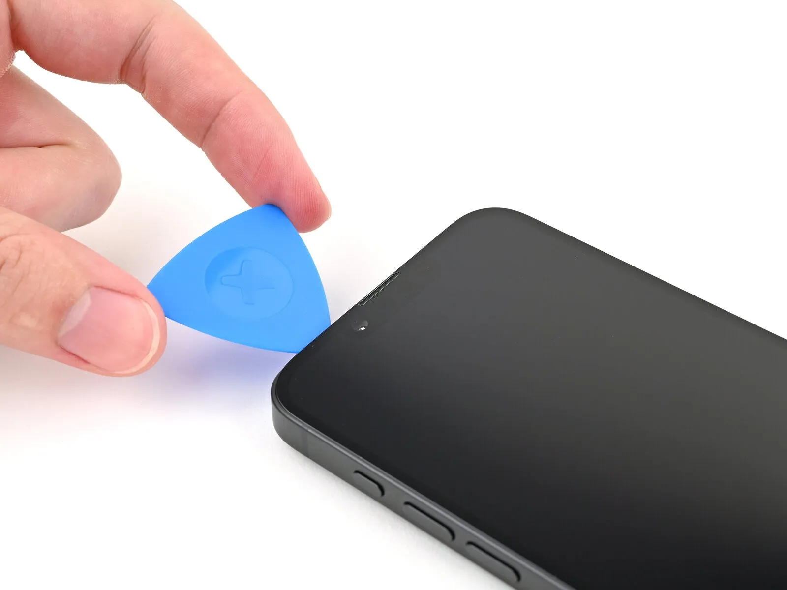
Step 9 | Heat the right edge
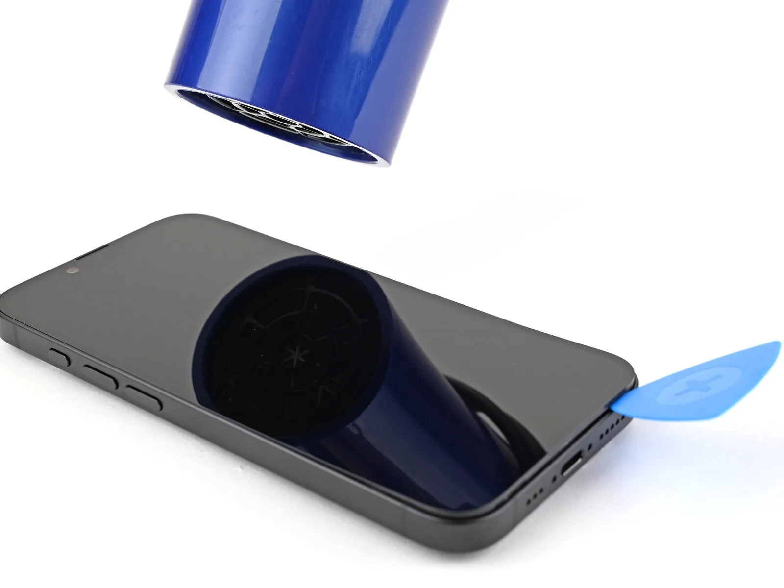
Apply warmth to the screen's right border, ensuring it reaches a temperature that is noticeably warm when touched.
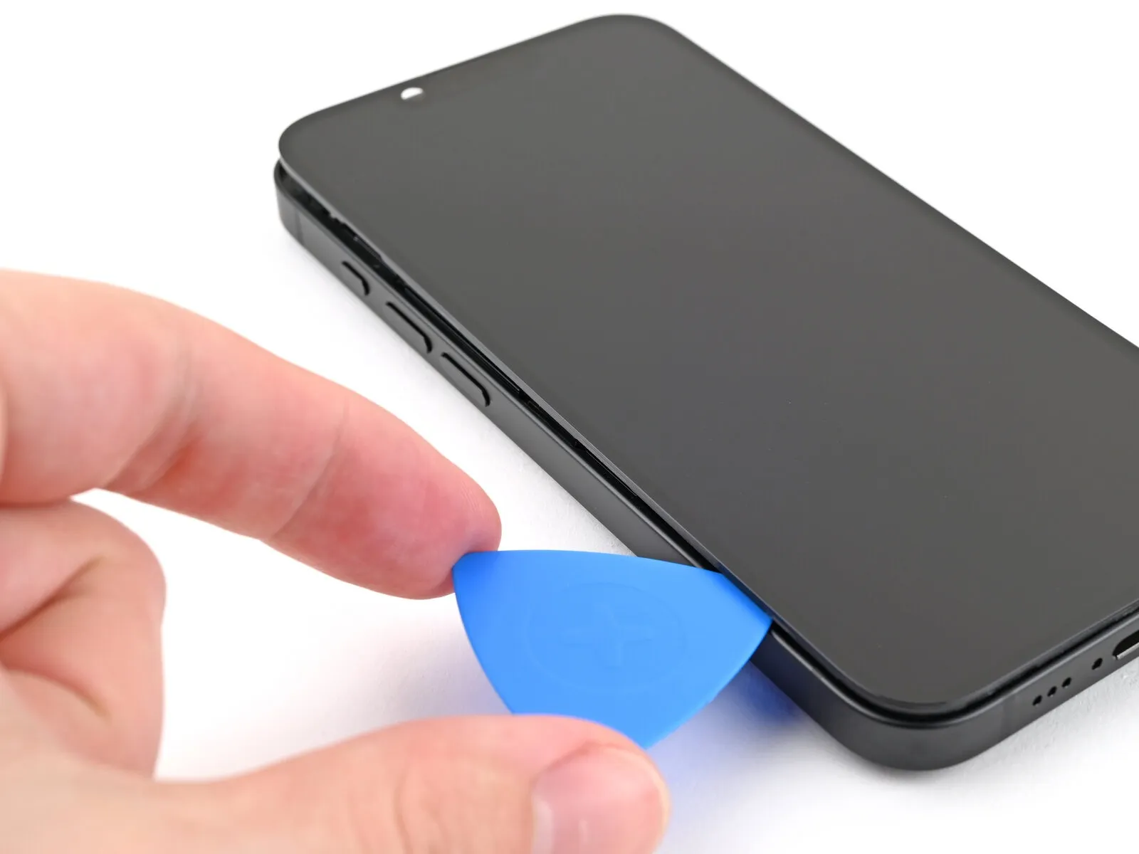
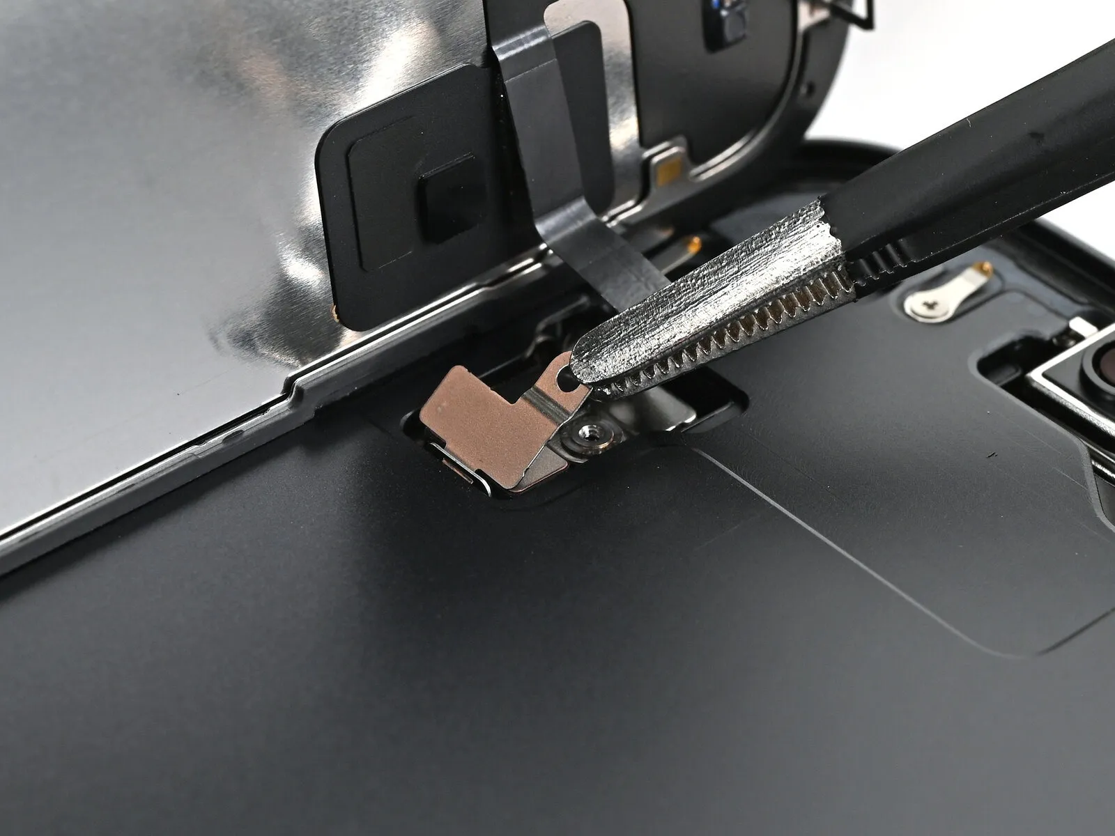
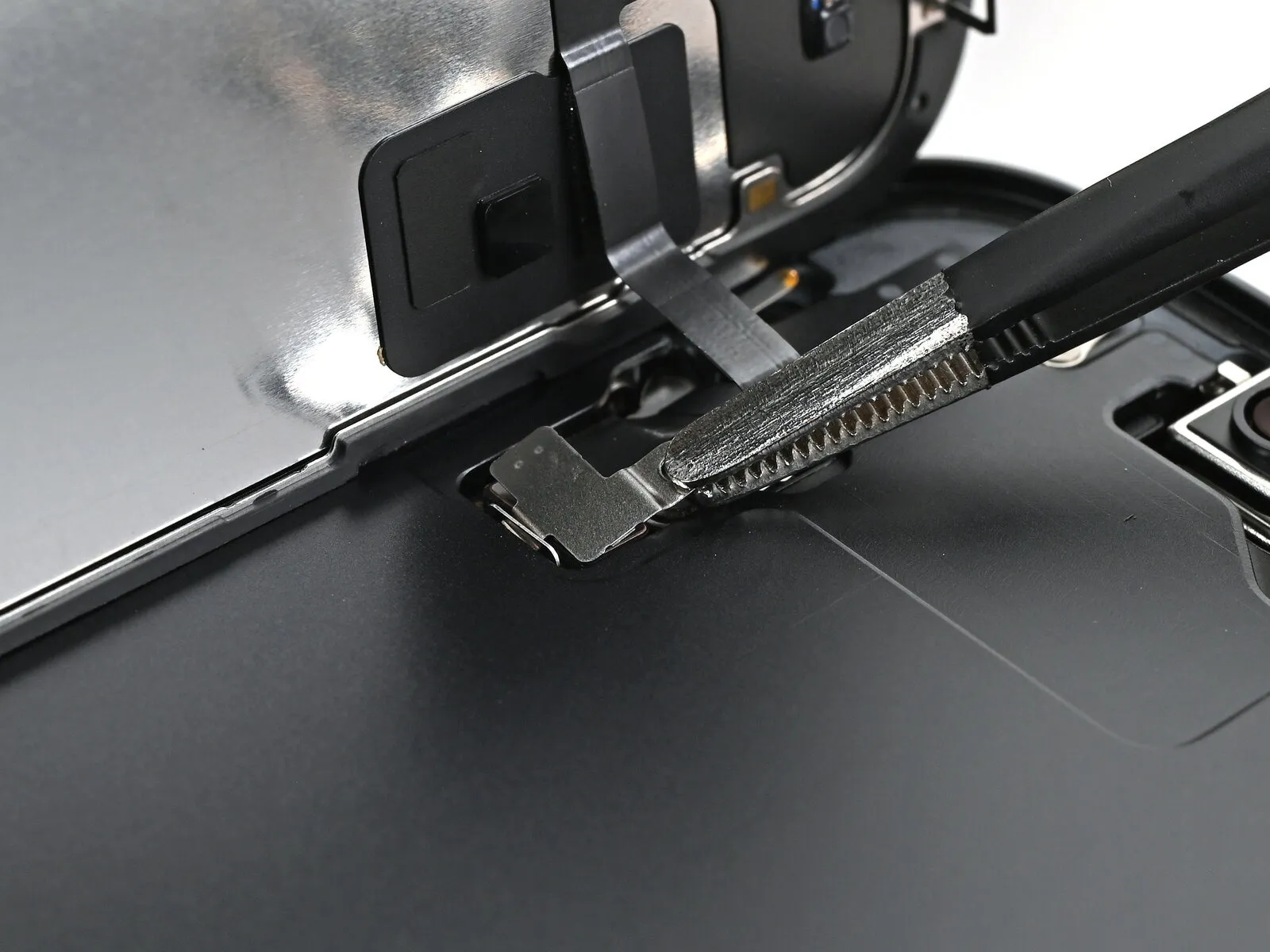
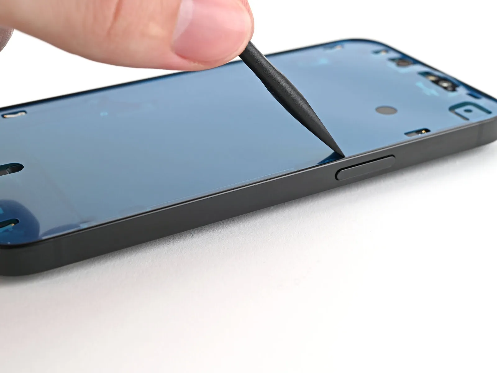
Step 10
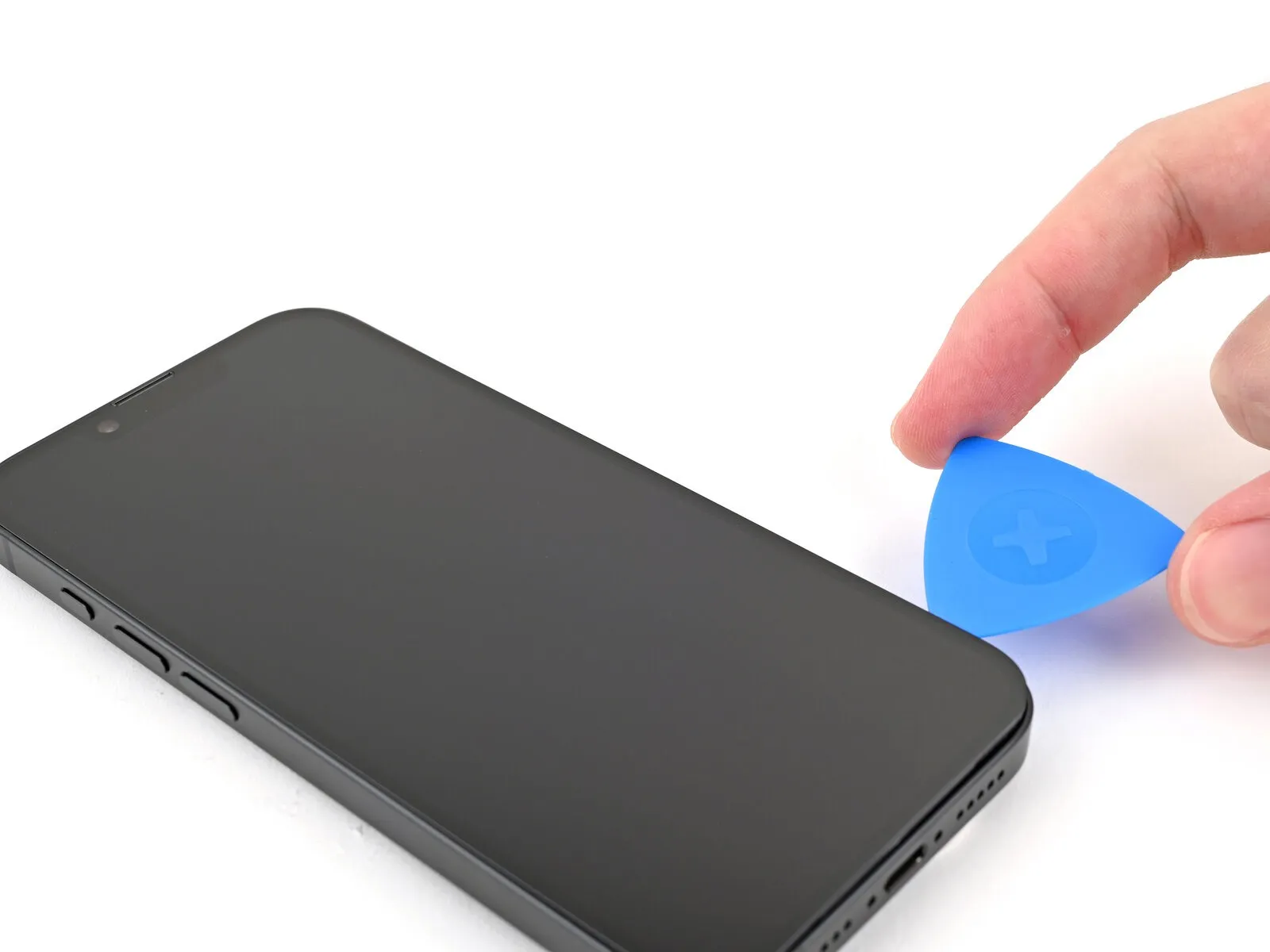
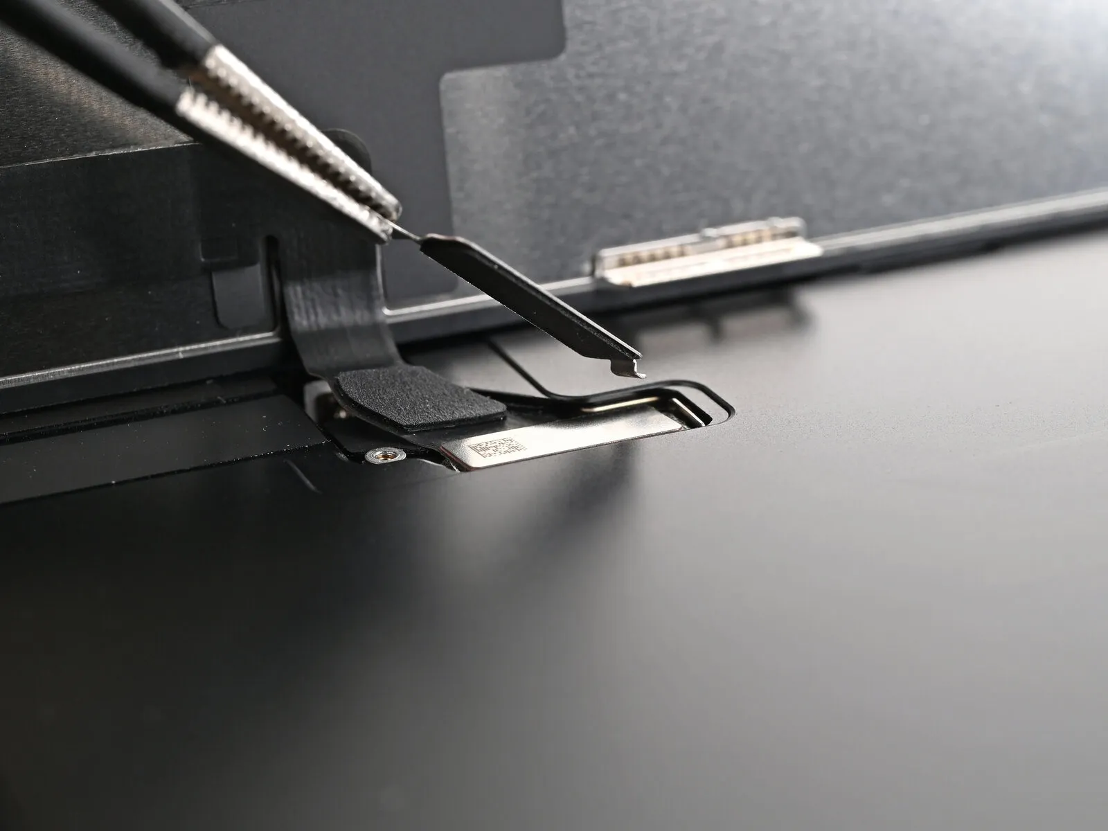
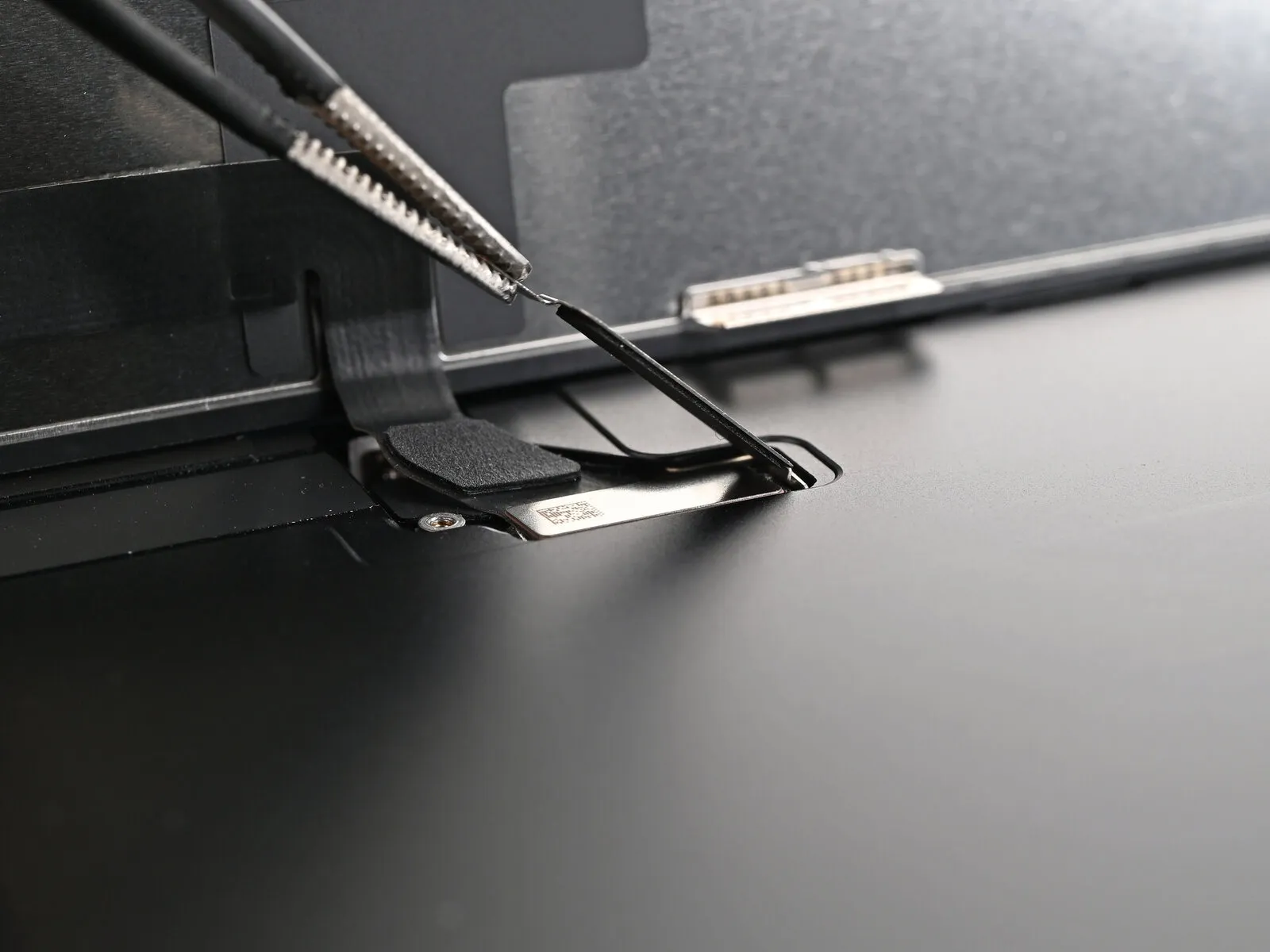
- Employ an opening pick to maneuver along the screen's lower-right corner, progressing upward along the right edge, to sever the adhesive bond and disengage the metallic clip.
Step 11 | Heat the top edge
Apply warmth to the screen's upper border, ensuring it reaches a temperature detectable by touch.Elevate the temperature of the screen's uppermost edge to a point where tactile sensation confirms its warmth.
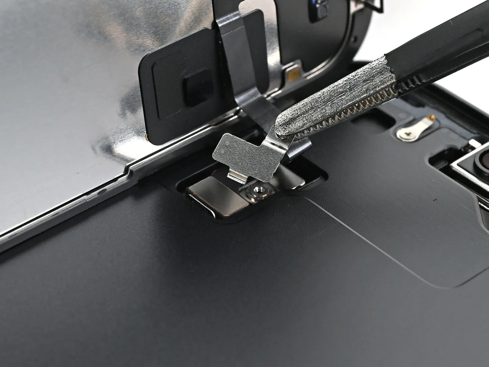
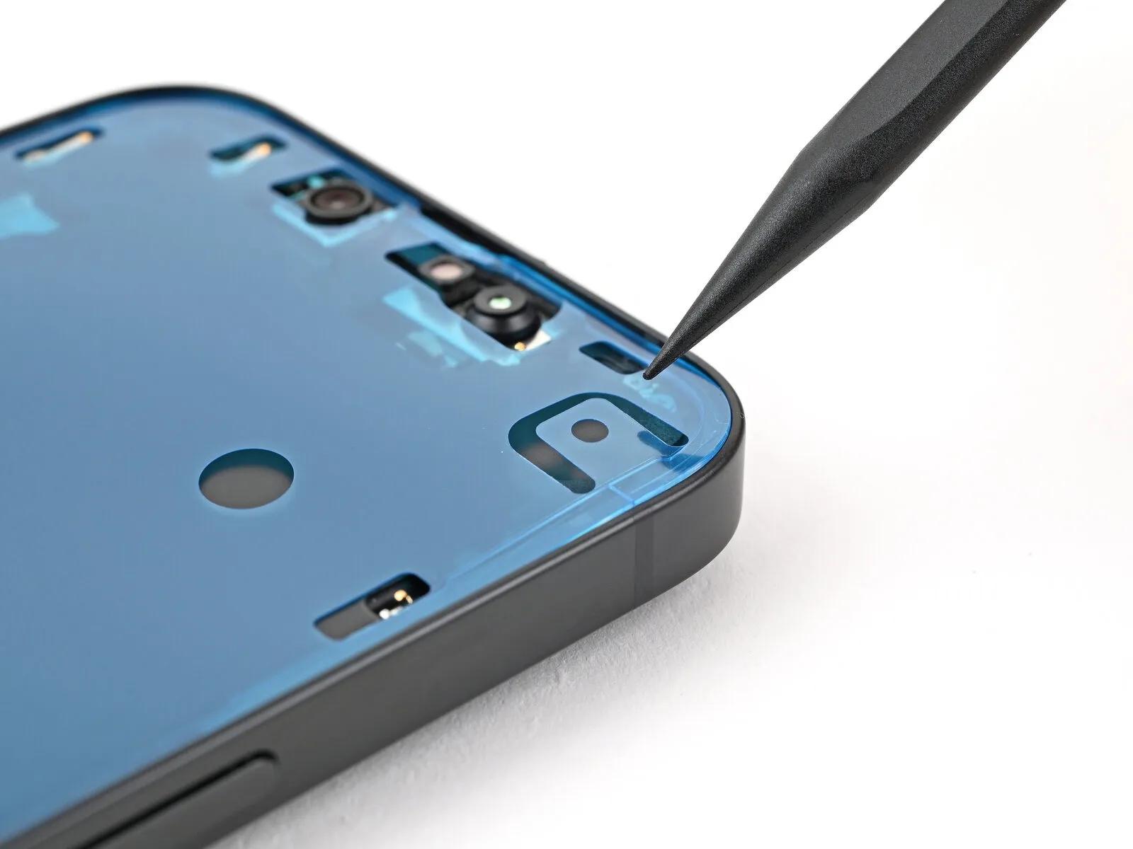
Step 12 | Separate the top adhesive
Employing a prying tool, proceed to disengage the adhesive bond along the upper-right corner and across the entire upper surface, concurrently freeing the two metallic fasteners.
Step 13 | Heat the left edge
Step 14 | Separate the left adhesive
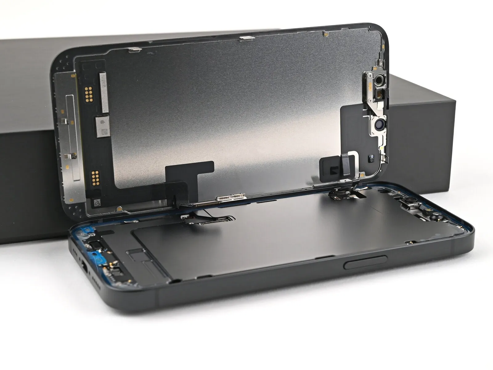
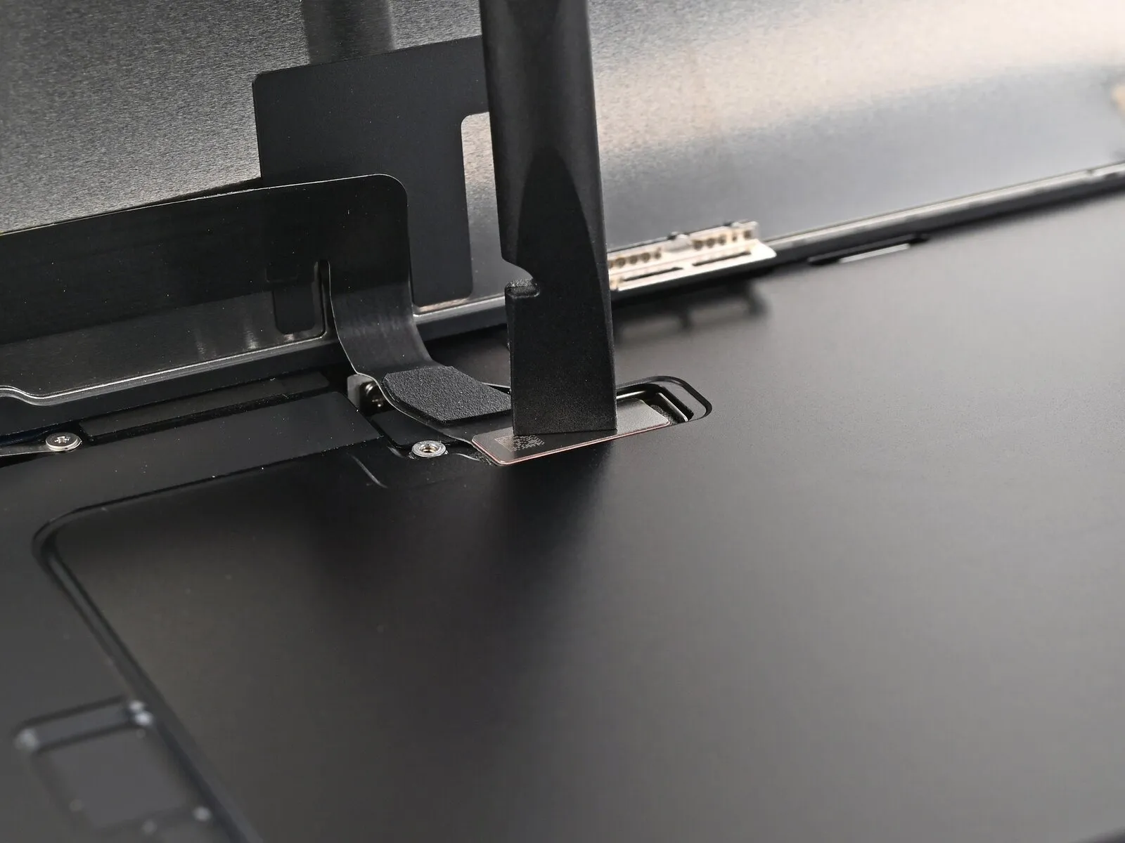
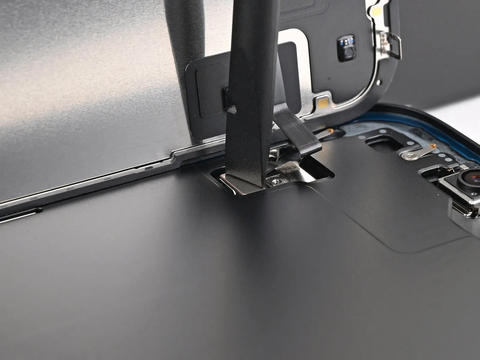
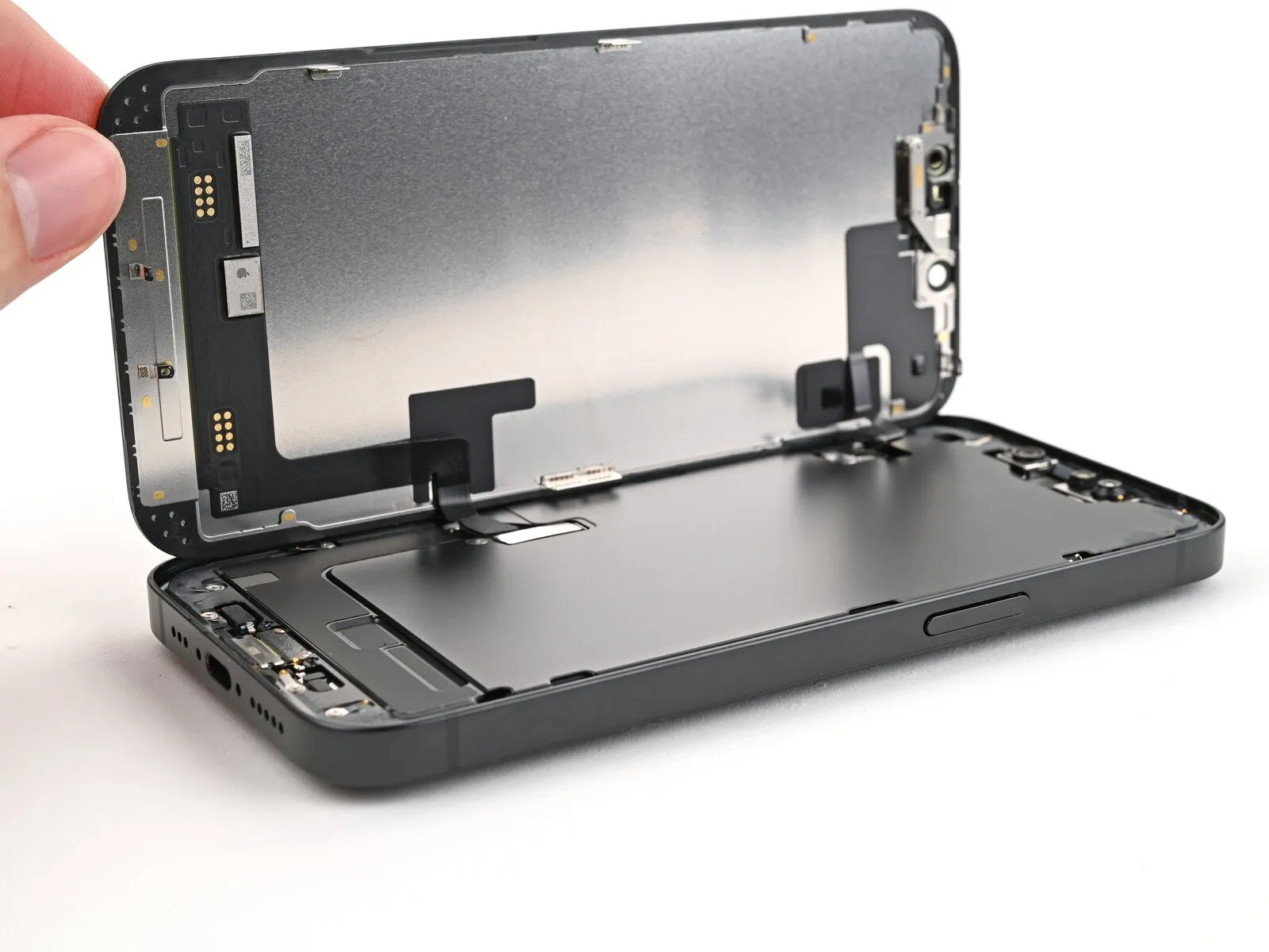
Step 15 | Prop up the screen
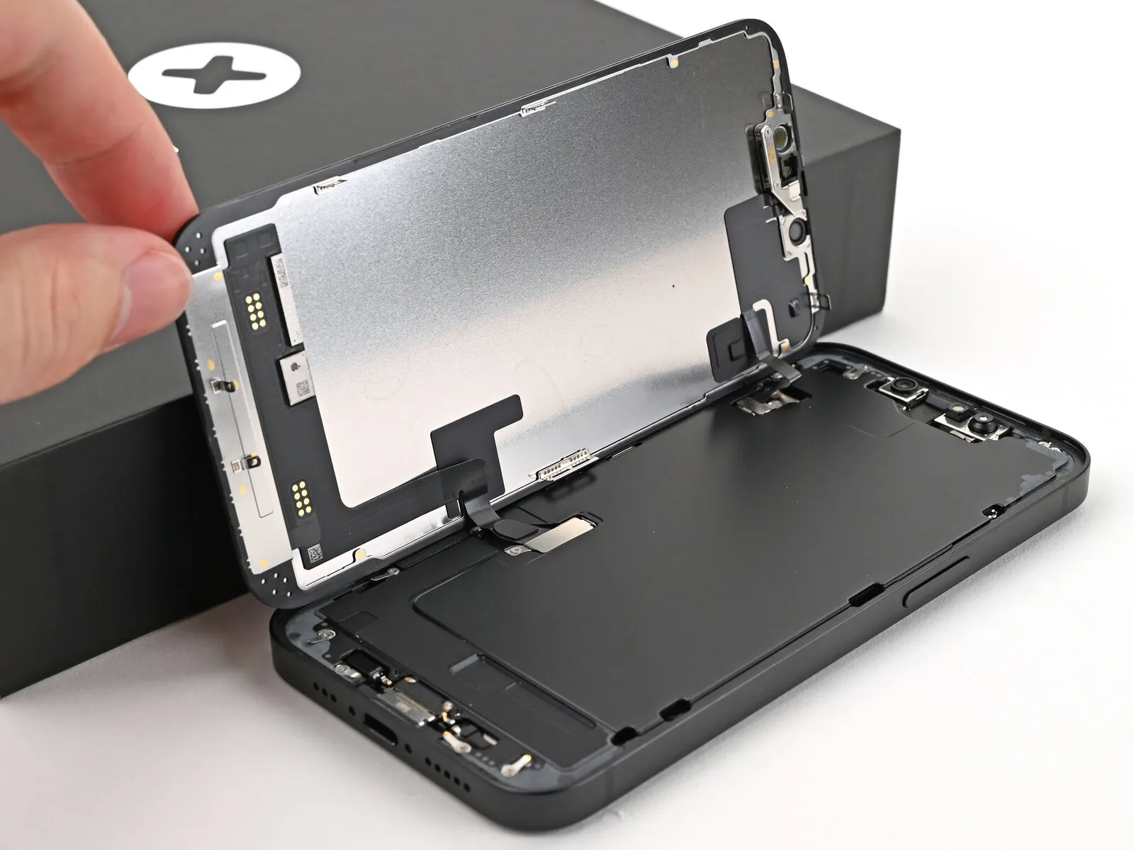
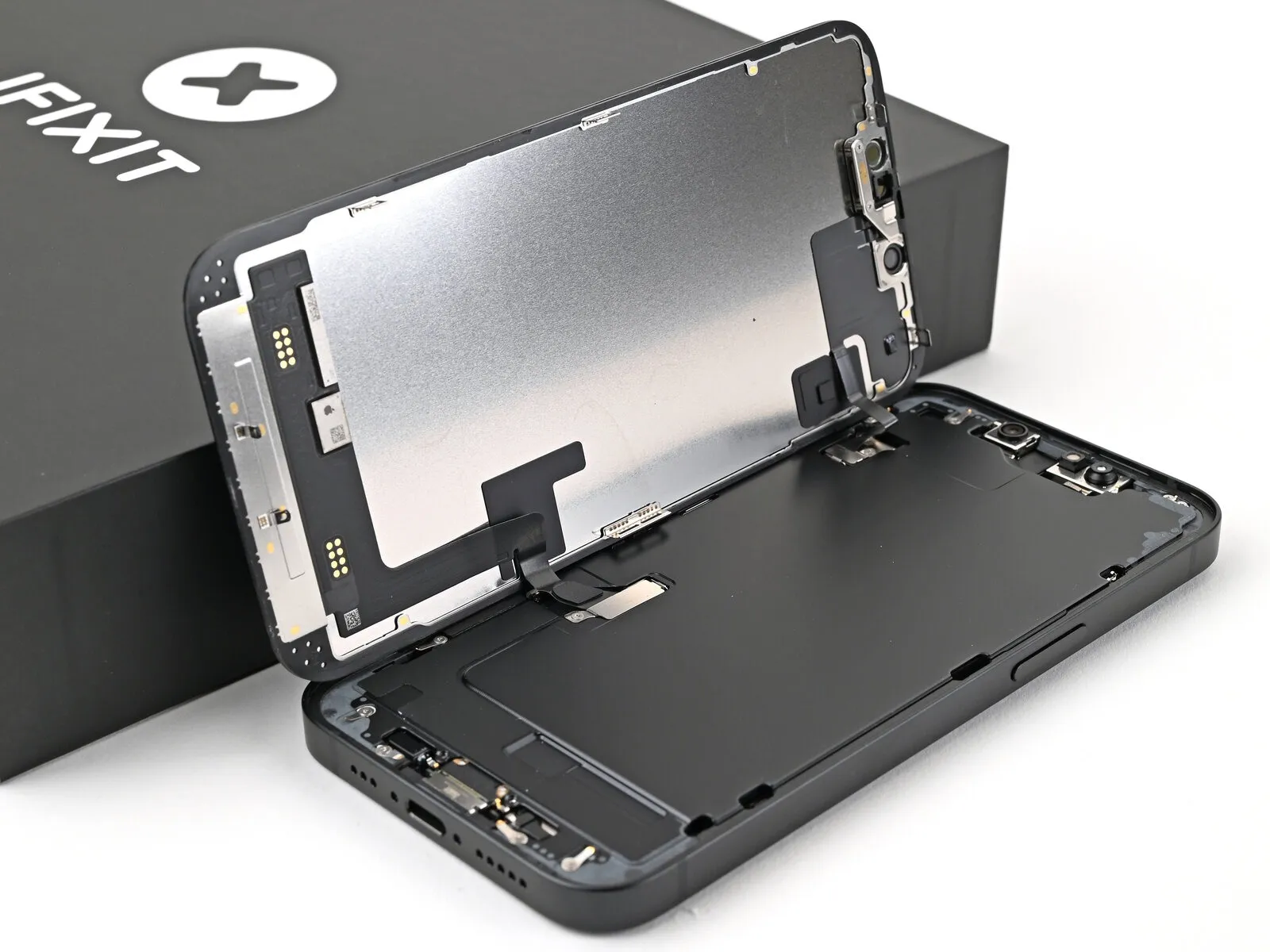
- Ensure the display panel is completely detached from the device's housing; should resistance be encountered, re-examine the surrounding edges using a prying tool to identify and release any remaining adhesive or secured fasteners.
- Carefully pivot the display assembly upwards, positioning it over the left side of the phone's body, and maintain its stability with a rigid, uncontaminated support.
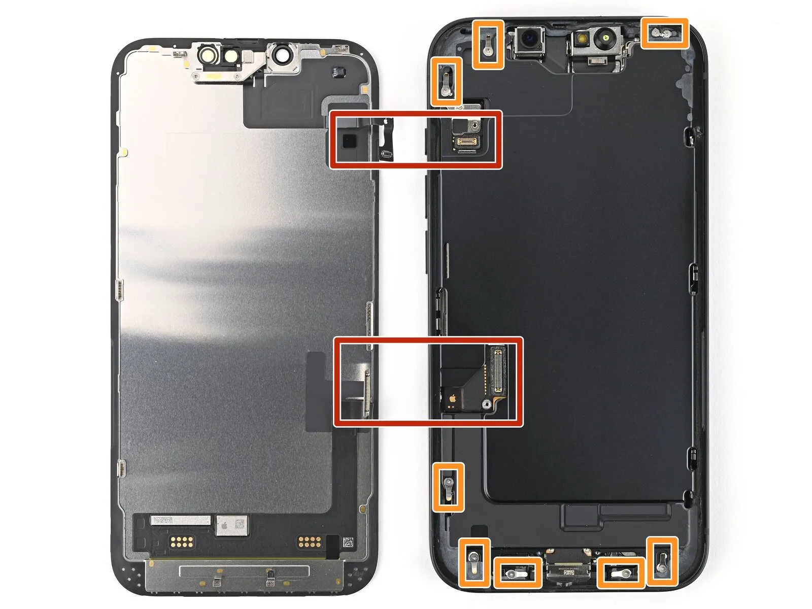
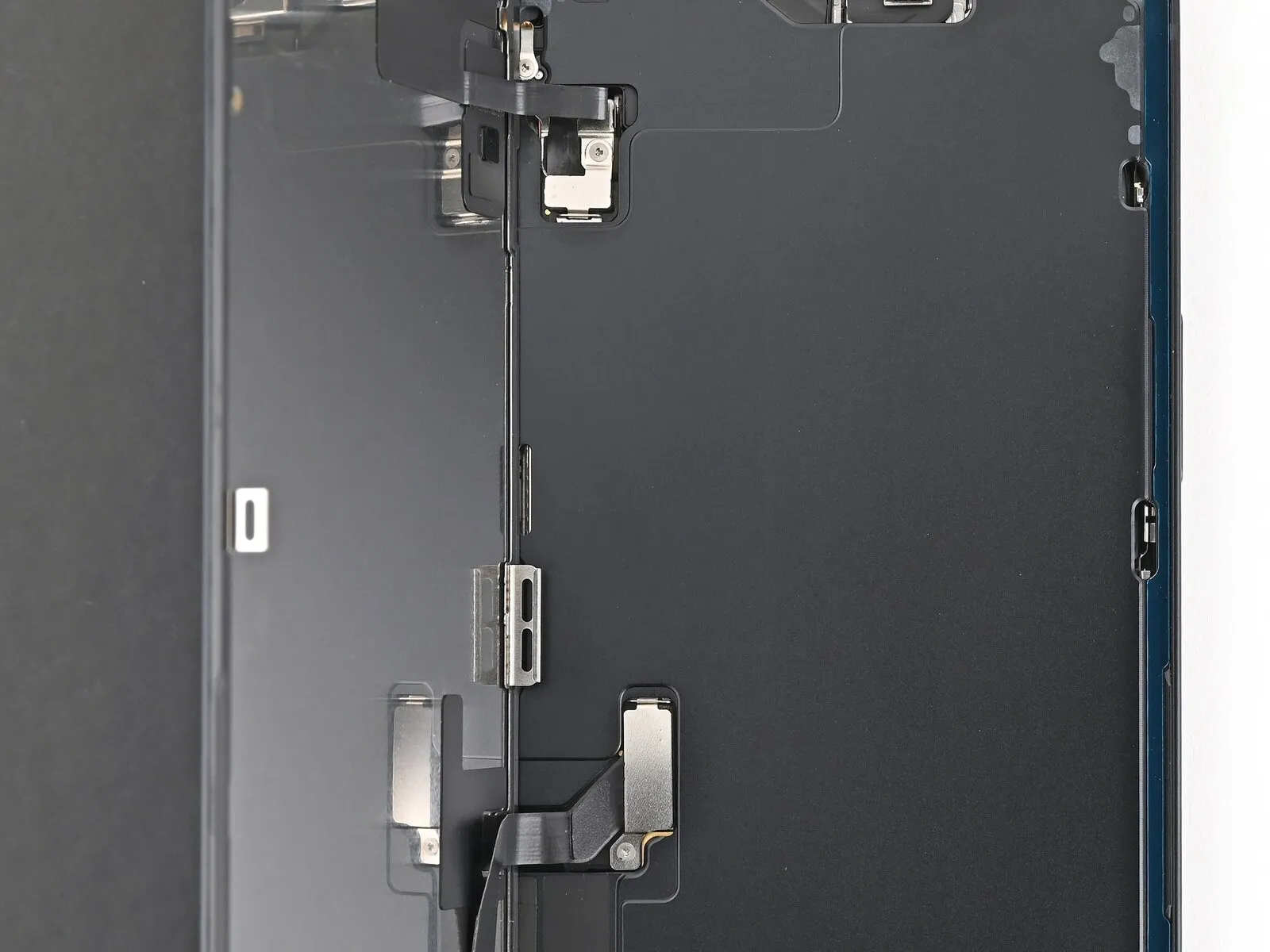
Step 16 | Remove the cover screws
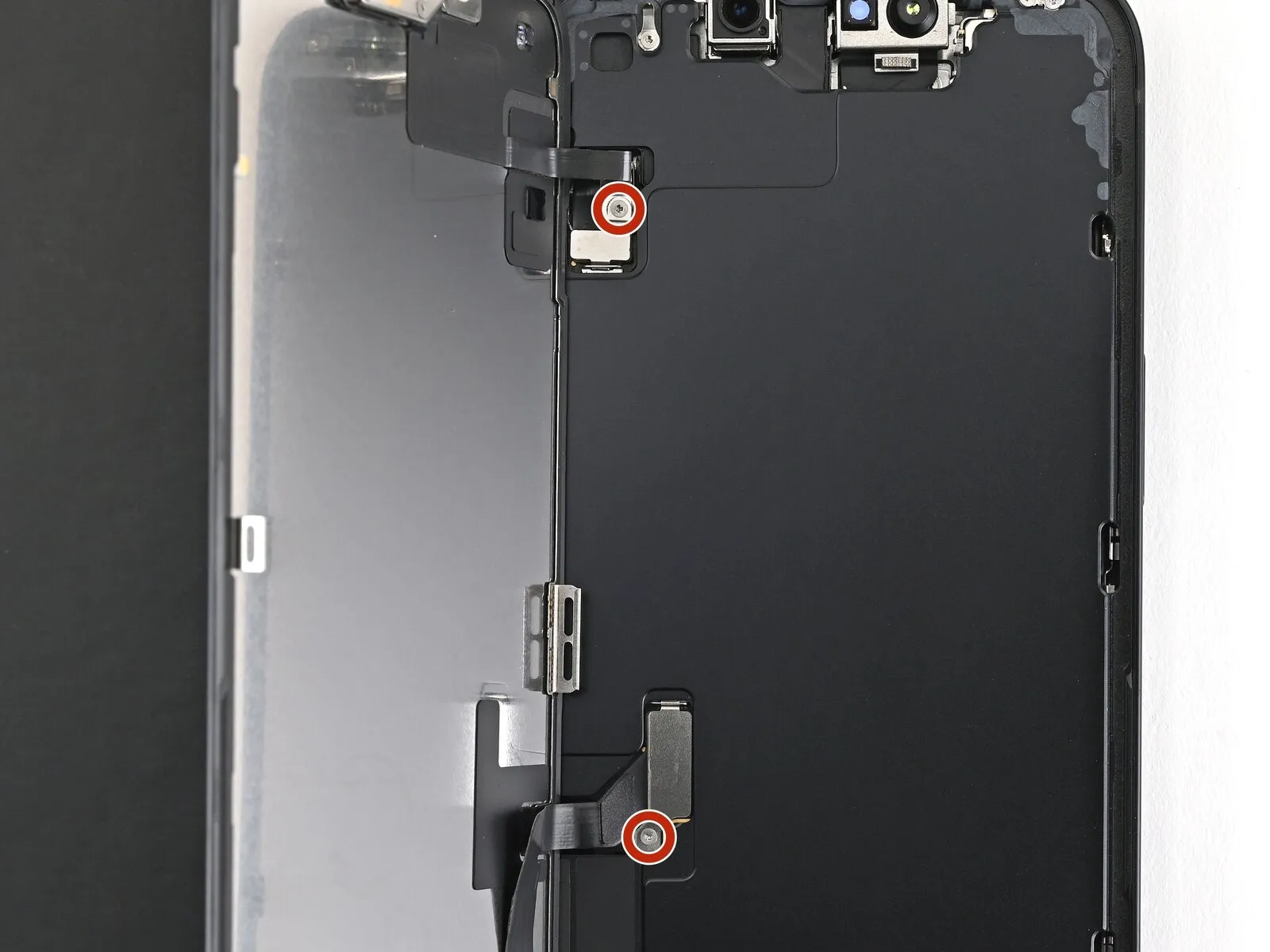
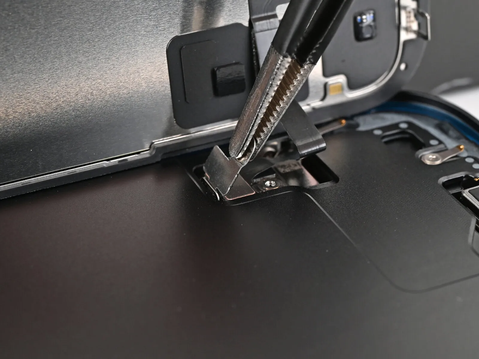
Step 17 | Remove the covers
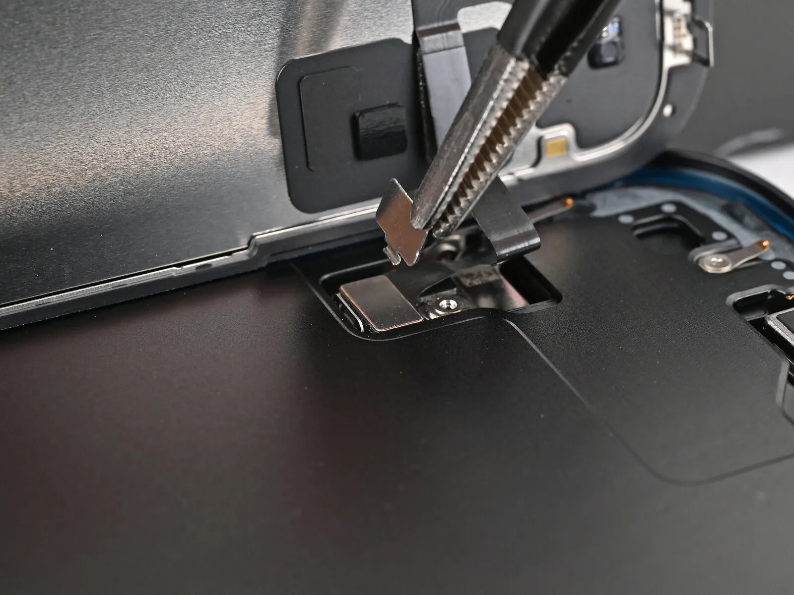
- Employing tweezers or manual dexterity, elevate the front sensor cover until it achieves a 90-degree inclination, subsequently disengaging it from the securing notch on the logic board.Carefully detach the cover from its position within the slot, ensuring complete removal.A 90-degree angular displacement is required to free the front sensor cover from its retention feature.
- The front sensor cover must be extracted from its slot after achieving the specified angular release.
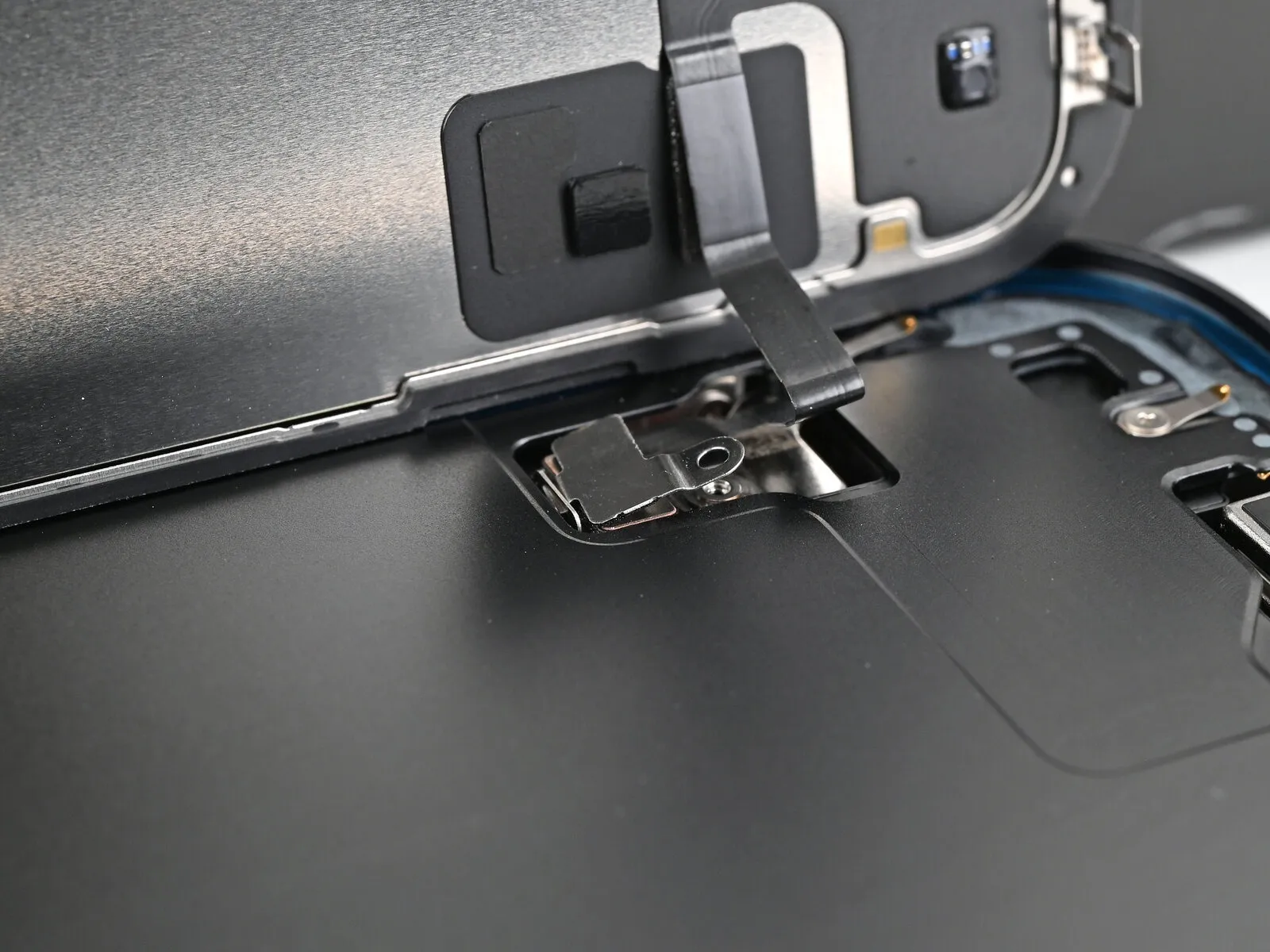
Step 18
- Employing tweezers or manual dexterity, gently raise the screen connector cover, angling it slightly to disengage it from its corresponding position within the logic board.To fully detach the cover, elevate it from its secured location on the logic board.This separation allows for the complete removal of the screen connector cover.
- Ensure the cover is entirely clear of the logic board to prevent obstruction during subsequent repair steps.
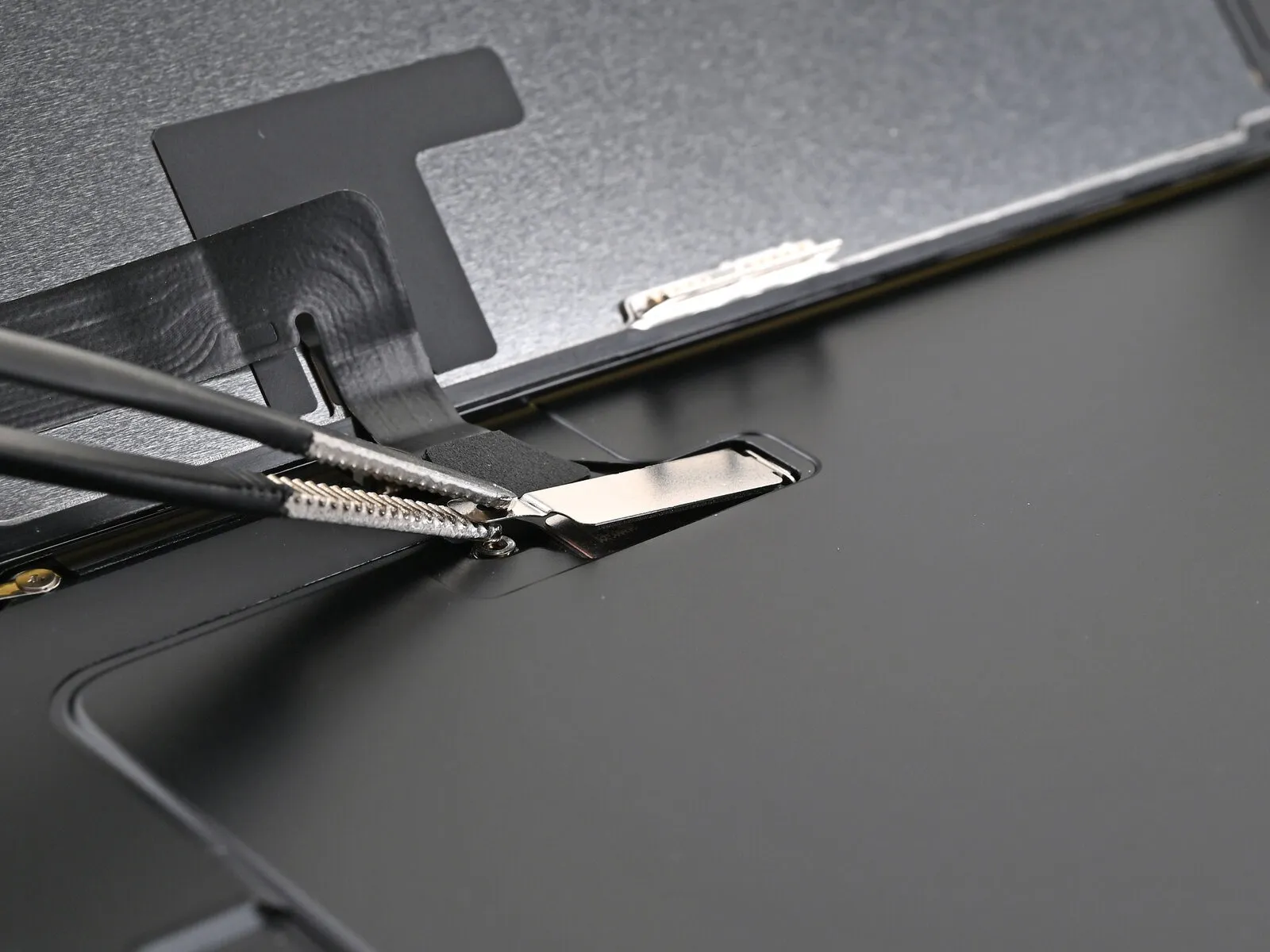
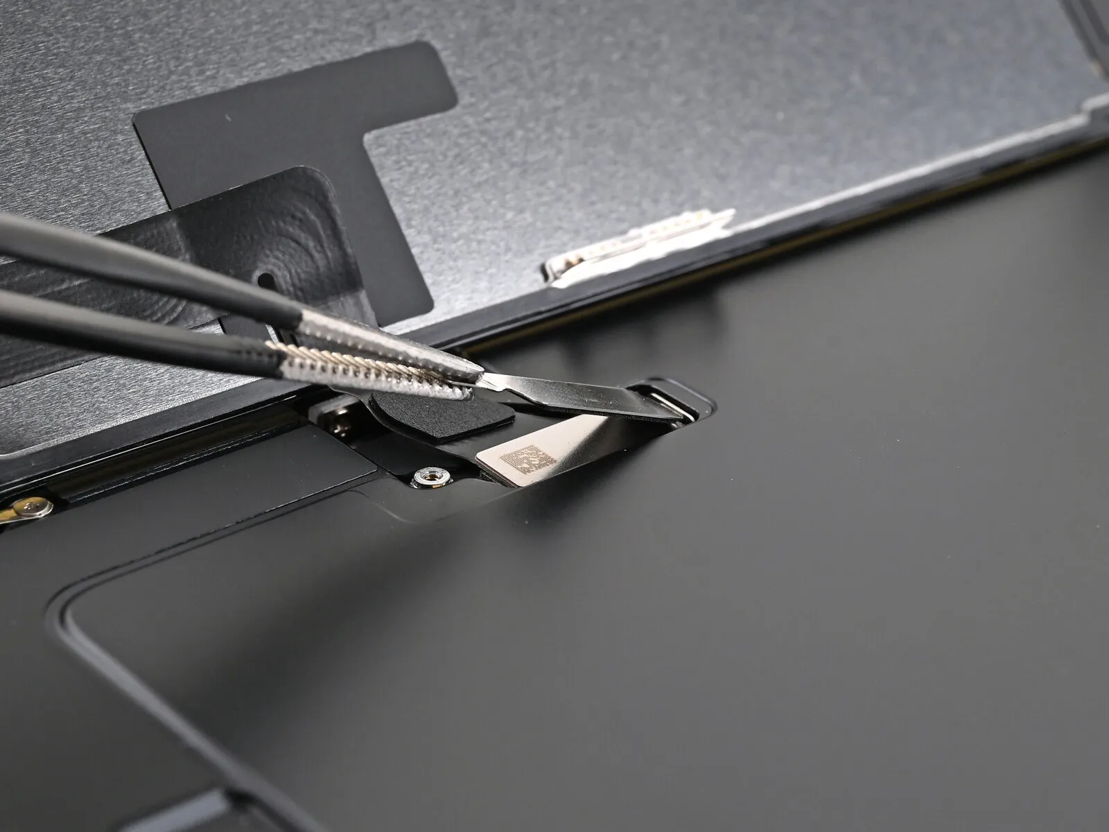
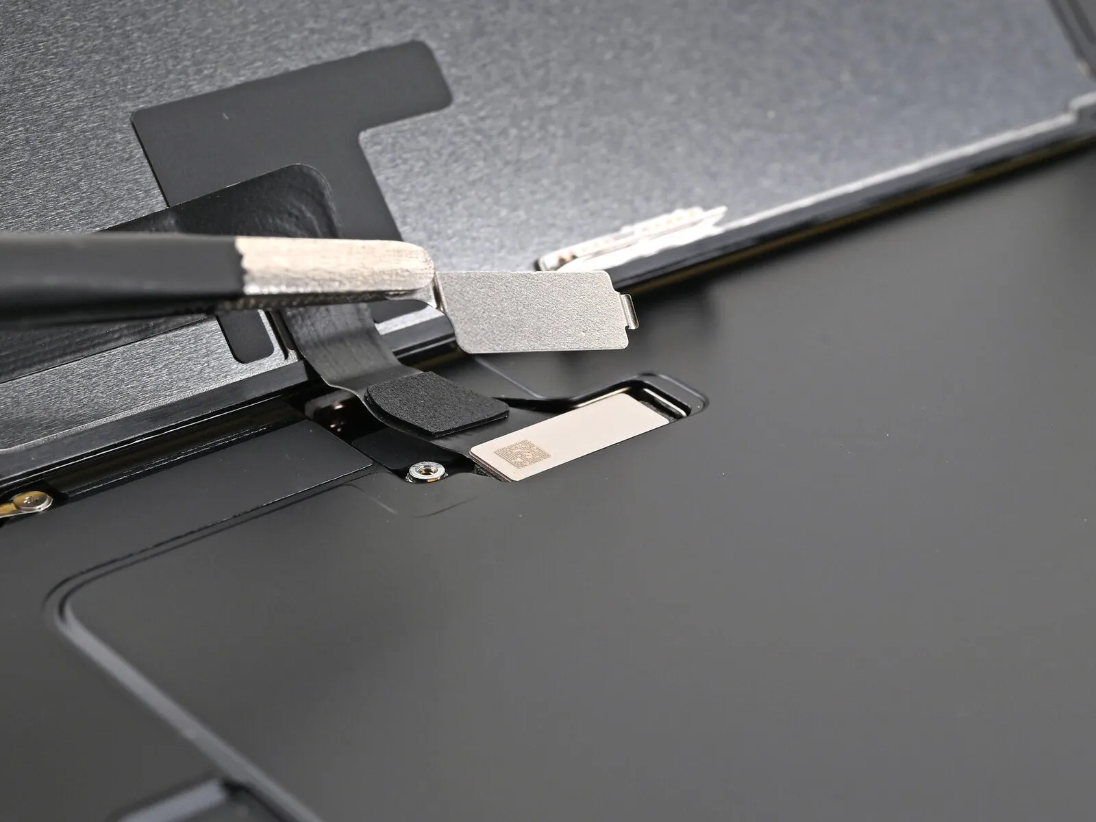
Step 19 | Disconnect the screen
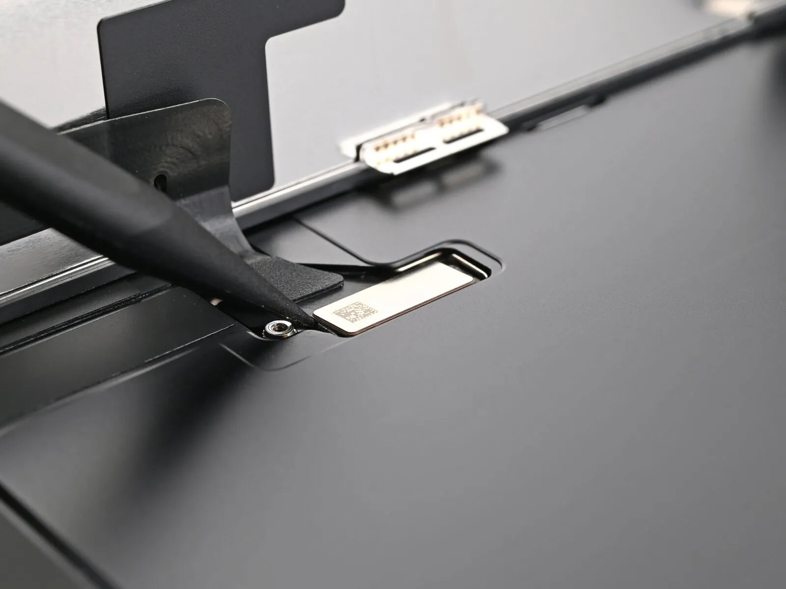
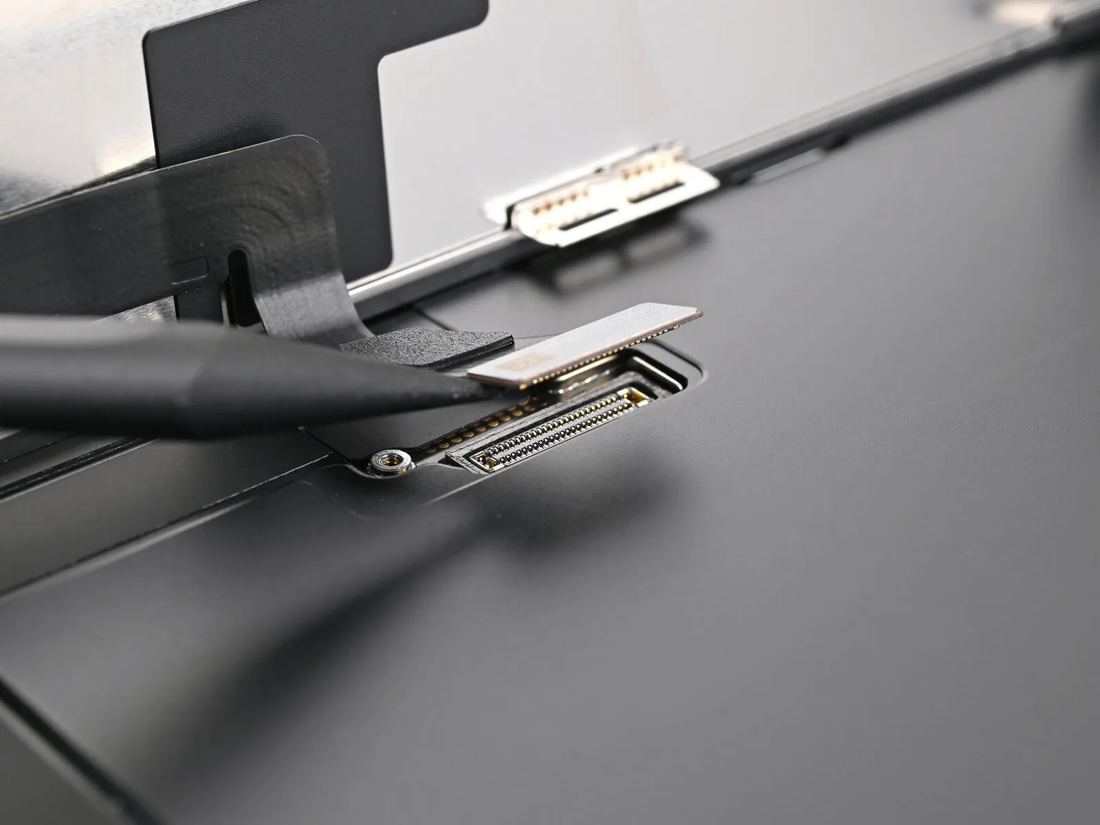
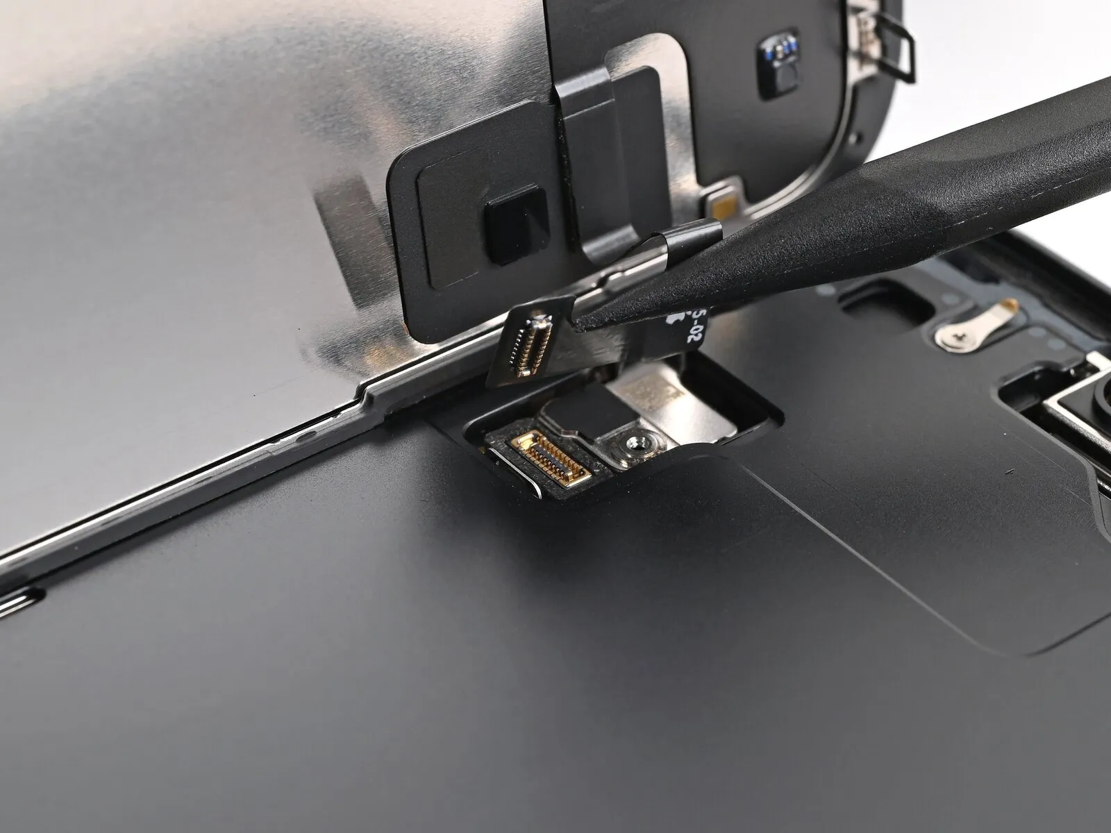
- Employ the pointed end of a spudger tool to carefully lift and detach the screen press connector.The front sensor press connector should also be separated by utilizing the same prying technique with a spudger.This disconnection process requires precision to avoid damaging adjacent components.
- Ensure the connector is fully released from its socket before proceeding with subsequent steps.
Step 20 | Remove the screen
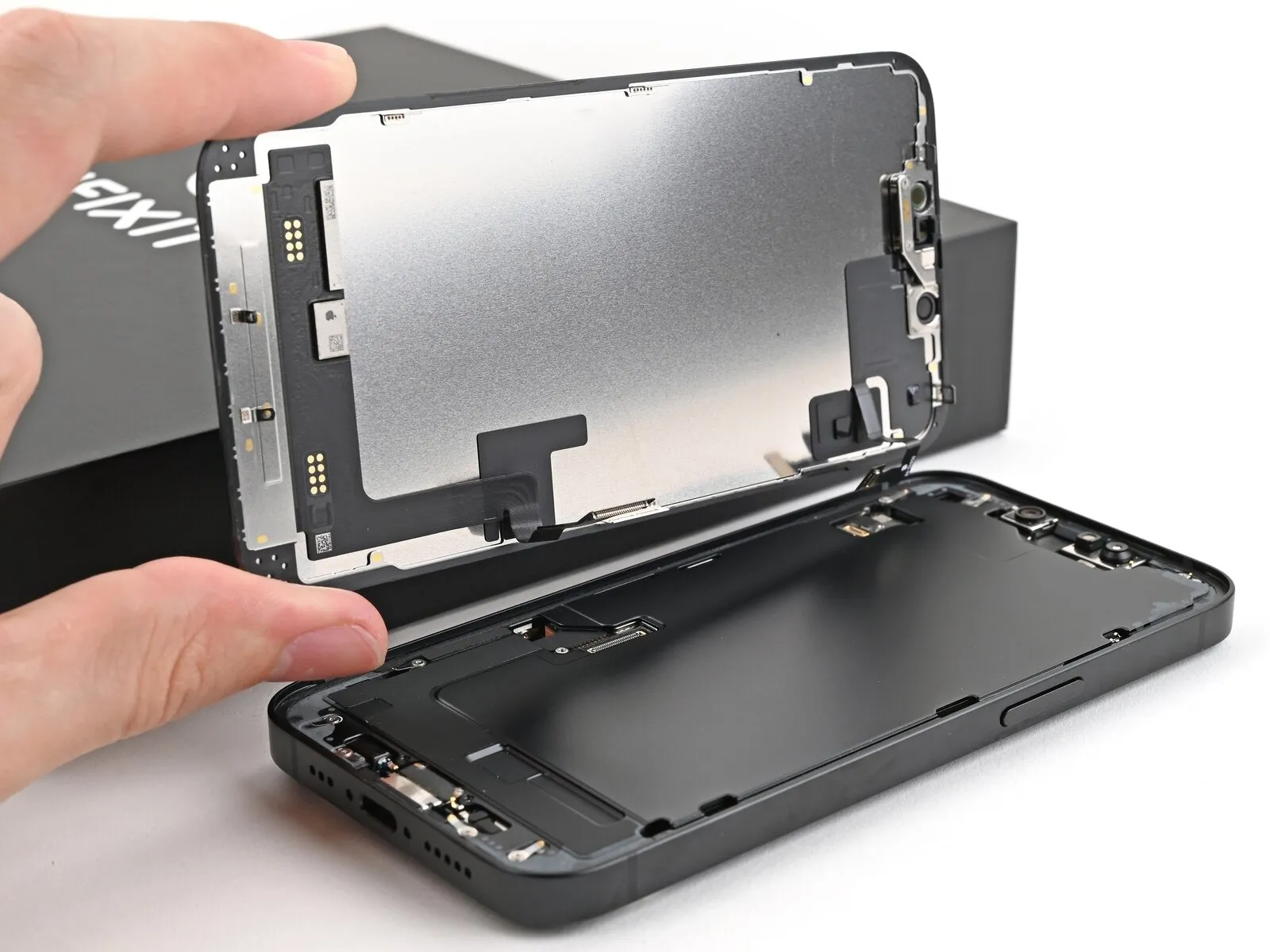
- Detach the display panel from its surrounding structural support to facilitate its removal.
Step 21 | End of disassembly

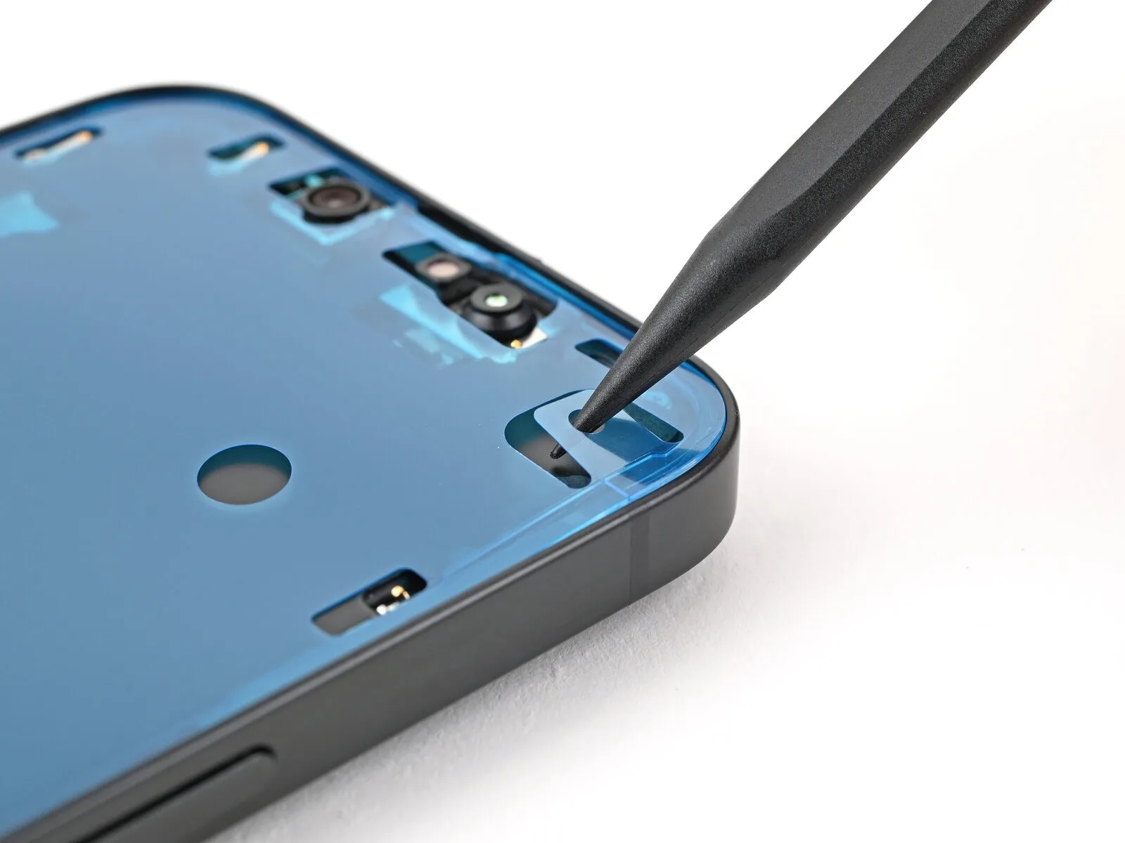
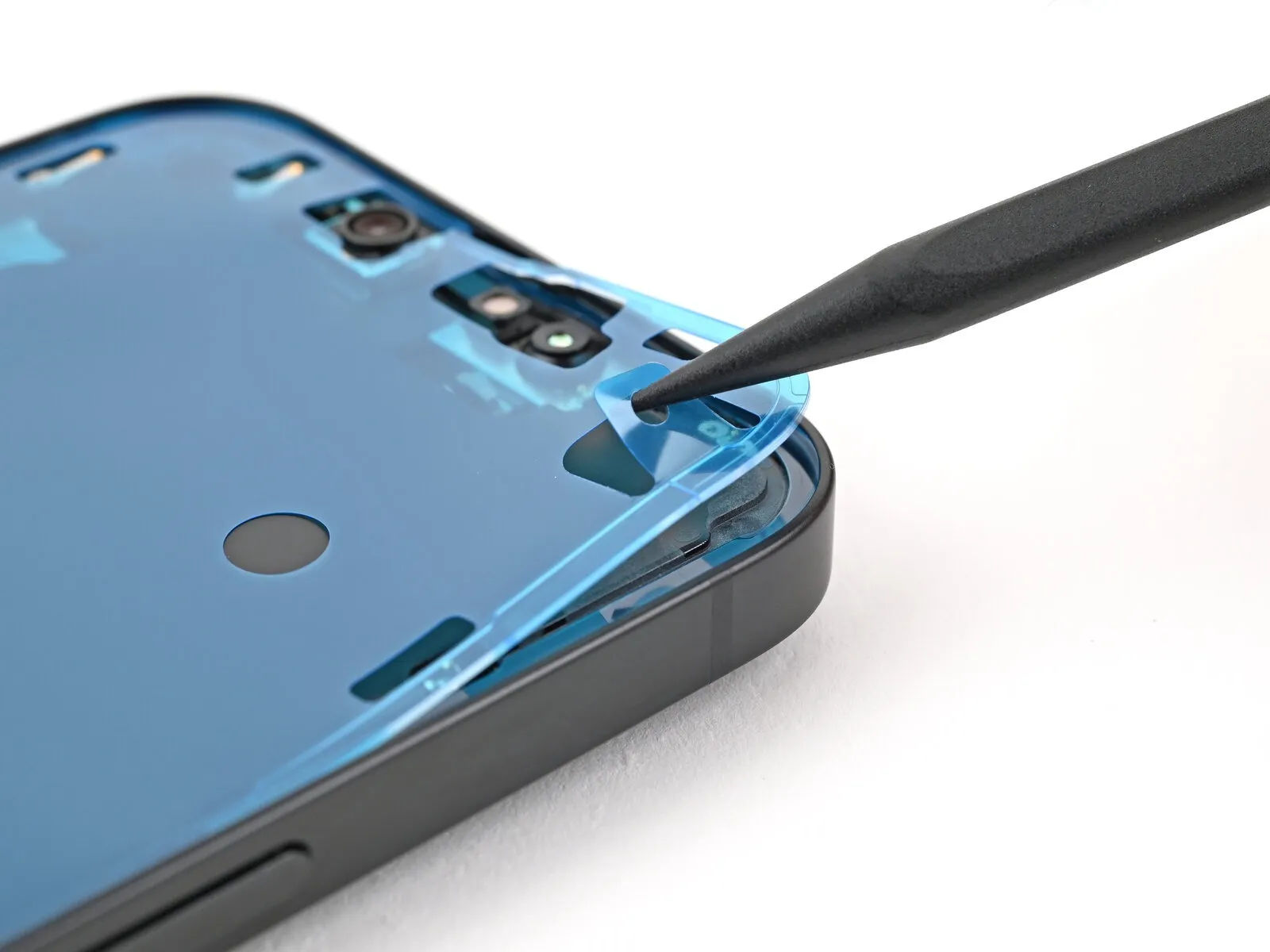
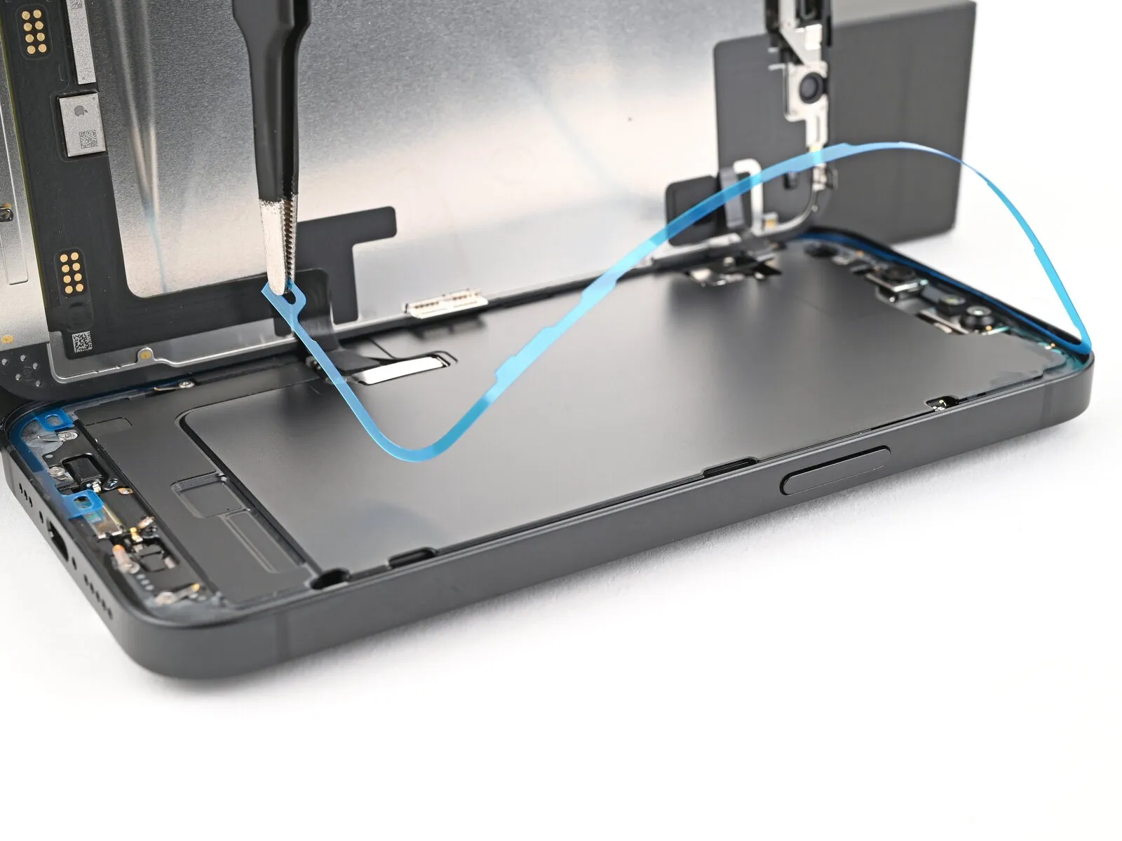
Step 22 | Remove the old adhesive
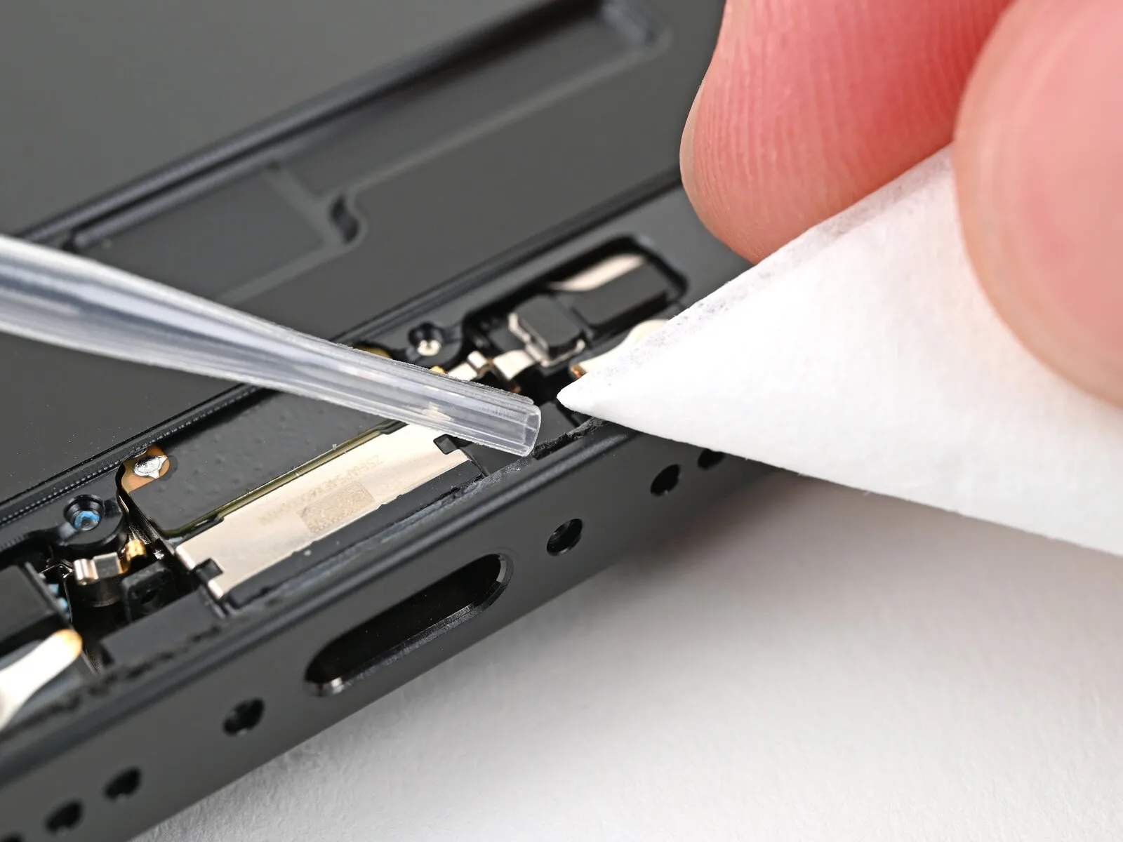
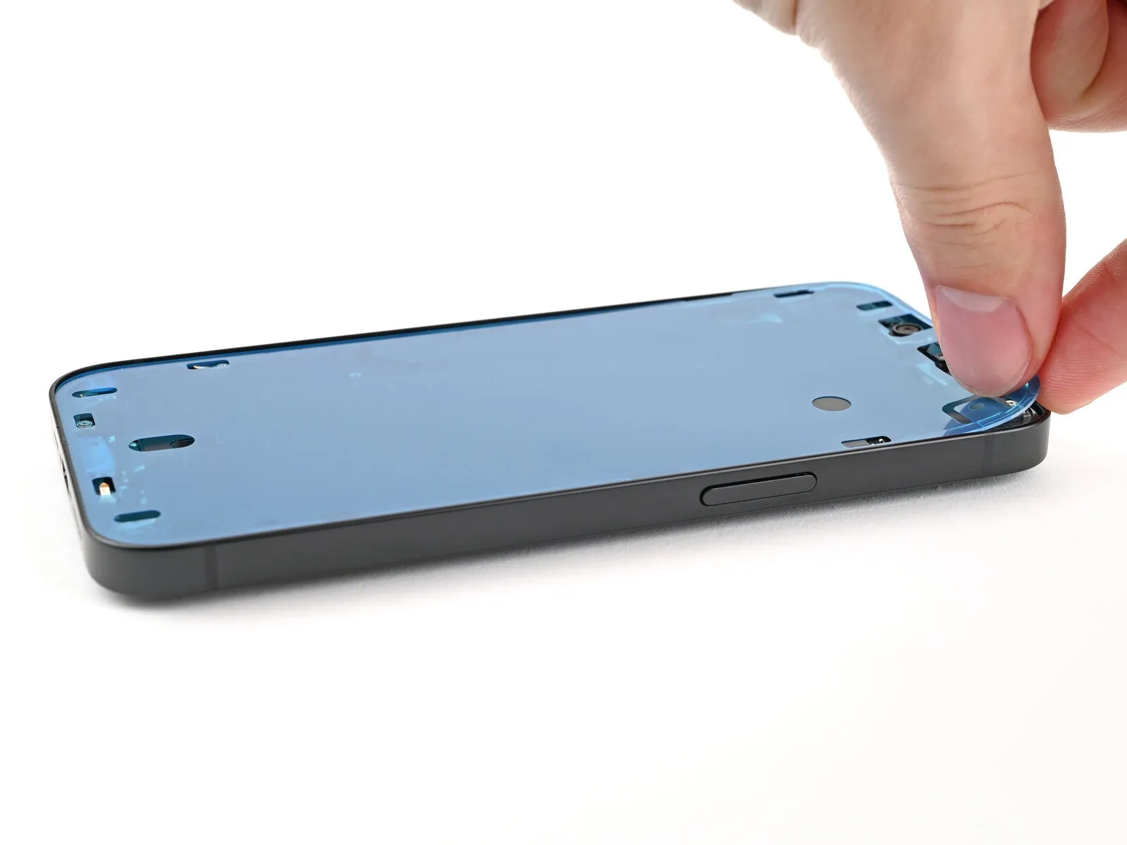
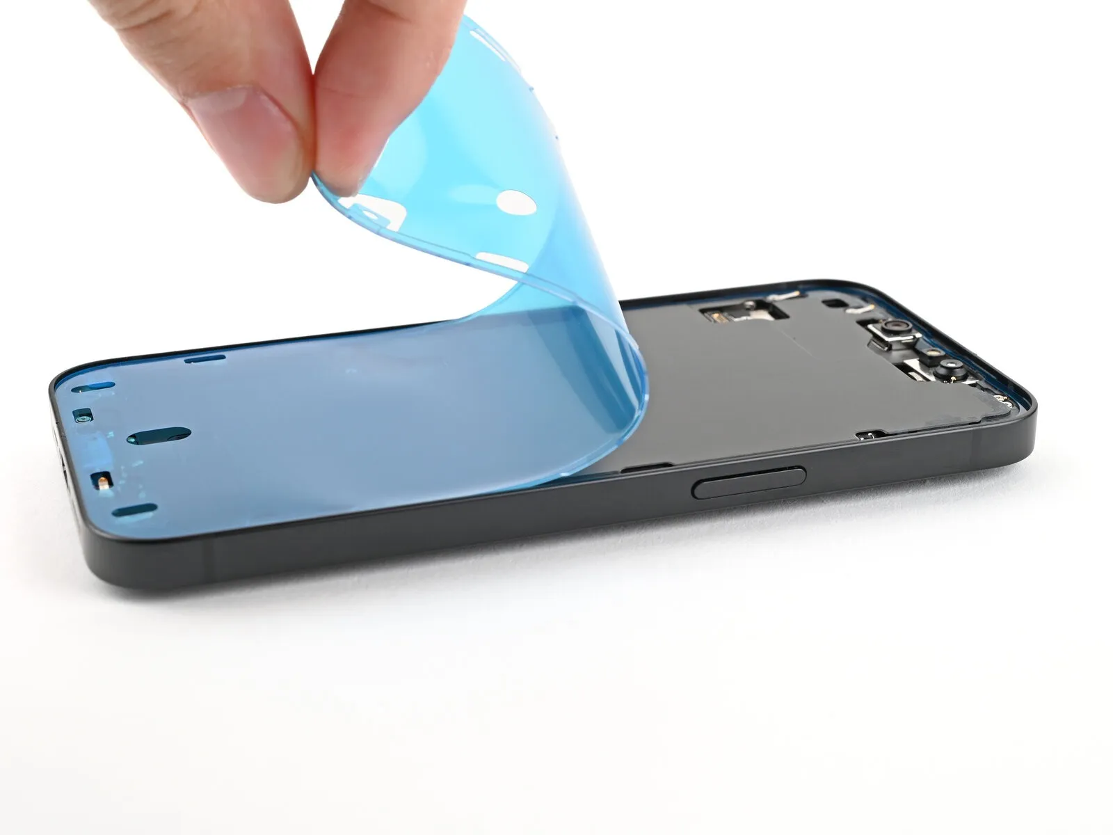
- Employing tweezers is necessary for extracting the adhesive sealant that borders the frame's edges.Prior to grasping the adhesive with tweezers, it might be required to gather it into a concentrated pile using the tip of a spudger.A spudger's pointed end can be utilized to manipulate the adhesive into a more accessible form.
- To eliminate any remaining adhesive traces, utilize a coffee filter or a lint-free cloth saturated with isopropyl alcohol exceeding a 90% concentration.Thoroughly clean the frame's surface to ensure complete removal of the adhesive residue.High-concentration isopropyl alcohol, greater than 90%, is essential for effectively dissolving the adhesive.
- Carefully maneuver the tweezers to avoid damaging the frame while removing the adhesive.
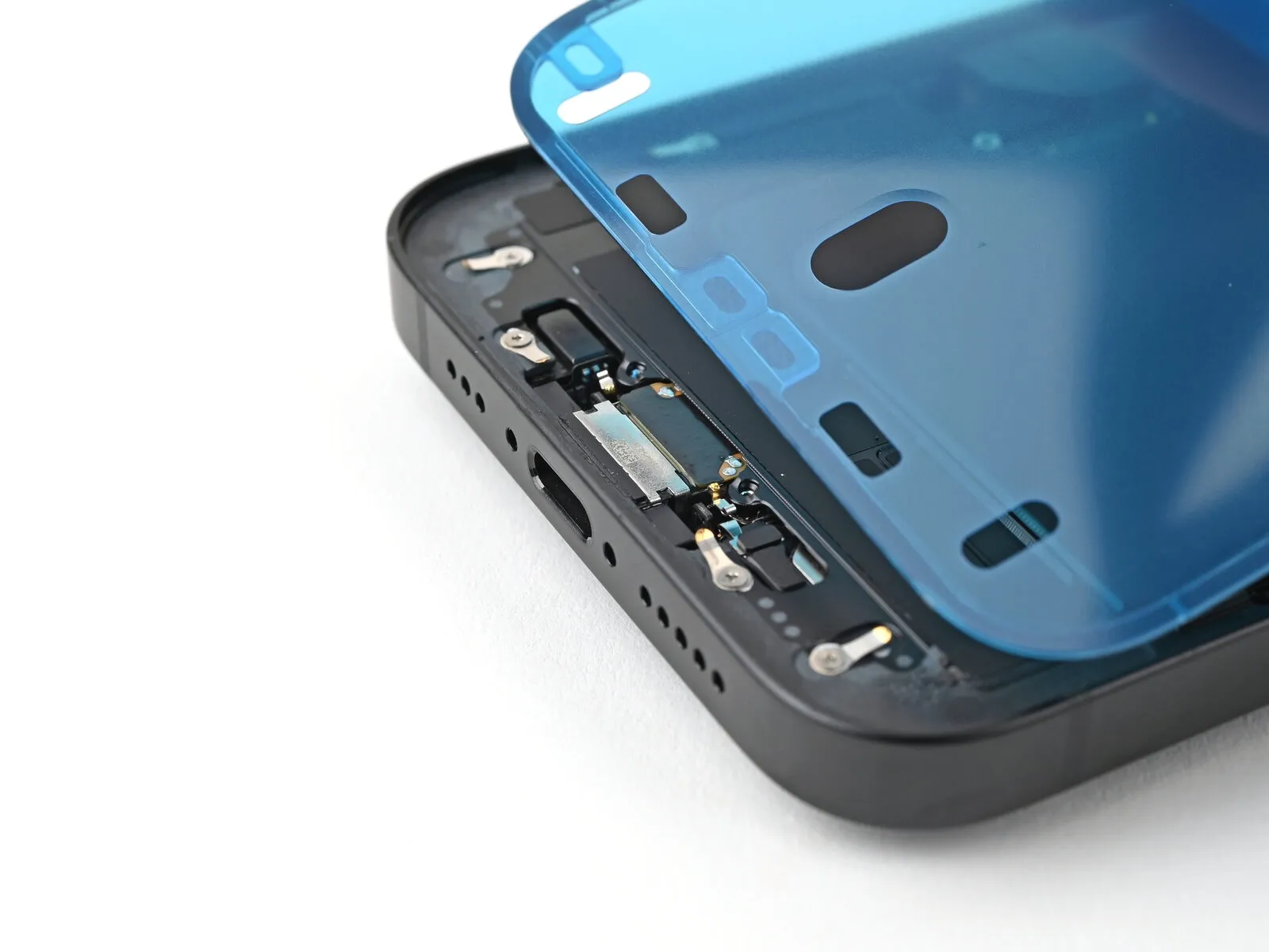
Step 23 | Orient the adhesive
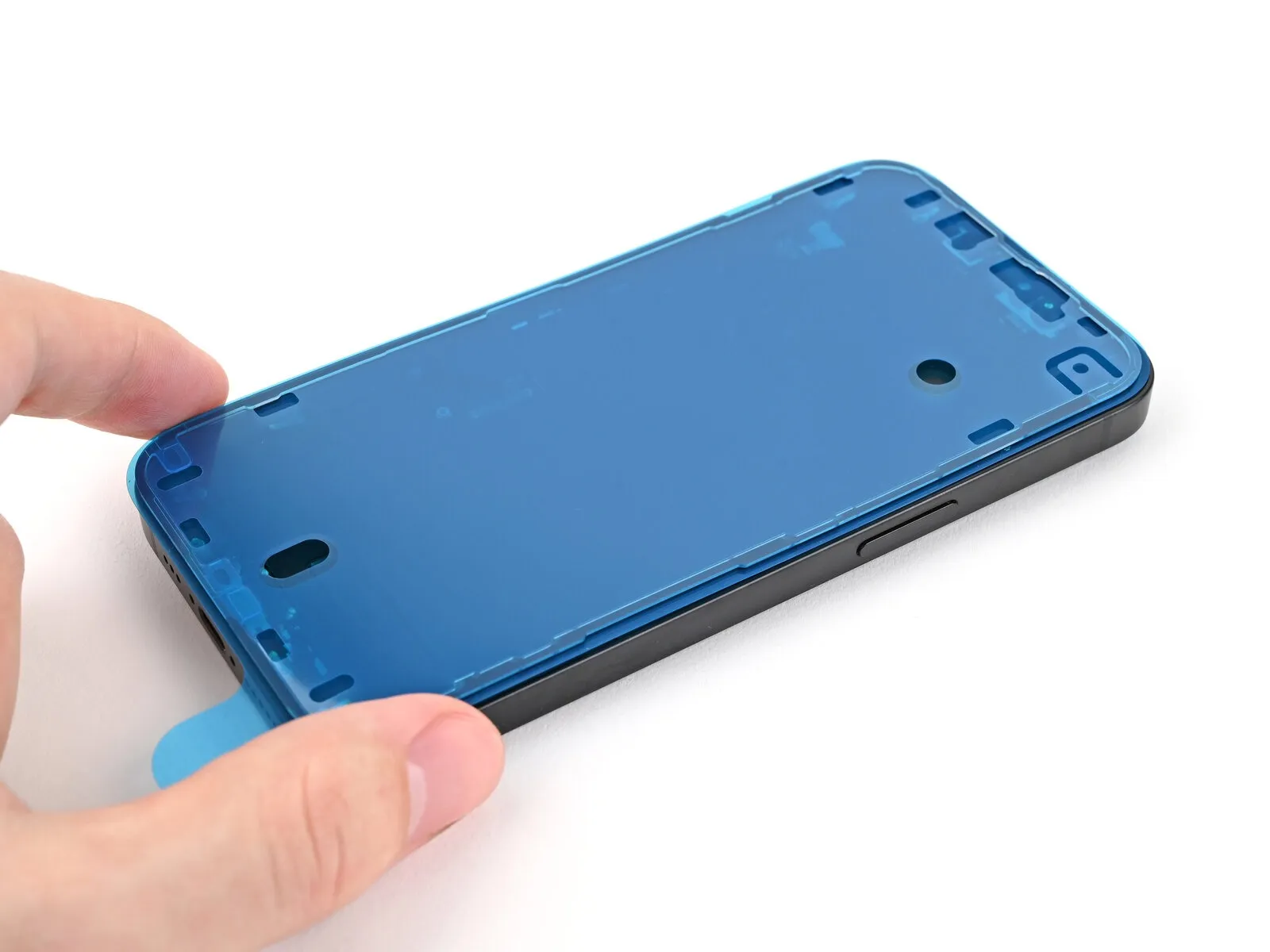
- Carefully position the adhesive over the device's surface, utilizing openings such as those for spring connectors and the front camera to confirm proper alignment.
- Variations in appearance may be observed among adhesive products.
Step 24 | Apply the adhesive
- After applying pressure to secure the adhesive, any adjustments are impossible; complete removal and replacement with fresh adhesive will be necessary.
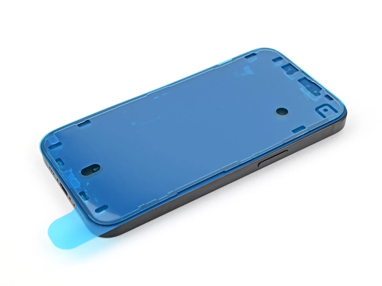
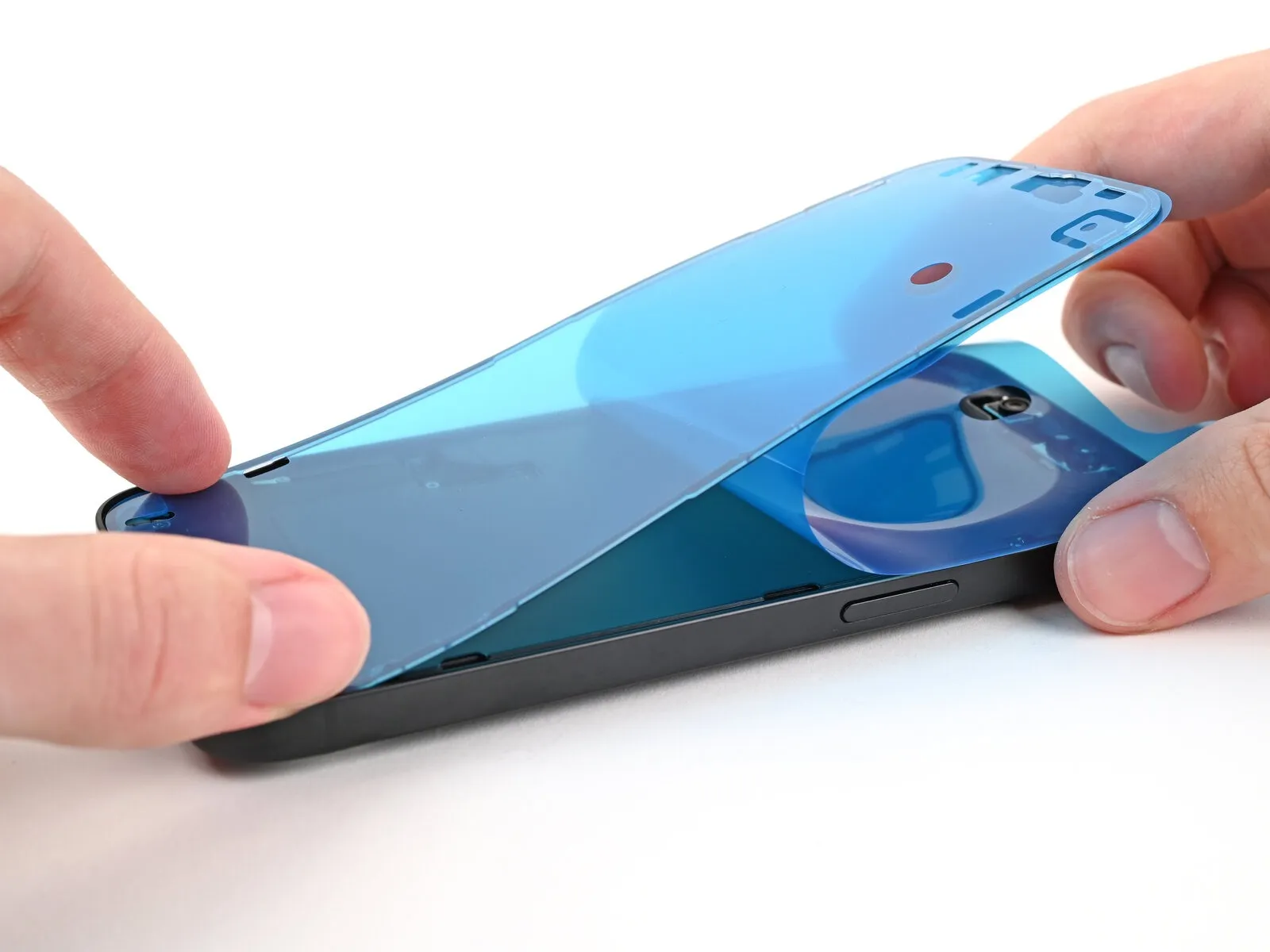
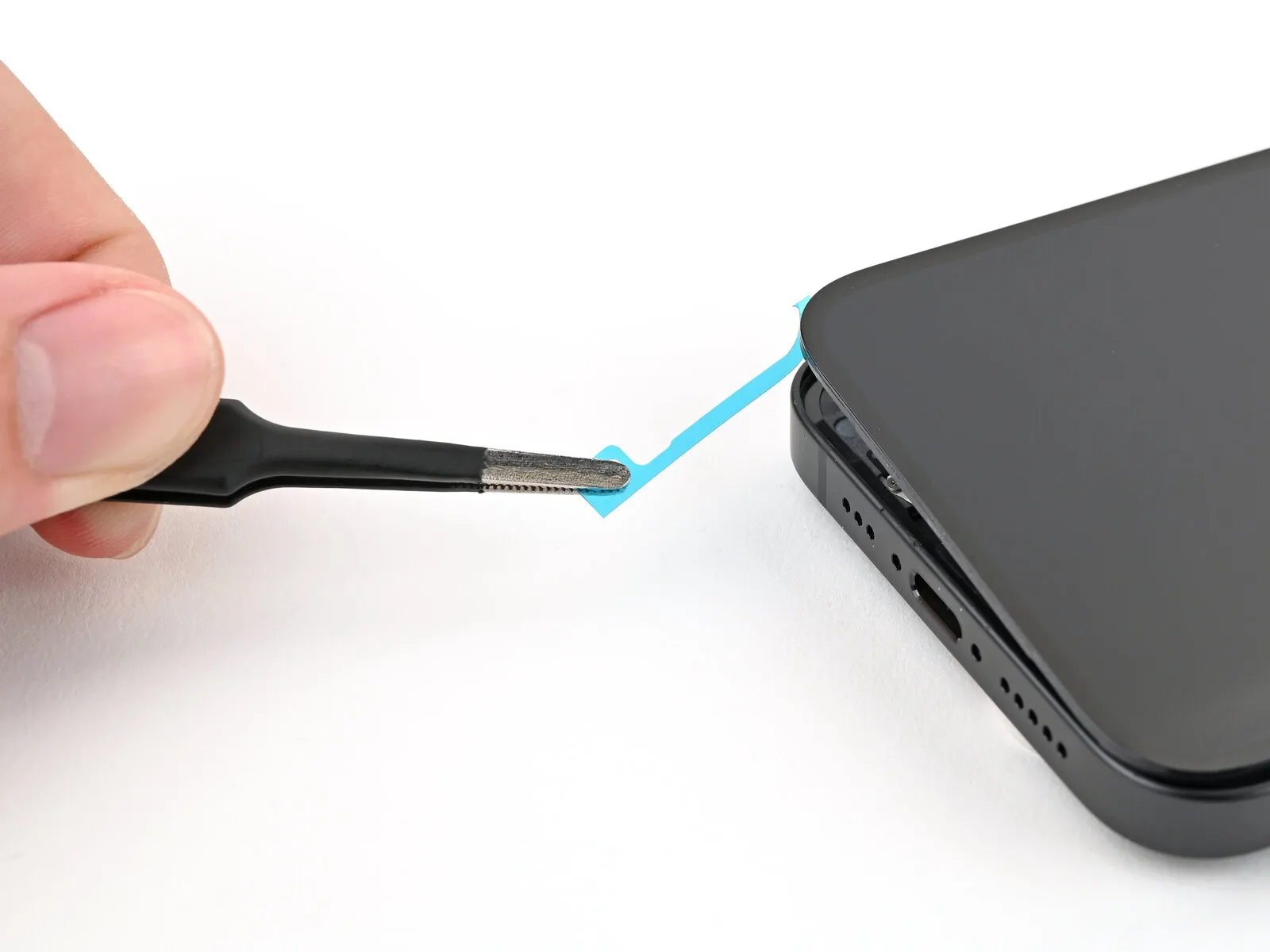
- Initiate the peeling process of the protective backing from the adhesive's surface, beginning at the lower edge using the provided pull tab, but avoid complete removal of the backing.
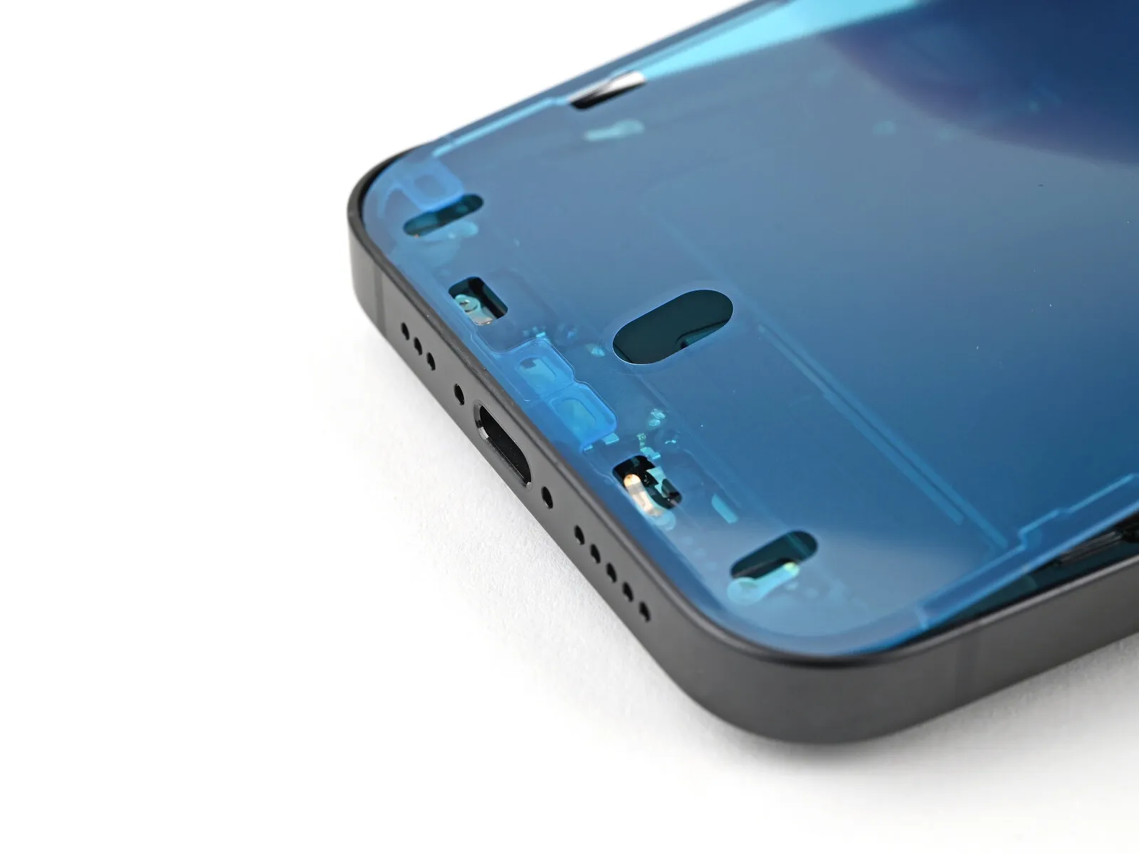
- Maintain the blue liner away from the work area while carefully positioning the adhesive so that it aligns precisely with the lower boundary of the iPhone.
- Ensure proper contact between the adhesive's lower edge and its designated cavity within the frame, verifying that the iPhone’s spring contacts correspond with the liner’s openings.
Step 25
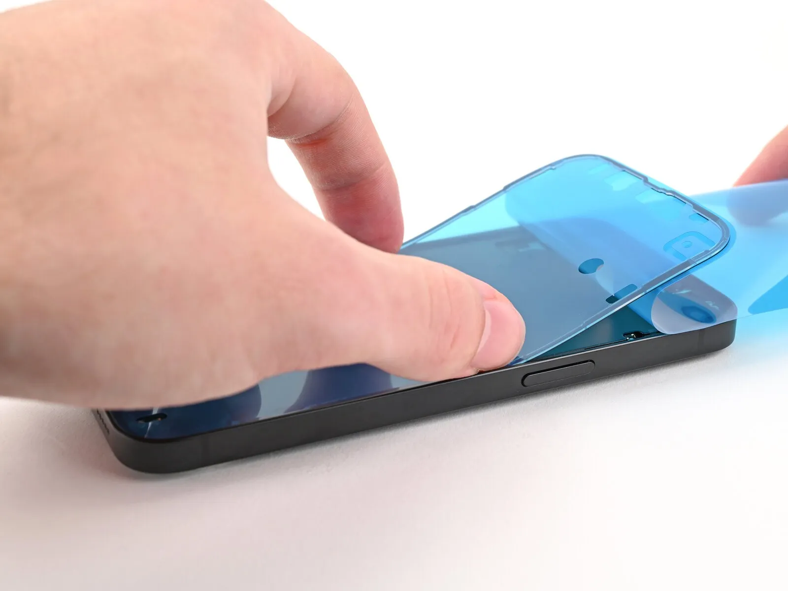
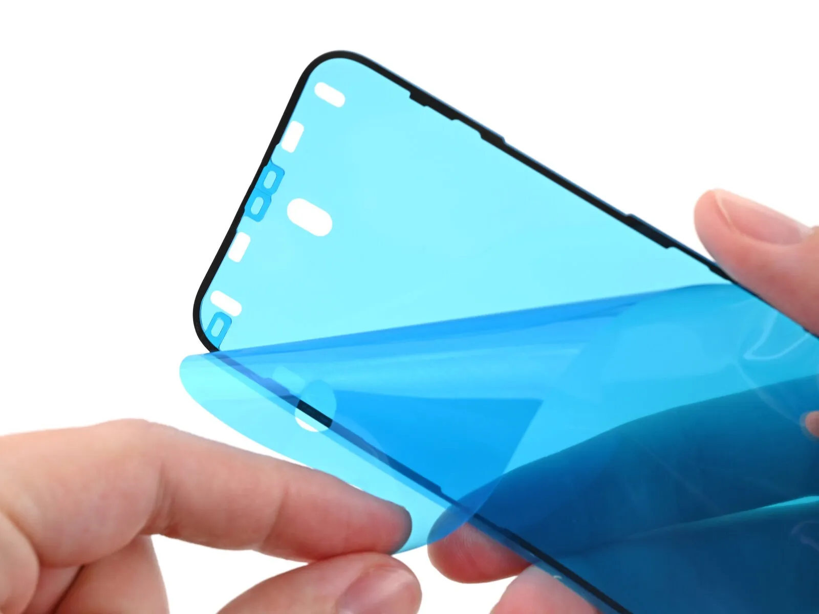
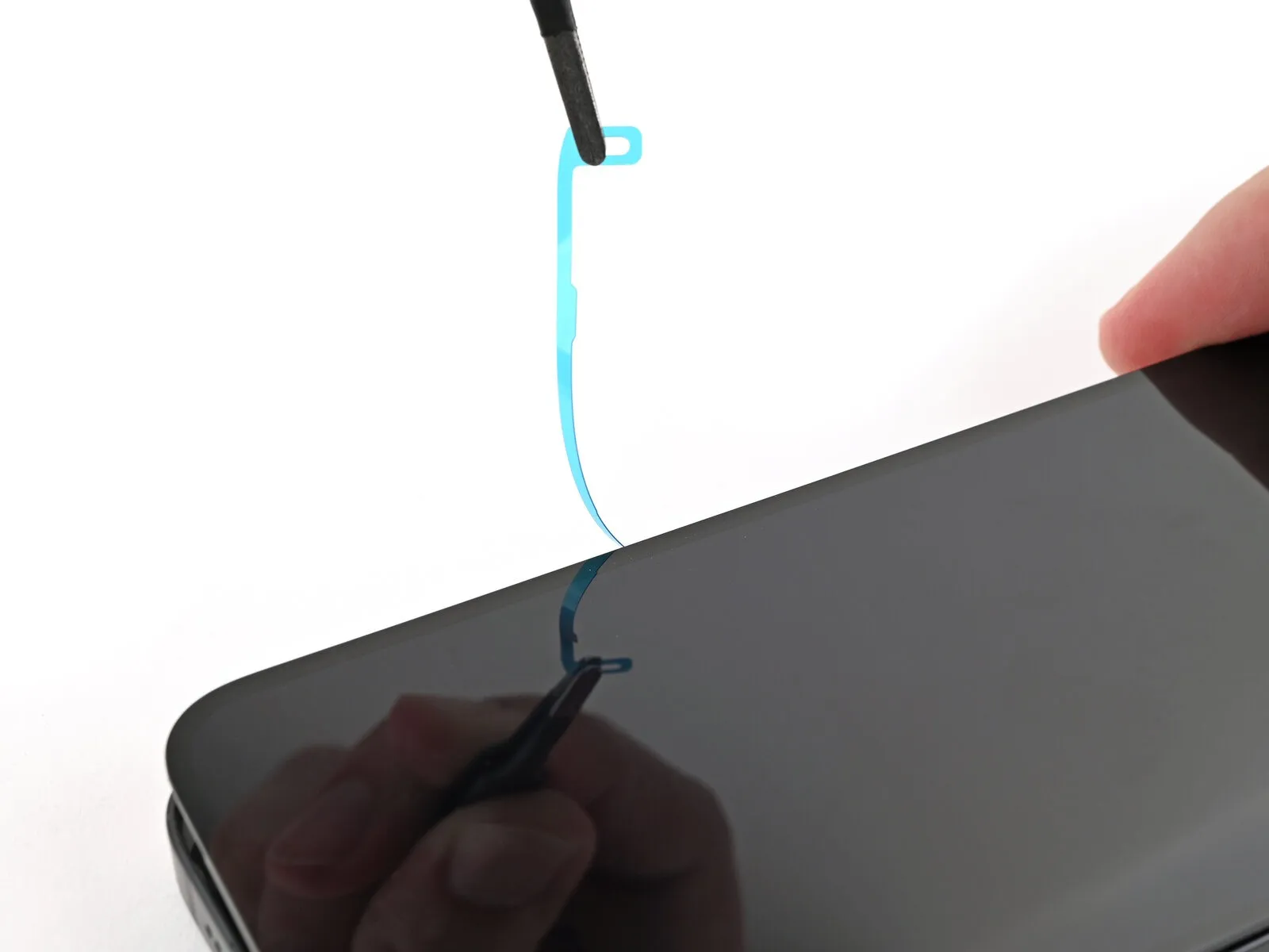
- Progressively remove the protective backing from the adhesive strip, ensuring firm contact with the iPhone's perimeter during application.
- Proper alignment of the adhesive's lower edge should result in automatic positioning of the side and top edges; if misalignment occurs, discard the adhesive and repeat the process with a fresh strip.
- Should a misaligned adhesive strip be encountered without a replacement available, the iPhone can be reassembled and used temporarily without adhesive; however, be aware that the device's water resistance will be diminished until replacement adhesive is applied.
Step 26 | Press the adhesive into place
Step 27
Step 28
Step 29 | Connect the screen
- Carefully position the display assembly against the left side of the iPhone’s frame, ensuring stability with a rigid support like a specialized opening tool or a similar object.Establish an electrical connection between the display and the device’s logic board by gently pressing on the screen press connector with the broad, blunt tip of a spudger or a fingertip.
- Replicate the previous connection procedure for the front sensor press connector, ensuring a secure electrical link.
- Maintaining consistent pressure and alignment, proceed with the connection process to avoid damage to the delicate components.
Step 30
Position the screen connector cover's upper edge into the corresponding recess on the frame, subsequently applying pressure via the press connector.
Step 31
Position the front sensor connector cover to achieve a ninety-degree angle.Guide the cover into its designated slot within the frame.Ensure the cover is oriented correctly during insertion.The connector cover should be placed precisely to facilitate proper alignment.
Apply pressure to the cover to secure its connection to the press connector.
Step 32 | Install the cover screws
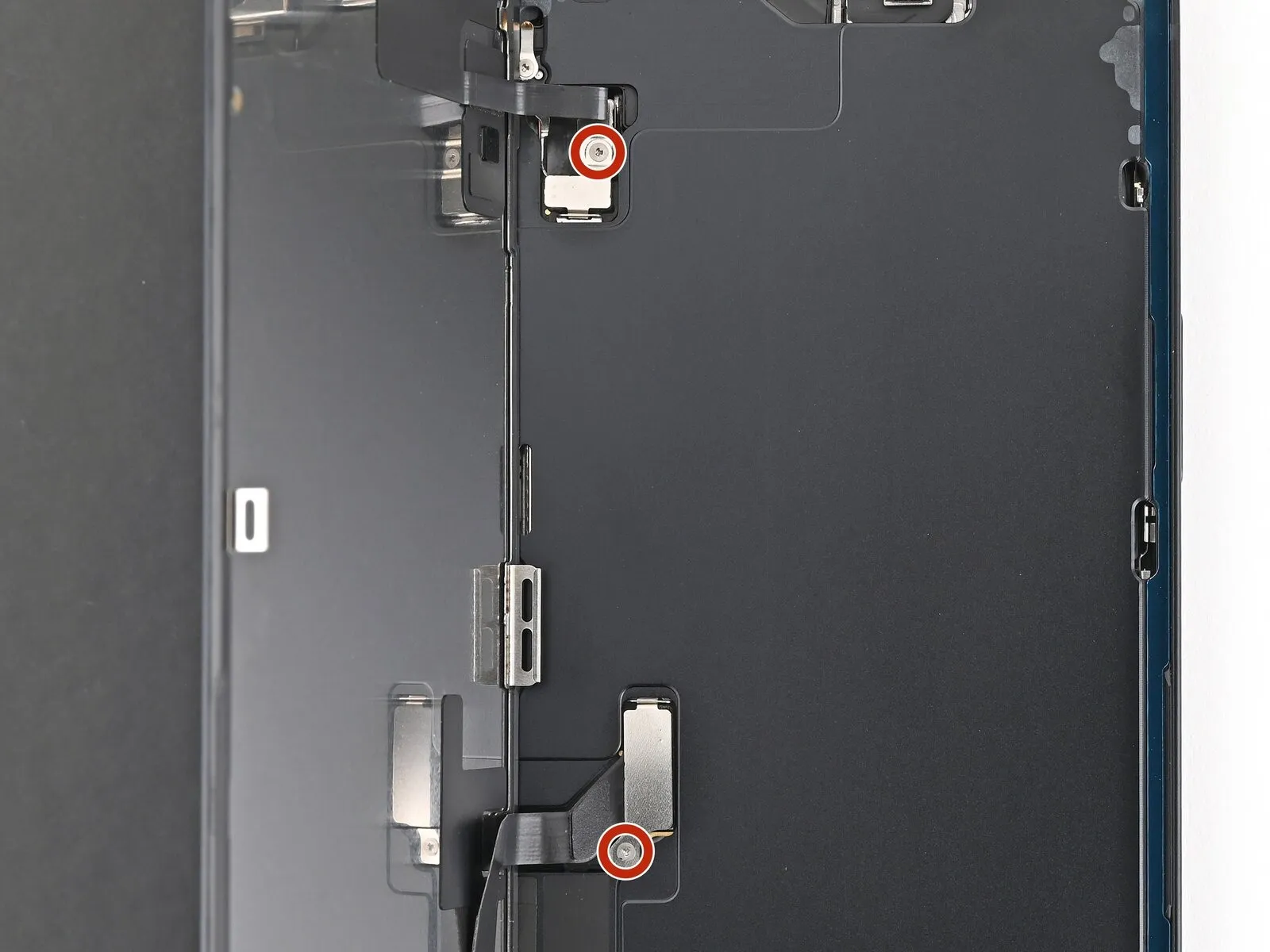
Employ a specialized tri-point screwdriver, specifically a Y000 type, for the installation process.The screws, each measuring 0.9 millimeters in length, are utilized for fastening.These fasteners specifically secure the protective covers positioned over the front sensor connector.Additionally, the screws also secure the protective cover for the screen connector.
Step 33
Employing tweezers or direct finger manipulation, secure the blue pull tab to detach the liner from the right-hand side.Ensure the display surface remains free from adhesive contact during manipulation.Position the screen assembly above the device's body, maintaining separation from the adhesive.Proceed to extract the remaining two liner sections.The use of tweezers facilitates a precise grip on the blue pull tab.
- Manual finger contact can also be utilized to achieve the same result of liner removal.
Step 34 | Place the screen
Position the display assembly over the device's chassis, ensuring its edges match the surrounding structure.Carefully align the display's perimeter with the phone's frame to guarantee proper seating.Maintain visual confirmation of the screen's placement relative to the phone's borders during installation.
Step 35
Position the display panel flat against the device's frame, applying pressure to ensure the retaining clips securely interlock.To guarantee complete engagement of all fastening clips, apply even pressure across the entire edge of the screen.The screen's proper alignment with the frame is confirmed when the clips audibly click into their locked positions.
- Consistent pressure around the screen's boundary is essential for achieving a secure and uniform connection with the frame's clips.
Step 36 | Heat the screen
- Additional techniques for screen stabilization are detailed in the subsequent steps, if clamps are not utilized.
Step 37 | Press the screen


- Utilize the iPhone's original packaging lid, positioning it on a level work area if available.
- Should the original box not be accessible, proceed to an alternative technique.
- Position the iPhone, with the display facing upwards, within the box lid, ensuring the camera bump aligns with the designated cavity.
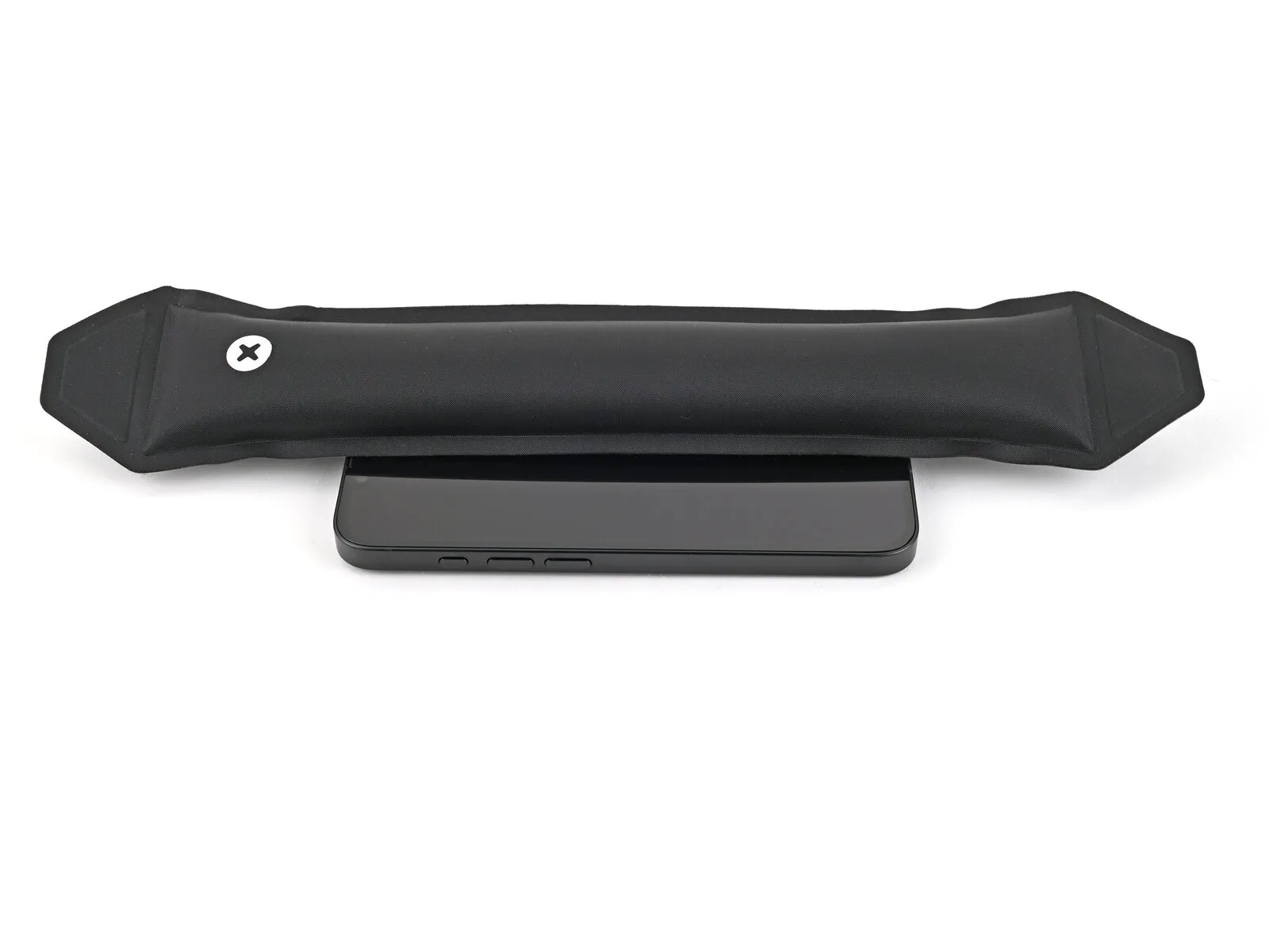
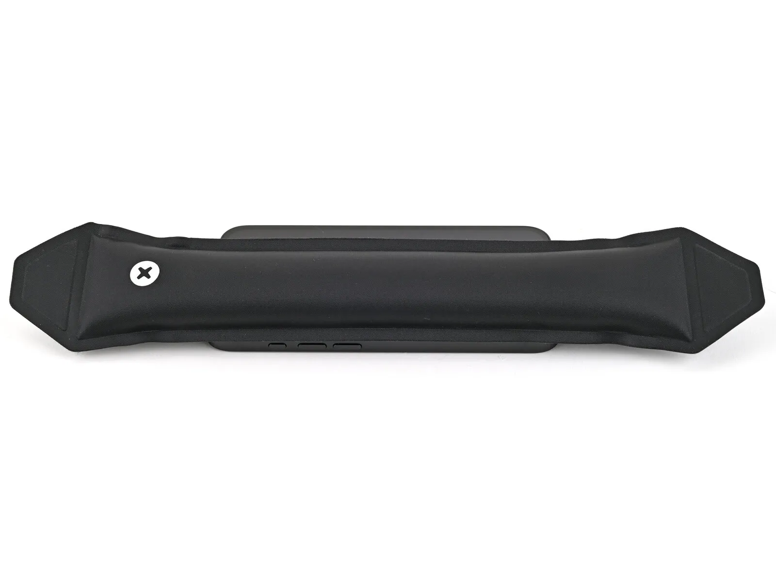
- Employ an object with a height exceeding the box's sidewalls but approximating the iPhone's width; then, place this object atop the iPhone, followed by several substantial weights.
- Allow the applied pressure to remain constant for a minimum of thirty minutes; reduce this duration proportionally to the weights' mass, with overnight stabilization being optimal.
Step 38


- Position the iPhone with the screen facing downwards upon a cushioned, level plane.
- Secure the rear glass with adhesive tape to safeguard its surface coating.
Step 39


- Ensure uniform dispersion of the coins and confirm their collective thickness is equivalent to or greater than the height of the camera module's protrusion.
Step 40

- Maintain the applied pressure for a minimum of thirty minutes; extend this duration proportionally to the objects' reduced weight, with an overnight period being the optimal timeframe.
Step 41 | Install the pentalobe screws
- Utilize a P2 Pentalobe screwdriver to proceed with the following steps.
- Secure the two screws, each measuring 7.8 millimeters in length, to the left and right of the charging port.These fasteners are specifically designed for this application and require the appropriate tool for installation.Proper alignment and torque are essential to prevent damage to the surrounding components during screw installation.