iPhone 17e Rear Camera Assembly Replacement
This document details the process for substituting the rear camera module within an iPhone 17e.
Image and video capture exhibiting blurriness, excessive audio interference, or difficulty achieving focus may indicate a need for camera replacement.Acquiring fresh rear glass adhesive is essential to complete this repair successfully.Visual elements within the accompanying illustrations originate from a different iPhone model, potentially showing minor aesthetic variations that do not impact the repair steps.To ensure proper sealing and structural integrity, the application of replacement back glass adhesive is crucial during reassembly.The photographic representations provided are sourced from a variant iPhone model, and may present subtle visual differences.
- Discrepancies in appearance between the guide's images and your device are expected and will not alter the repair's execution.A degraded or damaged rear camera assembly can result in compromised image quality and autofocus performance.Addressing these image quality issues often requires the substitution of the rear camera module.
Careful adherence to the outlined steps is vital for a successful rear camera replacement on the iPhone 17e.
Step 1 | Before you begin


- Initiate a power-down sequence by concurrently depressing the power button and one of the volume buttons, subsequently sliding to achieve phone deactivation.
- A fully charged lithium-ion battery presents a safety concern; therefore, depletion below 25% is mandatory before repair work begins.
Step 2 | Tape over any cracks


- A sufficiently sized, uninterrupted section of the lower edge is required to allow for secure attachment of a suction cup.
Step 3 | Remove the pentalobe screws


Step 4 | Mark your opening picks


- Using a measuring tool, determine a distance of3 millimetersfrom the pick's distal end and clearly indicate this measurement with a durable, permanent marker.
- For enhanced precision, consider marking the pick's other edges with varying measurement values.
- As an alternative method, affix a coin to the pick's tip, positioning it3 millimetersfrom the distal end.
Step 5 | Heat the bottom edge

- To initiate separation, utilize a heated iOpener against the lower perimeter of the rear glass panel, maintaining contact for a duration of 90 seconds.As an alternative method, a hair dryer or heat gun can be employed to warm the lower edge of the back glass until it reaches a palpable temperature.Exercise care to prevent excessive heat exposure, as the internal battery is susceptible to thermal degradation.
- The application of heat should be carefully monitored to avoid damage to the battery's sensitive components.
- Prolonged or intense heating could compromise the battery's structural integrity and operational lifespan.
Step 6 | Insert an opening pick


- Securely attach a suction cup to the lower perimeter of the rear glass panel.
- Exert a consistent, considerable upward pull on the suction cup to generate separation between the rear glass and the device's frame.
- Carefully introduce the pointed end of a prying tool into the newly formed space.
Step 7 | Back glass information

- Carefully sever the adhesive bonds holding the rear glass in place during the subsequent procedures, ensuring the tool's penetration does not exceed a depth of 3 millimeters.Exceeding this 3-millimeter limit risks harm to sensitive internal components.A thin, flexible wire is required to prevent damage to the adjacent cable assembly, which transmits signals between the rear glass and the device’s main circuit board, located near the volume up button.
- Furthermore, the perimeter of the device contains numerous spring contacts that are susceptible to injury if the tool is inserted too far.
- Exercise caution to prevent damage to these components while separating the rear glass.
Step 8 | Separate the bottom adhesive


- Using a specialized opening pick, carefully disengage the adhesive securing the rear glass by sliding it along the lower edge.
- Maintain the positioning of the opening pick close to the lower-left corner to facilitate separation.
Step 9 | Heat the left edge

- To initiate separation, use a heated iOpener on the left side of the rear glass panel, maintaining heat for 90 seconds.Employing a hair dryer or heat gun requires warming the back glass surface until it reaches a temperature that is comfortable to touch.The application of heat facilitates the loosening of adhesive securing the rear glass to the device's frame.
- Consistent and even heat distribution is crucial to prevent damage to underlying components during the separation process.
Step 10


- Employ a specialized opening pick, pivoting it near the lower-leftmost point, then advance it along the left side to detach the adhesive bond and disengage the metallic fasteners.
- Audible and tactile confirmation of the metal clip release will occur during their passage.
- Maintain the position of the opening pick close to the upper-left area.
Step 11 | Heat the top edge

The purpose of applying heat is to reduce the adhesive's bonding strength, facilitating separation of the back glass.
Step 12 | Separate the top adhesive


- Employ a specialized opening pick, pivoting its movement around the upper-leftmost point, then gliding it along the superior edge to sever the adhesive bond and disengage the metallic fasteners.
- Audible and tactile confirmation of the metal clip detachment will occur as the opening pick traverses their locations.
- Maintain the positioning of the opening pick within the upper-right corner for subsequent steps.
Step 13 | Heat the right edge

- Employ an iOpener device against the right side of the rear glass panel, maintaining contact for a duration of 90 seconds.To soften the adhesive securing the rear glass, apply heat using a hair dryer or heat gun until the surface reaches a temperature that is comfortable to touch.
- The purpose of the heat is to reduce the adhesive's bond, facilitating separation of the back glass.
Step 14 | Separate the right adhesive


- To prevent potential harm to the concealed wiring, ensure the insertion depth of the tool remains at or below a 3-millimeter limit.
- By pivoting the opening tool near the upper-right area and moving it along the right side, the remaining adhesive can be detached from the metal clip; a distinct audible and tactile indication will confirm the clip's disengagement as it is passed.
Step 15


- Ensure the adhesive securing the rear glass has fully detached; should any adhesive remain, utilize a separation tool to maneuver around the perimeter and release it.
- Carefully pivot the rear glass assembly away from the device's body, maintaining its vertical position with a stable and sanitary support.
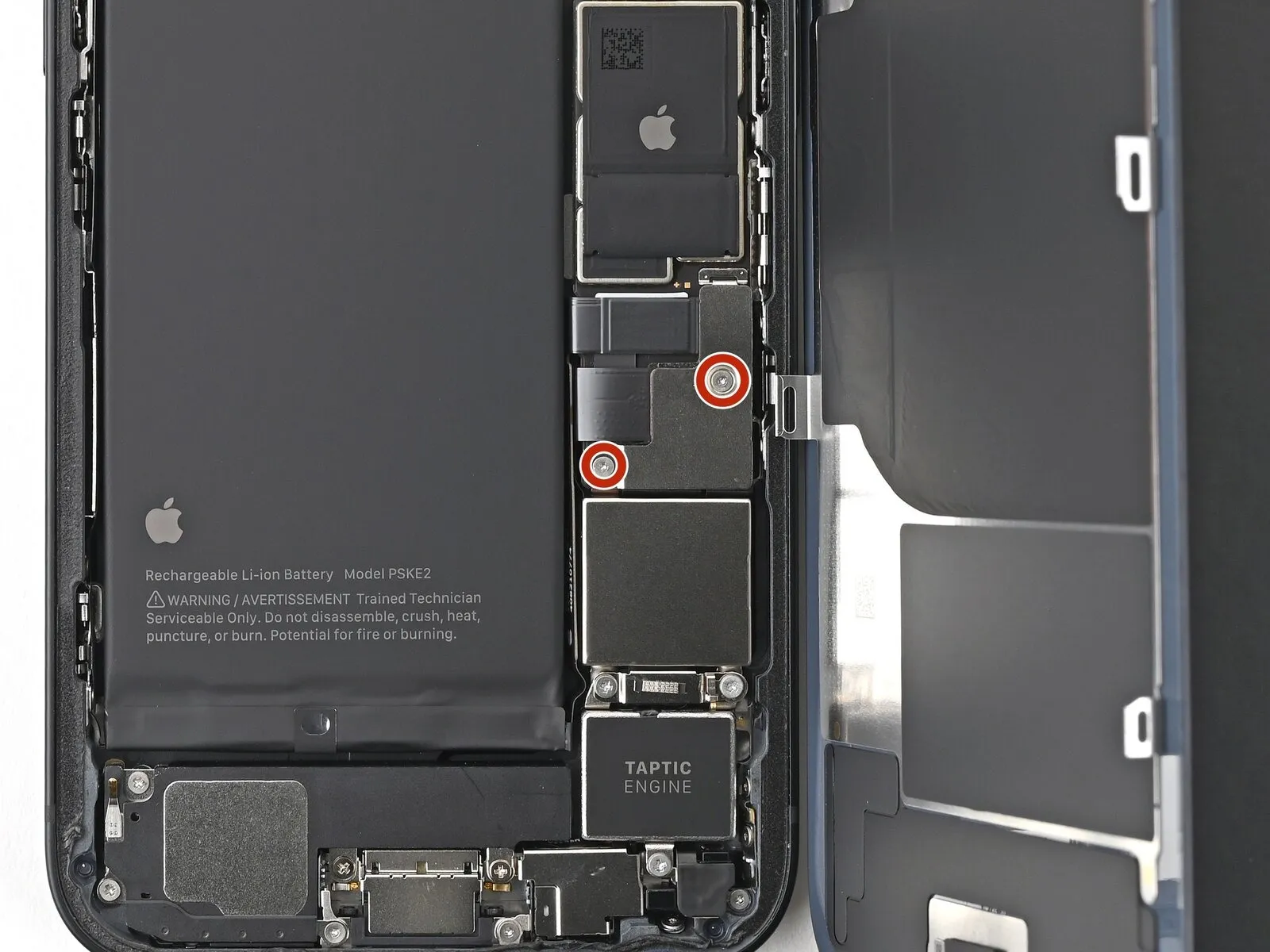
Step 16 | Remove the lower connector cover screws

Step 17 | Remove the battery bracket
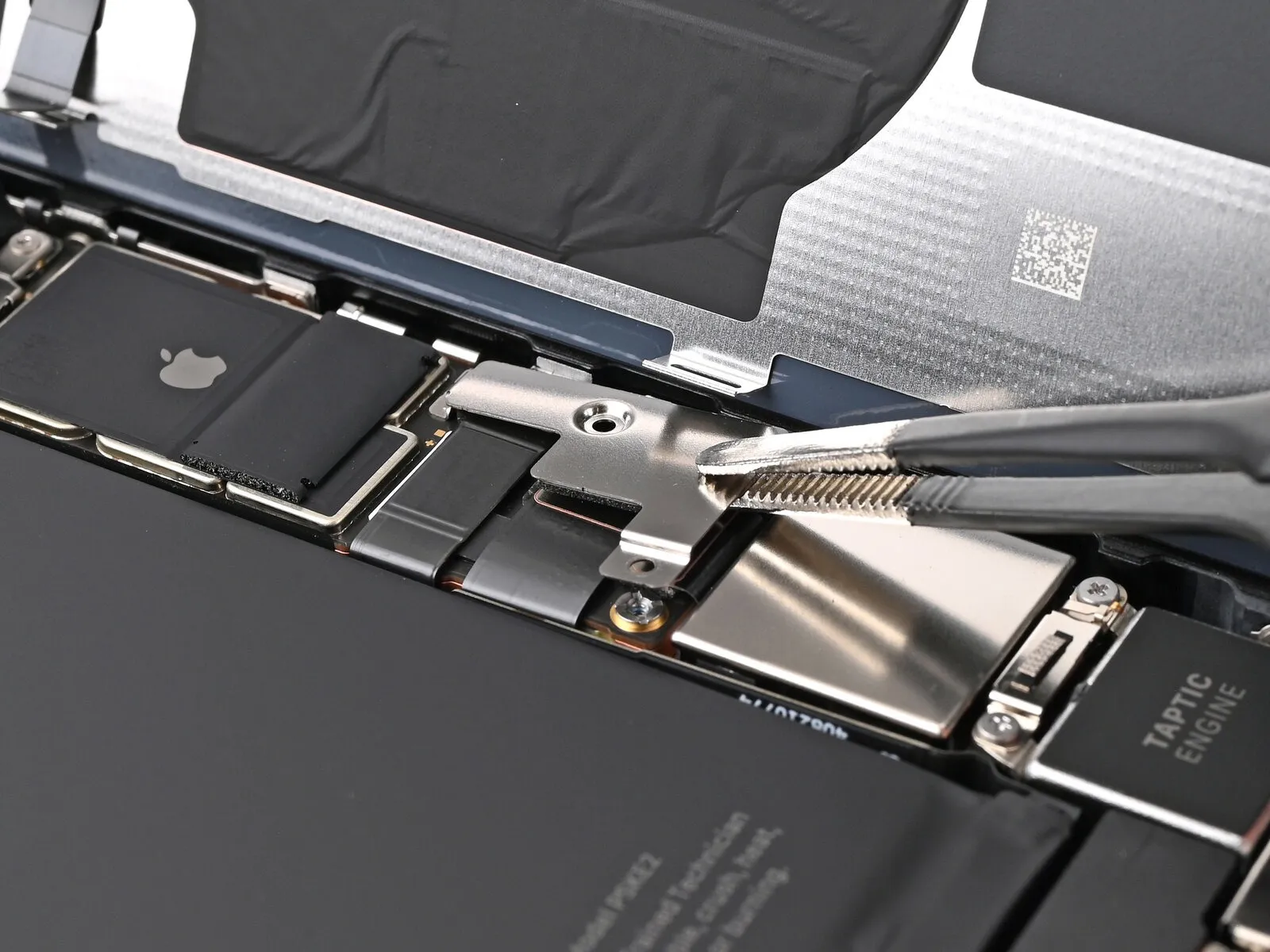


- Employing tweezers or direct finger manipulation, carefully elevate the lower connector cover, then advance it upwards along the device's chassis to disengage it from the securing metal clip.The lower connector cover's release from the metal clip allows for its subsequent removal.To facilitate access to the connectors beneath, the lower connector cover must be detached.
- Ensure the lower connector cover is completely freed from the metal clip before proceeding with its removal.
Step 18 | Disconnect the battery


- Employing the tip of a spudger, carefully lift and detach the battery press connector.
Step 19 | Remove the middle connector cover screw
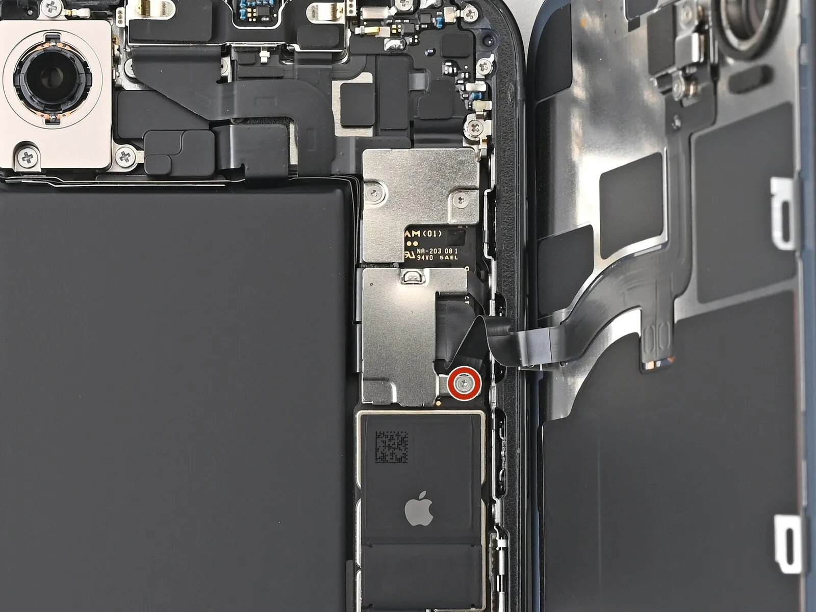

Step 20 | Remove the middle connector cover


- The central connector cover engages with two metallic retaining clips, one positioned at the top and the other at the base.
- Employ the tip of a spudger tool to gently displace the middle connector cover downward, disengaging the clips securing it.
- Alternatively, utilize tweezers or manual dexterity to accomplish the removal.Carefully manipulate the tool or fingers to avoid damage to surrounding components.Successful detachment of the cover is achieved by releasing the clips via controlled pressure.
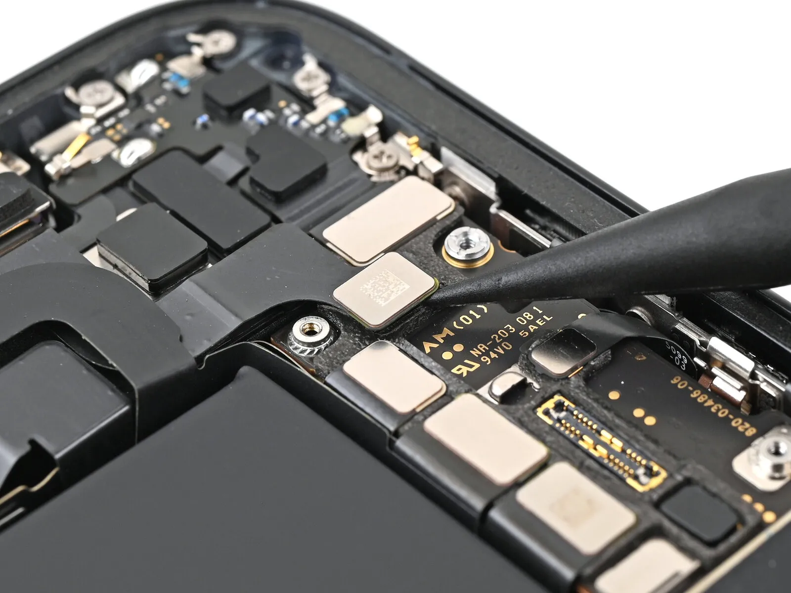
Step 21 | Disconnect the wireless charging coil


- Employing the tip of a spudger tool, gently lift and separate the wireless charging coil press connector to release its connection.
Step 22 | Remove the back glass

- Carefully detach the back glass component from the surrounding frame structure to facilitate its removal.
Step 23 | Remove the top connector cover screws


- Employ a tri-point Y000 screwdriver to detach the two screws that hold the top connector cover in place.
- A single screw, measuring 1.0 millimeters in length, is utilized.A separate screw, with a length of 1.3 millimeters, is also present.
- Ensure the Y000 screwdriver is properly seated on the screw heads to prevent damage.Carefully unscrew and retain both screws for reassembly.
Step 24 | Remove the front camera bracket


- The front camera bracket can be disengaged using either tweezers or direct finger manipulation.
Step 25 | Disconnect the front camera assembly


- Employing a spudger's pointed end facilitates the separation of the two front camera assembly press connectors.
Step 26 | Remove the front camera assembly


- Utilize the pointed end of a spudger to create a separation between the front camera assembly and the device's frame.
- Elevate the front camera assembly by applying gentle leverage with the spudger, continuing until a secure handhold can be established.
- Carefully detach the front camera assembly from the device.
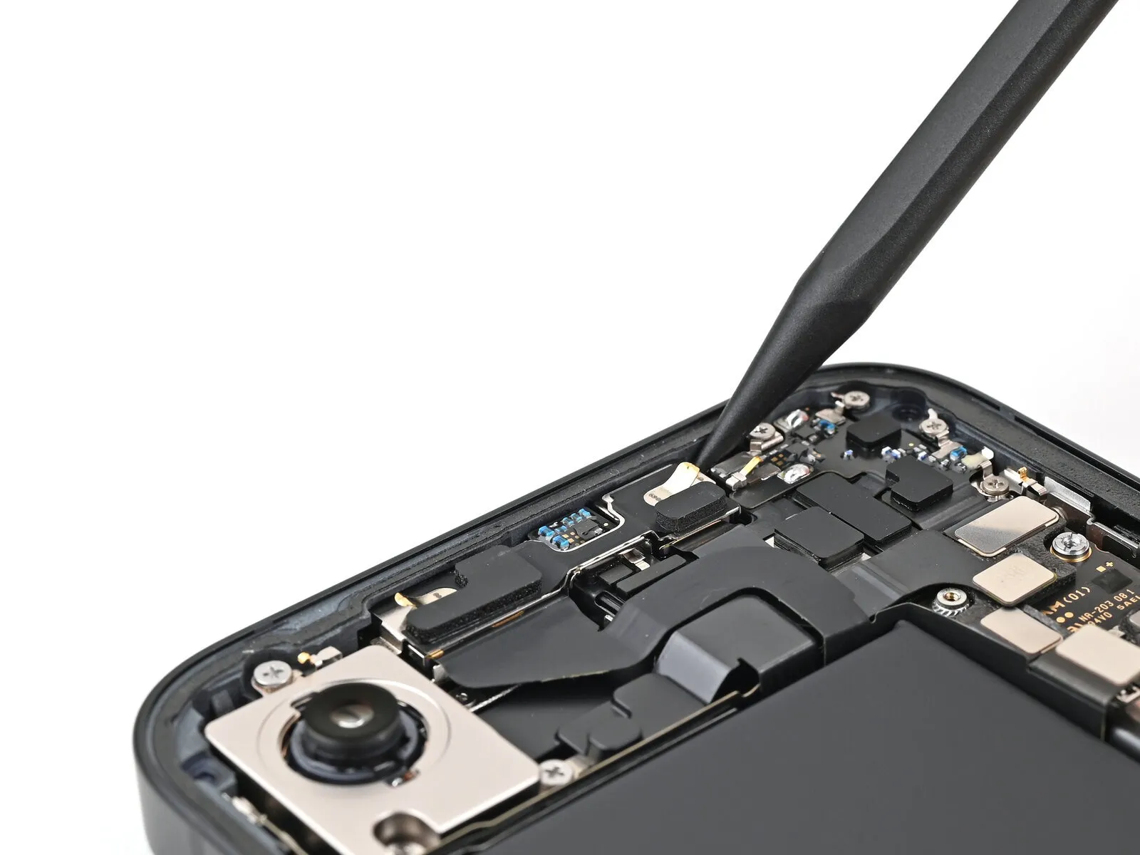
Step 27 | Disconnect the rear camera assembly


- Disconnecting the rear camera assembly press connector requires utilizing a spudger's pointed end to lever it free.
Step 28 | Remove the rear camera assembly screws


- Employ a Phillips screwdriver to detach the three screws that hold the rear camera module in place.
- Two screws, each measuring 2.3 millimeters in length, are present.A single screw, with a length of 2.5 millimeters, is also required.Utilize a standoff screwdriver to disengage the one screw that secures the camera spacer.
- This screw has a length of 2.4 millimeters.The rear camera assembly is fastened by three screws, necessitating a Phillips screwdriver for their removal.For disassembly, the three screws affixing the rear camera assembly must be addressed with a Phillips screwdriver.
- The camera spacer is held in position by a single screw, which demands a standoff screwdriver for removal.A 2.4-millimeter standoff screwdriver is needed to release the screw securing the camera spacer.To release the rear camera assembly, a Phillips screwdriver is essential for extracting the three screws that maintain its position.
Step 29 | Remove the camera spacer


- Employ tweezers or manual dexterity to extract the camera spacer.
Step 30 | Remove the rear camera assembly


- Employing the pointed end of a spudger, gently pry the rear camera assembly free from its housing, allowing for a secure hand grasp once separation begins.
- Complete the removal process by detaching the rear camera assembly from the device.
Step 31 | End of disassembly

Step 32 | Place the rear camera assembly


Step 33


Step 34 | Place the camera spacer


Step 35 | Install the rear camera assembly screws

- A quantity of two screws, each measuring 2.3 millimeters in length, is required.A single screw, with a length of 2.5 millimeters, must also be used.
- A standoff screwdriver is necessary to install the screw that measures 2.4 millimeters in length.The 2.4 mm screw serves to secure the camera spacer.
Step 36 | Connect the rear camera assembly

Step 37 | Place the front camera assembly


- Carefully position the front-facing camera module within its designated space on the device's frame.
- Apply downward pressure to the camera assembly until it rests flush against the frame surface.
Step 38


- To ensure proper connection, guide the connector for the rear camera assembly's cable into its designated receptacle situated near the battery.
Step 39 | Reconnect the front camera assembly


Step 40 | Install the top connector cover bracket


- Secure the upper front cover onto the logic board, ensuring it aligns and engages with the three press-fit connectors.
Step 41 | Install the top connector cover screws

- A single screw, measuring 1.0 millimeters in length, is present.Additionally, a second screw with a length of 1.3 millimeters is also secured.
- Carefully manage these small fasteners to prevent loss or damage.Proper handling of the Y000 screwdriver is essential to avoid stripping the screw heads.
Step 42 | Remove the residual frame adhesive


A spudger can be helpful in consolidating the adhesive for easier gripping.To eliminate any remaining adhesive traces, utilize a coffee filter or a lint-free cloth saturated with isopropyl alcohol possessing a concentration exceeding 90%.High-concentration isopropyl alcohol, greater than 90%, is essential for effective residue removal.
Cleaning with a coffee filter or lint-free cloth ensures a residue-free surface after adhesive removal.
Step 43 | Orient the adhesive


Variations in liner color and pull tab placement are possible depending on the specific adhesive being used.
Employ existing frame characteristics, including the camera aperture and edge indentations, to guide the adhesive's proper alignment within the frame.
Step 44 | Apply the adhesive


Initiate the peeling process of the adhesive's backing liner from its bottom edge using the provided pull tab, but avoid complete removal.
Maintain the blue liner's position away from the work area while carefully positioning the adhesive to match the iPhone's lower boundary.
Ensure proper alignment of the iPhone’s spring contacts with the liner’s corresponding openings by seating the adhesive’s lower edge within the frame’s designated cavity.
Step 45


- Gradually remove the protective backing from the adhesive strip, ensuring firm contact with the iPhone's perimeter during application.
- Proper alignment of the lower edge of the adhesive will result in automatic positioning of the side and top edges; if misalignment occurs, discard the adhesive and repeat the process with a fresh strip.
- Should a replacement adhesive strip be unavailable when misalignment occurs, the iPhone can be reassembled and used temporarily without adhesive; however, be aware that water resistance capabilities will be reduced until a new adhesive strip is installed.
Step 46 | Press the adhesive into place


Step 47


Step 48


Step 49 | Connect the press connectors


Step 50 | Place the middle connector cover


Step 51


- Apply downward pressure to the cover using your finger to secure it against the logic board's surface.
- Simultaneously, move the cover in an upward direction, ensuring that the two metal clips engage properly within their designated recesses on the logic board.
Step 52 | Place the lower connector cover


- Employing tweezers, position the upper edge of the lower connector cover precisely onto its designated location within the logic board.
- Ensure the lower connector cover rests securely upon the press connector.
Step 53 | Install the cover screws


- Employ a specialized tri-point Y000 screwdriver for the installation of the specified screws.The screw's length is precisely 1.0 millimeters.This screw's purpose is to fasten the middle connector cover in place.
- Two additional screws, also requiring a tri-point Y000 screwdriver for installation, are needed.These screws are each 1.3 millimeters in length.The lower connector cover is secured with these longer screws.
Step 54 | Remove the final liners


- Employing tweezers, grasp the protruding tabs located on each of the three 'Blue Liners' to detach them, revealing the underlying adhesive.
- To ensure complete removal of the liner along the right side, it might be necessary to support the rear glass, preventing contact with the adhesive, during the peeling process.
Step 55 | Place the back glass


- Precisely align the new back glass component with the telephone's chassis before proceeding with installation.
Step 56


- Position the rear panel horizontally on the device chassis, applying pressure to secure it with the retaining clips.The back glass should be placed flat against the frame, allowing the integrated fasteners to lock into position.To confirm complete engagement of all retaining clips, apply even pressure across the entire circumference of the rear panel.
- Ensure a firm connection between the back glass and the frame by distributing pressure uniformly around the edges.
Step 57 | Heat the back glass


- Facilitate the adhesive's adherence by warming the back glass's borders with an iOpener, hairdryer, or heat gun, ensuring they reach a warm surface temperature.Apply consistent pressure around the back glass's outer boundary to enhance the adhesive connection.Employ screen vise clamps, if available, to reinforce the newly applied adhesive's bond.
- For securing the back glass without clamps, proceed to the following instructions for alternative methods.
Step 58 | Press the back glass


- Consistent pressure across the iPhone's surface is essential for proper back glass adhesion and frame reinforcement, necessitating consideration of the camera module's protrusion.
- Should the original iPhone packaging be available, utilize the box lid as a stable work platform; otherwise, proceed directly to an alternative procedure.
- Position the iPhone, with the display facing upwards, within the box lid, ensuring the camera bump aligns with the designated indentation.
- Locate an object with a height exceeding the box's sidewalls but approximating the iPhone's width, and position it atop the device, subsequently adding several substantial weights.
- Maintain the applied pressure for a minimum of thirty minutes; reduce this duration proportionally to the weight's mass, with overnight stabilization being the optimal timeframe.
Step 59


- In the absence of the iPhone's original packaging, alternative procedures can be implemented to ensure uniform compression of the rear glass panel.
- Position the iPhone with its display facing downwards upon a cushioned, level surface.
- Adhesive tape should be applied to the rear glass to safeguard its cosmetic appearance.
Step 60


- To create a consistent separation, position a single layer of coins, or alternative items possessing a comparable thickness, directly atop the adhesive tape situated along the perimeter of the rear glass.
- The number of coin layers required may vary; ensure the total thickness of the stack is equivalent to or greater than the height of the camera module’s protrusion, based on the coin thickness.
Step 61

- To apply pressure for bending, place several books or similarly weighty items directly atop your iPhone.
- Because coins can create marks, avoid using precious or irreplaceable materials as the base surface beneath the applied weight.
- Maintain the applied pressure for a minimum of thirty minutes; if the weighting objects are less dense, extend this duration, with an overnight period being the optimal timeframe.
Step 62 | Install the pentalobe screws
- Employ a P2 pentalobe screwdriver for the installation process.The required tool is a P2 pentalobe screwdriver.Two screws, each measuring 7.8 millimeters in length, must be affixed.Secure the 7.8 mm screws to the device's chassis.Position the screws on both lateral aspects of the charging port interface.