iPhone 17 Pro Screen Replacement
This guide details the procedure for substituting a damaged, fractured, or malfunctioning display assembly on an iPhone 17 Pro.
- Ensure the new component is properly installed, adhering to all original specifications and measurements.Ensure the display accurately reproduces color variations by enabling this feature.Automatic screen brightness functionality might not work until you use the Apple Repair Assistant to perform a screen calibration.
- Replacement displays not manufactured by the original equipment manufacturer could fail to achieve proper functionality.Ensure the display accurately reproduces color variations by enabling the True Tone feature.Restore the automatic screen brightness adjustment feature.
A replacement is required.Secure the display panel using adhesive specifically designed for screens, ensuring complete coverage of the bonding area as indicated in the service manual.Ensure all preceding steps have been successfully executed.
Step 1 | Safety precautions


To prevent fire hazards, ensure the iPhone's battery level drops below 25% prior to commencing the repair procedure; a fully charged lithium-ion battery poses a fire risk if compromised.
- Disconnect all wires and cords connected to the device.
- Simultaneously press and maintain the power button along with one of the volume buttons, and then move your finger across the screen to initiate the power-off sequence.
Step 2 | Cracked glass preparation


Because broken glass fragments may hinder the repair process or create a safety hazard, proceed to the next step if your device has a cracked screen.
- Cover the entire fractured surface of the glass with packing tape to secure the fragments and provide a suitable bonding area for the suction cup.
- Apply a non-overlapping strip of tape, sized to accommodate a suction cup, along the entire lower edge.
- Apply the masking tape solely to the glass surface, ensuring no adhesive contacts the frame.
To safeguard your eyes from potential glass fragments that may detach during the repair process, it is advisable to use safety glasses.
Step 3 | Remove the pentalobe screws


Employ a 3/8-inch socket wrench to tighten the fastener to a torque of 15 Nm, ensuring caution is exercised to prevent damage to the retaining clip.Use a P2 screwdriver with a pentalobe tip.Detach the pair of fasteners.Screws measuring 7.5 millimeters in length.Flanking the charging port are components on both the left and right sides.
Step 4 | Mark your opening picks


To avoid potential damage to your device, ensure the opening pick does not extend beyond a safe depth; therefore, carefully mark the pick's insertion point to prevent over-insertion.
- Determine the dimension using a measuring tool.Three millimeters.Using a permanent marker, indicate the opening point on the pick.
- To secure the component, adhesive tape can be used, with a coin serving as a temporary spacer.Three millimeters.Using the pointed end of the pick, proceed.
Step 5 | Heat the bottom edge

Employ a 3/8-inch socket wrench to loosen the fastener, ensuring you apply consistent pressure to avoid stripping the threads, and subsequently remove the retaining clip.Utilize a device designed to emit warm, directed airflow, ensuring the unit's wattage is no greater than 1500W and its cord is undamaged, to gently warm the component.orApply heat using a tool designed to generate warm air, ensuring the temperature remains consistent.Apply heat to the screen's lower edge, ensuring the temperature reaches a point just beyond comfortable touch, but be cautious to avoid exceeding safe operating limits.Apply warmth with a device capable of generating controlled heat.Improper execution may result in damage to the screen or battery; adhere strictly to the detailed procedures provided in the accompanying documentation.
Step 6 | Apply a suction handle


Using a suction tool, carefully secure the lower screen edge, positioning it as near as possible to the perimeter.
Step 7 | Screen bezel information


Carefully position your pick at the designated spot for the subsequent procedure.
- A molded plastic component is present.Secure the 40mm diameter trim piece around the display screen, ensuring proper alignment with the existing markings and using the provided specialized tool to avoid scratching the surface.Position your pick beneath the screen's lower edge, ensuring full separation from the frame.Secure the 42mm diameter ring around the watch case, ensuring proper alignment with the crystal..
- A molded joint exists where two plastic components meet.Secure the 42mm diameter ring around the watch case, ensuring proper alignment with the crystal and using the specialized tool to tighten it evenly.Avoid inserting the pick into this area, as doing so will detach the display panel, making the repair process more difficult.
Step 8 | Insert an opening pick


Apply firm, consistent upward pressure to the suction handle to create separation between the display screen and its surrounding frame.
Applying considerable pressure might be necessary; if detachment proves difficult, reapply heat to the display and attempt separation once more.
Carefully guide the pointed end of aUse a specialized tool designed for prying, often referred to as a pick.Position the component within the newly formed space.
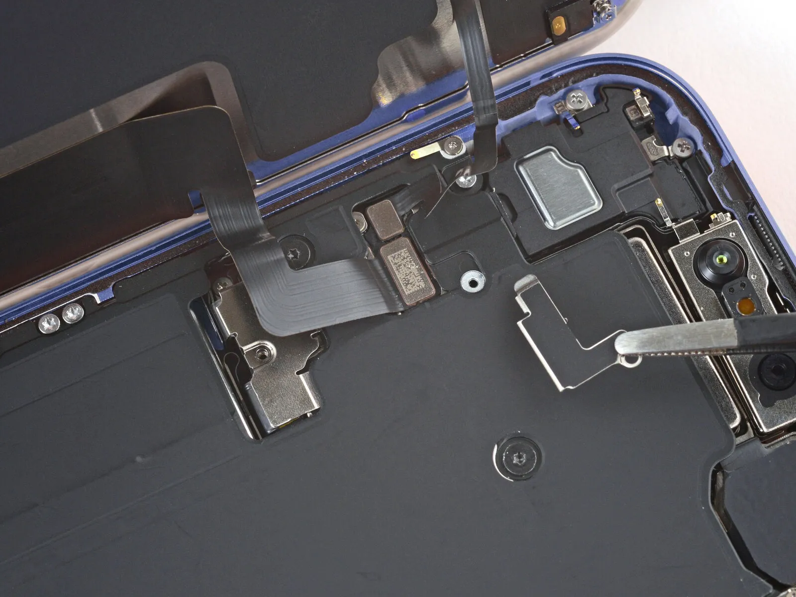
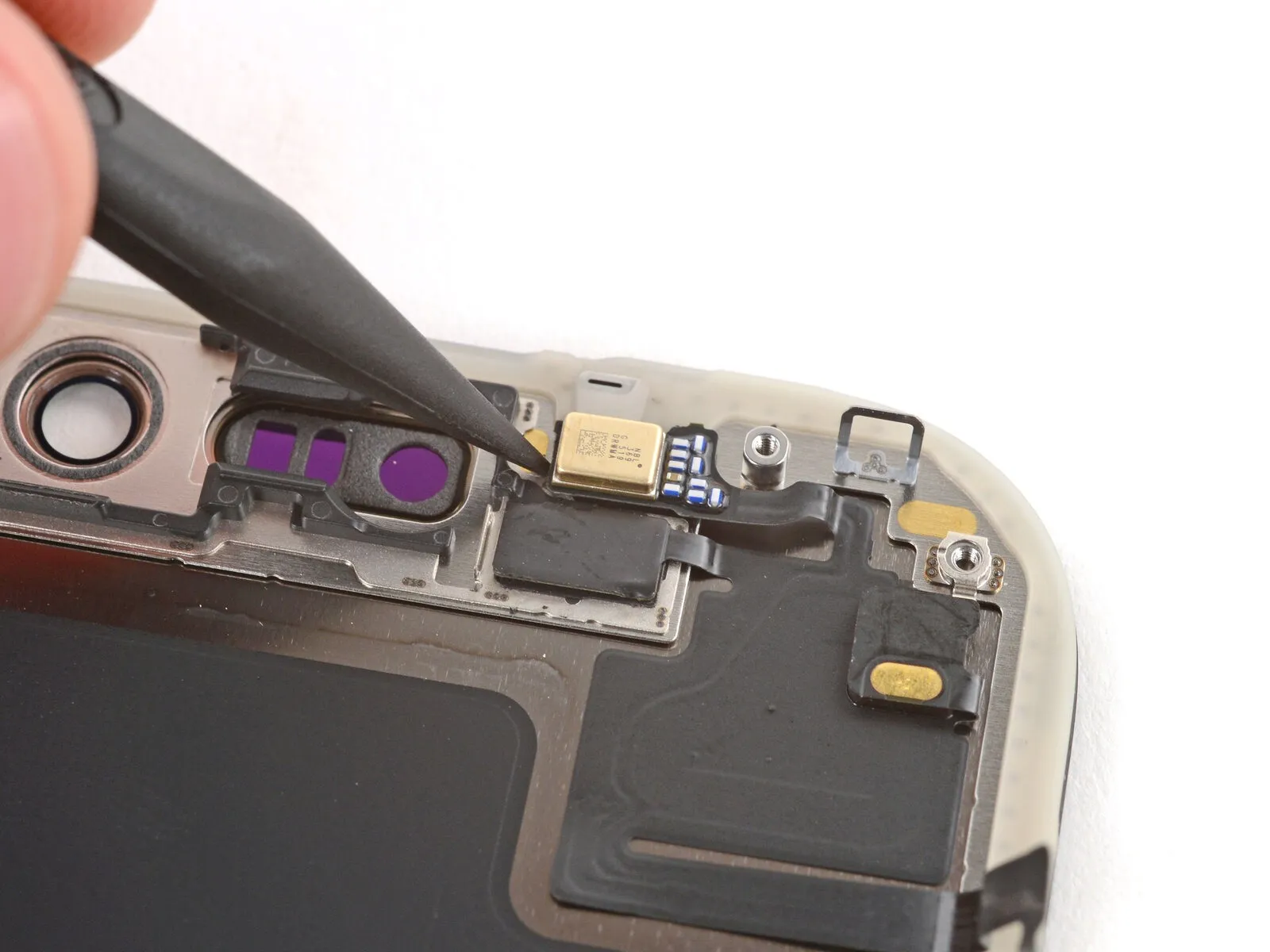
Step 9 | Screen information

Avoid inserting the tool beyond the specified depth.Three millimeters.To prevent harm to the subsequent components, ensure work is performed beneath the display surface.
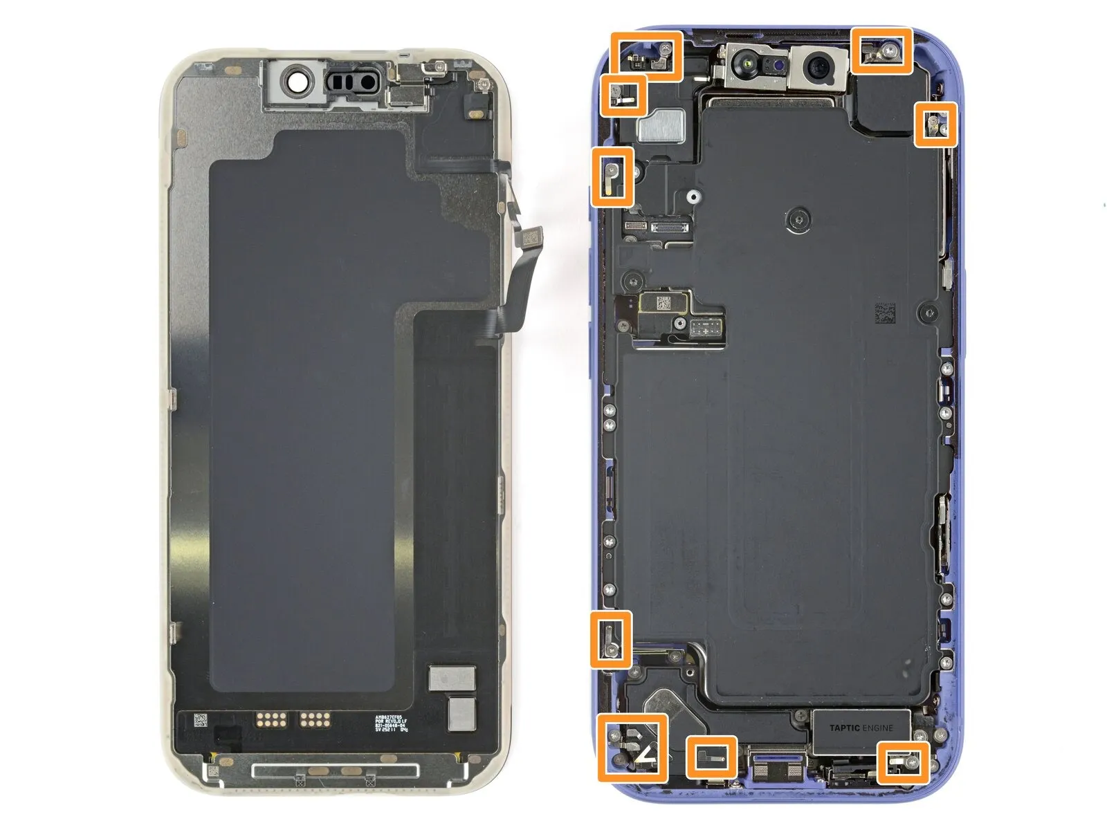
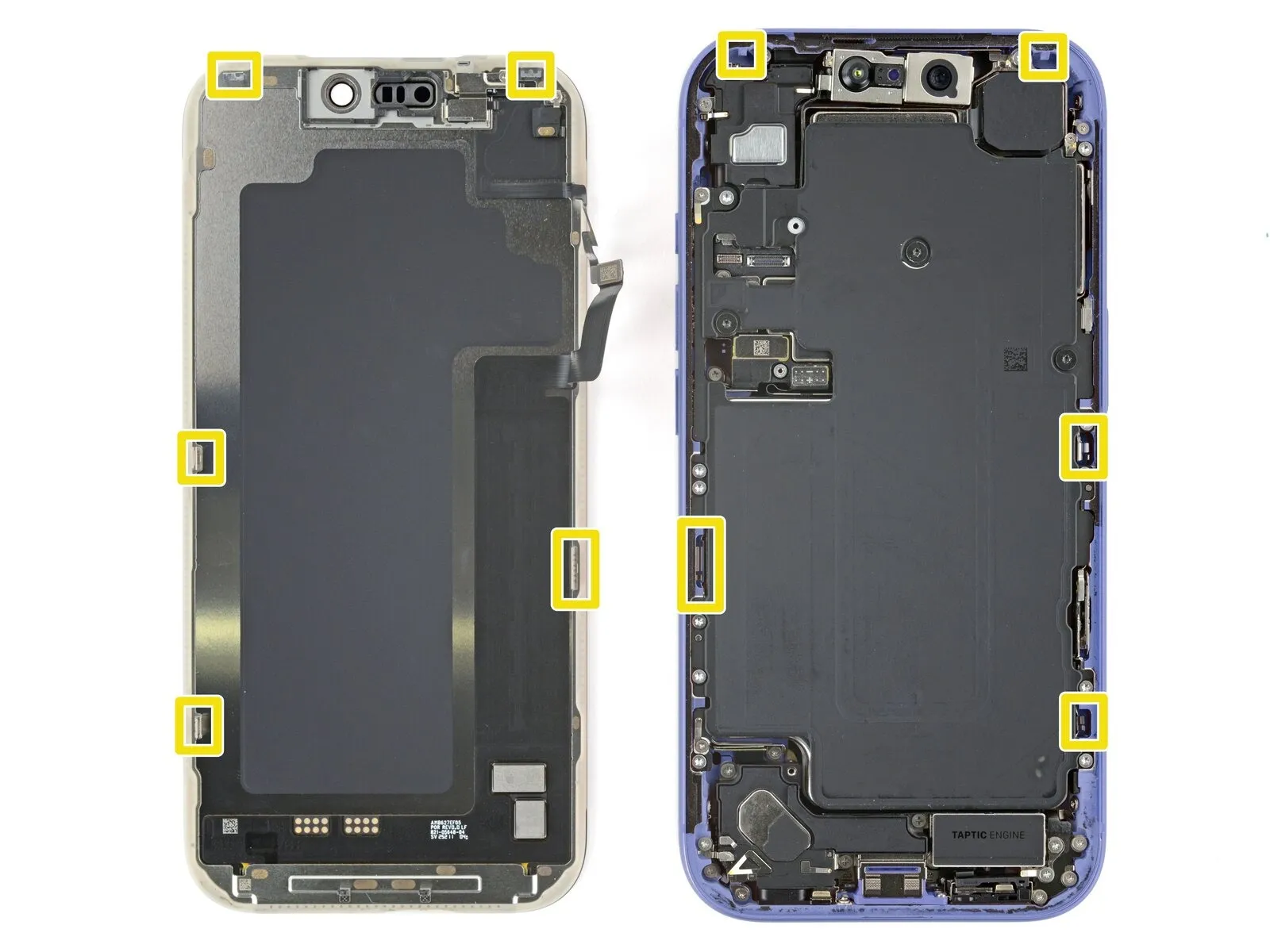
- Close to the volume and Action buttons, you’ll find the cables connecting the screen and ambient light sensor.
- Carefully inspect the phone's edge for small, sensitive spring-loaded connectors.
- Metal clips, located on the screen's lower surface, secure it to the frame via matching slots.
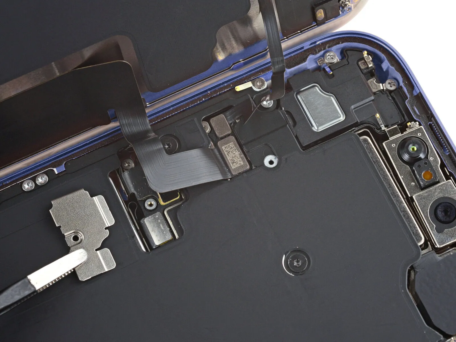
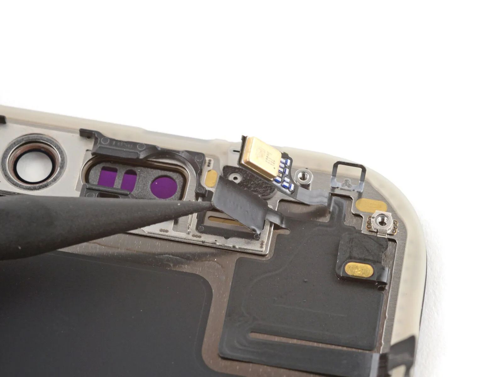
Step 10 | Separate the bottom edge adhesive


Using the opening pick, carefully work along the lower border to release the adhesive bond.
To stop the adhesive from bonding again, maintain a small gap by keeping the pick positioned beneath the lower right corner.
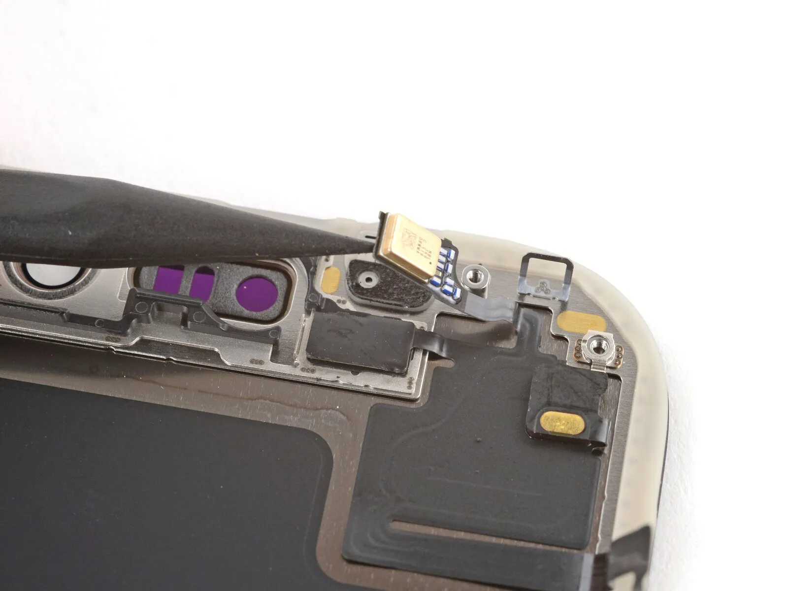
Step 11 | Remove the suction handle

Step 12 | Heat the right edge


Apply warmth to the right side of the component using a heat gun or hair dryer.Carefully detach the display panel, noting that it is secured with adhesive and requires gentle prying using a plastic opening tool to avoid scratching the surface or damaging the surrounding components; the screen measures 6.5 inches diagonally and incorporates a flexible display cable that must be handled with care to prevent breakage.The component should reach a temperature just beyond comfortable touch.
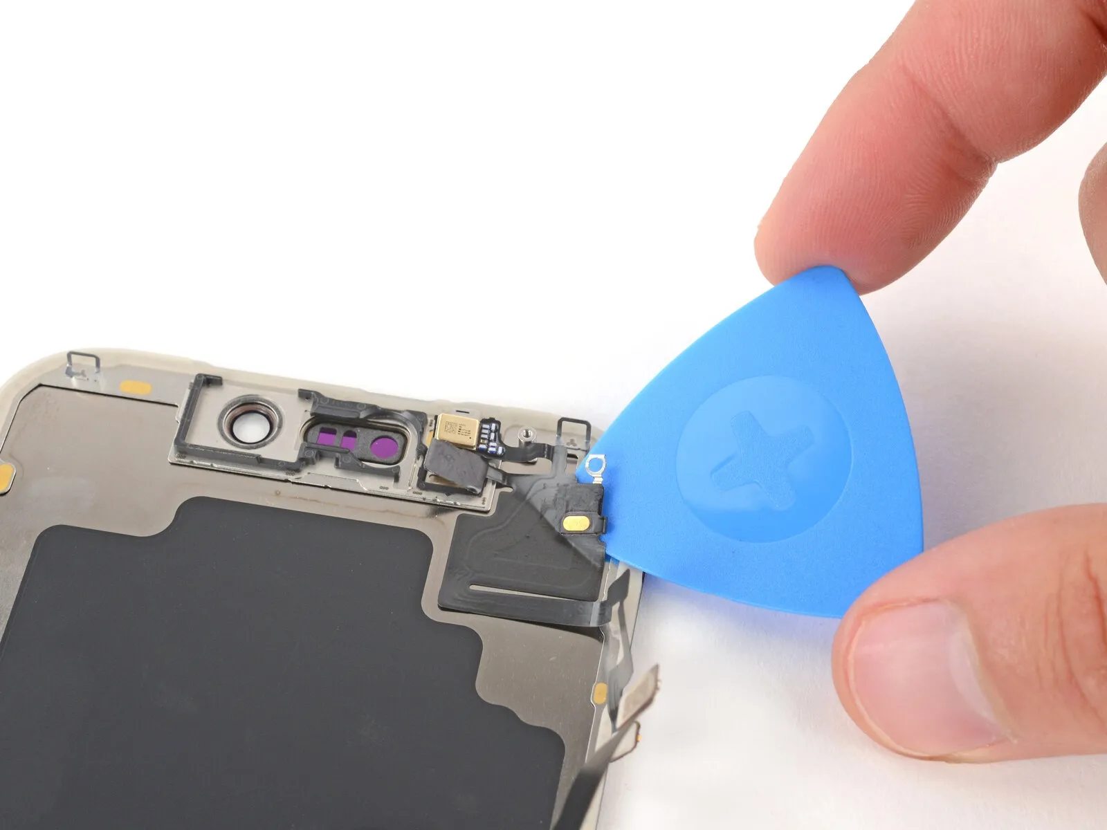
Step 13 | Separate the right edge adhesive


- Using a specialized opening pick, carefully slide it beneath the screen's lower-right corner.
- Using a pick, carefully lift the right edge to break the adhesive bond and disengage the two clips.
- Gently lift the screen a small amount to disengage the retaining clips.
- To stop the adhesive from bonding again, maintain a small tool in the upper right corner.
Step 14 | Heat the top edge


Apply warmth to the screen's upper border with a hair dryer or heat gun, ensuring the surface reaches a temperature just beyond comfortable touch.
Step 15 | Separate the top edge adhesive


- Using a third opening pick, carefully slide it between the screen and the device's frame, positioning it directly beneath the upper right corner.
- Using a pick, gently work it along the upper edge, extending just past the upper left corner, to loosen the adhesive and disengage the two clips.
- To prevent damage to the ambient light sensor cable, ensure the pick remains at its current position and does not advance further.
- To stop the adhesive from bonding again, maintain a small tool in the upper left corner.
Step 16 | Heat the left edge


Apply warmth to the left screen perimeter with a hair dryer or heat gun, ensuring the surface reaches a temperature just beyond comfortable touch.
Step 17 | Separate the left edge adhesive


- Using a specialized opening pick, carefully slide it beneath the screen's lower-left corner.
- Carefully insert a pick along the right side to break the adhesive bond, disengaging the clip while pausing your movement immediately prior to the volume up button's location.
- Carefully lift the screen a small amount to free the retaining clip, ensuring the repair tool remains shallow to prevent screen cable damage.
Step 18 | Prop up the screen
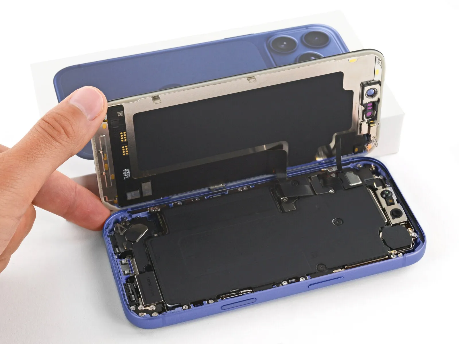
Ensure the display panel is fully released from its mounting; if resistance is encountered, re-examine the edges to disengage any lingering adhesive or securing clips.
Carefully raise the display vertically, pivoting it to the left side, then secure it with a stable support like a box or books to prevent cable stress.
Position the display panel horizontally, ensuring it rests evenly against the left-hand surface.
Step 19 | Remove the cover screws

Carefully organize all screws during disassembly, noting their original locations to ensure correct reassembly.
Employ a Japan Industrial Standard screwdriver.00Use a screwdriver to detach the two screws that hold the cable covers in place.
- Begin the process by executing step one.One point four millimeters.Use a long screw to secure the screen and front sensor cable cover.
- Begin the process by executing step one.One point three millimeters.A screw, specifically long in length, is required for securing the battery cover.
Step 20 | Remove the covers

Detach the two protective housings.
Step 21 | Disconnect the battery
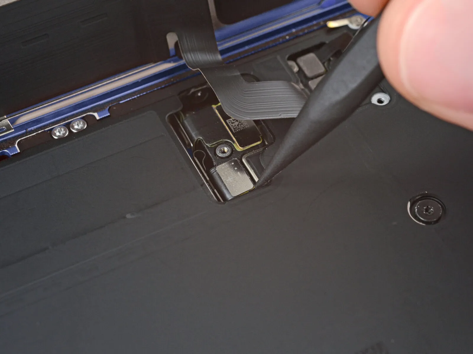
- Carefully insert the tip of a spudger.Use a prying tool to release and separate the battery press connector.
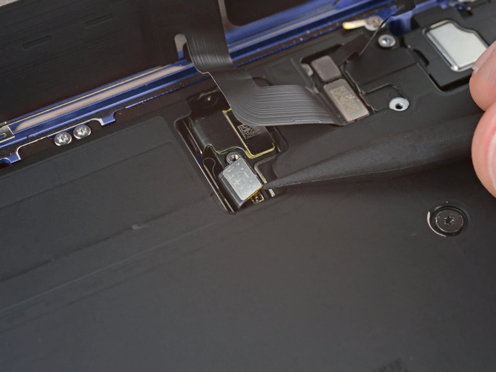
Step 22 | Disconnect the screen


- Employ either the pointed end of a prying tool or a spudger to access tight spaces.Release the retaining clips on the connectors to separate the screen and ambient light sensor assembly.
Step 23 | Remove the screen
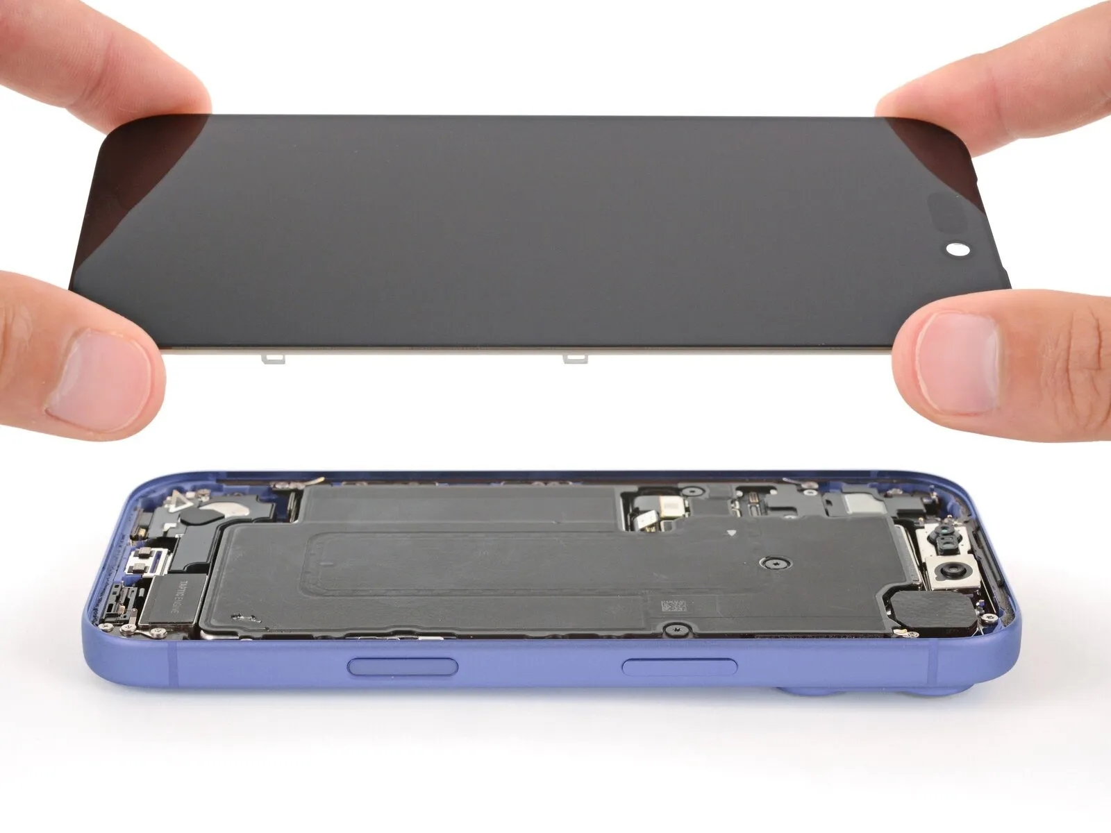
- Carefully detach the display panel, ensuring all retaining screws are removed and any connecting cables are disconnected..
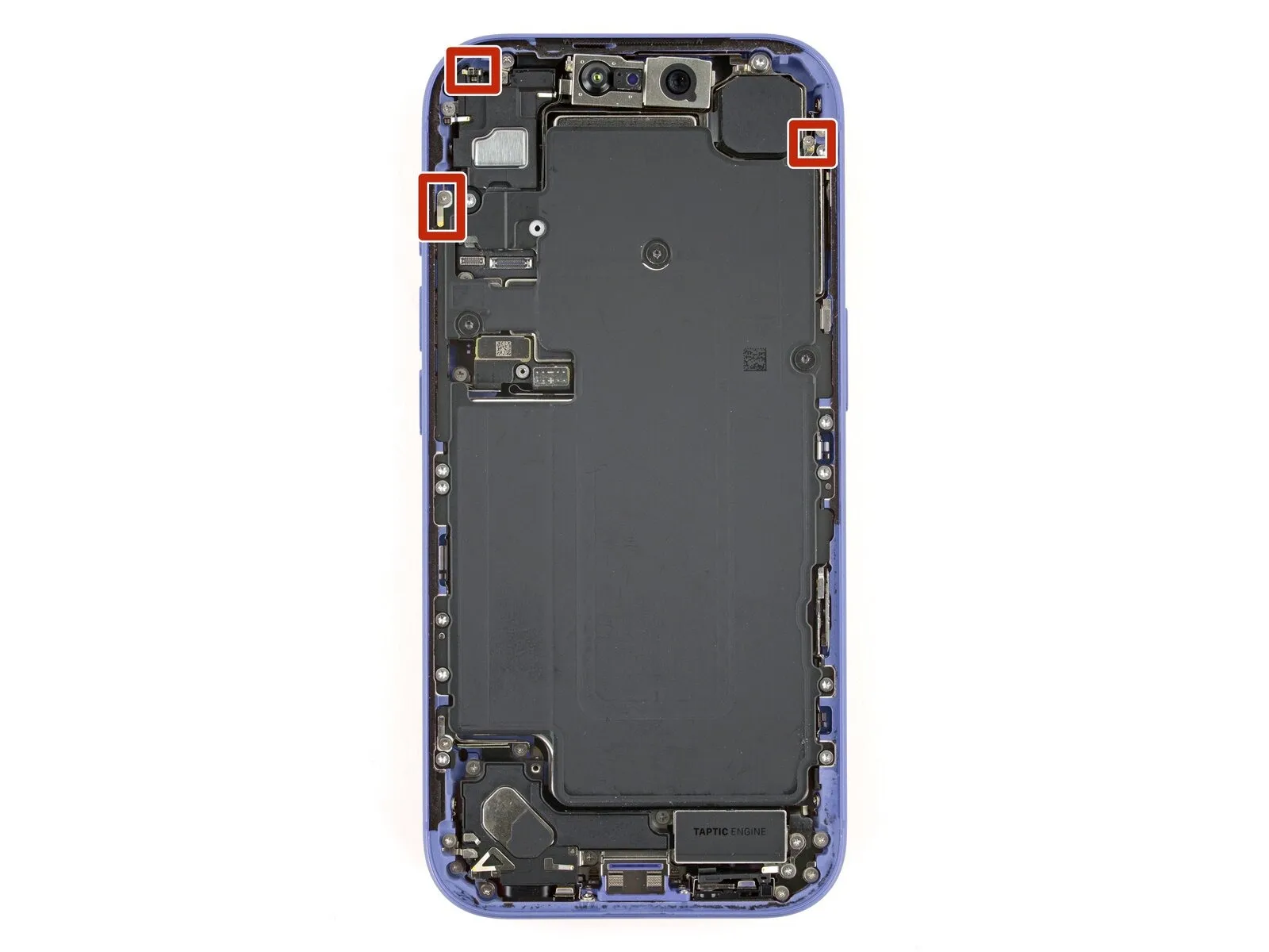
Step 24 | Remove the front sensors screws
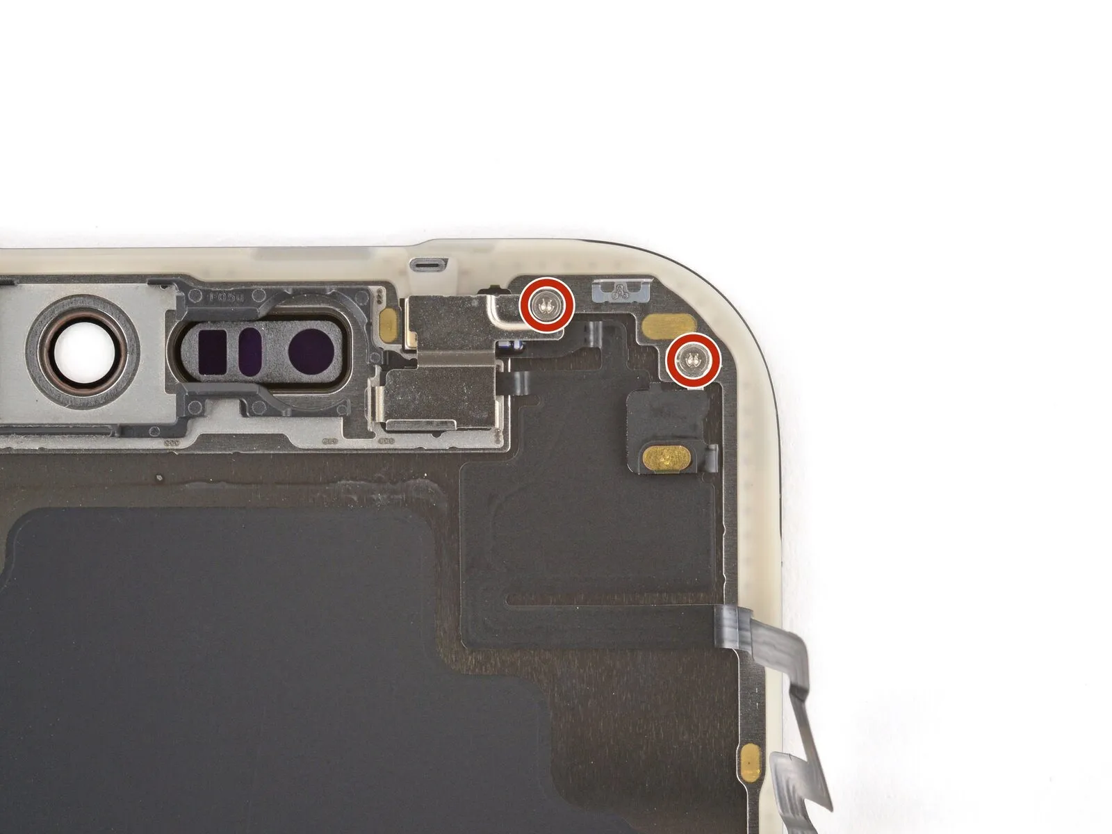
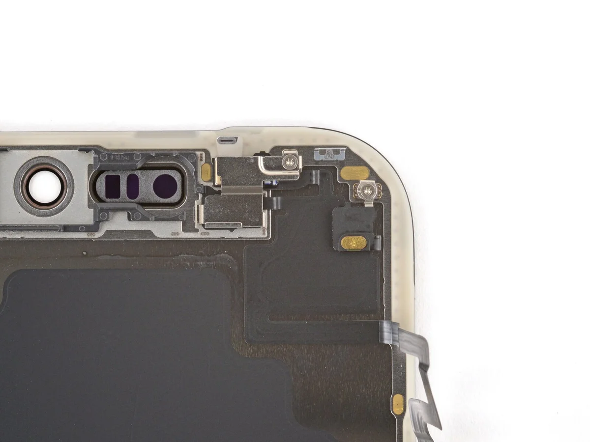
- Ensure the newly installed display lacks pre-attached front sensors.Carefully proceed with the subsequent five steps to detach these components, ensuring they are preserved for relocation to the new display panel.
- Employ a Y000 tri-point screwdriver for this step.Use a screwdriver to detach the two screws securing the front sensors; each screw measures 1.0 mm in length.
Step 25 | Remove the bracket

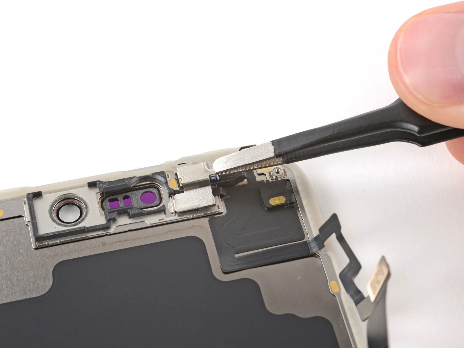
Step 26 | Heat the front sensors

Step 27 | Pry up the sensors
- Please provide the original text you want me to rewrite. I need the sentence or instruction to work with.Locate the forward-facing proximity sensors.Handle these components with extreme care as they are prone to tearing; use a delicate touch during removal. Should you encounter resistance, increase the heat application and attempt the process again.
- Carefully lift both front sensors using a spudger tip.
- To prevent sensor damage, carefully lever upwards on the designated tab located beneath the sensors.
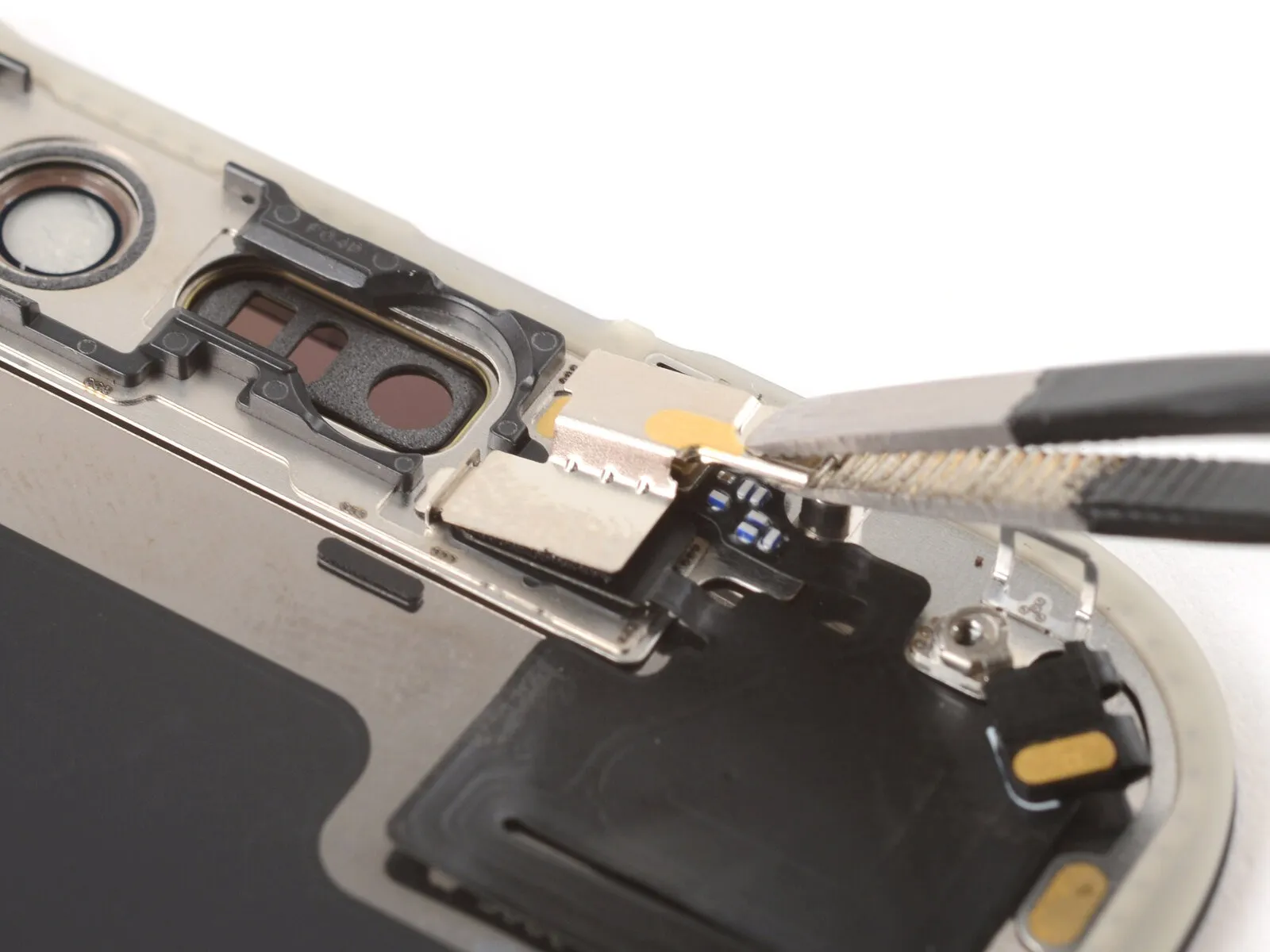
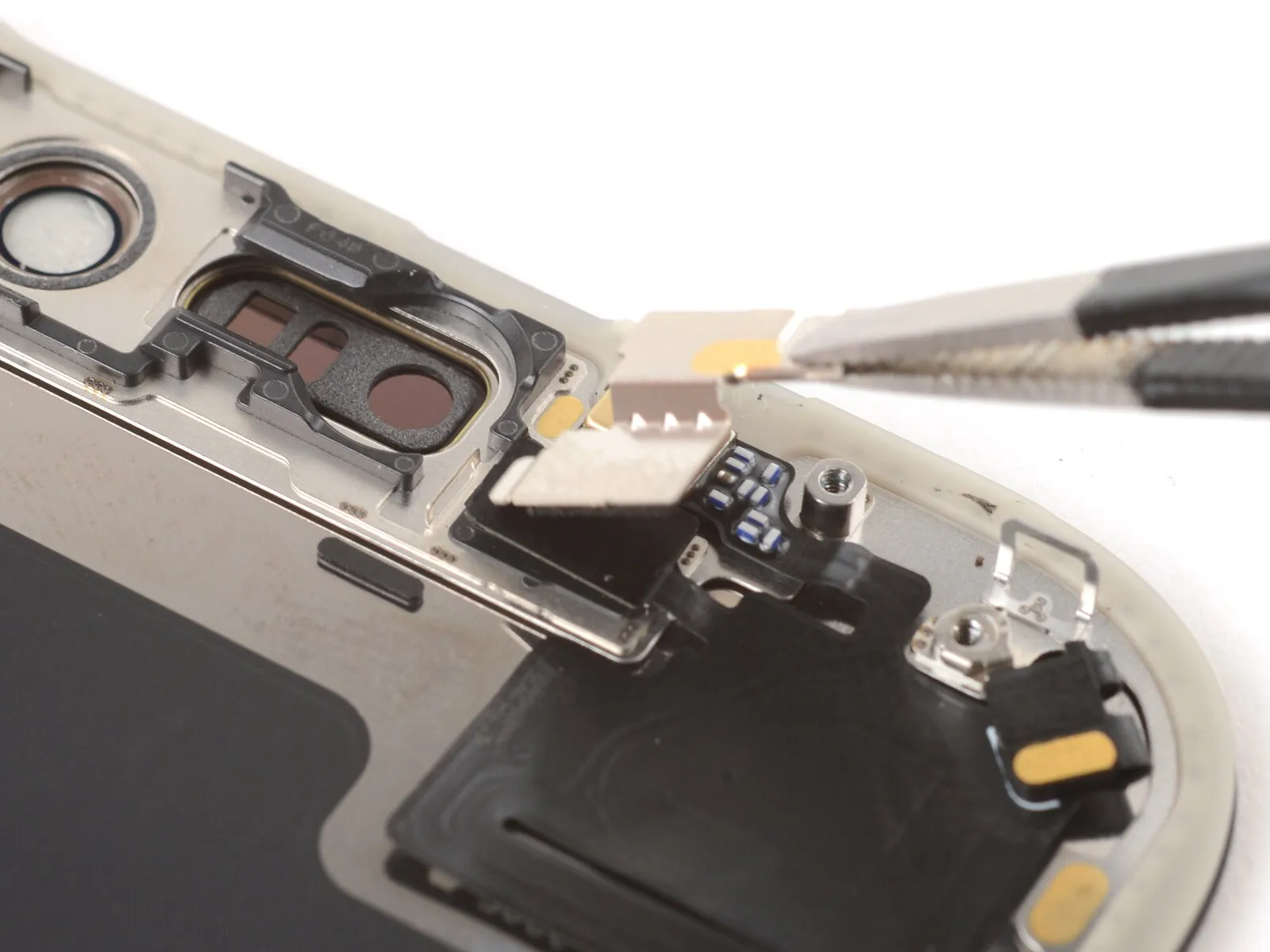
Step 28 | Remove the sensors

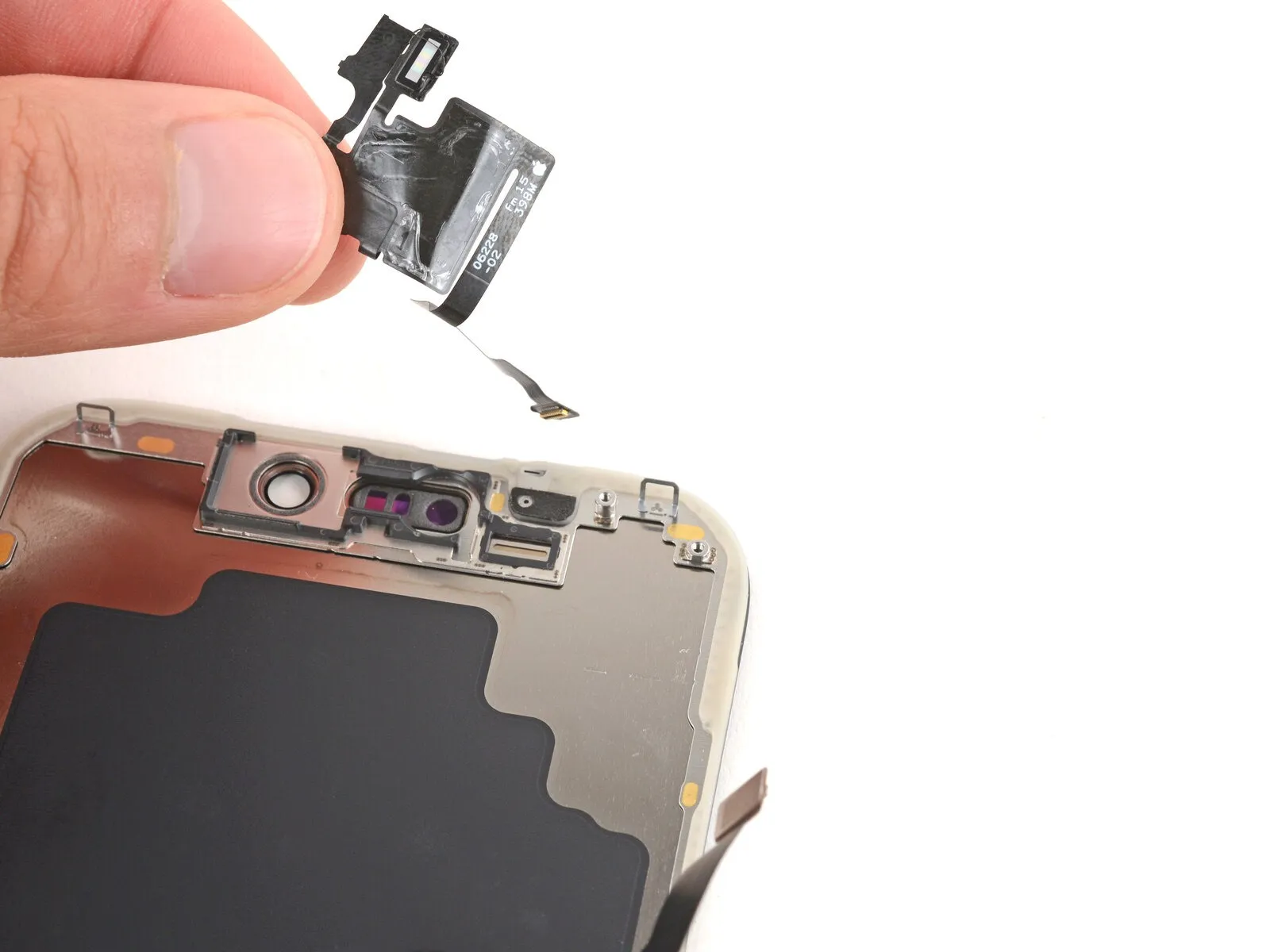
- Using a pick, carefully slide the tip beneath the adhesive securing the large cable connected to the front sensors, focusing on the upper right corner.
- Using a pick, gently work it beneath the cable, raising it until you can grasp it with your hand.
- Carefully lift the cable using your fingertips, then detach the sensors.
- Carefully move the sensors to the new display panel, ensuring their precise placement.
Step 29 | Disassembly complete
With the device now disassembled, proceed to the following instructions to reassemble your iPhone.
Visual differences in the assembly illustrations might occur based on your iPhone's specific design, but the steps remain accurate for all models.
Step 30 | Attach the front sensors

To connect the front sensors, proceed with the following four actions; however, if the replacement screen already has these sensors mounted, advance four steps further.
Apply finger pressure to secure the front sensors cable's rectangular portion against the display.
Apply gentle heat with a hair dryer or iOpener to the adhesive securing the cable, ensuring the temperature remains mild to prevent damage.
To secure a cable that isn't adhering, affix a small portion of double-sided adhesive tape to its rear surface.
Step 31

- Gently depress the component with either a fingertip or a spudger.The surrounding illumination level is detected by this component.Employ a wrench to tighten the fastener to a torque of 15 Nm, ensuring the use of appropriate safety glasses and gloves while handling the component.Use a microphone.Ensure they are fully seated within their designated cavities.
Step 32
- Secure the front sensors bracket by engaging its left tab with the screen, ensuring proper alignment.
Step 33
- Employ a 3/8-inch socket wrench to tighten the fastener to a torque of 15 Nm, ensuring you observe all safety precautions and handle the component with care.Use a Y000-sized screwdriver with a three-pronged tip.Secure the pair using the provided fasteners.Front sensors are secured with screws, each measuring 1.0 mm in length..
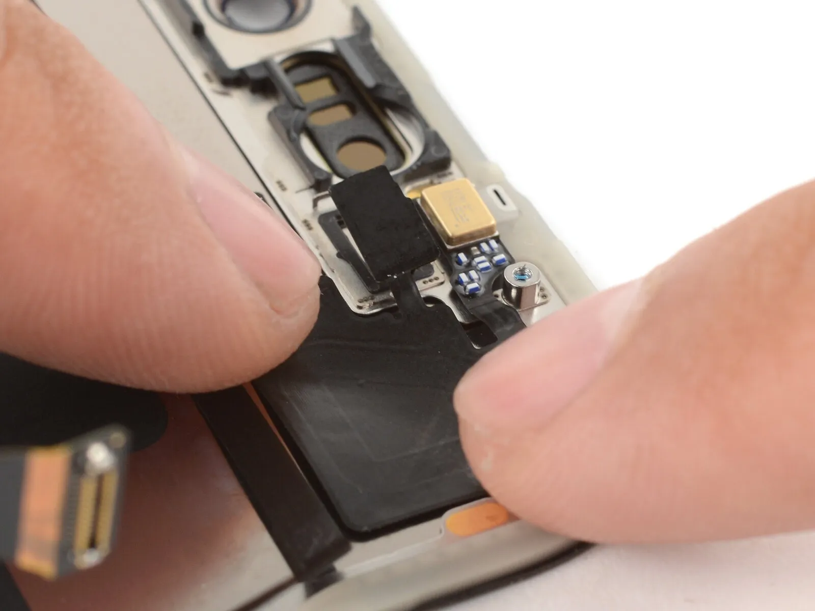
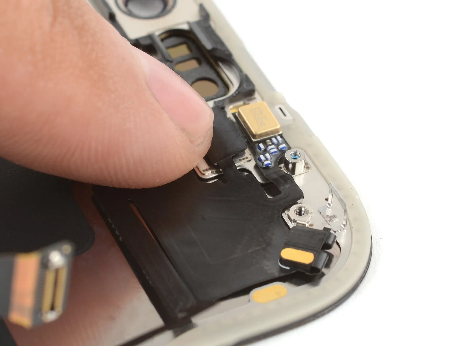
Step 34 | Clean the frame


- Carefully maneuver around the delicate grounding clips during frame cleaning; should any become displaced, restore them to their original position using your fingers or tweezers, applying gentle pressure.
- Employ the specified tool to perform the action.Employ fine-tipped pliers or similar precision instruments.Use your fingers to detach sizable adhesive remnants from the frame's edges.
- Employ a 3/8-inch socket wrench to loosen the retaining bolt, ensuring you apply consistent pressure to prevent damage to the threaded shaft and observe the torque specification of 12 Nm as indicated in the service manual.Use a plastic pry tool, often referred to as a spudger, to avoid scratching surfaces.Carefully remove any remaining adhesive from the frame's surface using a scraper.
- To loosen a firmly bonded adhesive, use heat.Utilize a hair dryer to apply heat, ensuring the device is rated for voltages up to 120V and draws no more than 15 amps, maintaining a distance of at least 6 inches from the component being treated to prevent damage.orApply warmth with a device capable of generating controlled heat.Repeat the process to confirm the desired outcome.
Step 35

- To remove adhesive residue from the frame's edge, gently wipe it clean using a lint-free cloth or a coffee filter, applying even pressure in a single direction.
- To address a tacky or adhesive feel, dispense a small quantity of drops.Use rubbing alcohol, which is isopropyl alcohol.Using a clean cloth, repeat the wiping process.
- Careful execution is essential; a thoroughly cleaned frame surface promotes uniform adhesive distribution, which is critical for optimal bonding.
Step 36 | Clean the screen

Carefully dispense a small quantity of adhesive onto the replacement display panel before installation.Use only isopropyl alcohol with a high concentration.Using a microfiber or lint-free cloth, thoroughly clean the area's edges to ensure a clean surface ready for the new adhesive.
Step 37 | Orient the replacement adhesive


Carefully position the component, ensuring all protective layers remain intact.A self-stick backing facilitates attachment.Position the component atop the frame, ensuring alignment according to its design.
- Carefully observe the frame's top and bottom edges, noting the camera opening and any notches, to help guide the adhesive placement.
Step 38 | Apply the replacement adhesive

Carefully lift the corner edge using the provided tab.A self-stick backing facilitates attachment.Carefully remove the protective backing to reveal approximately one-third of the adhesive surface.Apply a bonding agent..
Carefully access the component by removing any coverings to reveal it.Use a bonding agent.The adhesive is highly viscous; avoid contact with surfaces until you intend to bond it to the frame.
Remove the protective backing layer from the adhesive until the surface designed to bond with the frame is revealed.
Step 39


After the component is secured, proceed with tightening the M4 screws to a torque of 4.0 Nm using a torque wrench.Use a bonding agent.Because it adheres immediately, any misplacement requires complete removal and replacement with fresh adhesive.
Ensure the visible perimeter is precisely positioned.Double-sided tapeAlign the component's border with the iPhone's frame edge.
Ensure proper positioning, then apply light pressure to the visibleEmploy a strip of adhesive material.Securely position the component against the frame.
Step 40


Carefully remove the protective backing layer.Employ a bonding agent.Apply slight pressure to theEmploy a bonding agent.Ensure proper alignment and secure the component.
Ensure proper positioning by verifying that theEmploy a bonding agent.Careful alignment ensures the sides fit precisely.
To ensure proper function, carefully inspect the component, noting any deviations from the specified 1.5mm tolerance, and utilize the calibrated torque wrench to secure it with 8 Newton-meters, observing the safety precautions outlined in section 3.2 regarding potential pinch points.Use a bonding agent.Carefully draw the extended sides toward the frame to correct the minor displacement.
Carefully detach the component, ensuring the 3.5mm connector remains undamaged, and then reattach it, aligning the pins precisely to avoid any misalignment exceeding 0.1mm, using a Phillips #2 screwdriver as needed, while observing the safety warning regarding potential electrical shock.Use a bonding agent.If the material exhibits folding or distortion, discard it and reapply adhesive to a new section.
In the absence of a spare set, proceed with caution.Double-sided adhesive tapeFor convenience, you can briefly reassemble and use your iPhone as usual, even with a temporary fix.Employ a bonding agent.After this step, understand that the iPhone's ability to repel water will be reduced and won't return to its original level unless a replacement seal is installed.Apply a bonding agent..
Step 41

- Employ a spudger for the task.Ensure the adhesive strip is firmly applied by applying even pressure across its full circumference.
Handle the delicate grounding clips with caution; if displacement occurs, restore them to their original position using your fingers or tweezers.
Apply gentle pressure to prevent distortion or extension of the adhesive material.
Step 42


- Grasp the protruding tab to release.Carefully remove the sizable front adhesive liner, locating and utilizing the pull tab, typically situated at a corner, to facilitate separation.
The protective liners remain in place around the edges; leave them undisturbed to avoid unintended adhesive bonding during reassembly of the iPhone.
Step 43 | Connect the screen

Carefully position the replacement display assembly onto the iPhone's frame, ensuring proper alignment before securing it.Position the display panel adjacent to the device's frame, ensuring sufficient cable slack for connection to the logic board.
Step 44


- Apply pressure with a fingertip or the broad, flat surface of a spudger.Carefully align and secure both screen connectors to the logic board, ensuring a firm connection.
Ensure the connector is not inserted with excessive force; if resistance is encountered, adjust its alignment and retry the connection.
Step 45 | Connect the battery


Employ either a fingertip or the broad, planar edge of a spudger tool.Align the battery connector and firmly seat it onto the logic board.
Step 46 | Test your repair

- Before reassembling the iPhone, verify the functionality of your repair by powering on the device and confirming it operates correctly.
- Following power-down, proceed with the remaining assembly steps.
- Attempt to power on the iPhone; if unsuccessful, establish a connection to a power source and repeat the power-on procedure.
Step 47 | Install the battery connector cover


Ensure the battery connector cover's upper edge is fully seated within the designated recess by verifying that both tabs are positioned beneath the lip.
Position the cover so the screw holes match, then set it down.
Step 48

Employ a JIS 00 screwdriver for this task.Secure the component using the specified fasteners, ensuring proper alignment with the designated mounting points as indicated in the parts list and adhering to the torque specifications of 3.2 Nm.A screw measuring 1.2 millimeters in length.Fasten the battery connector cover using the provided screw, ensuring it is tightened to a torque of 5.0 Nm with a 4mm hex key, and observe the warning against over-tightening.
Step 49 | Install the screen connector cover


- Carefully slide the left side of the screen connector cover beneath the designated notch.
- Position the cover so the screw holes match, then set it down.
Step 50

Employ a 3/8-inch socket wrench to loosen the retaining nut, ensuring you apply a steady force to prevent damage to the threaded shaft and observe the torque specification of 15-20 ft-lbs; be cautious of potential spring tension during removal.Use a JIS 00 screwdriver.Utilize a screwdriver for installation.Measure 1.2 millimeters in length.Using the Phillips head screwdriver, fasten the screen connector cover with the screw.
Step 51 | Remove the final adhesive liners


- Secure the display panel with a firm grip using one hand.
- Carefully detach the surrounding liners with your fingers or a spudger to reveal the adhesive, ensuring no contact with the adhesive itself.
- Carefully inspect the internal components, ensuring the complete absence of any loose liners; any found must be removed.
Step 52 | Install the screen


- Position the screen against the frame, initiating the placement with the uppermost border.
A binding sensation suggests a perimeter clip has potentially deformed and is being compressed by the frame; carefully examine the area where the resistance is felt and delicately restore any clips to their original shape.
Carefully inspect the screen's perimeter to confirm that no wires or connectors are being compressed.
Apply even pressure to all sides of the iPhone’s perimeter to ensure the display panel makes complete contact with the chassis.
Step 53


Apply consistent, even pressure encompassing the device's full outer edge.
Step 54 | Apply heat to the perimeter

Apply warmth around the screen's edges with a hair dryer or heat gun, ensuring the surface reaches a temperature just beyond comfortable touch, as this will loosen the adhesive and improve the subsequent bonding.
Step 55 | Install the pentalobe screws
Employ a 3/8-inch socket wrench to securely tighten the fastener to a torque of 15 Nm, ensuring caution is exercised to prevent damage to the retaining clip.Use a P2 screwdriver with a pentalobe tip.Secure the pair using the provided fasteners.Screws measuring 7.5 millimeters in length.Flanking the charging port are components located on both the left and right sides.