iPhone 17 Pro Back Glass Replacement
This detailed procedure explains how to substitute a damaged or fractured rear cover glass on an iPhone 17 Pro, acknowledging that this component integrates the wireless charging functionality; diminished wireless charging performance might necessitate rear glass replacement.
Post-repair, difficulties with wireless charging might persist until the Apple Repair Assistant application is executed.
- Important considerations:To finalize the repair process and ensure proper sealing, securing new adhesive specifically designed for the rear glass is essential.
Step 1 | Safety precautions


- To ensure safety and prevent potential hazards, it is recommended that the iPhone's battery be depleted to a level below 25% prior to commencing the repair procedure, as a compromised lithium-ion battery poses a fire risk when fully charged.Disconnect all connected cables from the phone to avoid electrical interference during the repair process.
- The device can be shut down by concurrently depressing and maintaining pressure on both the power button and the volume button.
- Initiating the repair with a partially discharged battery mitigates the risk of combustion associated with damaged lithium-ion cells.
Step 2 | Cracked glass preparation

- Potential hazards exist during the repair process due to fractured glass, which may hinder disassembly or result in physical harm; proceed with caution if your device exhibits a cracked screen.
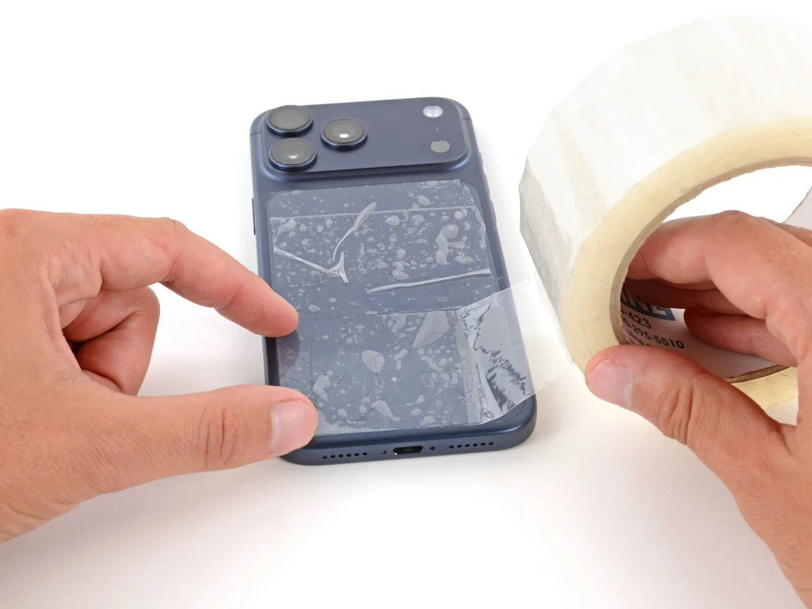
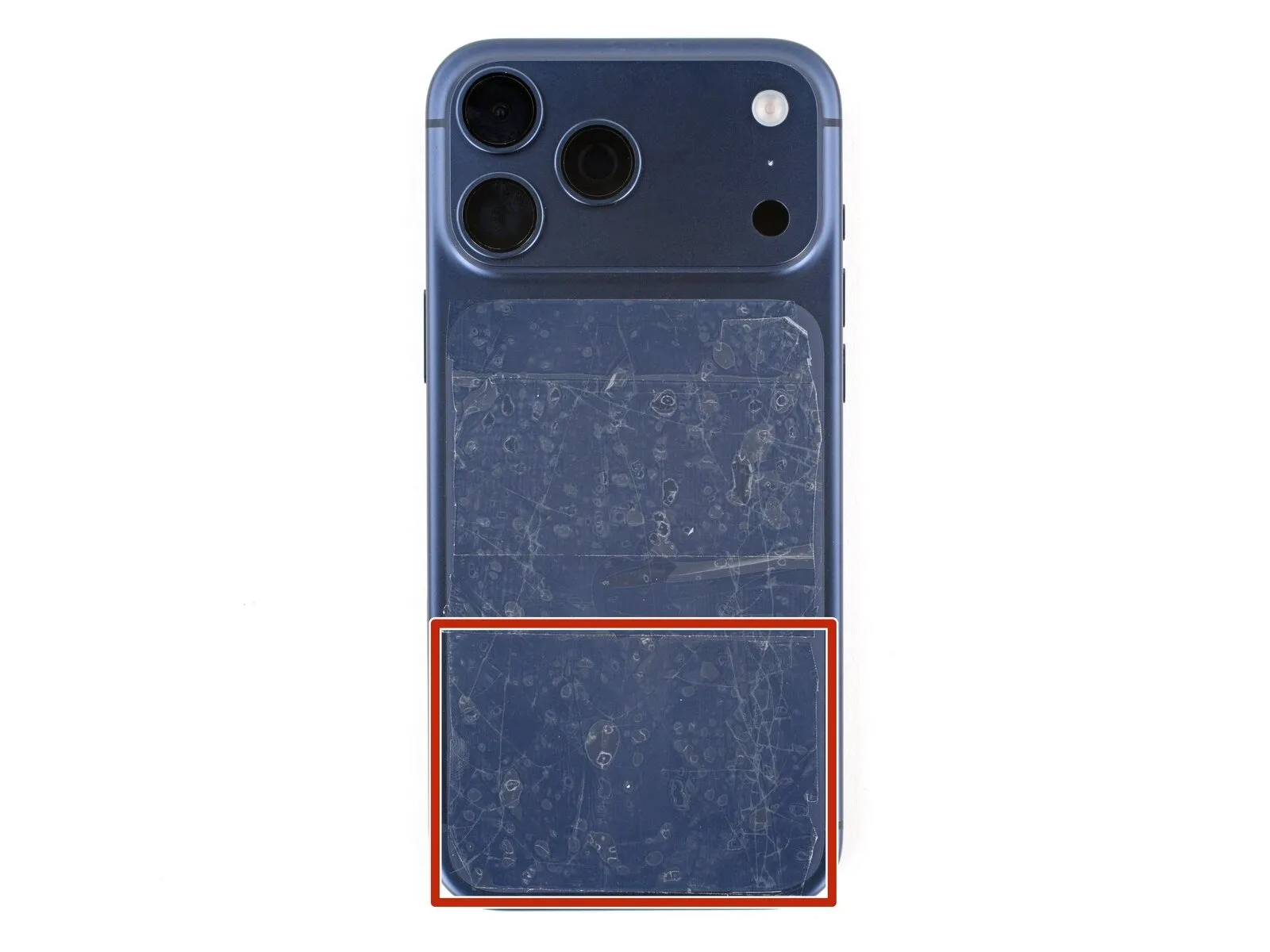
- To mitigate the risk of glass dispersal and facilitate secure suction cup adhesion, affix packing tape strips across the entirety of the damaged glass surface.
- A continuous strip of tape, sufficiently sized to accommodate a suction cup, must be positioned along the lower edge, preventing any overlaps.
- Confine the tape application solely to the glass panel, deliberately avoiding contact with the surrounding frame structure.
- Protect your vision by utilizing safety glasses, as loose glass fragments may become dislodged during the repair procedure.
Step 3 | Remove the pentalobe screws


Employ a P2 pentalobe screwdriver for the disassembly process.The required tool for this step is a P2 pentalobe screwdriver.Two screws, each measuring 7.5 millimeters in length, must be detached.Securely fasten a P2 pentalobe screwdriver to unscrew the fasteners.Positioned on both lateral aspects of the charging port are the two 7.5 mm screws that require removal.
Step 4 | Heat the bottom edge
- The rear glass assembly is secured to the device's frame via an adhesive substance.
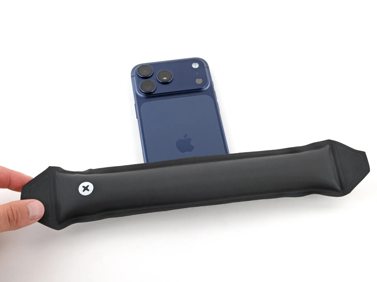
- Employing a device such as an iOpener, apply heat to the lower edge of the rear glass for a duration of 120 seconds.As an alternative method, a standard hair dryer or heat gun can be utilized to warm the rear glass until it reaches a temperature just beyond comfortable touch.Adhering to the provided instructions is critical when using a heat gun, as incorrect application may result in damage to the wireless charging component and/or the battery.
- Applying heat to the adhesive softens it, facilitating the separation of the back glass from the frame.
- The softening effect of heat allows for a simpler disassembly process.
Step 5 | Apply a suction handle
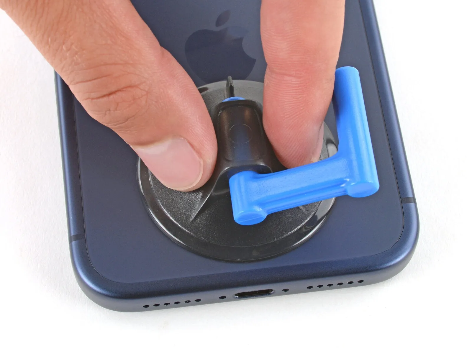
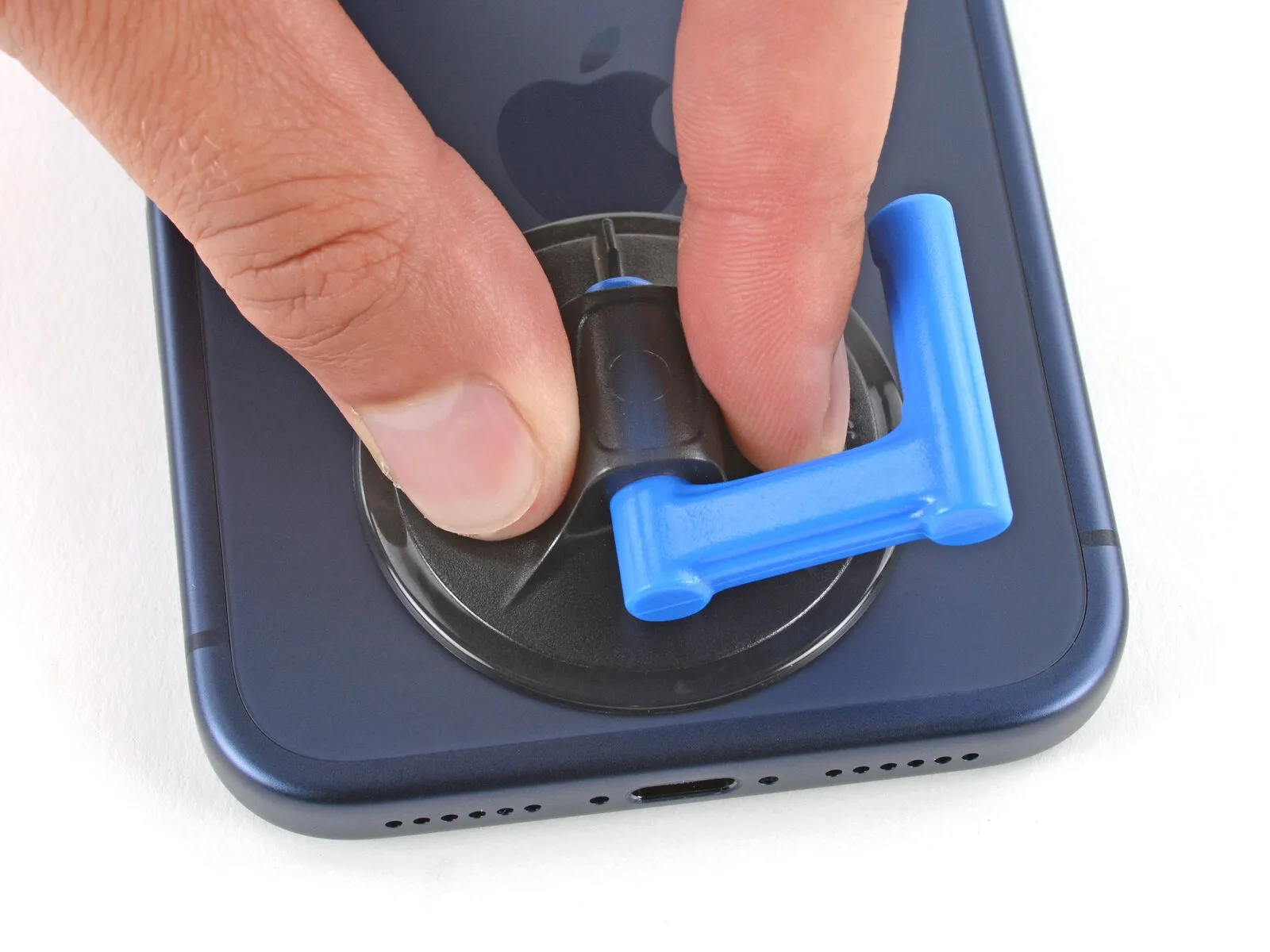
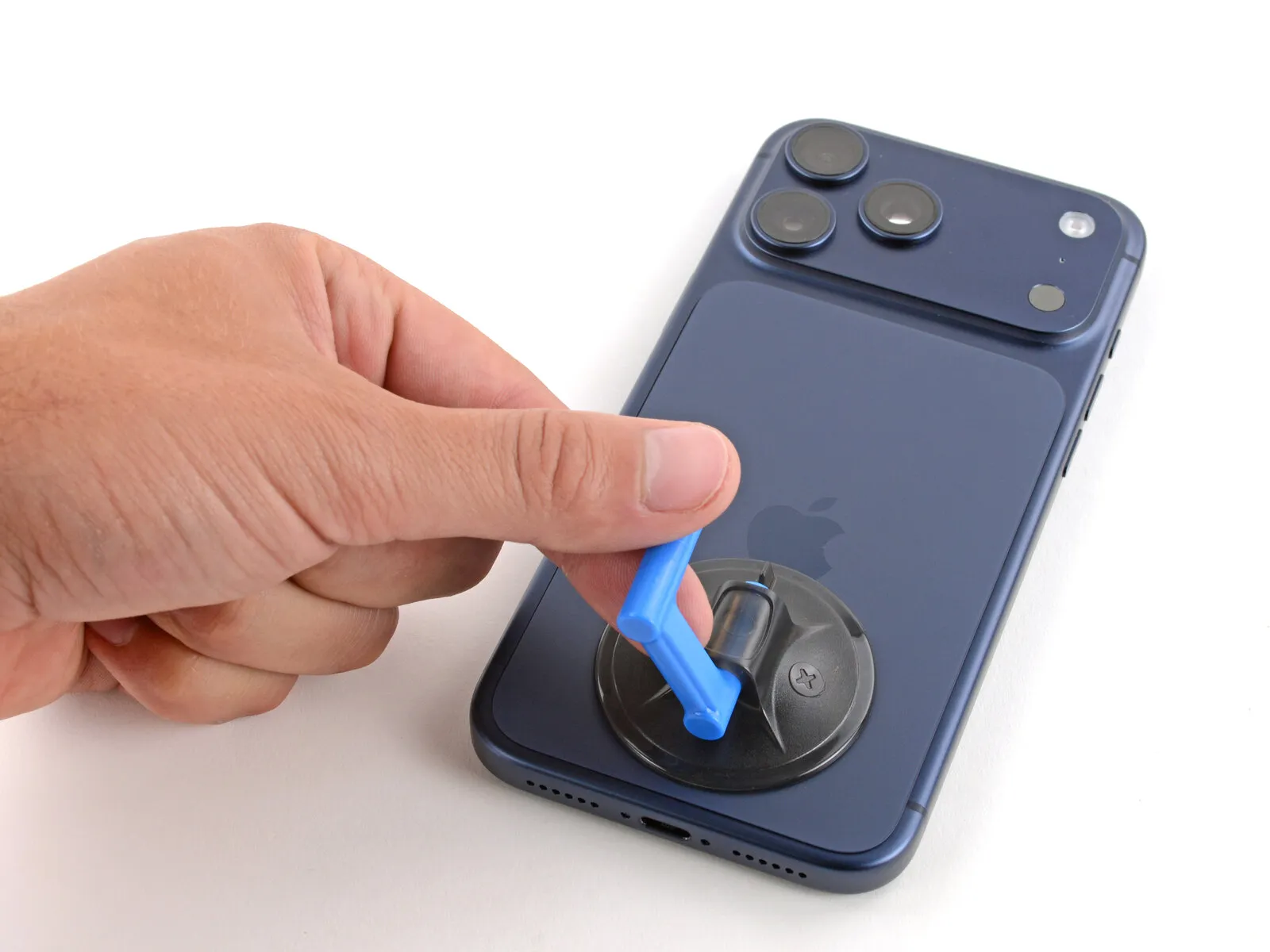
Secure a suction handle firmly against the lower perimeter of the rear glass panel, positioning it as near the edge as feasible.The placement of the suction handle should prioritize proximity to the edge to maximize grip and leverage.Utilize a suction handle to establish a secure hold on the lower edge of the back glass.For optimal effectiveness, position the suction handle at the bottom edge of the rear glass, maintaining close contact with the edge.
Step 6 | Insert an opening pick

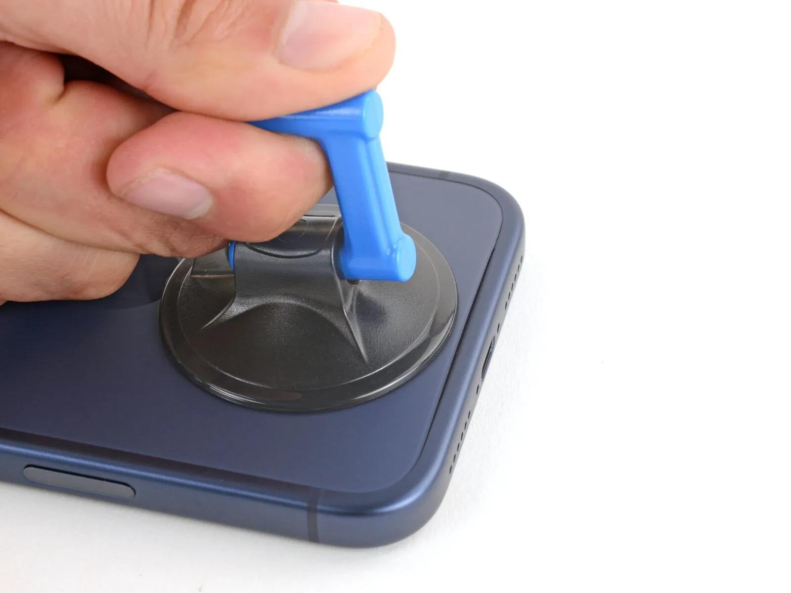

- Exert a firm and continuous pressure on the suction handle to generate separation between the rear glass component and the device's structural frame.Should initial attempts prove unsuccessful, supplemental heat application may be necessary before retrying the separation process.
- To initiate the separation, position the pointed end of an opening tool within the newly formed space.Consistent and robust pressure on the suction handle is crucial for achieving the desired separation.Reheating the adhesive may be required to facilitate the separation of the rear glass from the frame's structure.
- Employing an opening pick, carefully insert its tip into the created space to further the separation.
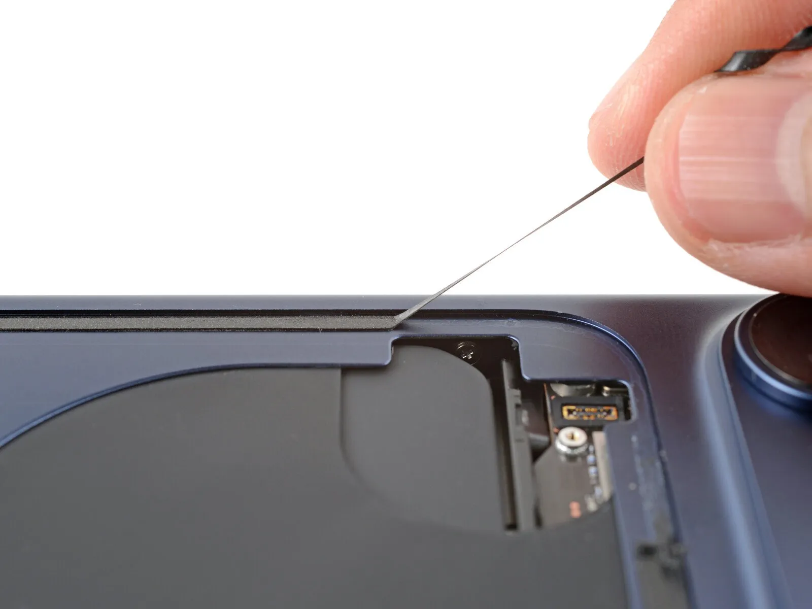
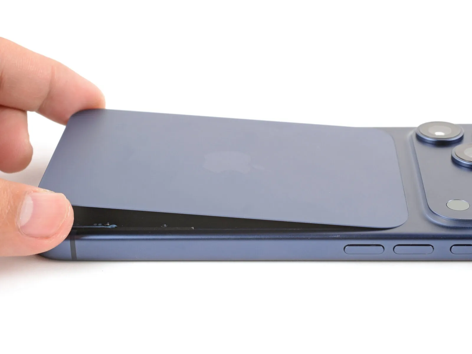
Step 7 | Separate the adhesive
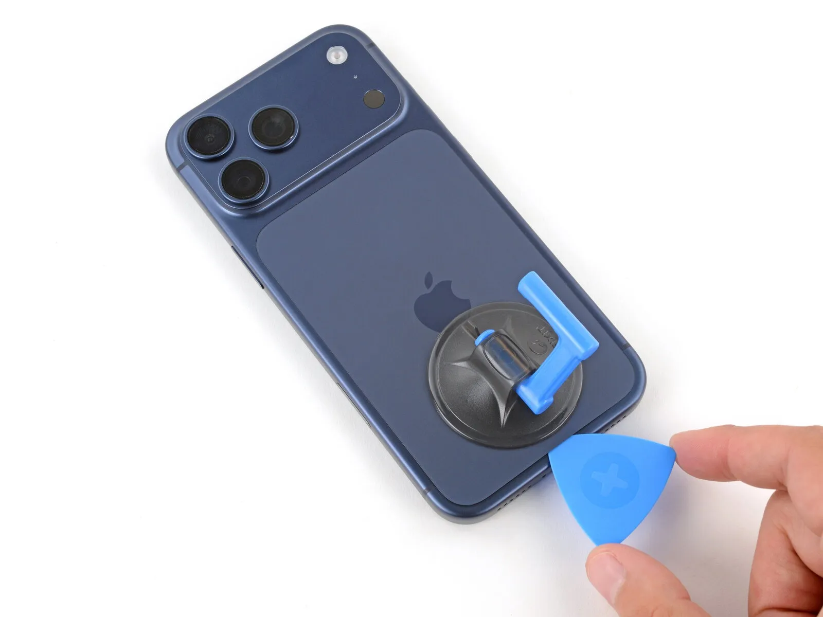
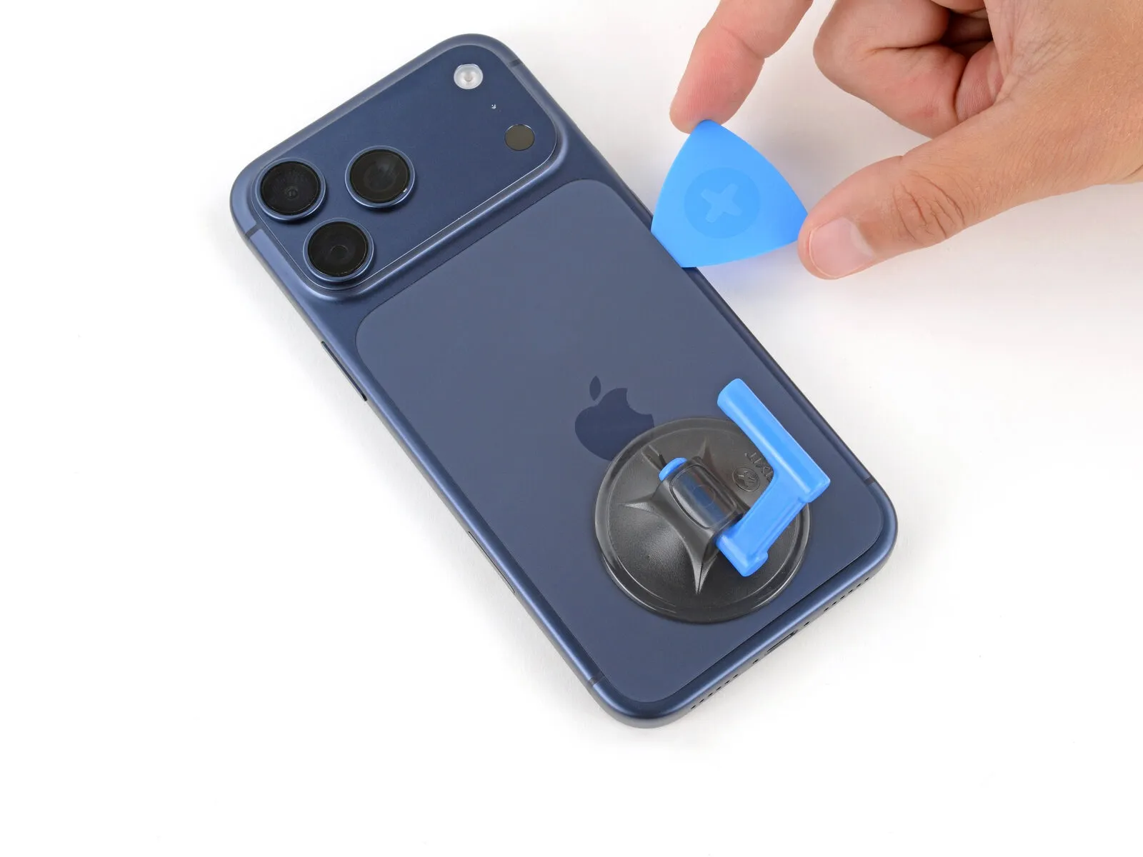

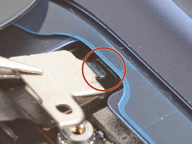
- Utilize a separation tool to carefully work around the edges of the rear glass, releasing the adhesive bond completely.
- Position the separation tool just beneath the upper portion of the left side of the back glass to prevent potential harm to the wireless charging cable.
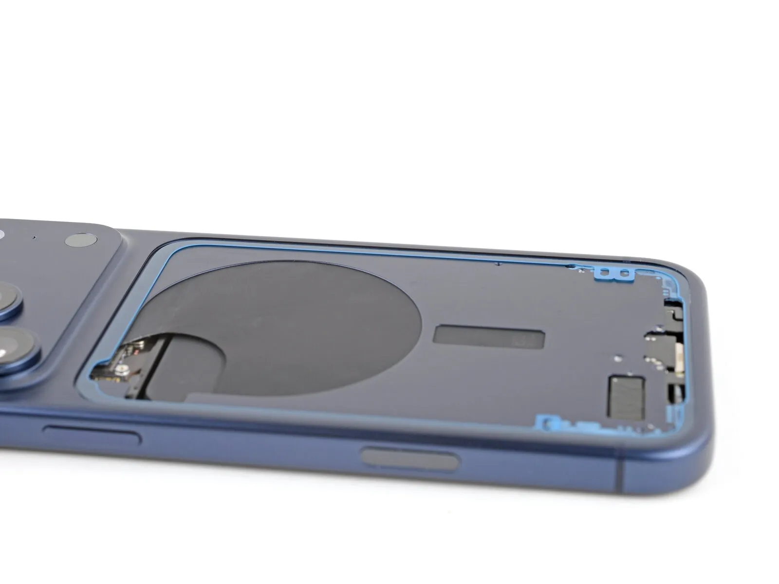
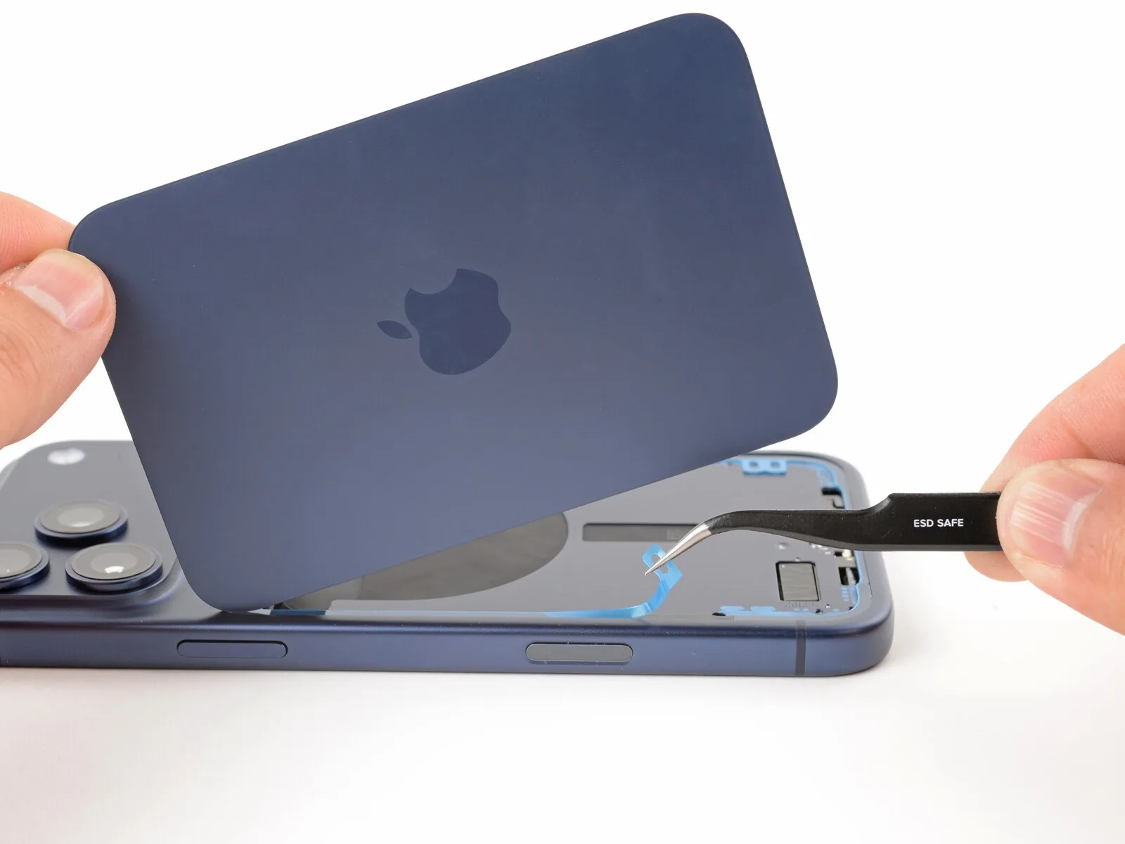
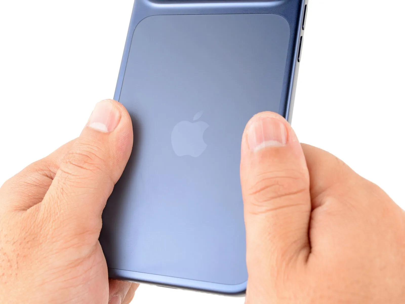
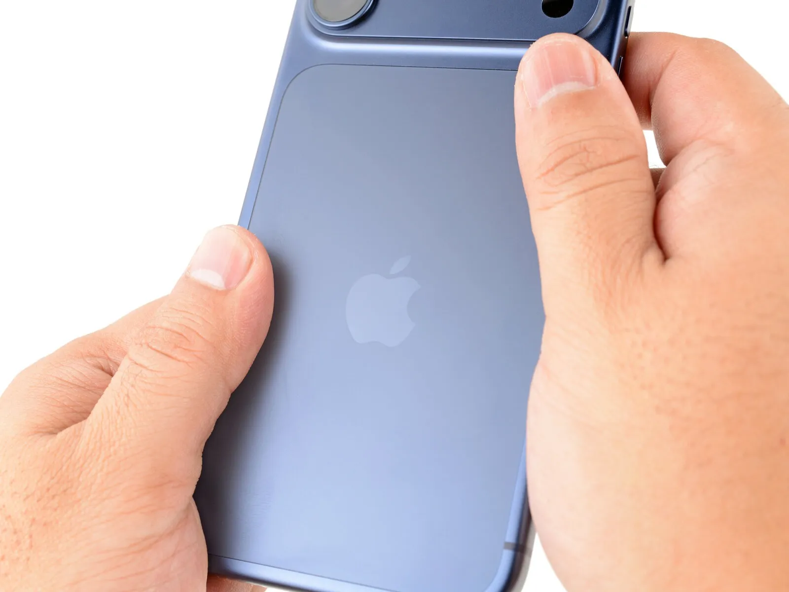
Step 8 | Prop up the back glass


Ensure the rear glass component is fully detached from the device's surrounding structure; persistent adhesion suggests a need to revisit the edges for complete adhesive removal.
Invert the detached back glass, positioning it over the left lateral edge, and utilize the specialized suction handle to provide temporary support.The suction handle, a tool designed for gripping smooth surfaces, facilitates maintaining the glass's position during subsequent repair steps.As an alternative method for stabilization, carefully place the glass horizontally across the left side of the device.
This alternative placement provides a stable base for the rear glass while allowing access to other components.
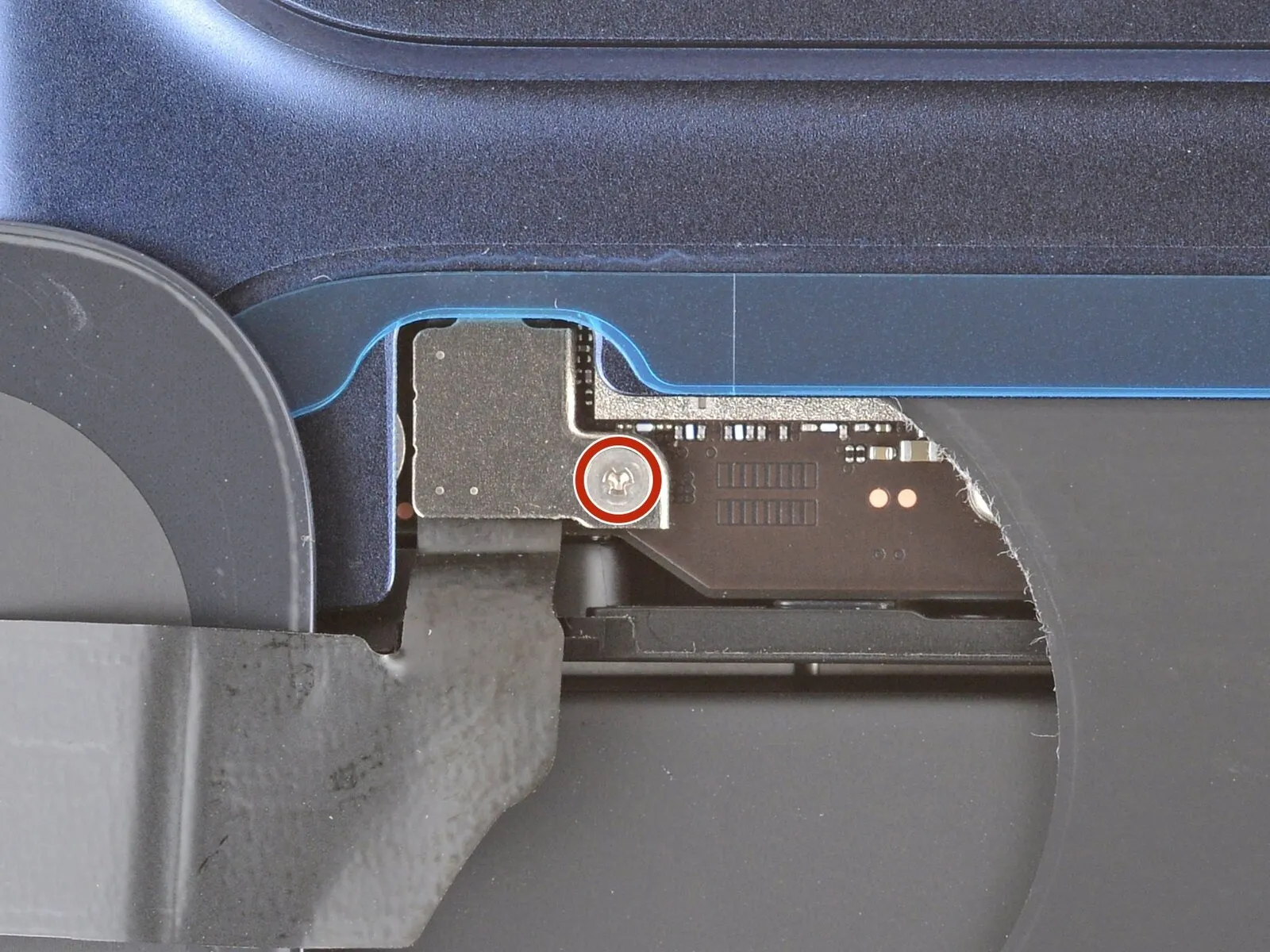
Step 9 | Remove the cover screw
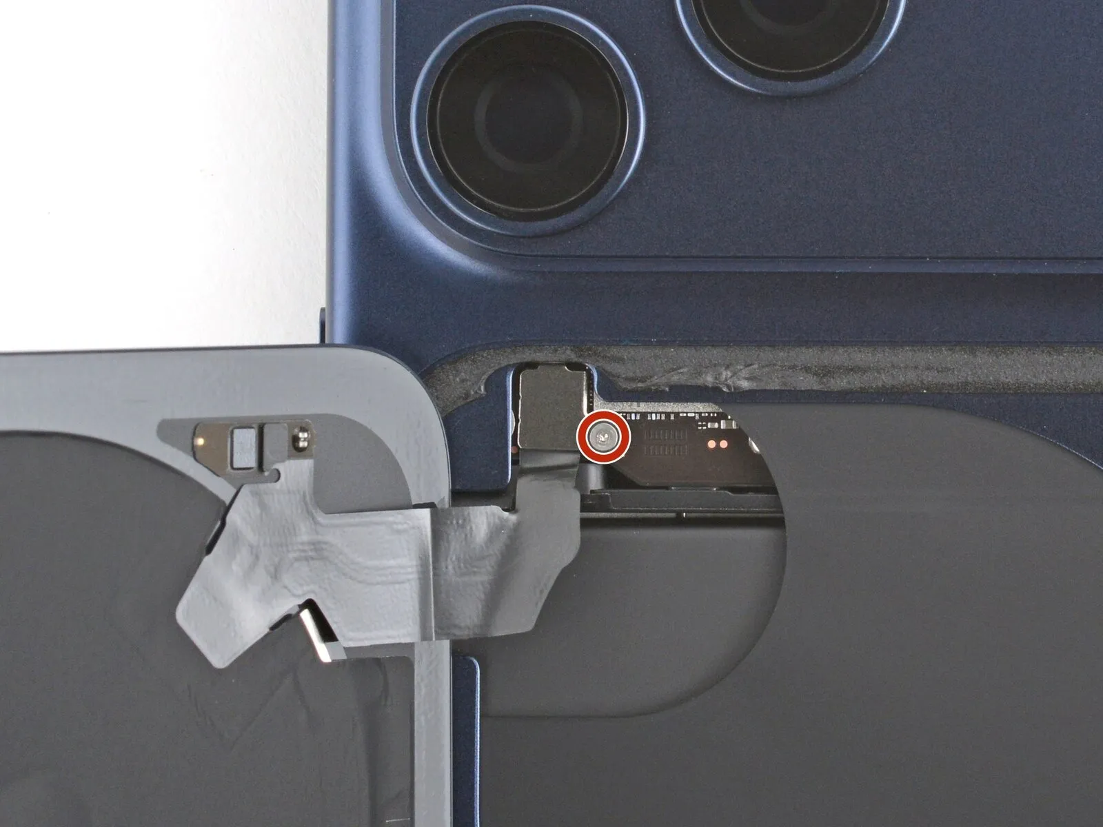
Exercise extreme care to prevent injury or harm.Avoid contact between your repair implements and the vulnerable battery.
- Employ a specialized tri-point screwdriver, specifically a Y000 type, for the next step.A single screw, measuring precisely 1.0 millimeters in length, must be unscrewed.This screw's purpose is to fasten the wireless charging connector cover in place.Damage to the battery may occur if proper precautions are not taken during this procedure.
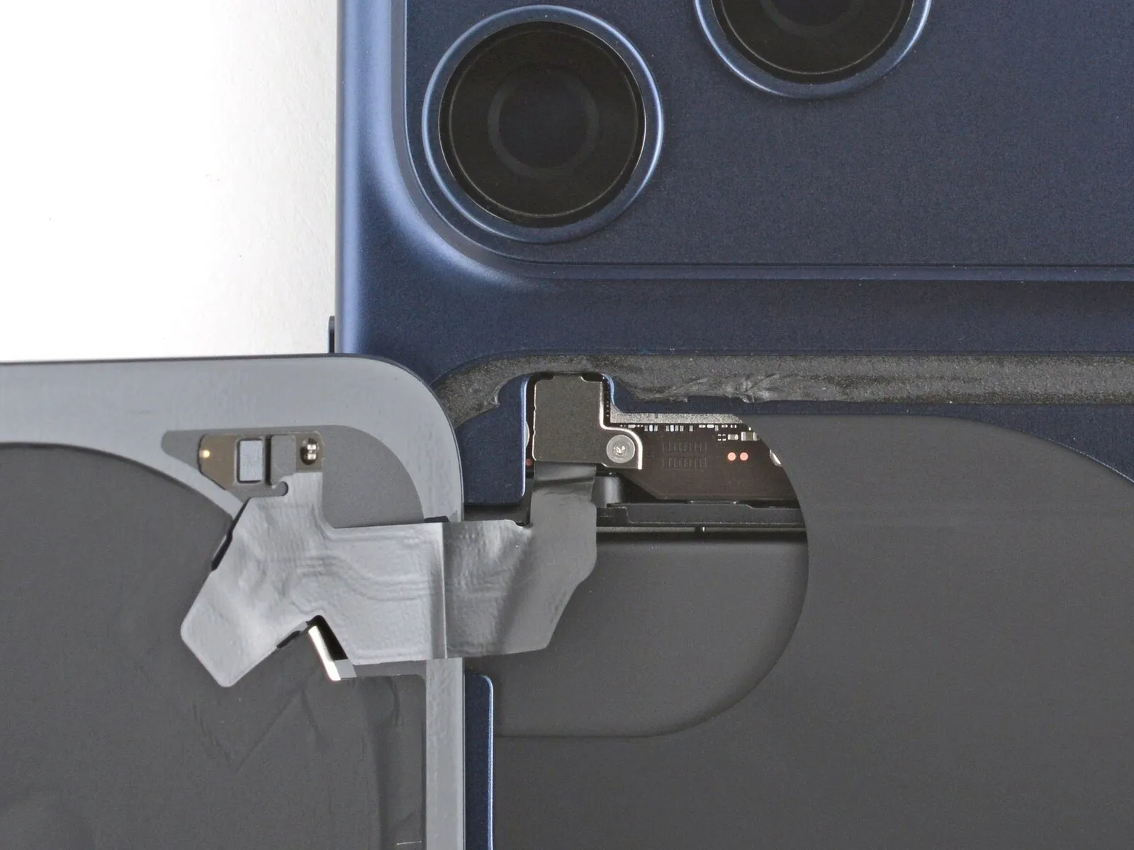
Step 10 | Remove the cover

Detach the protective housing.
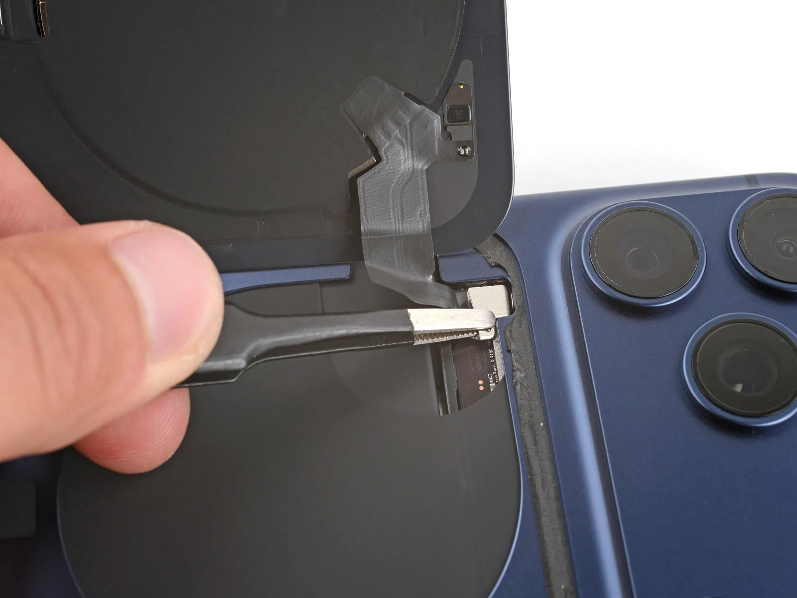
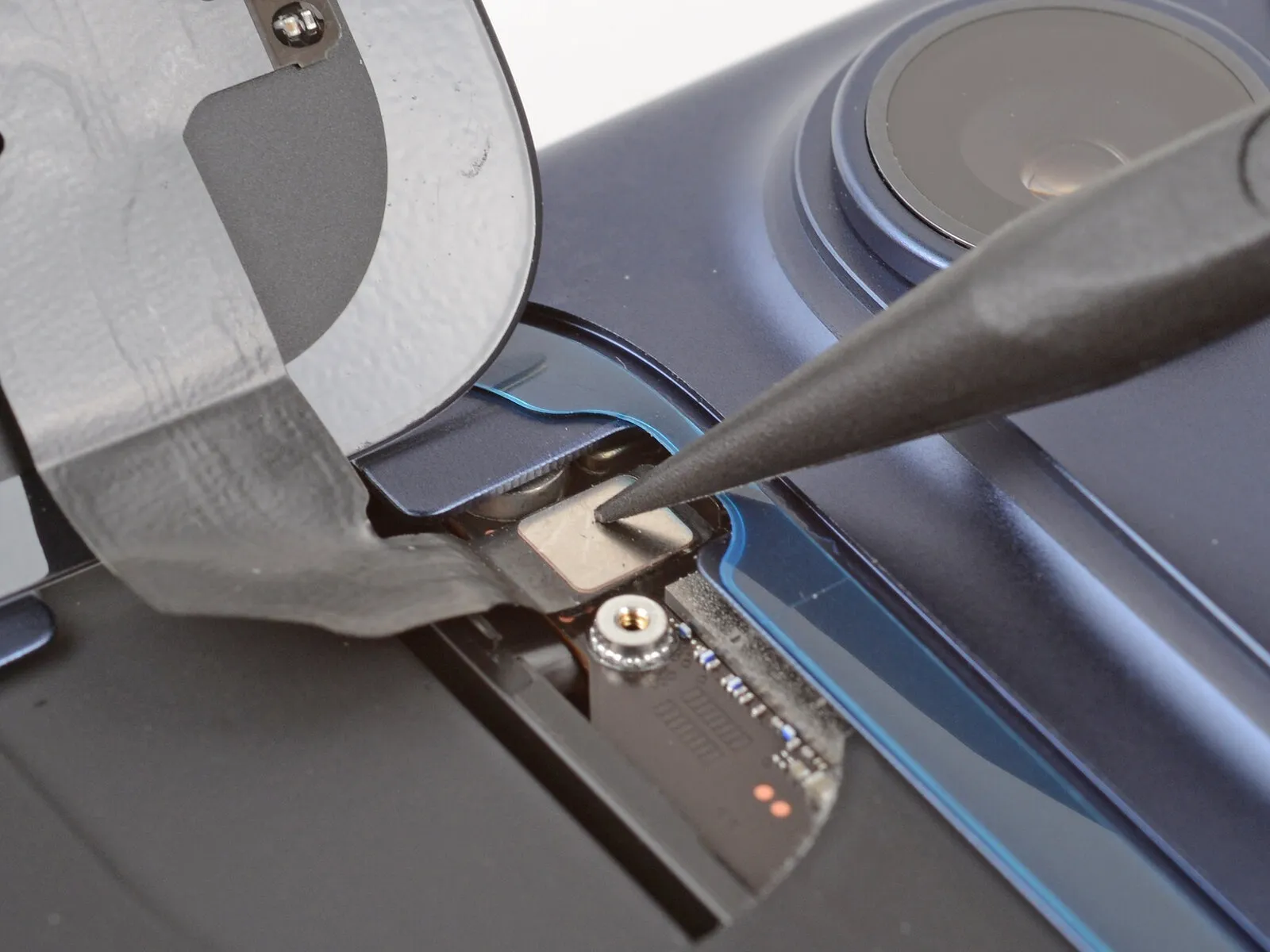
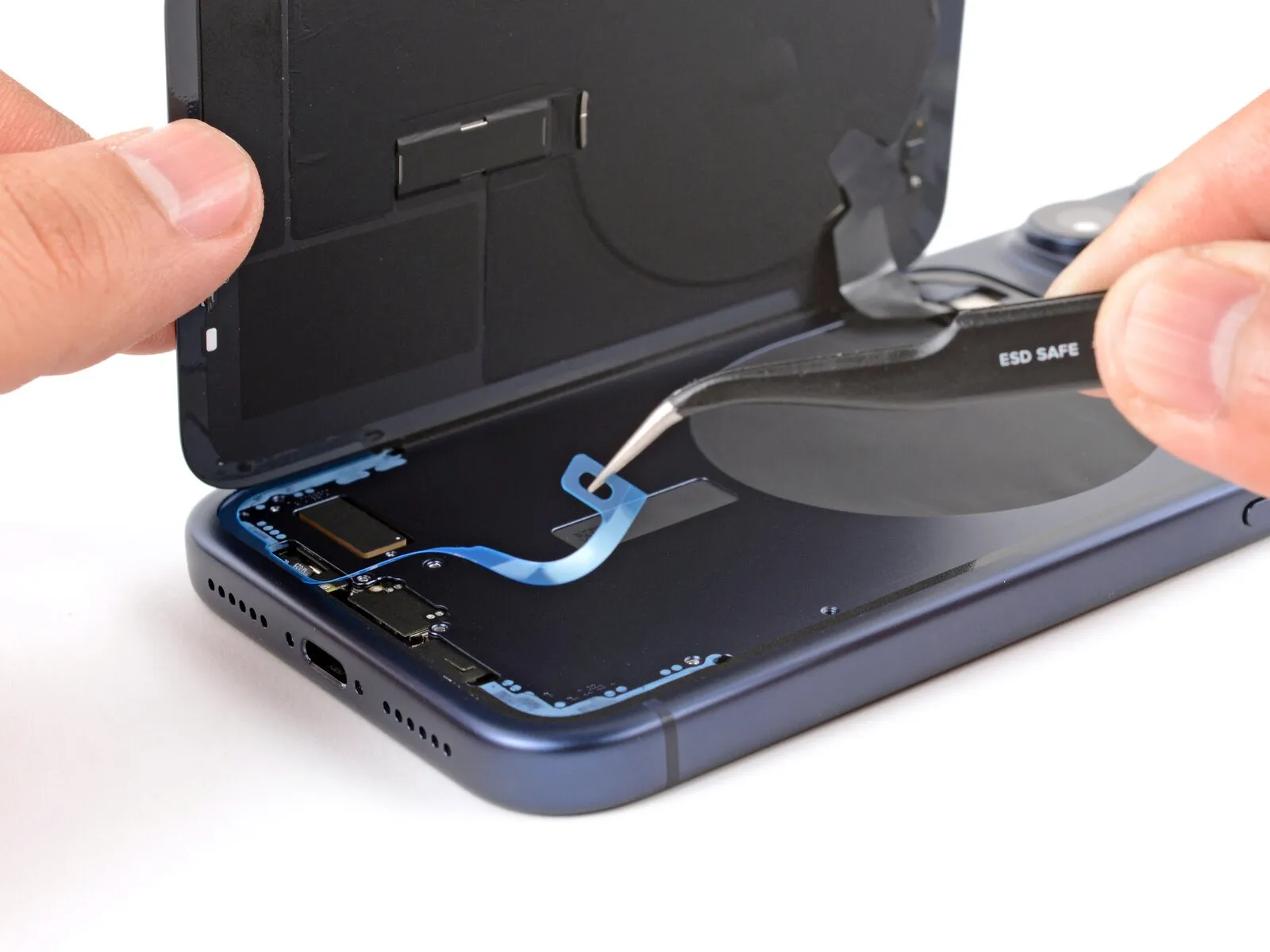
Step 11 | Disconnect the back glass

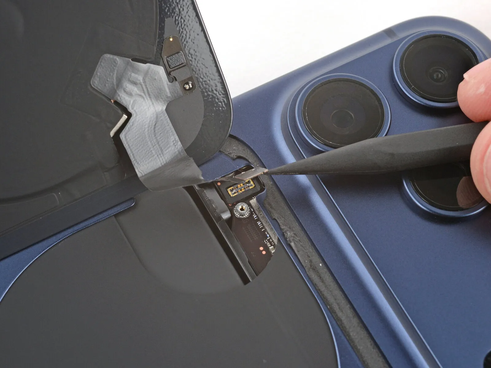
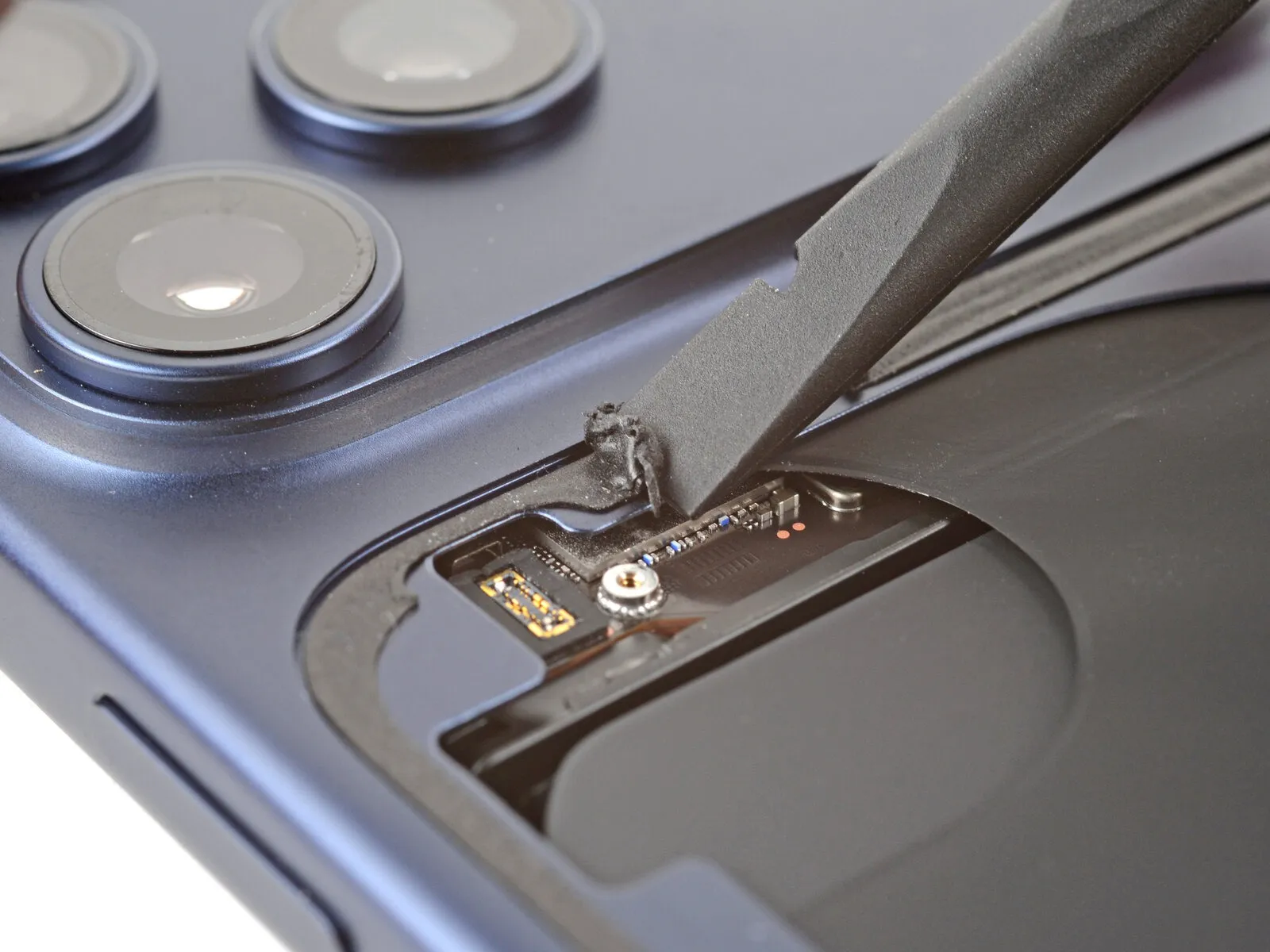
- Employing the tip of a spudger, carefully lift and detach the wireless charging press connector.The wireless charging press connector must be disengaged by utilizing the pointed end of a spudger.
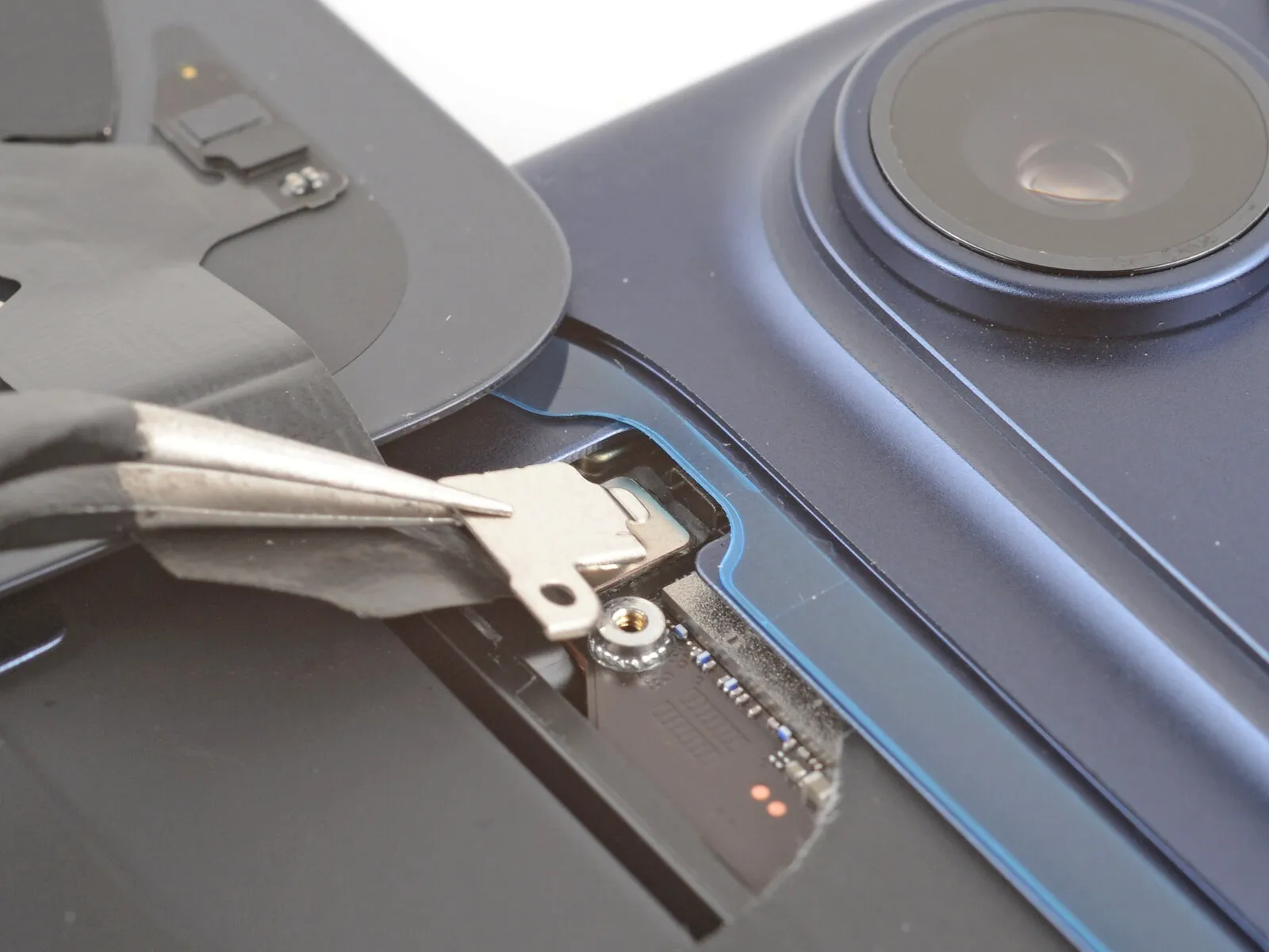
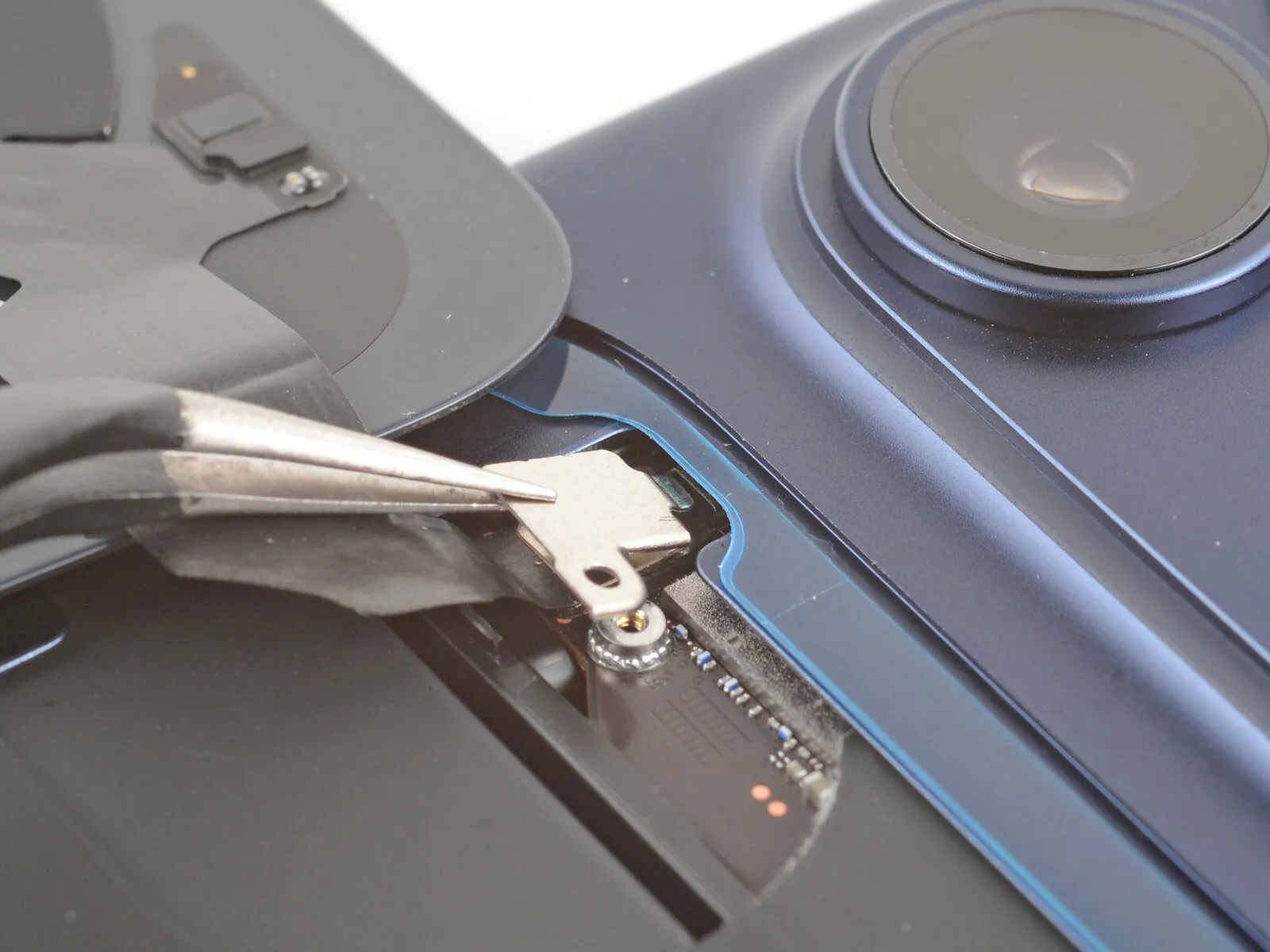
Step 12 | Remove the back glass
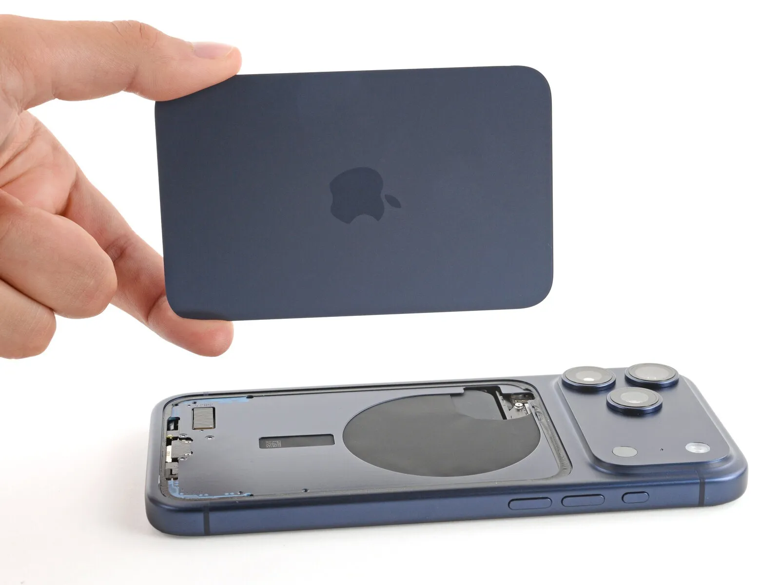
- Detach the rear panel of glass.
Step 13 | Disassembly complete
- Having finished the disassembly process, proceed with the subsequent instructions to reassemble the device.
Although photographic representations of the reassembly process might exhibit slight variations based on the specific iPhone variant, the outlined procedure remains accurate for all models.
Step 14 | Remove the leftover adhesive
- Employ blunt-nose tweezers, or manually, to detach sizable adhesive fragments from the frame's surface.A spudger is suitable for carefully scraping away the remaining adhesive residue adhered to the frame.Persistent adhesive can be softened by applying warmth with a hair dryer or heat gun, then attempt removal again.
To facilitate adhesive separation, utilize blunt-nosed tweezers or your fingertips for the initial removal of larger sections.Employing a spudger allows for precise scraping of the adhesive residue that remains on the frame's surface.When encountering difficult-to-remove adhesive, applying heat with a hair dryer or heat gun can aid in its softening and subsequent removal.
For the purpose of removing substantial adhesive portions, blunt-nose tweezers or direct manual manipulation are appropriate, followed by a spudger for residue.
Step 15 | Orient the replacement adhesive

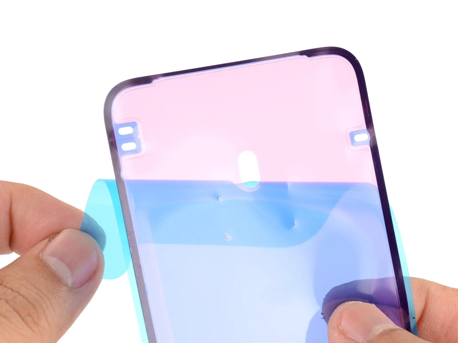
- To ascertain the correct positioning of the adhesive layer, place it upon the frame's surface, ensuring no protective liners are removed.
Employ structural elements, such as the rear glass connector indentation, to guide the adhesive's alignment.
Step 16 | Apply the replacement adhesive
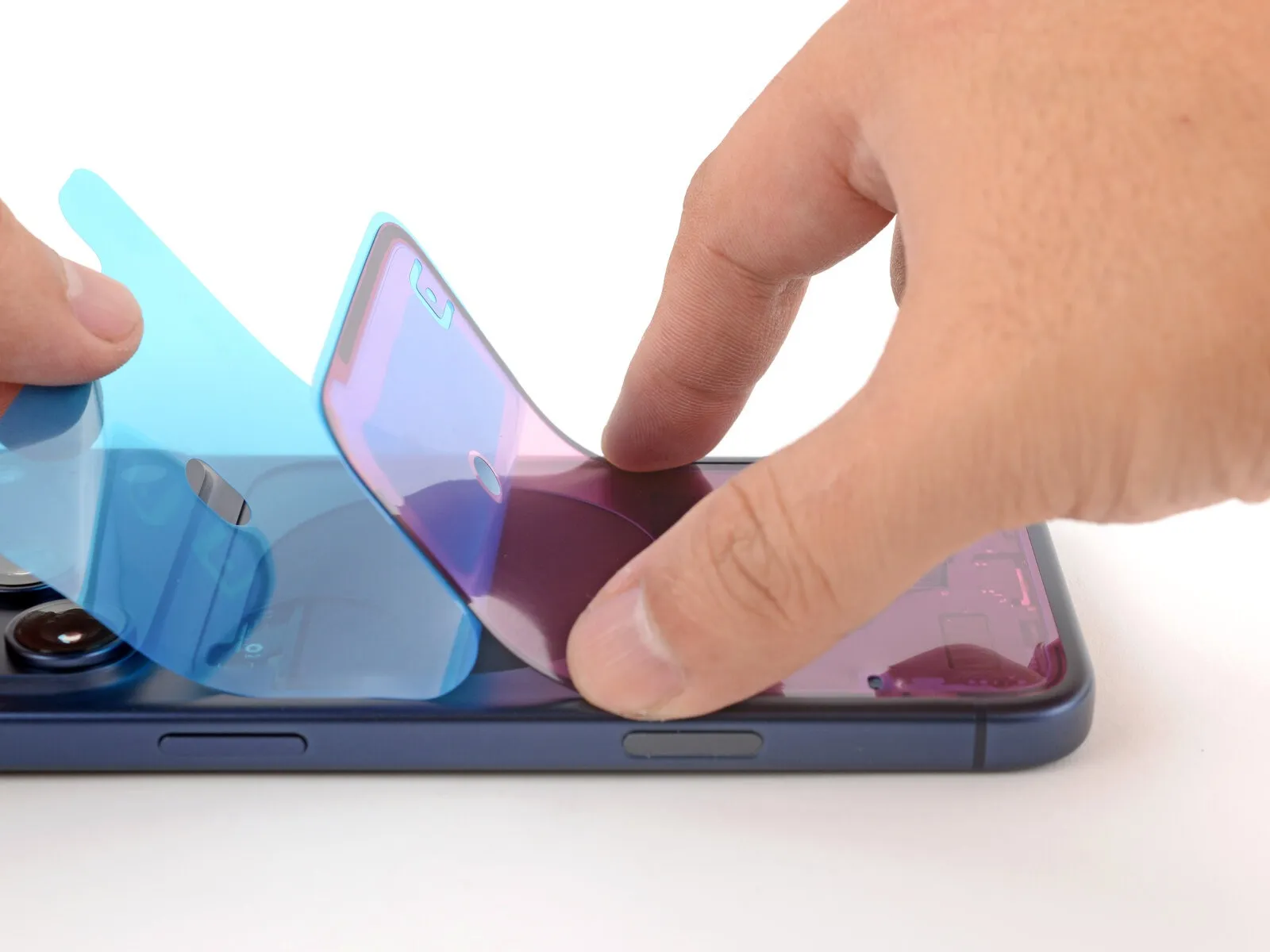
- To reveal a portion of the adhesive, carefully lift the corner tab of the adhesive sheet's liner and remove it, exposing approximately one-third of the adhesive surface.
- Due to its high tack, the revealed adhesive should remain free from contact with other surfaces until it is properly positioned on the frame.
- Should your adhesive contain several liners, remove only the uppermost liner to expose the side intended for bonding to the frame.
Step 17


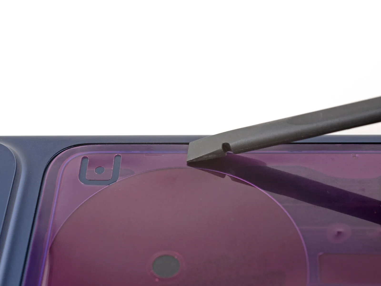
- Ensure precise positioning of the adhesive strip's visible perimeter before applying pressure to the frame.
- After the adhesive secures, repositioning is impossible; minor misalignments can be corrected by carefully drawing the extended borders toward the frame's surface.
- Should the adhesive develop folds or distortions, discard it and initiate the process anew with a replacement strip.
- In the absence of additional adhesive strips, the iPhone can be reassembled and utilized without them, acknowledging that its water resistance will be diminished until a replacement is installed.
Step 18
- Employ a spudger to apply pressure to the adhesive securing the perimeter of the device.
- Exercise caution to prevent excessive force, which may cause the adhesive to distort or extend beyond its intended shape.
Step 19

- To detach the extensive front adhesive backing, grasp the pull tab, typically located at a corner, and carefully remove it.
- Should the adhesive separate from the device alongside the liner during removal, apply downward pressure with a spudger tip to secure it.
- Remaining perimeter liners serve to protect the adhesive during reassembly; postpone their removal until later.
Step 20 | Install the back glass
- Arrange the rear glass panel to facilitate a convenient reconnection process.
- Employ a fingertip or a specialized spudger tool to apply pressure and secure the back glass connector to the logic board.
Step 21
- Ensure the connector cover is positioned correctly, aligning the upper tab beneath the corresponding edge protrusion.
Step 22
- Employ a specialized tri-point screwdriver, specifically a Y000 type, for the installation process.A screw measuring precisely 1.0 millimeters in length is required for this step.The designated fastener serves the purpose of securing the connector cover in place.Ensure the tri-point Y000 screwdriver is utilized to avoid damage to the screw head.Properly fastening the connector cover with the 1.0 mm screw maintains the integrity of the assembly.
Step 23
- Securely grasp the rear glass panel with one hand, exercising caution to prevent undue stress on the connecting cable.
Utilize a finger or tweezers to carefully remove any residual liners, fully revealing the adhesive sealant around the edges.
Step 24

- Position the superior border of the rear glass so that it corresponds with the designated opening, then carefully set it down.
Step 25

- Employing a secure grip, apply consistent pressure along the complete edge of the rear glass panel using your hands.
Step 26 | Install the pentalobe screws
- Employ a P2 pentalobe screwdriver for the installation process.The two screws, each measuring 7.5 millimeters in length, require installation.These screws are positioned on both lateral aspects of the charging port.Securely fasten the screws using the specified screwdriver.Proper alignment is essential when installing the 7.5 mm screws adjacent to the charging port.