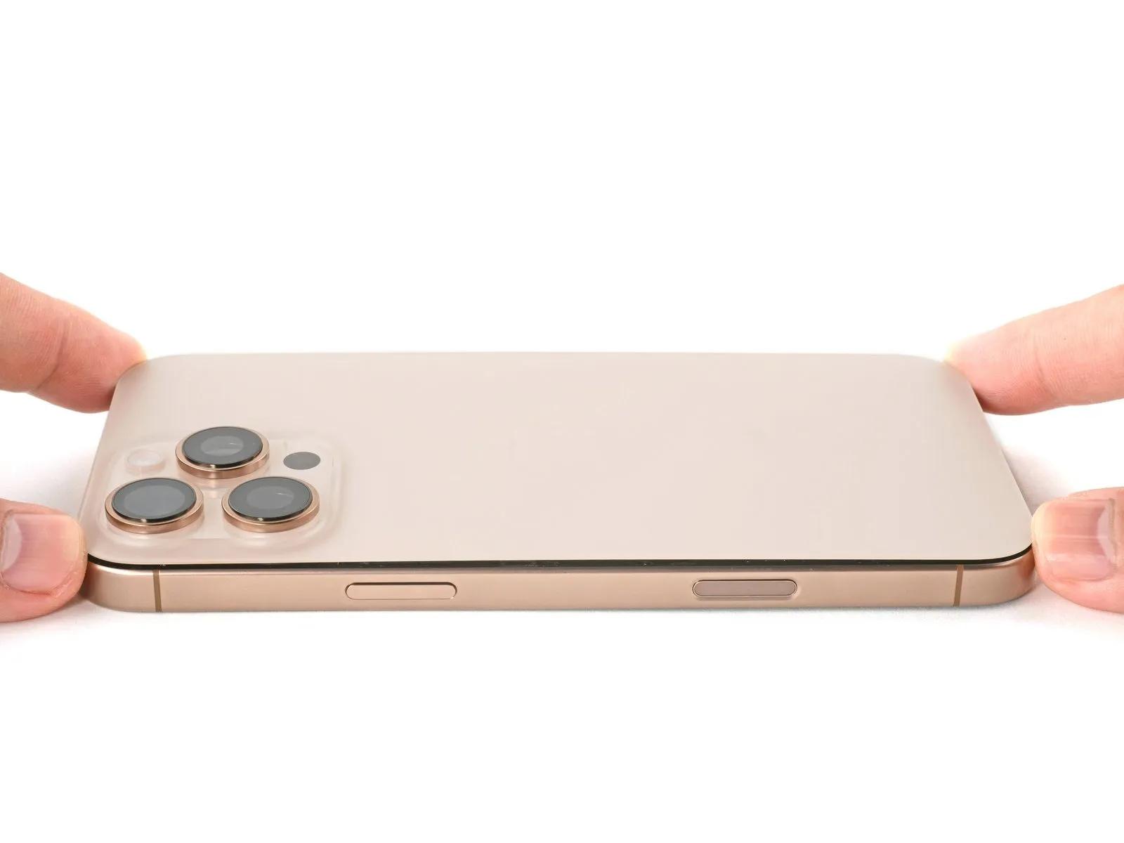
iPhone 16 Pro Max Loudspeaker Replacement
The following instructions detail the procedure for removing and substituting the bottom-firing speaker within an iPhone 16 Pro Max.A diminished or distorted audio output from the iPhone 16 Pro Max's lower speaker often indicates a need for speaker replacement.Malfunctioning loudspeakers can manifest as quiet or distorted sound reproduction through the device's bottom speaker.
To successfully perform this repair, obtaining new adhesive specifically designed for the iPhone's rear glass is essential.The process involves carefully detaching the existing speaker assembly and installing a fresh unit to restore proper audio functionality.Should you experience reduced volume or crackling sounds emanating from the iPhone 16 Pro Max's lower speaker, a replacement is likely required.
- Proper sealing of the rear glass is ensured by utilizing fresh adhesive during the speaker replacement process.
Step 1 | Before you begin
- To mitigate potential safety risks associated with charged lithium-ion cells, permit your iPhone's battery level to decrease to less than 25%.
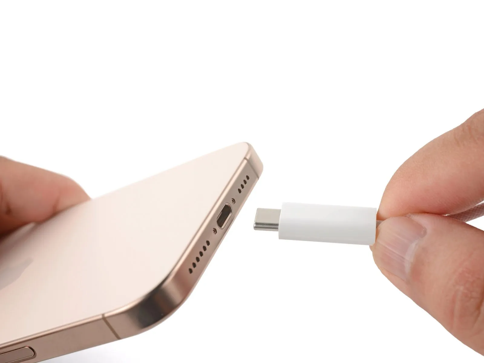
- Disconnect all connected cables from the iPhone device.
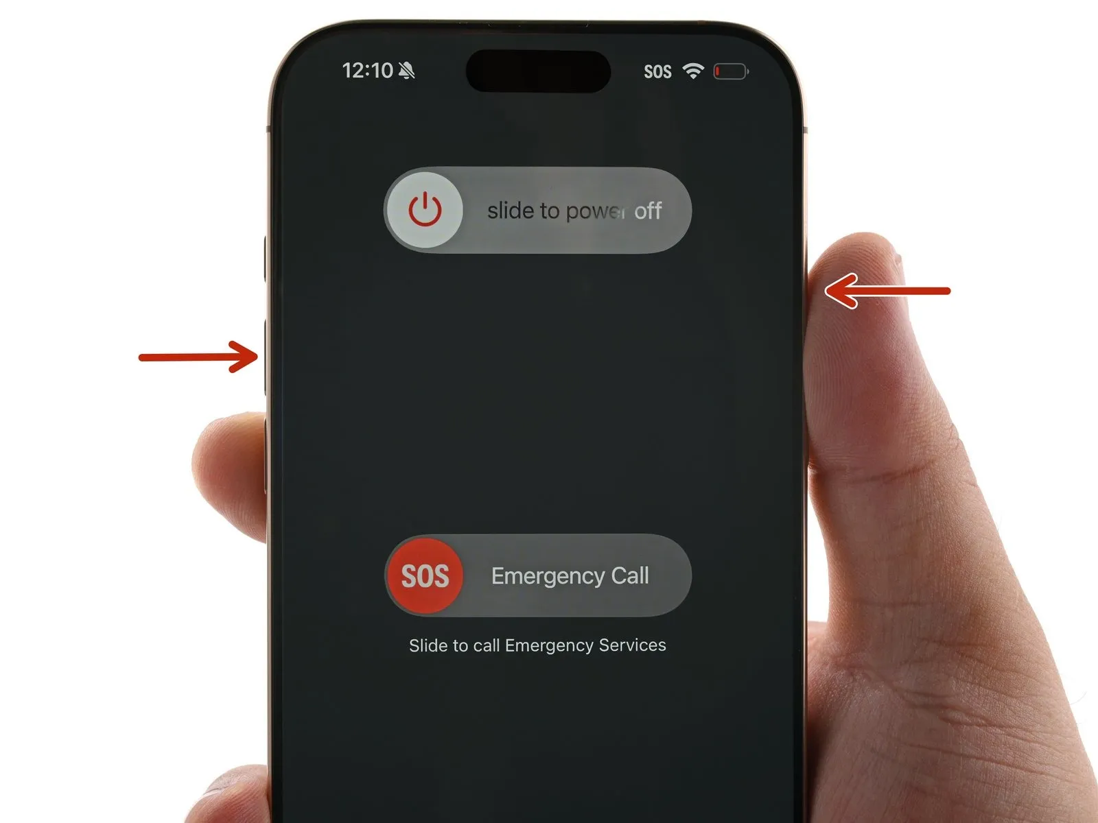
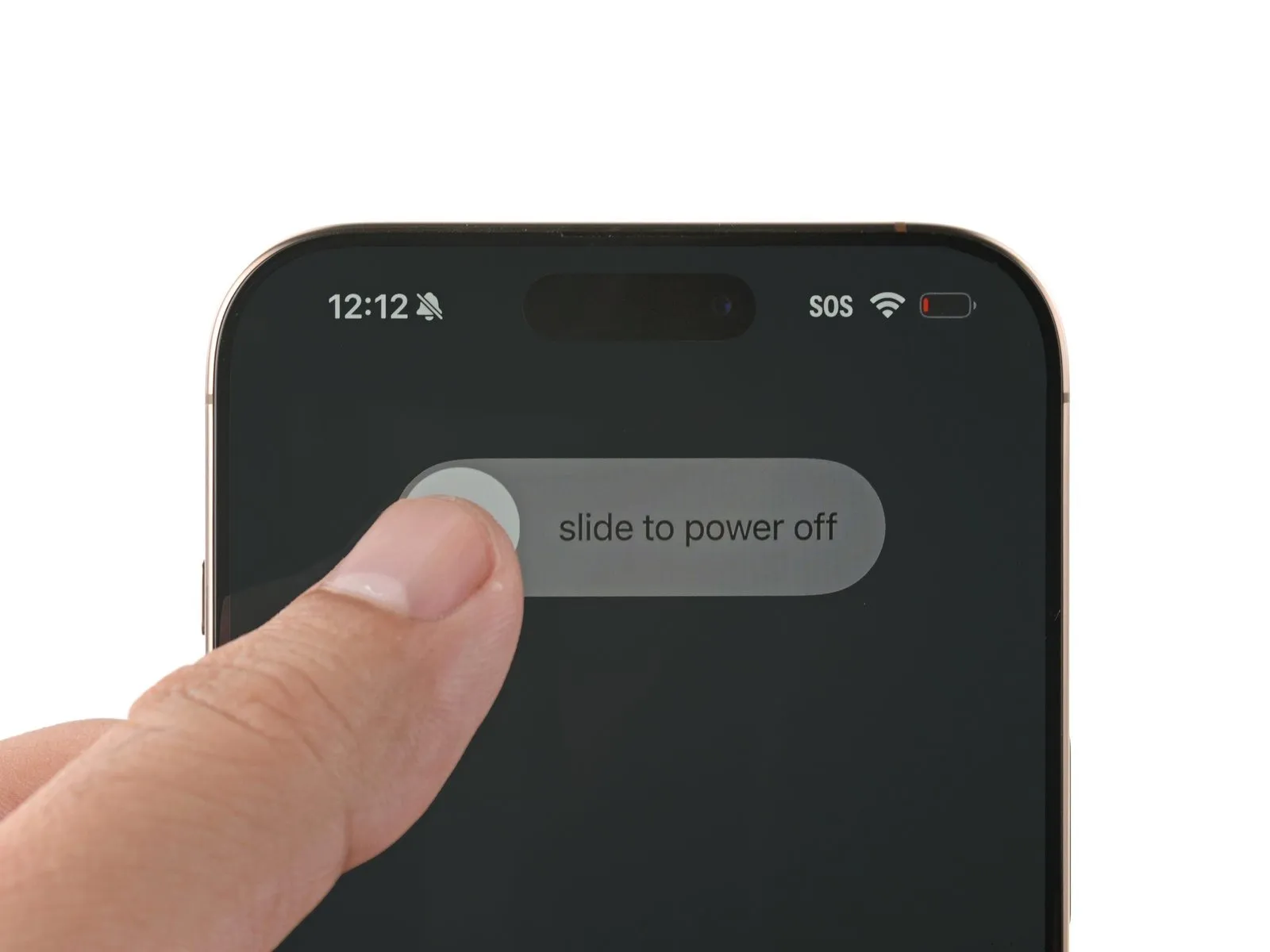
- Simultaneously press and maintain the power button along with either volume button, then utilize a sliding motion to deactivate the iPhone.
Step 2 | Tape over any cracks
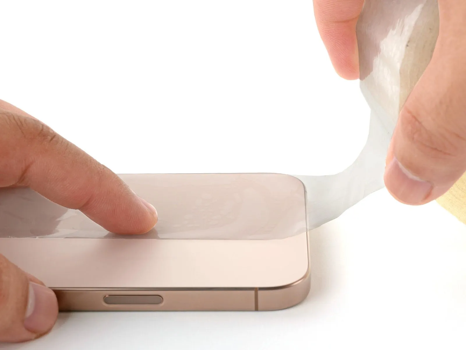
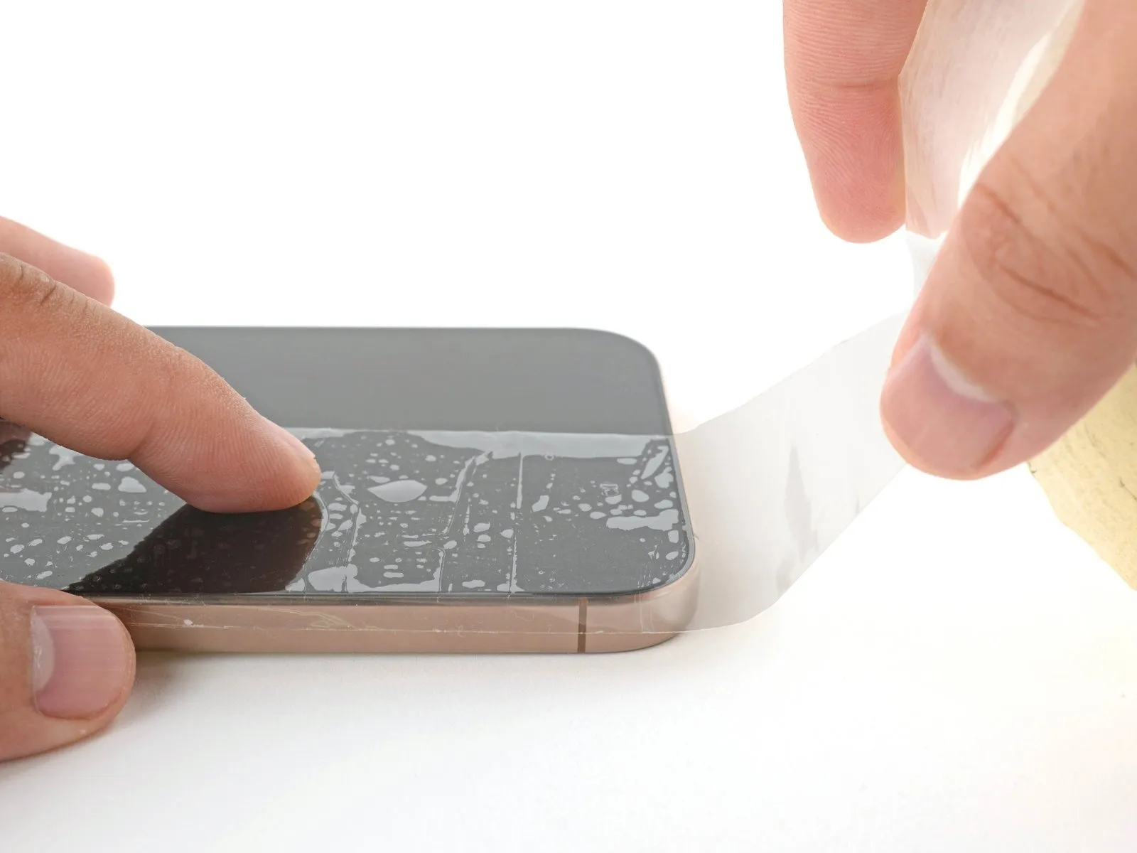
- To prevent injury and facilitate the subsequent separation of components, apply multiple layers of adhesive packing tape across the fractured screen or rear glass surface.
- Confirm the existence of a sufficiently sized, uninterrupted section close to the lower perimeter, suitable for secure adhesion of a suction cup.
Step 3 | Remove the pentalobe screws
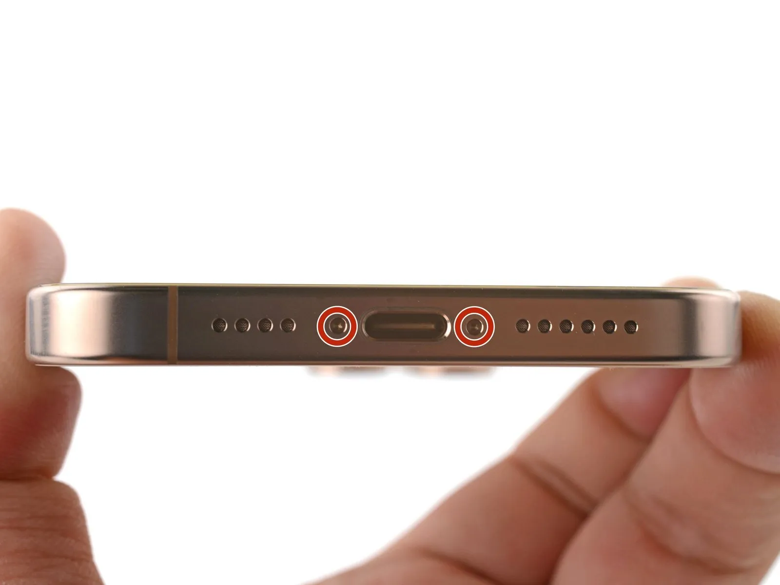

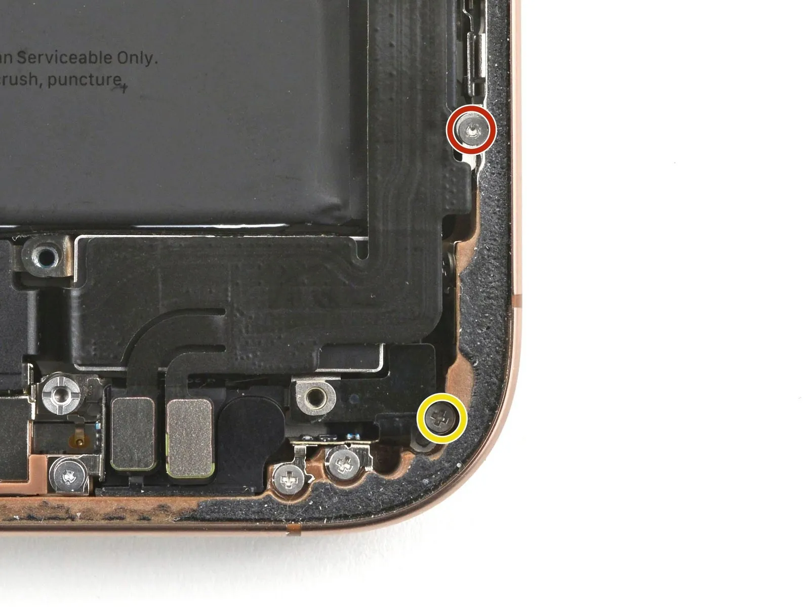
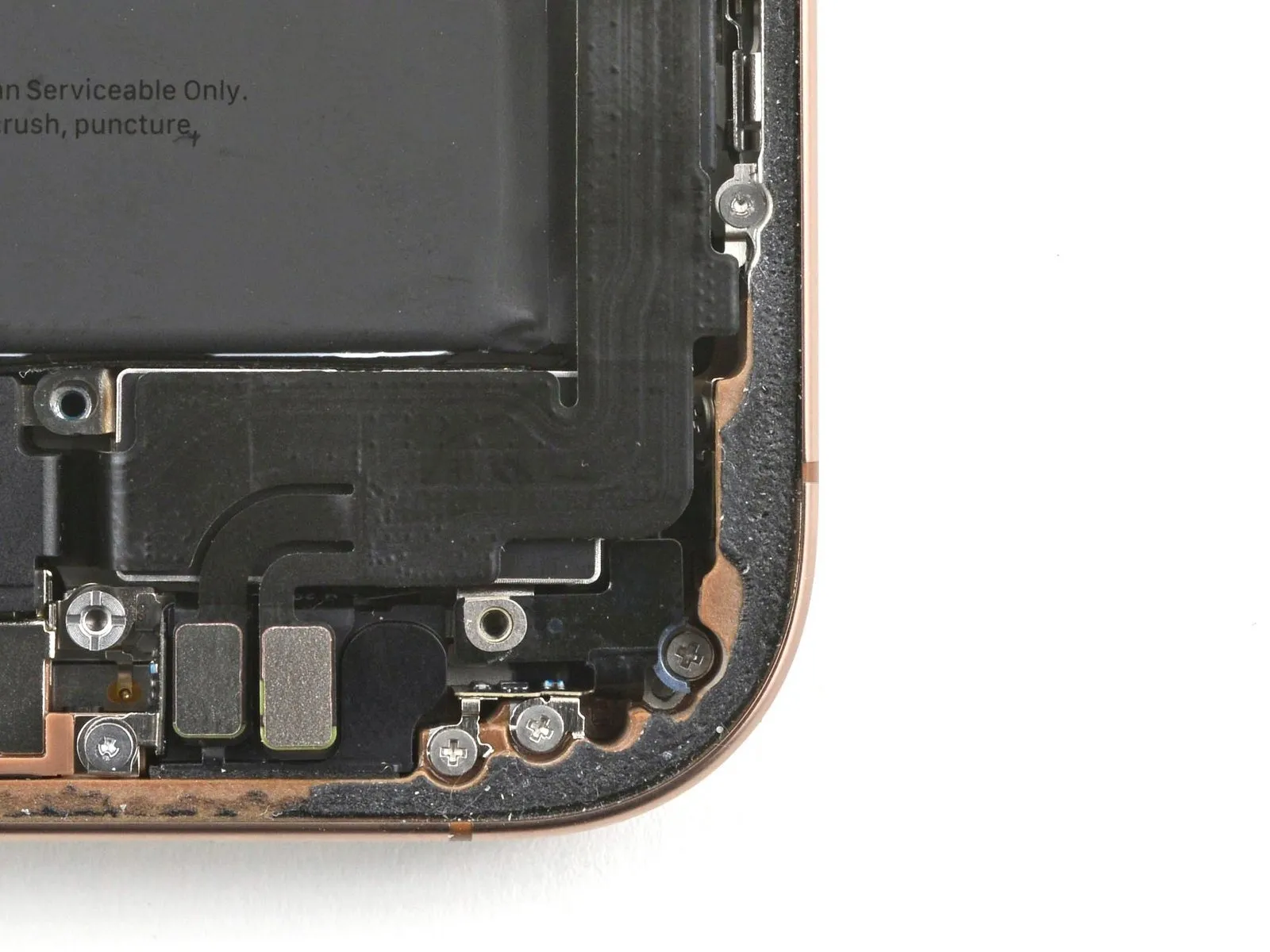
Employ a P2 pentalobe driver to detach the two screws, each measuring 7.4 mm in length, which are situated on both sides of the charging port.The two fasteners securing the device near the charge port require removal using a specialized P2 pentalobe driver tool.To access the components adjacent to the charging port, a P2 pentalobe driver is necessary for unscrewing the two 7.4 mm screws.
Step 4 | Mark your opening picks


- Caution is advised: Overly deep insertion of a spudger can result in device harm.To mitigate potential damage, implement the following procedure to indicate your spudger's safe insertion depth.
- Using a permanent marker, precisely note a point on the spudger's tip, located 3 millimeters from the very end.
- This measurement of 3 mm establishes a limit to prevent excessive penetration.For enhanced precision, consider marking additional corners of the spudger with varying distances.As an alternative method, securely affix a coin to the spudger's tip, ensuring the coin's edge is precisely 3 mm from the point.
- The coin serves as a visual indicator of the maximum safe insertion distance.
- Adherence to this marking or alternative method will help avoid unintended damage to the device's internal components.
Step 5 | Create a gap using a suction handle
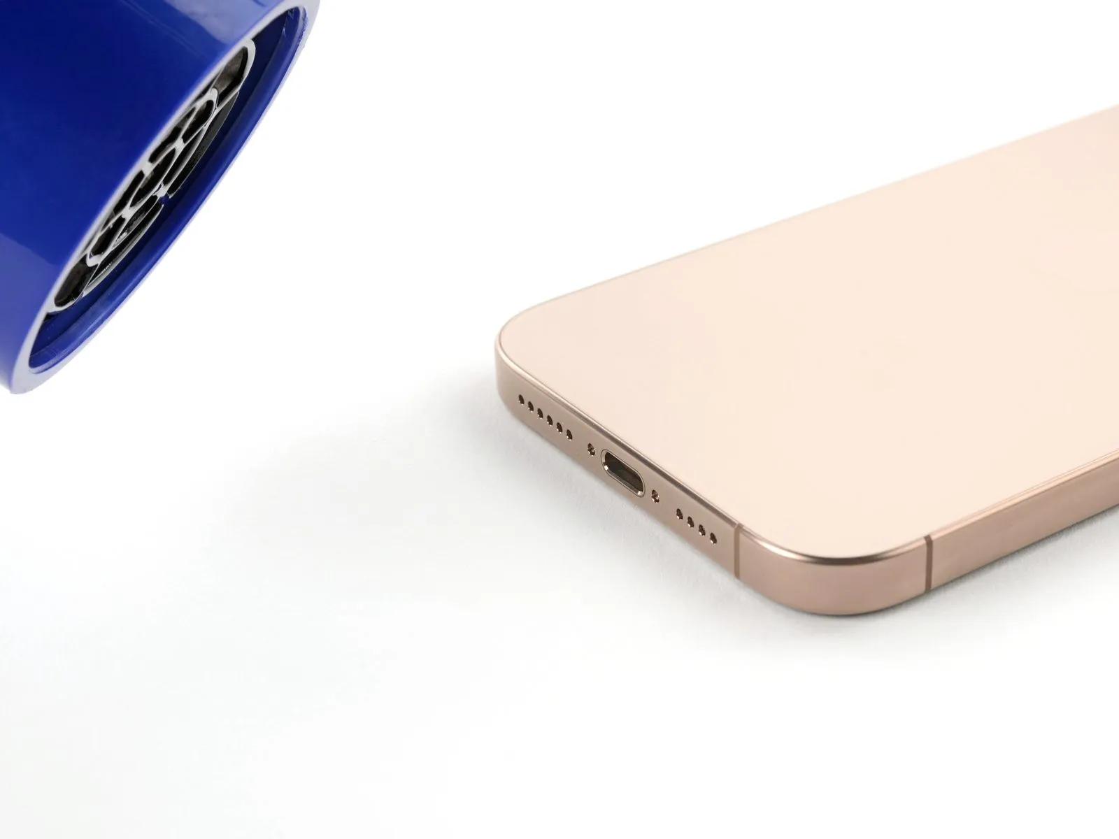
- Employing a hair dryer or heat gun, warm the lower perimeter of the rear glass panel until it reaches a temperature that is perceptible upon contact.
- Alternatively, an iOpener can be utilized for localized heating; adhere to the provided guidelines to ensure correct heating and application.
Step 6


- Secure a suction handle to the lower perimeter of the rear glass panel.
- Exert consistent, forceful upward pressure on the handle to establish separation between the glass and the device's frame.
- Should separation fail to occur, increase the localized heat application to the edge and attempt the process once more.
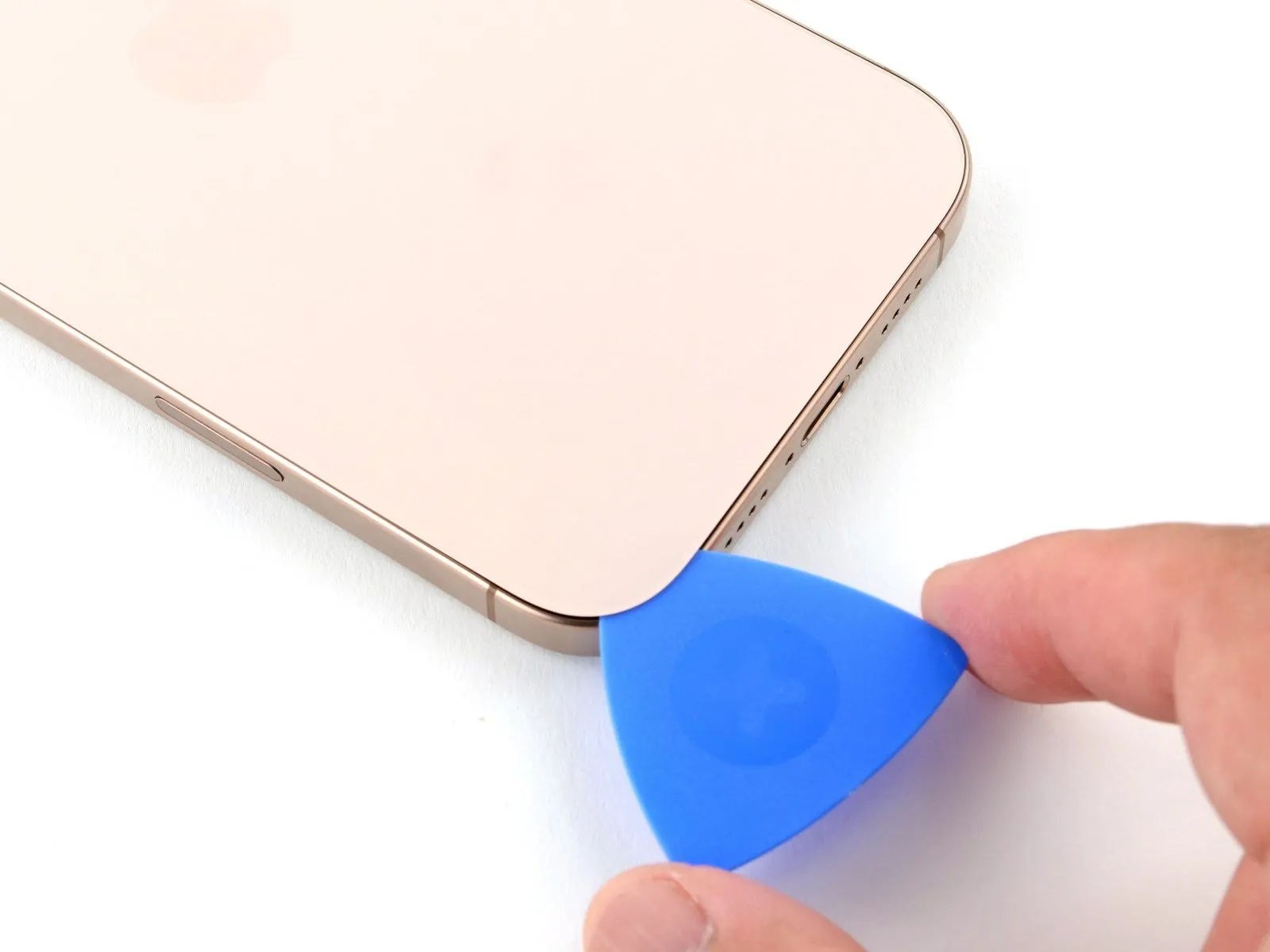
- Carefully introduce the pointed end of a separation tool into the newly formed space.
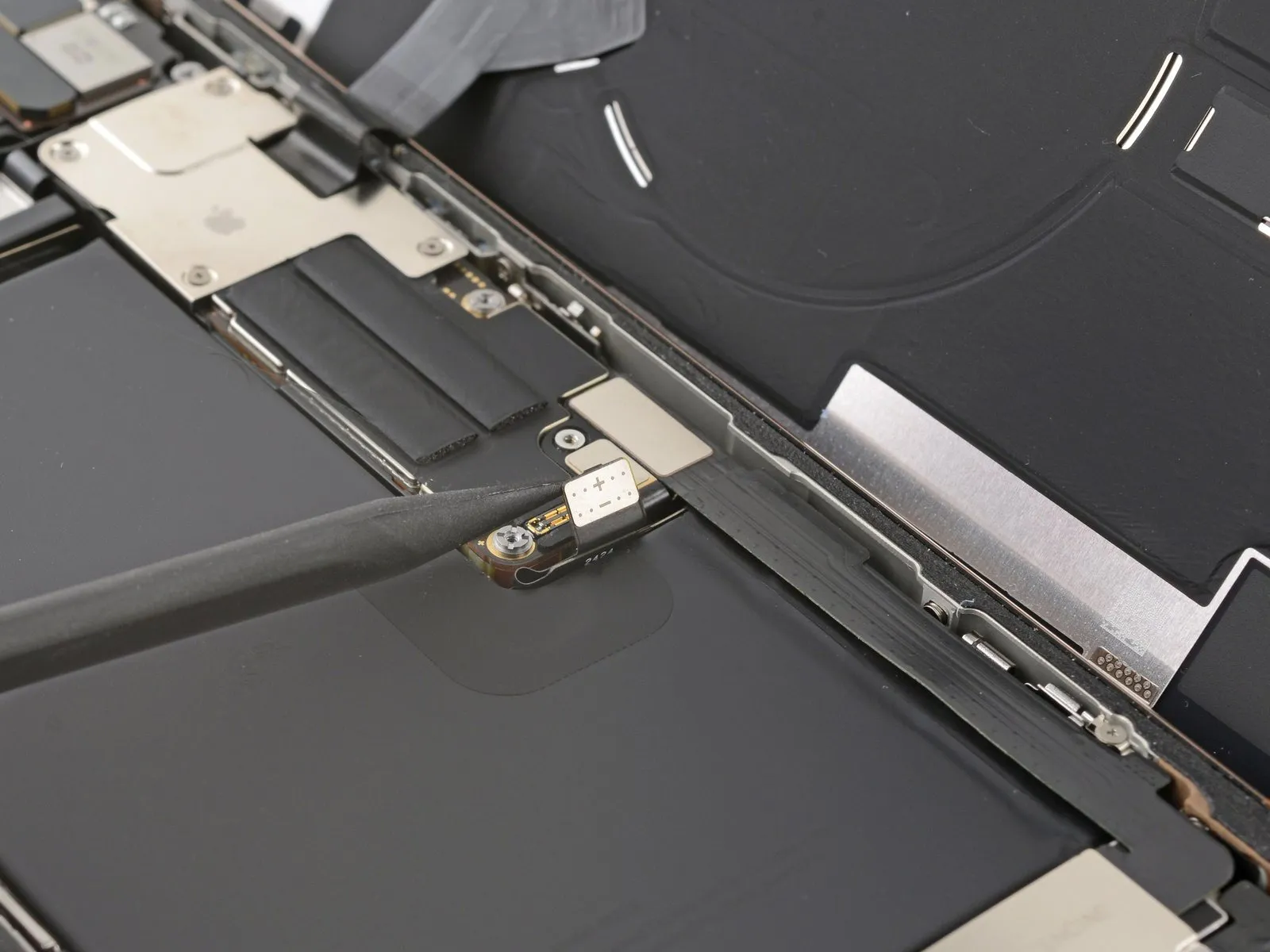
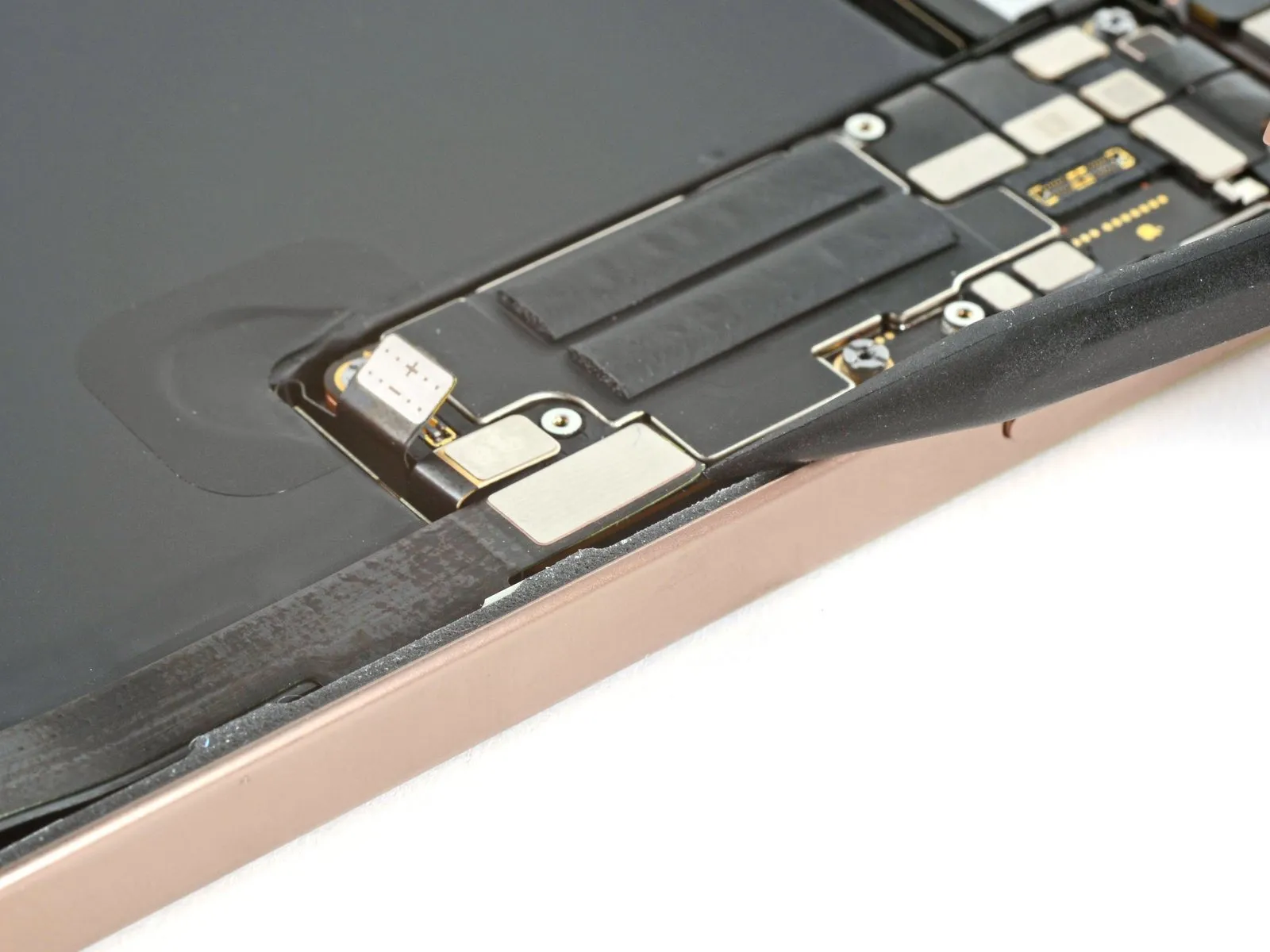
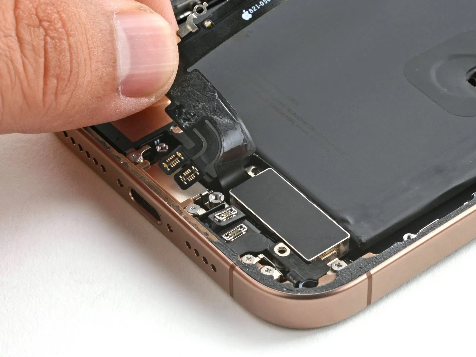
Step 7 | Back glass information
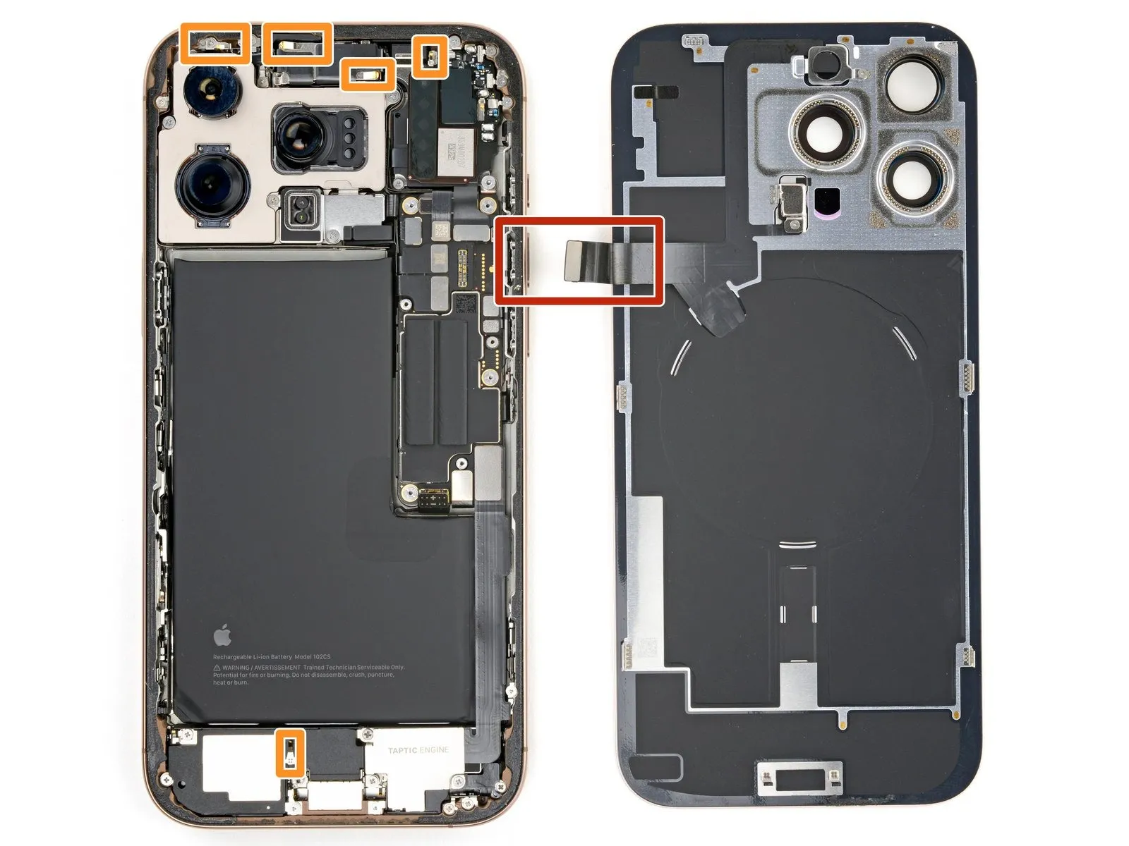
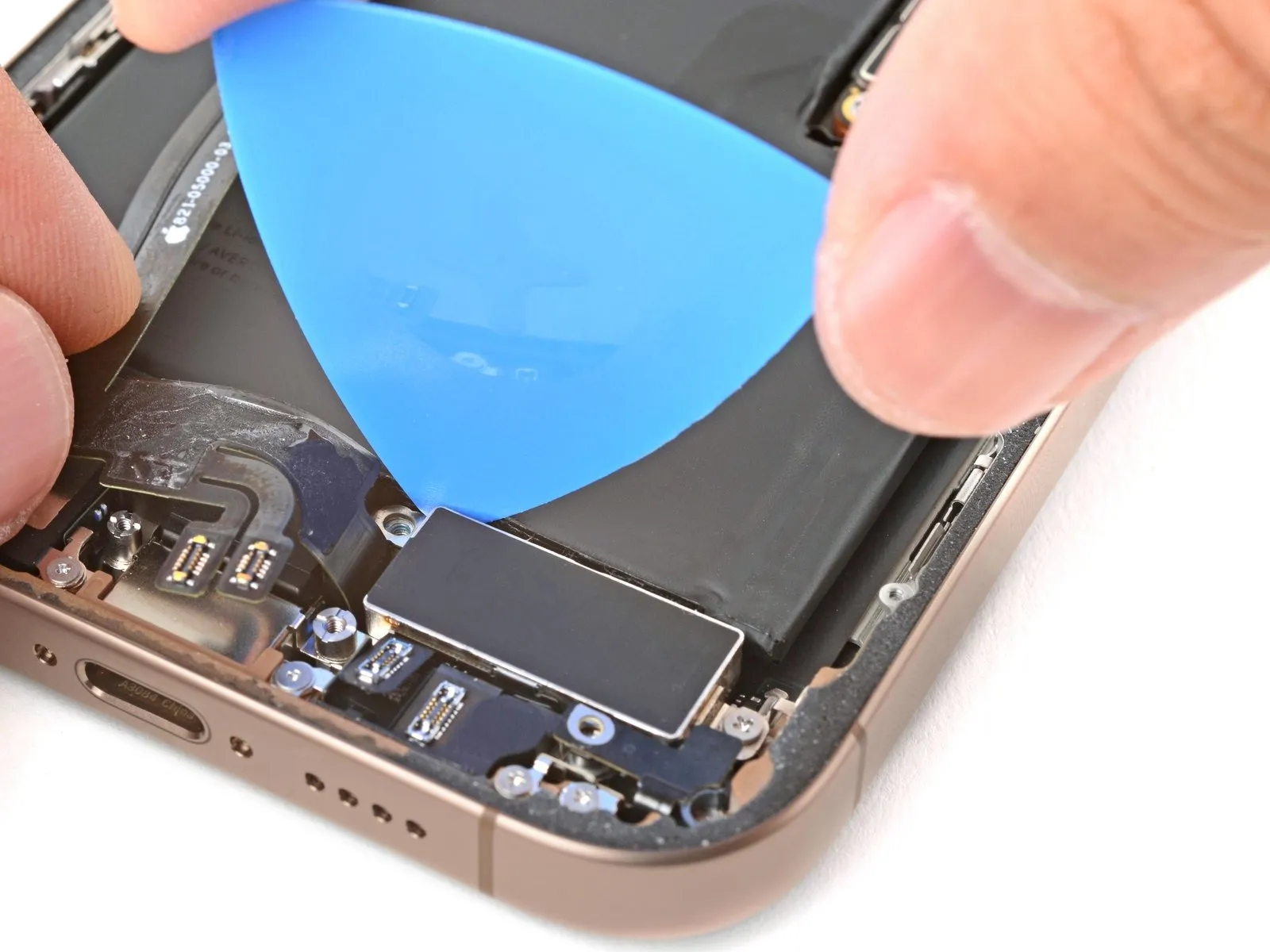
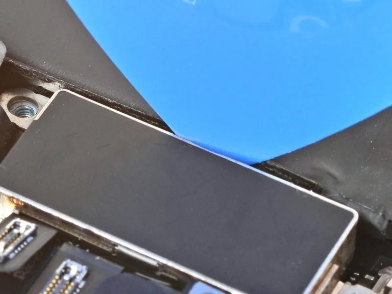
- During the process of separating the rear glass with a separating tool, maintain a maximum insertion depth of 3 millimeters to prevent potential harm to adjacent components.
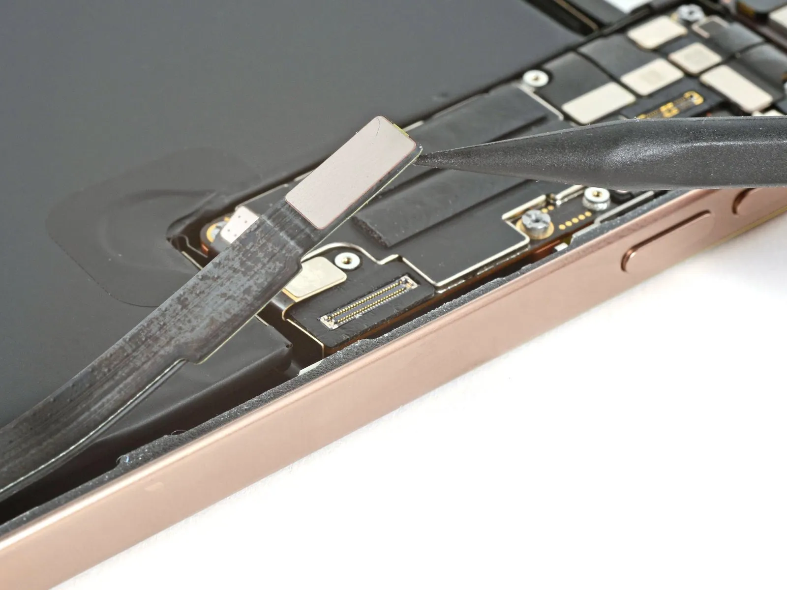
- A fragile connector, situated near the volume up button and linking the rear glass assembly to the iPhone's internal circuitry, requires careful avoidance during separation to prevent cable damage.
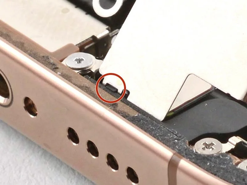
- Several spring-based electrical contacts are located along the iPhone's edges and should be protected from separation tool contact.
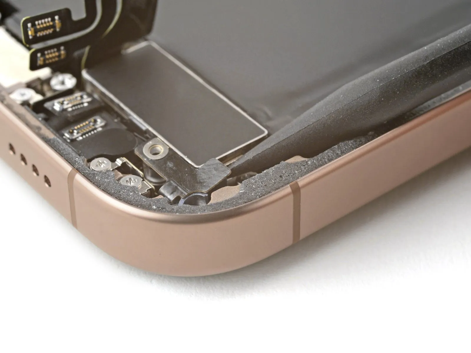
Step 8 | Separate the bottom edge adhesive

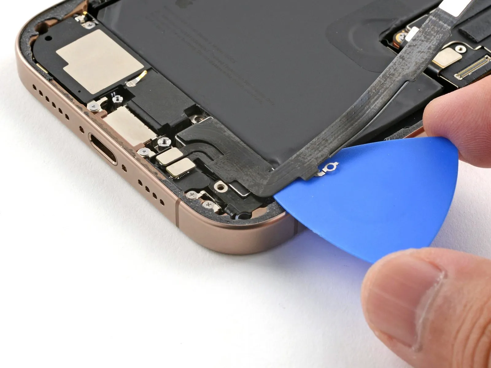
- Utilize the opening pick, moving it along the lower perimeter to sever the bonding agent.
- Should resistance be encountered while attempting to cut the adhesive, apply heat to the edge for approximately one minute, then retry the separation.
- Maintain the opening pick's position within the lower-left corner to inhibit the adhesive from reattaching.
Step 9 | Heat the left edge
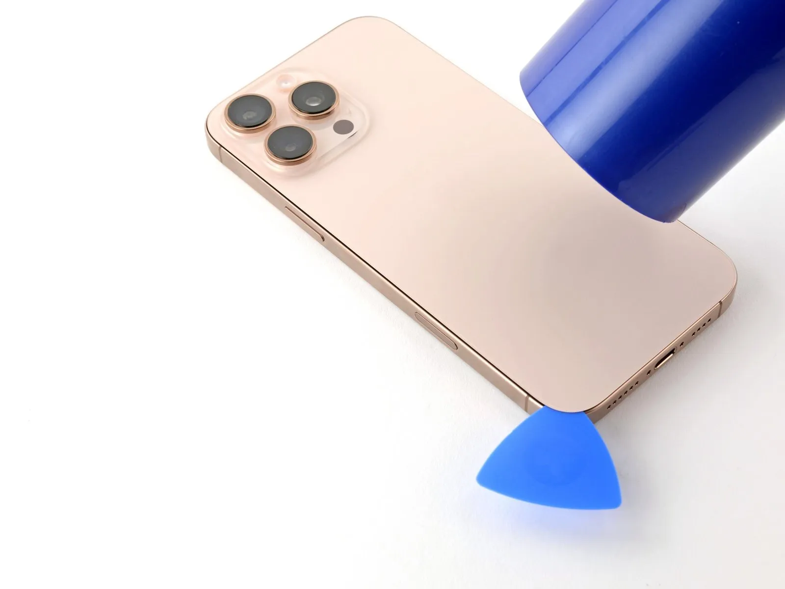
Applying warmth to the left perimeter of the rear glass panel with a hair dryer or heat gun is necessary.Elevate the temperature of the glass's left edge to a point where it registers as hot upon contact.This thermal application facilitates separation of the back glass.
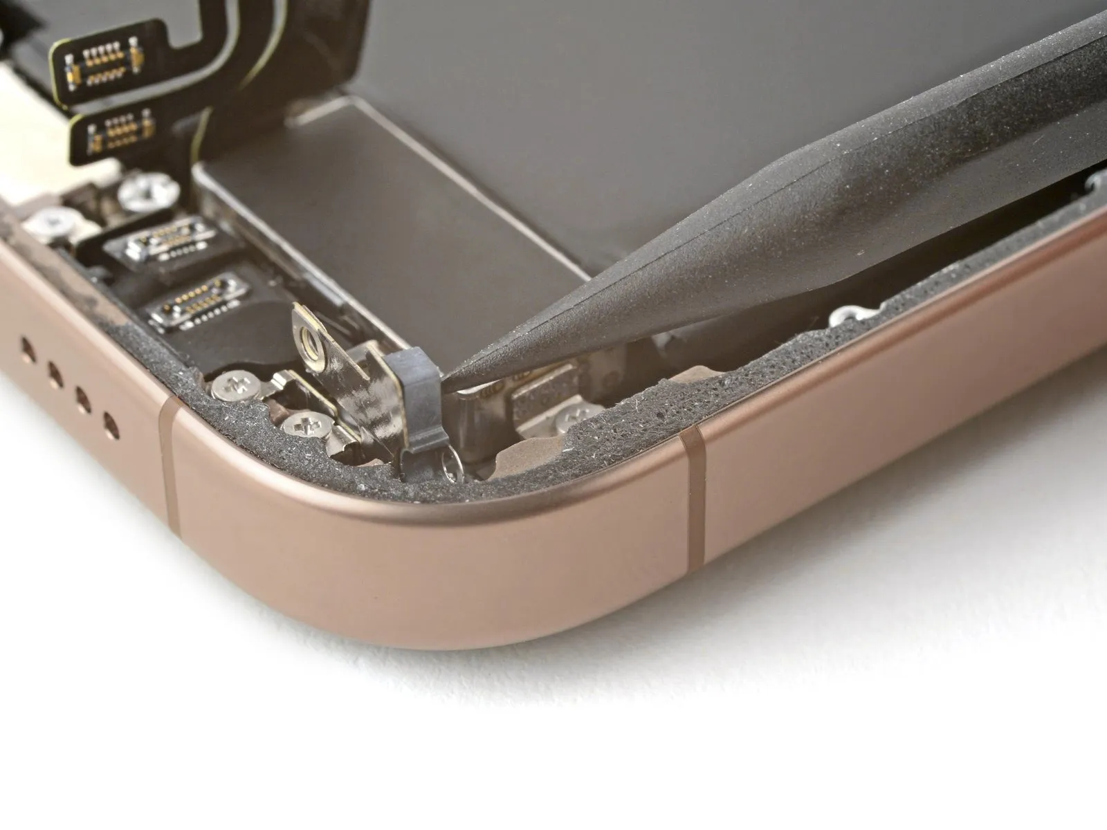
Step 10 | Separate the left adhesive

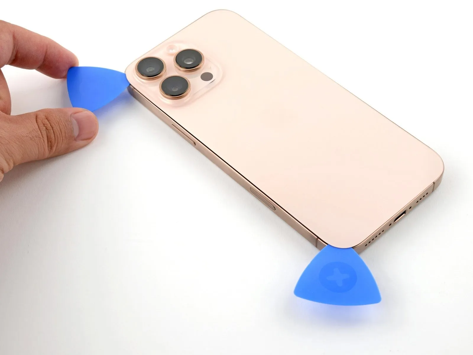
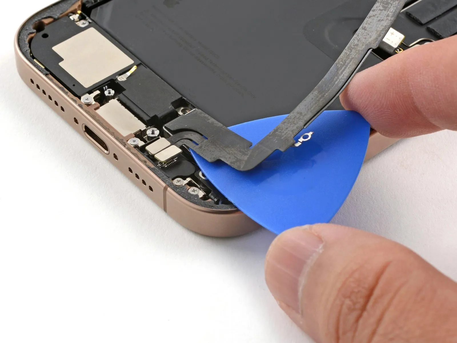
- Introduce a supplementary opening tool into the lower-left region, positioned near the already inserted tool.
- Ensure the tool's insertion depth remains below 3 mm to safeguard the spring contact points from harm.
- Move the tool along the left side to detach the adhesive and disengage the metal clips.
- Audible and tactile feedback will indicate the metal clips' release as the tool progresses.
- Maintain the initial tool's position within the upper-left corner to inhibit the adhesive from re-bonding.
Step 11 | Heat the top edge and corner

Apply warmth to the upper edge and upper-right corner of the rear glass panel utilizing a hair dryer or heat gun.Elevate the temperature of the specified areas until they reach a perceptible warmth.This heating process facilitates separation of the back glass from the device's frame.
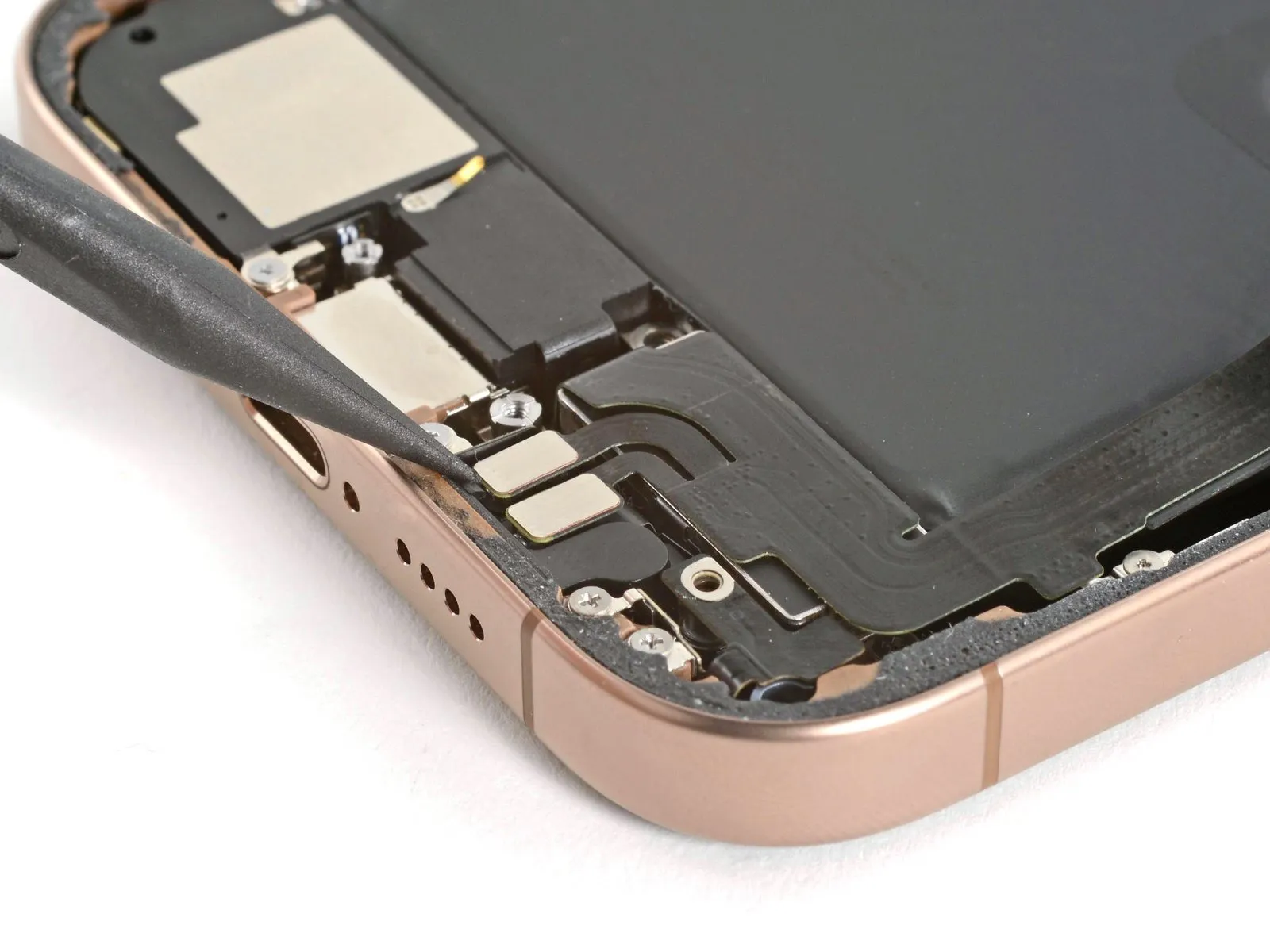
Step 12 | Separate the top adhesive

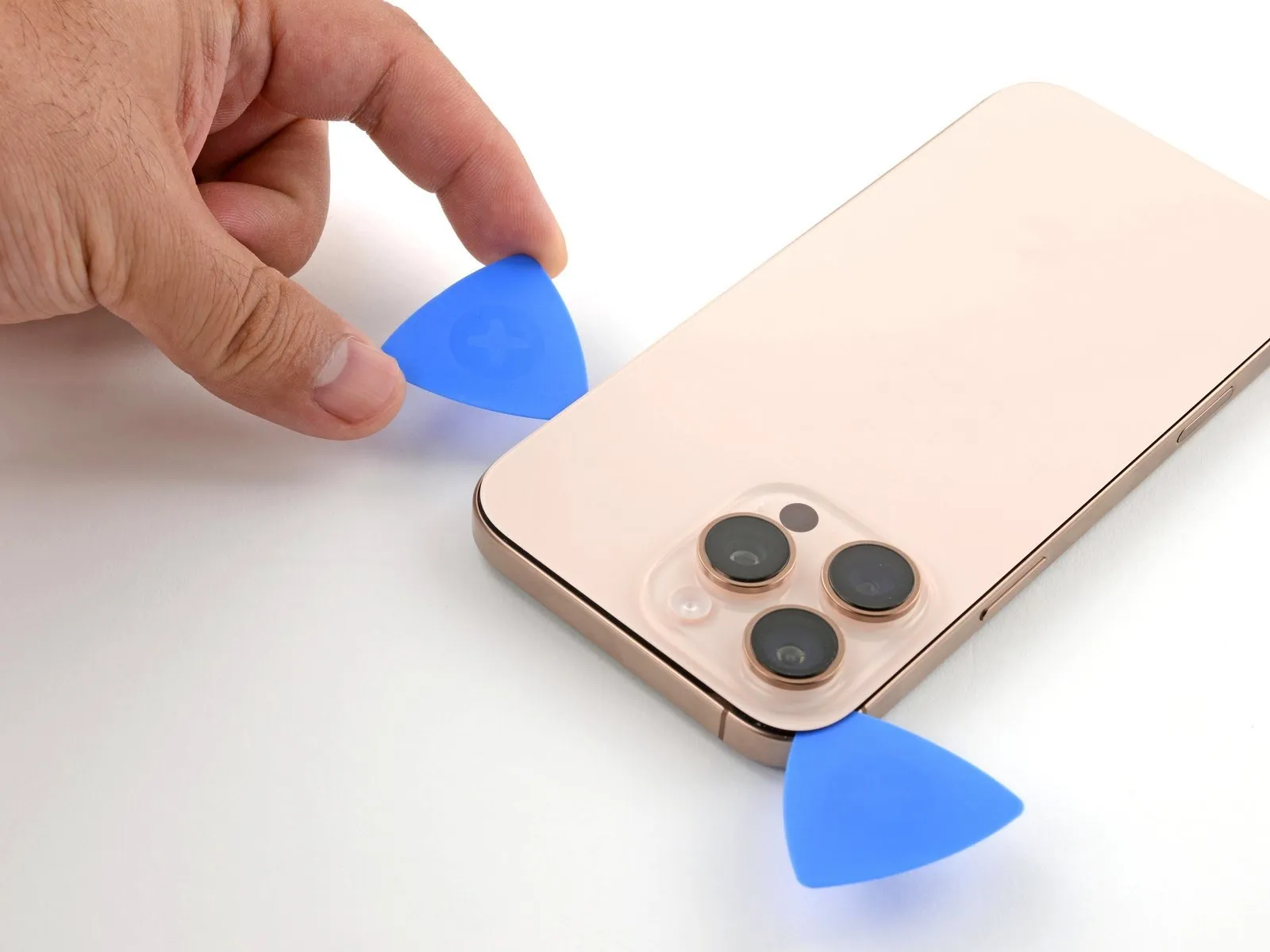
- To preclude harm to the spring contacts, ensure the insertion depth of your tool remains less than 3 millimeters.Employ a third specialized tool through the upper-left aperture.Advance this tool along the superior border, curving it around the upper-right corner, and pausing directly over the 'volume up' button.
- Maintain the placement of this tool to inhibit the adhesive from reforming a seal.
- Care must be taken to limit tool penetration to a maximum of 3 mm, safeguarding the delicate spring contact points.
- A third tool should be introduced via the top-left opening to facilitate the subsequent steps.
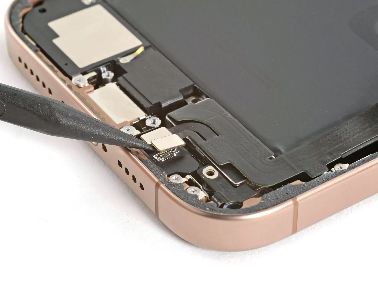
Step 13 | Heat the right edge

Step 14 | Separate the right adhesive


- Position a fourth opening tool within the lower-rightmost section of the device.
- Maneuver the opening tool along the corner's contour and upward along the right side, pausing its movement just beneath the volume down button.
Step 15 | Reposition the back glass

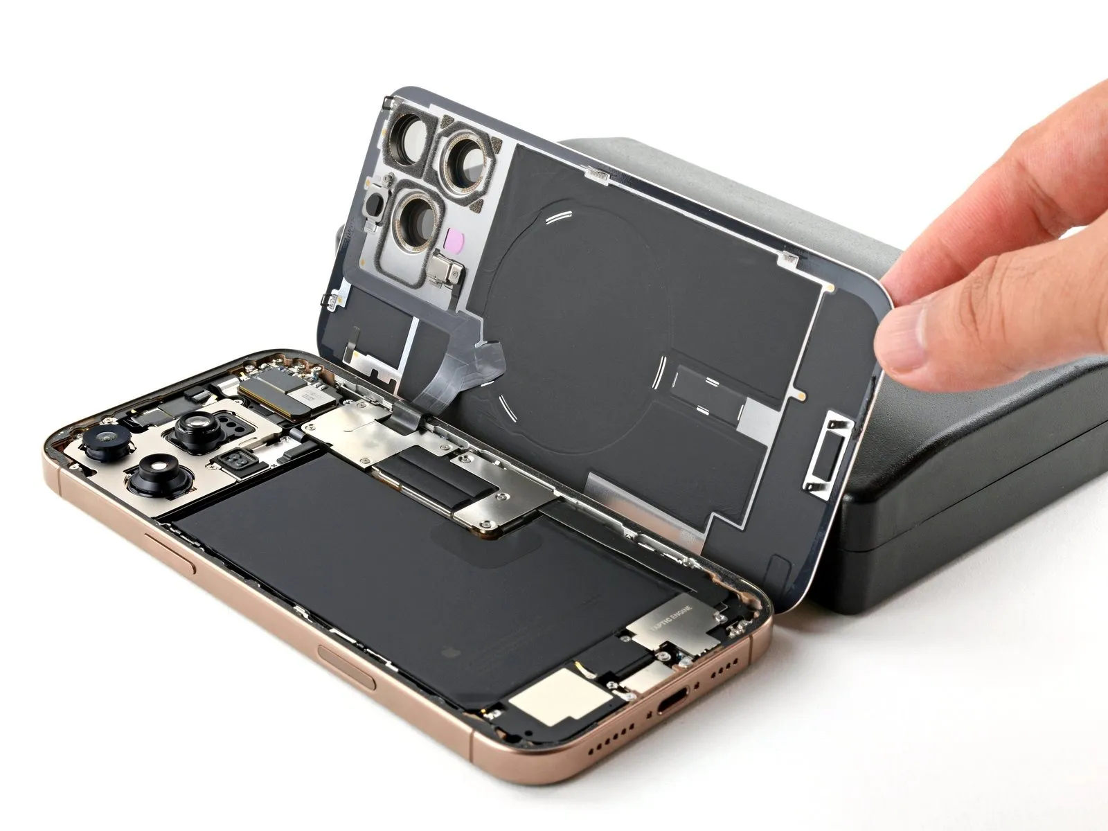
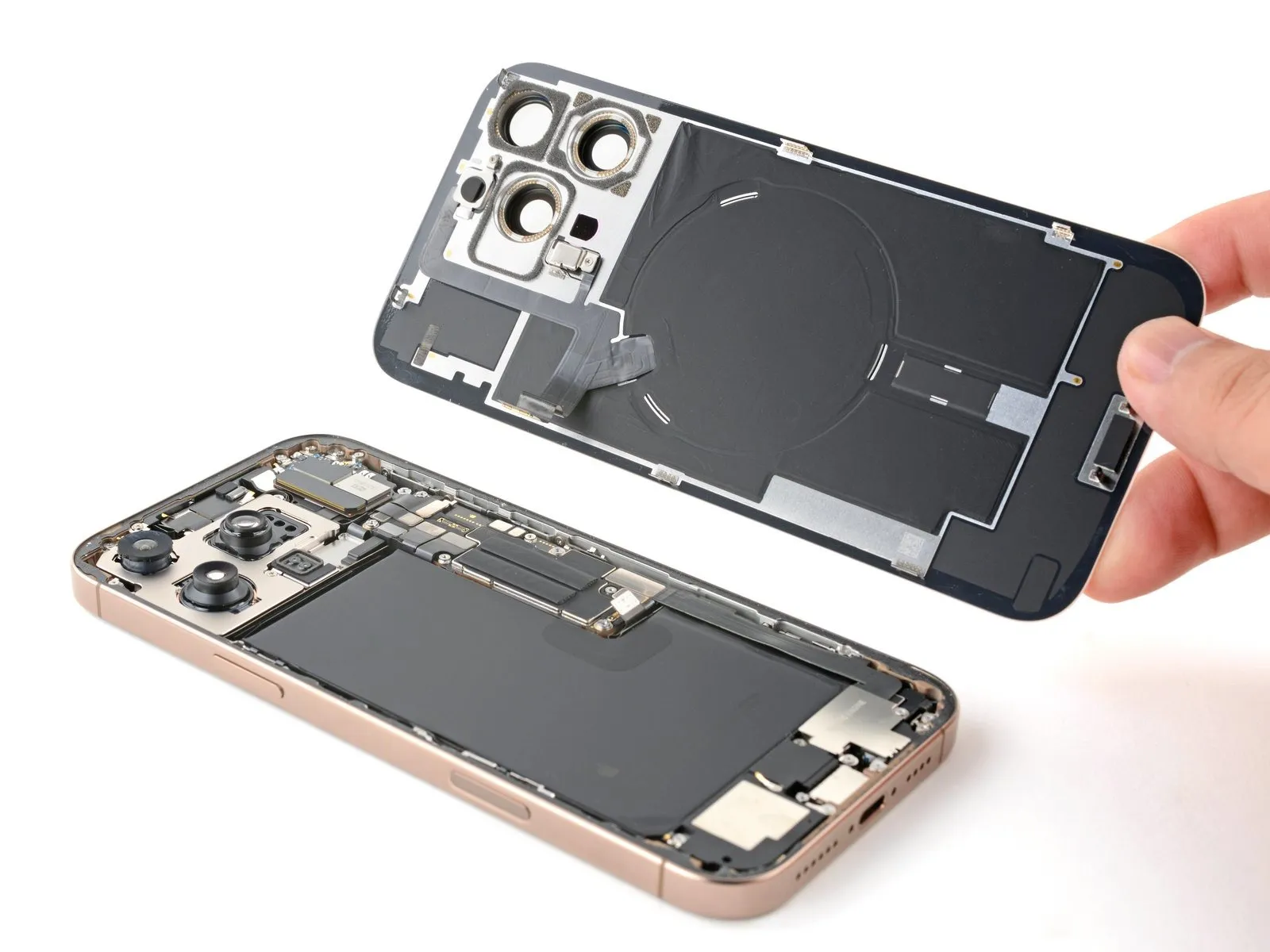
- Initiate the opening of the rear glass by pivoting it towards the right side of the iPhone, thereby breaking the remaining adhesive bond.
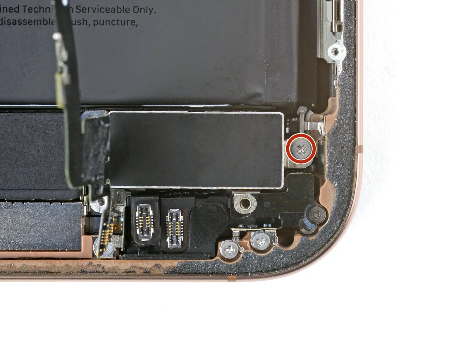
Step 16 | Remove the battery connector cover

- Three screws, each measuring 1.3 millimeters in length, are present.
- A single screw with a length of 1.0 millimeter is also used.
Step 17

Step 18 | Disconnect the battery
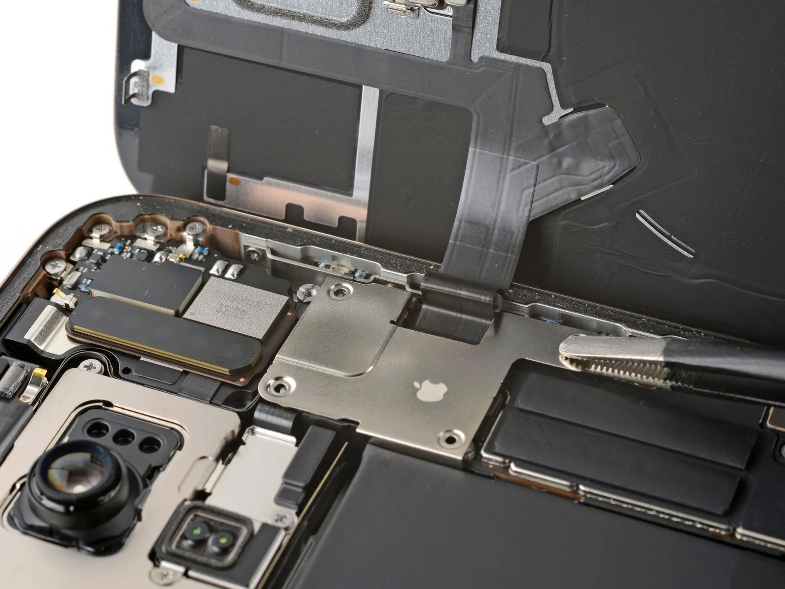
Step 19 | Remove the back glass connector cover

- The assembly includes two fasteners.These two fasteners are each 1.3 millimeters in length.Additionally, two other fasteners are present.
- These supplementary fasteners measure 1.0 millimeters in length.Carefully observe the screw lengths to ensure correct reassembly.Properly matching screw lengths is crucial for maintaining device integrity.
Step 20
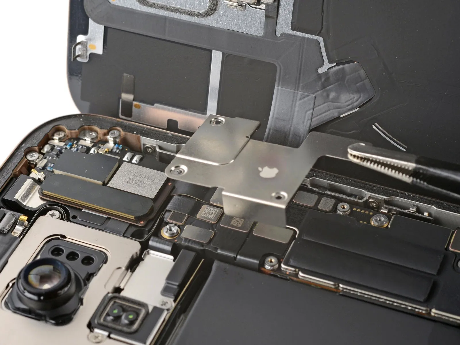
Step 21 | Remove the back glass
Step 22
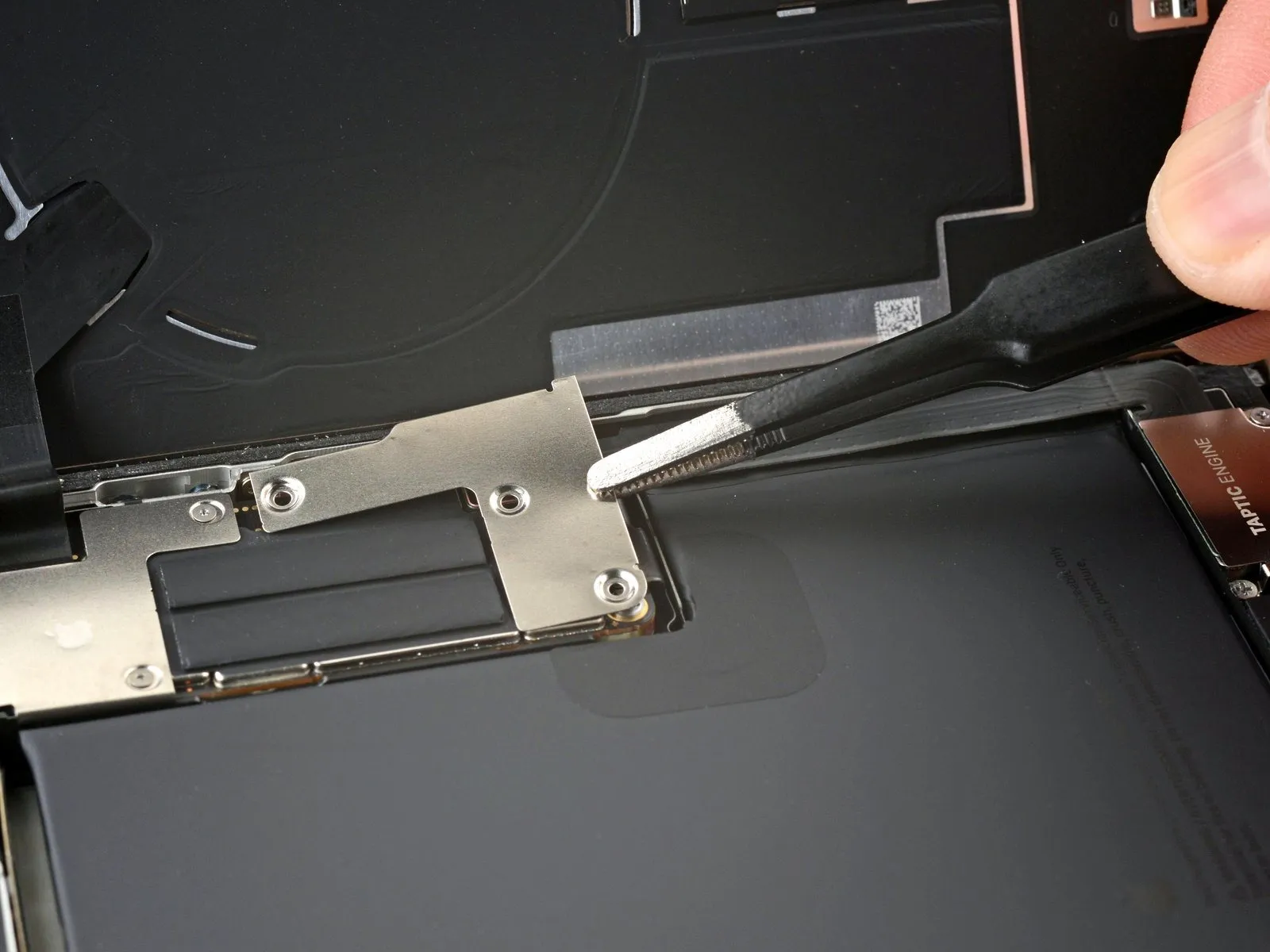
Step 23 | Remove the Taptic Engine cover
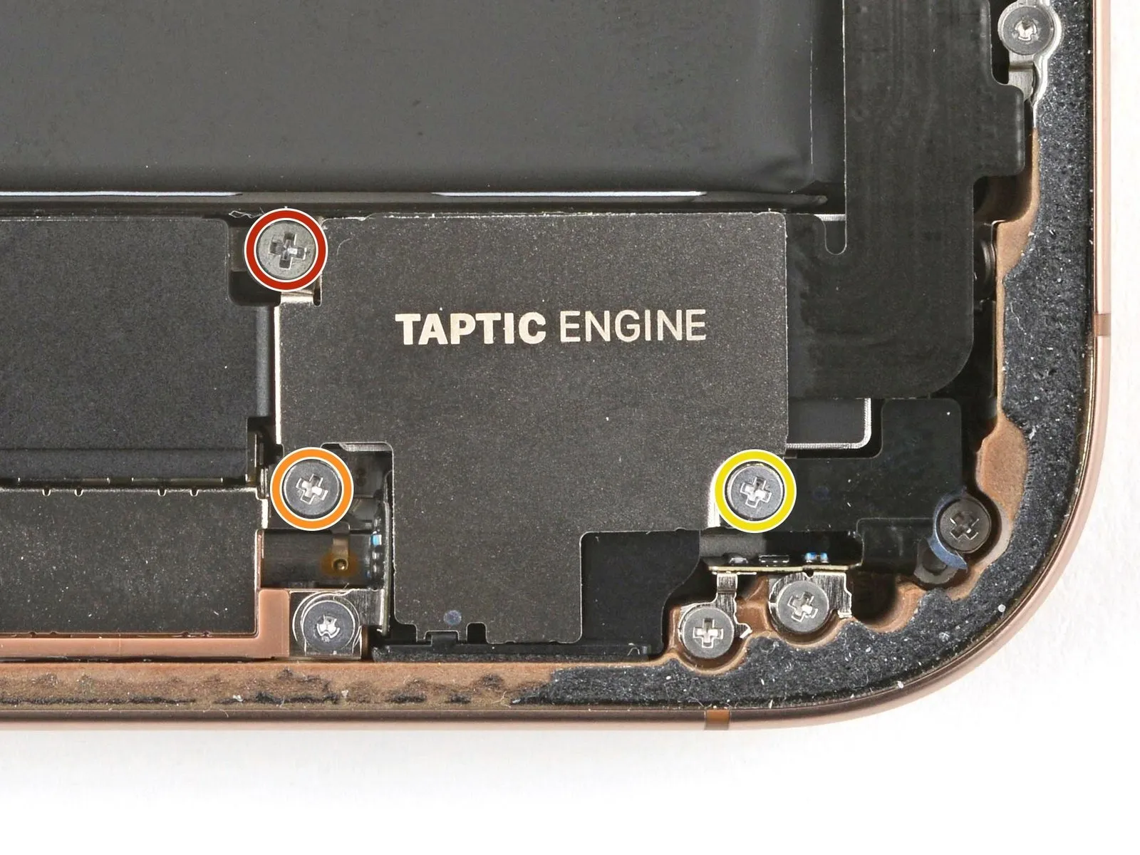

- Employ a Phillips screwdriver for the disassembly of the Taptic Engine cover, which is fastened by screws.A screw measuring 2.9 millimeters in length is among those securing the cover.Additionally, a screw with a length of 1.3 millimeters is used in the fastening process.
- The cover is also held in place by a screw that has a 2.4-millimeter length.
- The three screws holding the Taptic Engine cover in place must be removed using a Phillips screwdriver.
- The fasteners consist of one 2.9 mm screw, one 1.3 mm screw, and one 2.4 mm screw.
Step 24

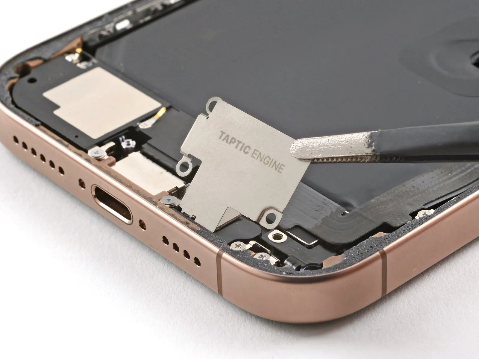

- Employ tweezers or manual dexterity to elevate the uppermost portion of the Taptic Engine cover.
- After the lower edge disengages from the device's frame, extract the Taptic Engine cover.
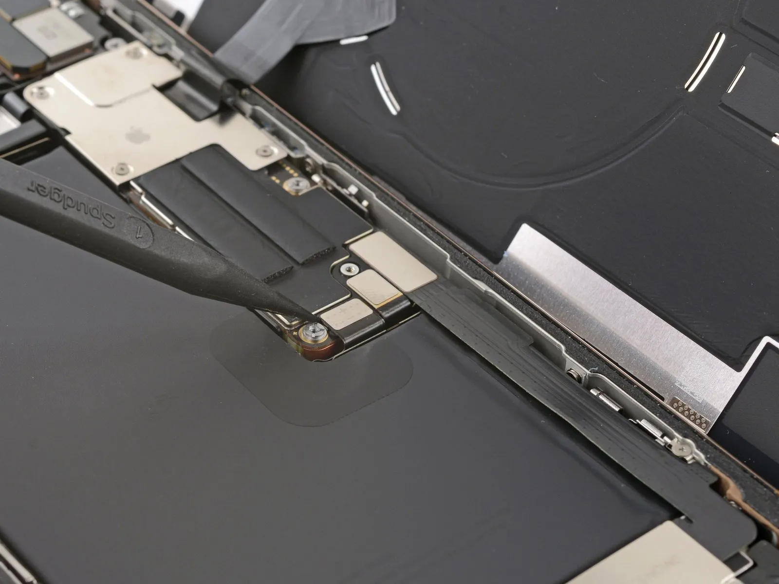
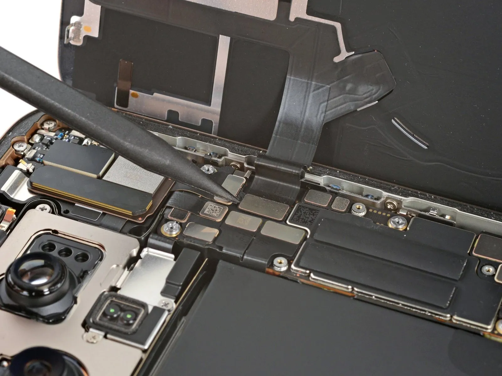
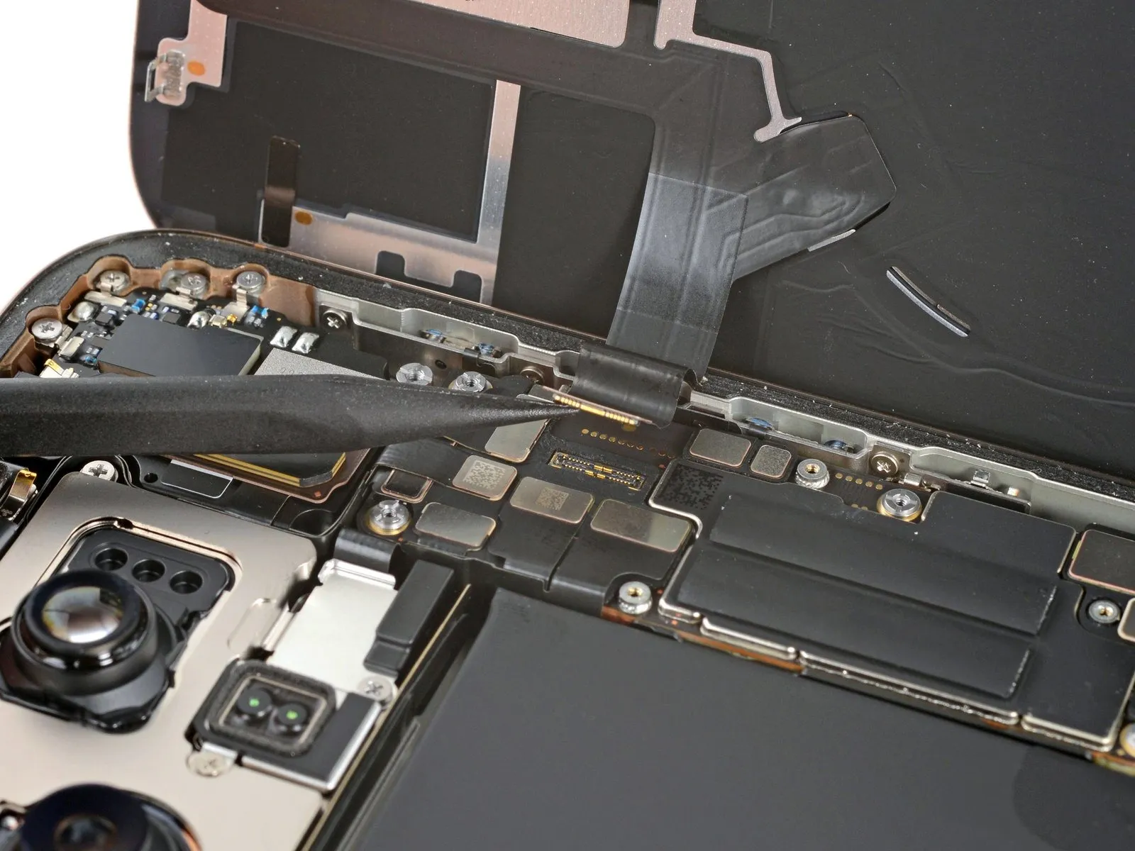
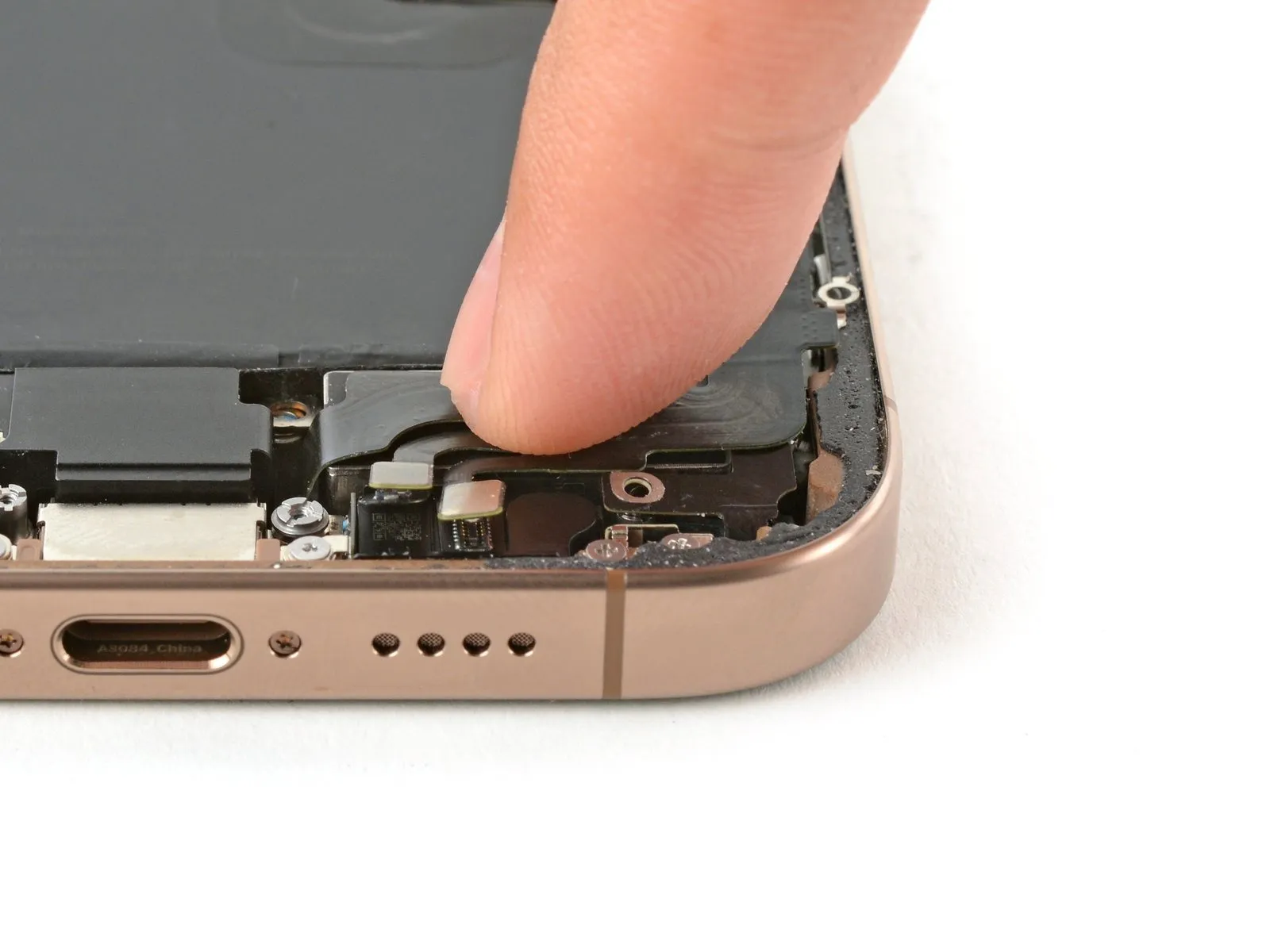
Step 25 | Loosen the lower assembly cable
- Employ the tip of a spudger to carefully lift and detach the lower assembly cable connector from the logic board’s corresponding interface.The spudger's pointed end facilitates separation of the lower assembly cable from its connection on the logic board.To release the lower assembly cable, utilize a spudger, applying force to its tip to disengage it from the logic board.
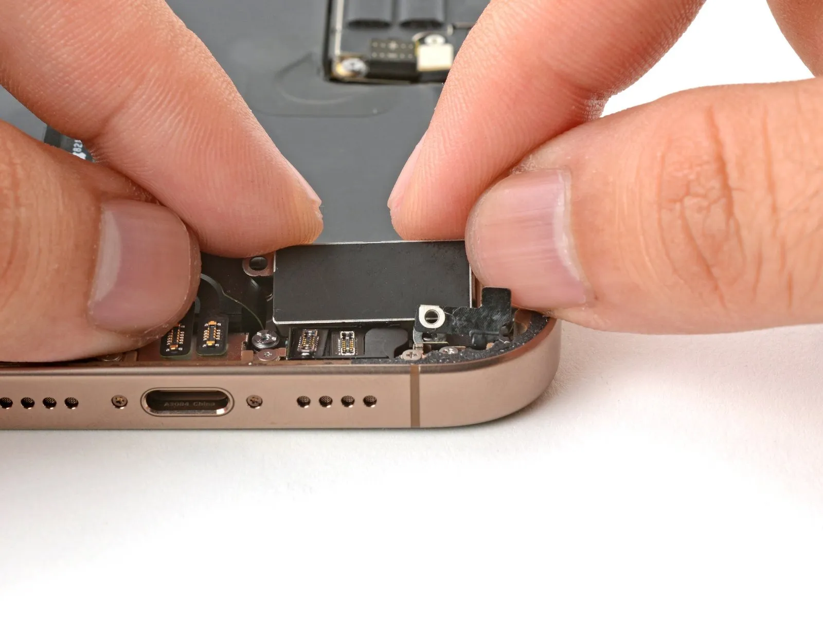
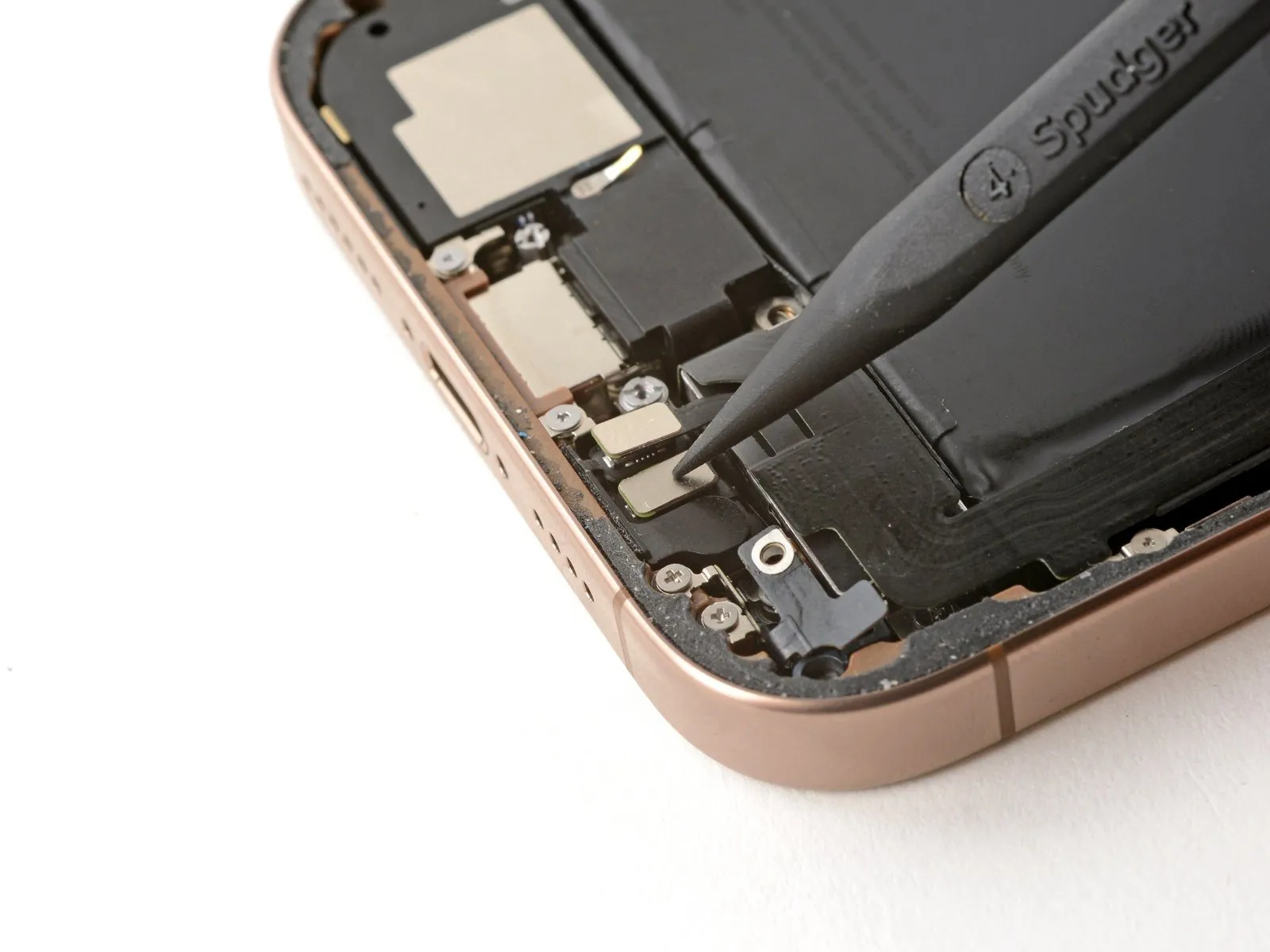
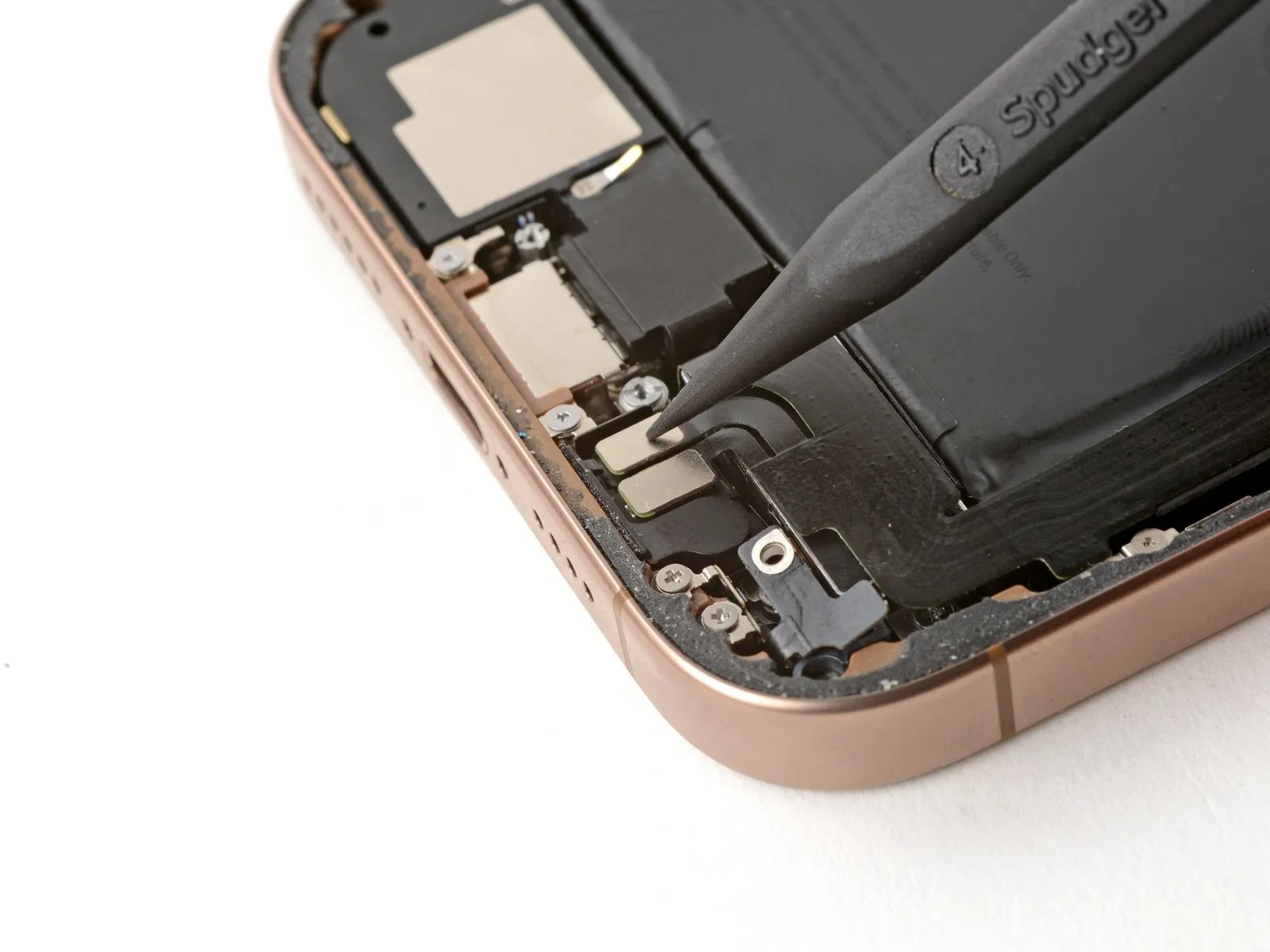
Step 26

- Employ the tip of a spudger to carefully lift and detach the pair of connectors situated close to the lower-right corner of the device's frame.The connectors, located on the bottom right edge, must be separated from their housings using the pointed end of a spudger.To release the two connectors positioned at the lower right of the frame, a spudger's pointed tip is required for prying and disconnection.
Step 27
- To detach the lower assembly cable, it is necessary to eliminate the two screws that hold it in place.
- A tri-point Y000 screw, measuring 1.0 millimeters in length, is required for this process.
- Additionally, a Phillips screw with a length of 1.3 millimeters will be needed.
Step 28

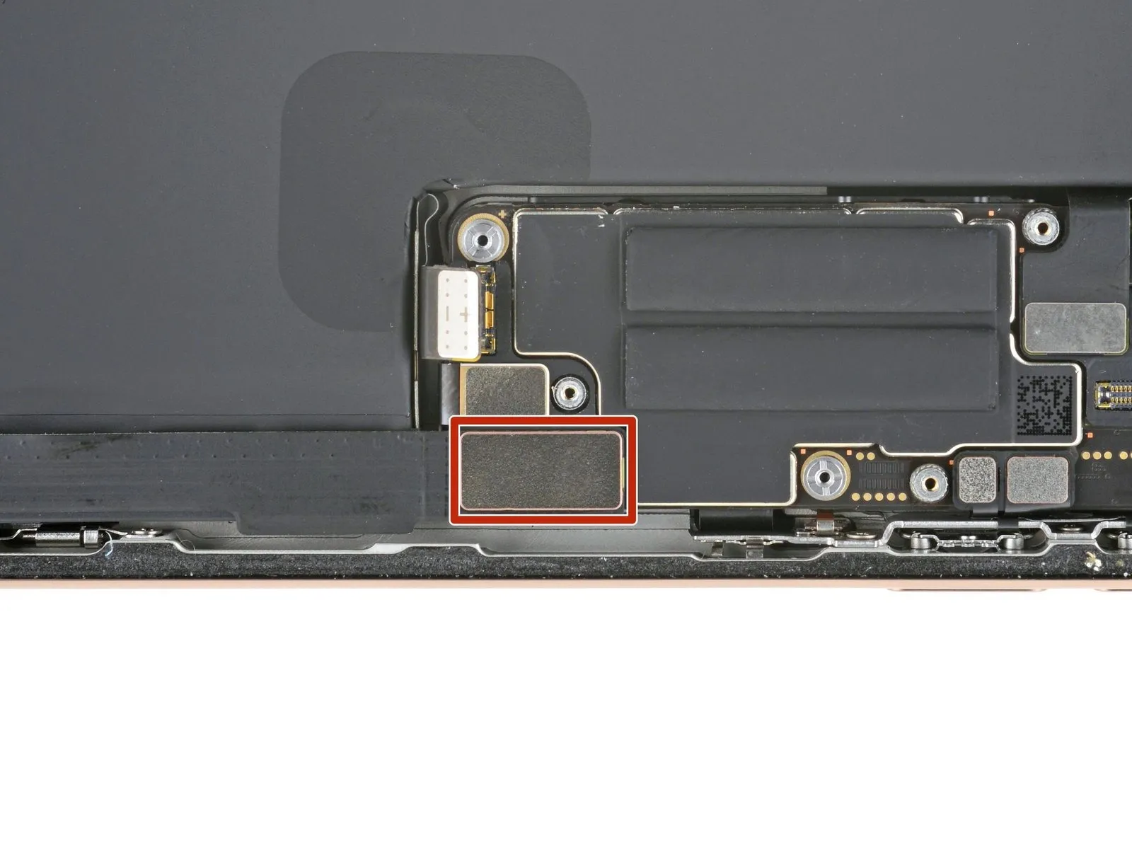
To loosen the adhesive securing the lower assembly cable to the Taptic Engine, apply heat to the cable's upper portion using a hair dryer until the surface becomes warm enough to comfortably touch.
Step 29
- Utilize an opening pick to insert beneath the lower assembly cable, facilitating its detachment from the Taptic Engine.To gain access to the Taptic Engine, gently maneuver the cable aside, ensuring it is not damaged.The separation of the lower assembly cable from the Taptic Engine is achieved by sliding the opening pick in.Positioning the opening pick allows for the disengagement of the cable from the Taptic Engine's connection.A careful bending motion of the cable is necessary to clear the path to the Taptic Engine.
- The Taptic Engine is located beneath the lower assembly cable, requiring careful manipulation to access.To avoid damage, the cable should be gently redirected, creating space for the Taptic Engine's removal.Accessing the Taptic Engine necessitates a deliberate and controlled movement of the lower assembly cable.
Step 30 | Remove the Taptic Engine
- Employ a Phillips screwdriver for the purpose of detaching the fastener.The screw, measuring 2.1 millimeters in length, requires a Phillips screwdriver for removal.A Phillips screwdriver is necessary to unscrew the component holding the Taptic Engine.To release the Taptic Engine, utilize a Phillips screwdriver to extract the screw.The Taptic Engine is affixed with a screw that necessitates a Phillips screwdriver for disassembly.A Phillips screwdriver is the appropriate tool for removing the 2.1 mm screw.For disassembly, a Phillips screwdriver is needed to remove the screw that secures the Taptic Engine.
Step 31
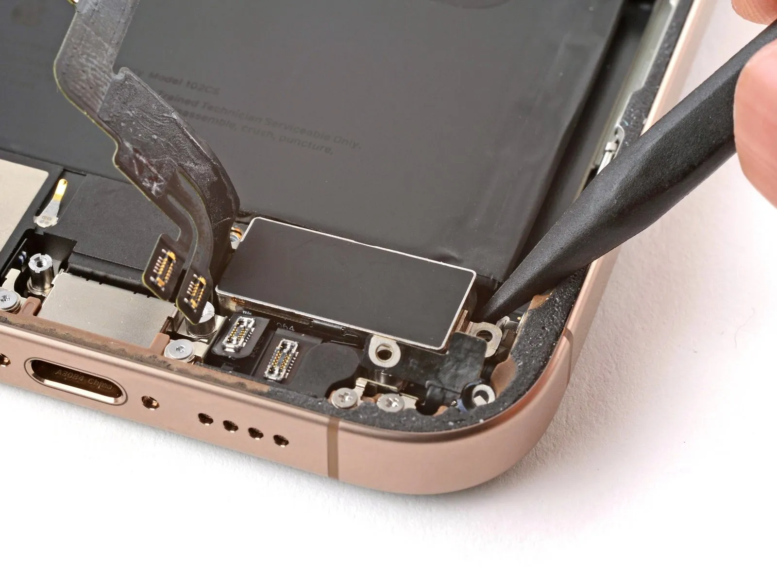
- Employ the tip of a spudger to gently lift the corner bracket.A spudger's pointed end facilitates prying the corner bracket upwards.To elevate the corner bracket, utilize the spudger's point as a fulcrum.
Step 32

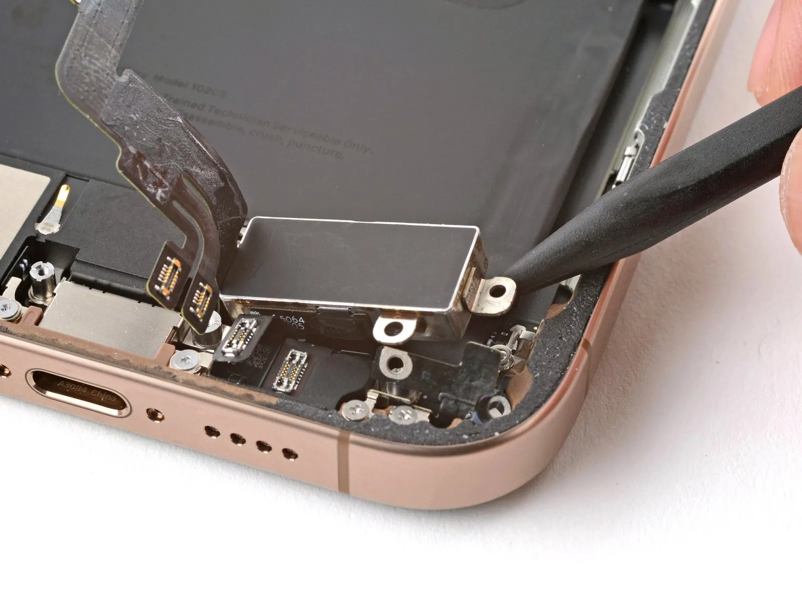
- Utilize the pointed end of an opening pick to gently disengage the Taptic Engine from its surrounding components.Position the opening pick's tip along the superior perimeter of the Taptic Engine.The plastic buffer strip, affixed to the Taptic Engine, requires separation via this method.A sliding motion with the opening pick facilitates detachment of the buffer strip.Carefully maneuver the pick to avoid damaging the Taptic Engine during the separation process.
Step 33
- Employ the tip of a spudger to gently lift the Taptic Engine.The Taptic Engine can be dislodged using a spudger's pointed end.Exercise caution to prevent the spudger from contacting the battery during this process.Avoid applying pressure to the battery while prying.Carefully detach the Taptic Engine from its position.
- The Taptic Engine must be removed with precision.
- Ensure the spudger is used to lever the Taptic Engine, not the battery.Complete the removal of the Taptic Engine.The Taptic Engine is now free from its mounting.
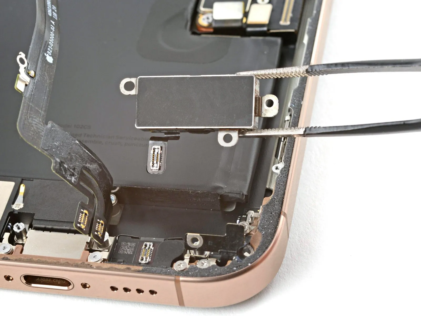
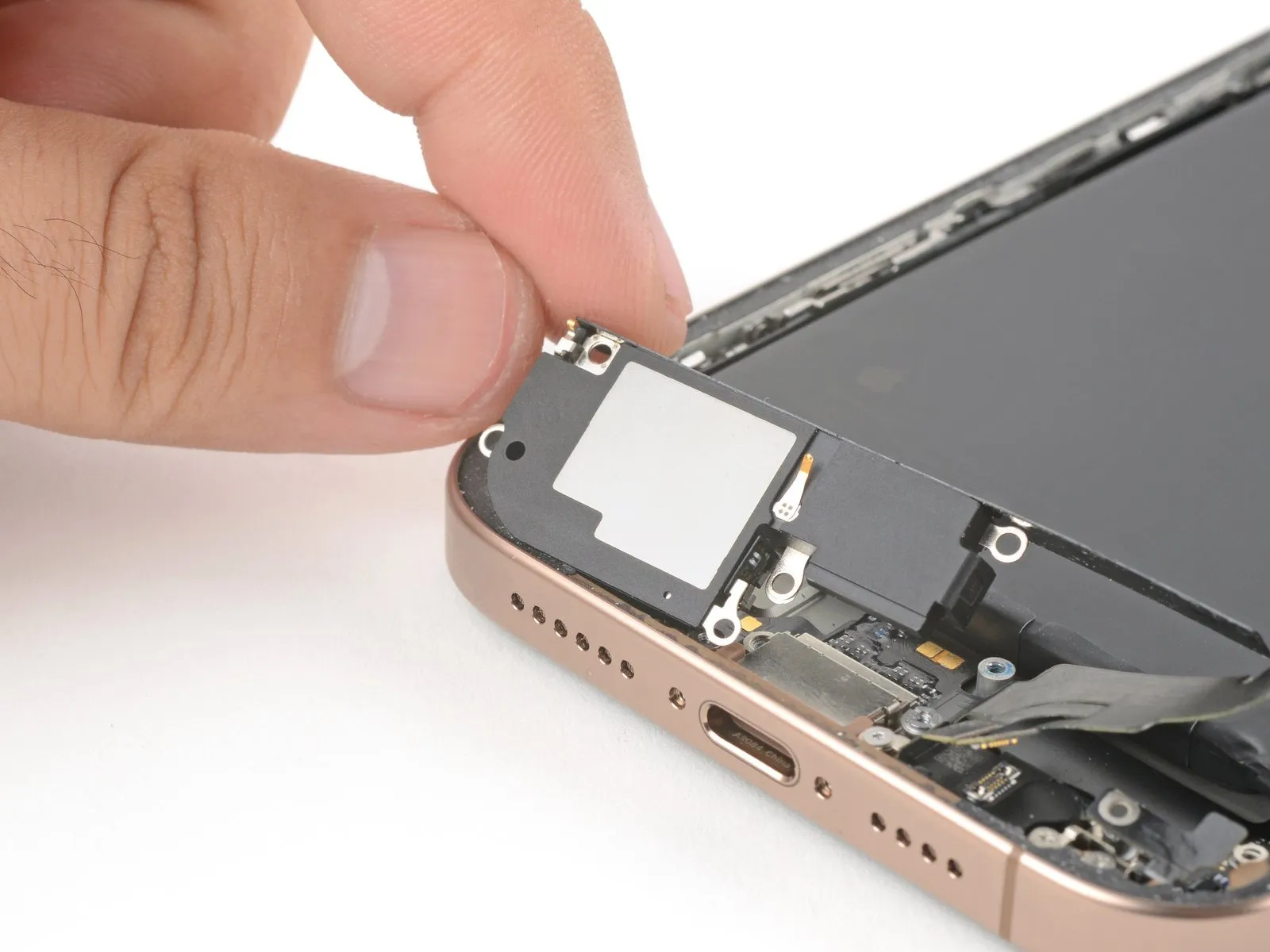
Step 34 | Remove the loudspeaker

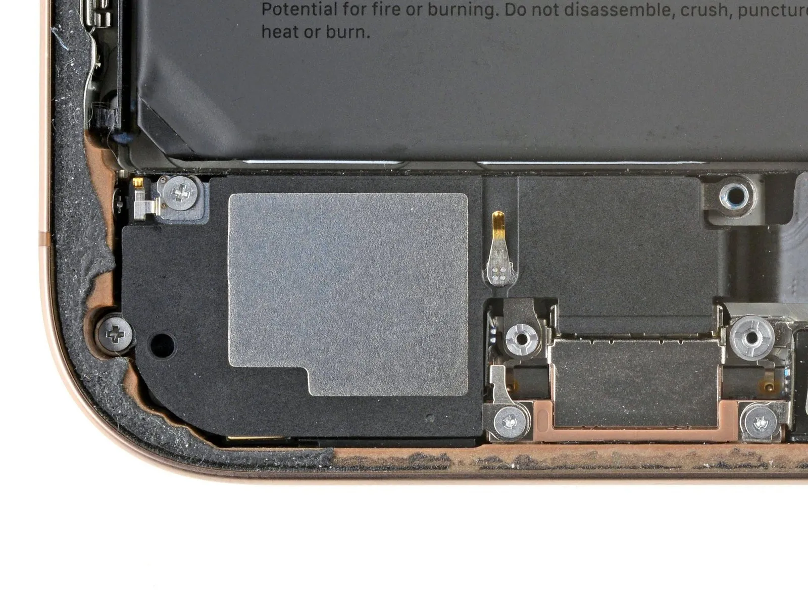
- To detach the loudspeaker, begin by eliminating the four screws that hold it in place.
- Utilize a Phillips screwdriver with a bit size of 1.The Phillips screw requires a length of 1.7 millimeters for proper engagement.
- Employ another Phillips screwdriver, also with a bit size of 1.This particular Phillips screw necessitates a length of 1.5 millimeters.
- Next, address a standoff screw, which requires a bit size of 1.The standoff screw's length is 4.1 millimeters.
- Subsequently, use a tri-point Y000 screwdriver to remove the final screw.This tri-point screw demands a length of 1.3 millimeters.
Step 35
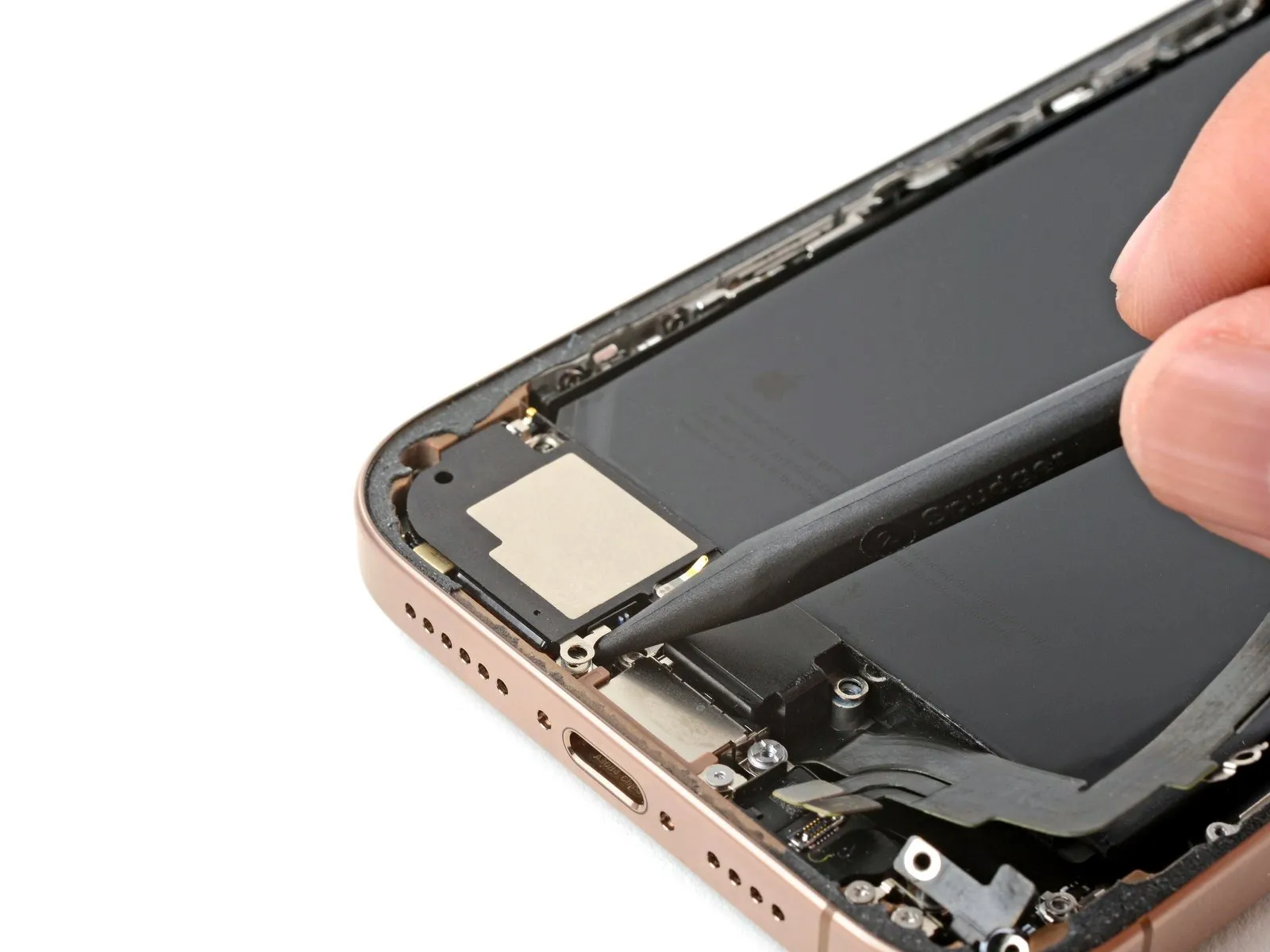
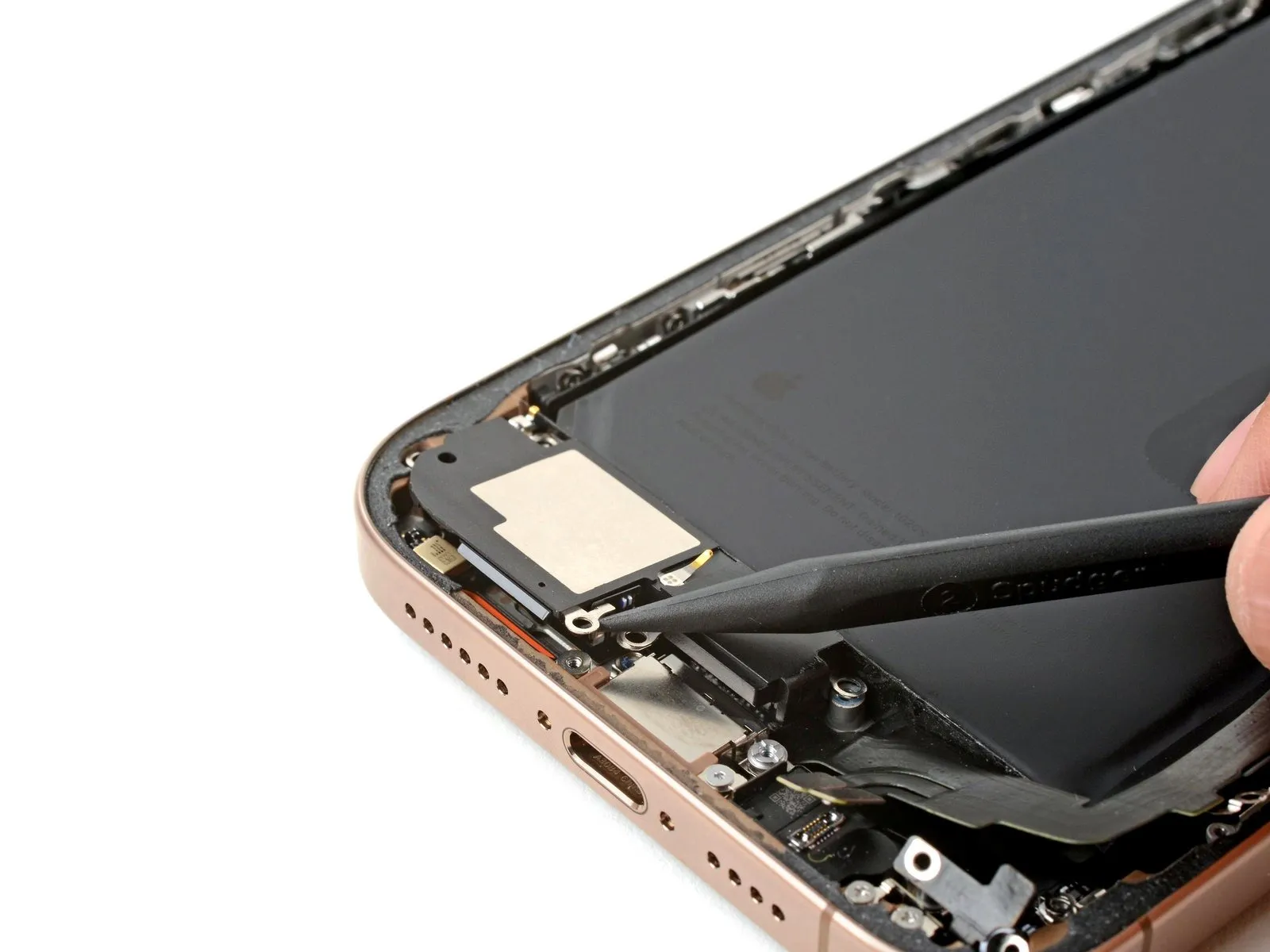
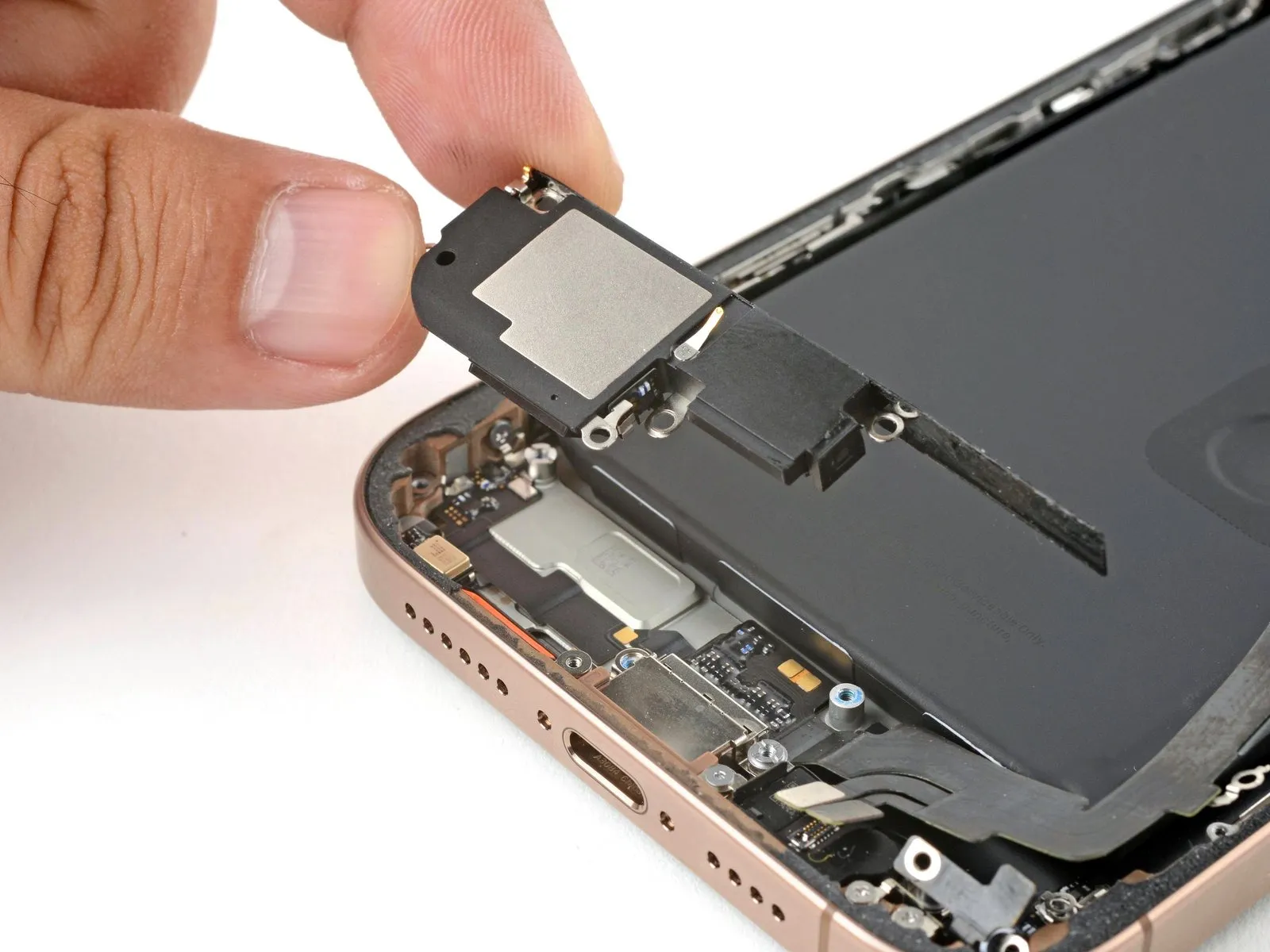
- Employing a spudger, carefully slide its tip into the opening located beneath the loudspeaker's securing screw on the right side.Applying gentle upward force with the spudger, disengage the loudspeaker from its mounting.The loudspeaker assembly should now be free and able to be removed.
- Complete the removal process by lifting the loudspeaker directly away from the device.
Step 36 | Disassembly complete

Having finished the disassembly process, the subsequent instructions detail the reassembly procedure for your iPhone.
Slight variations in the visual appearance of reassembly images might occur based on the specific iPhone model being serviced; however, the outlined steps remain accurate for all supported devices.
Step 37 | Install the loudspeaker
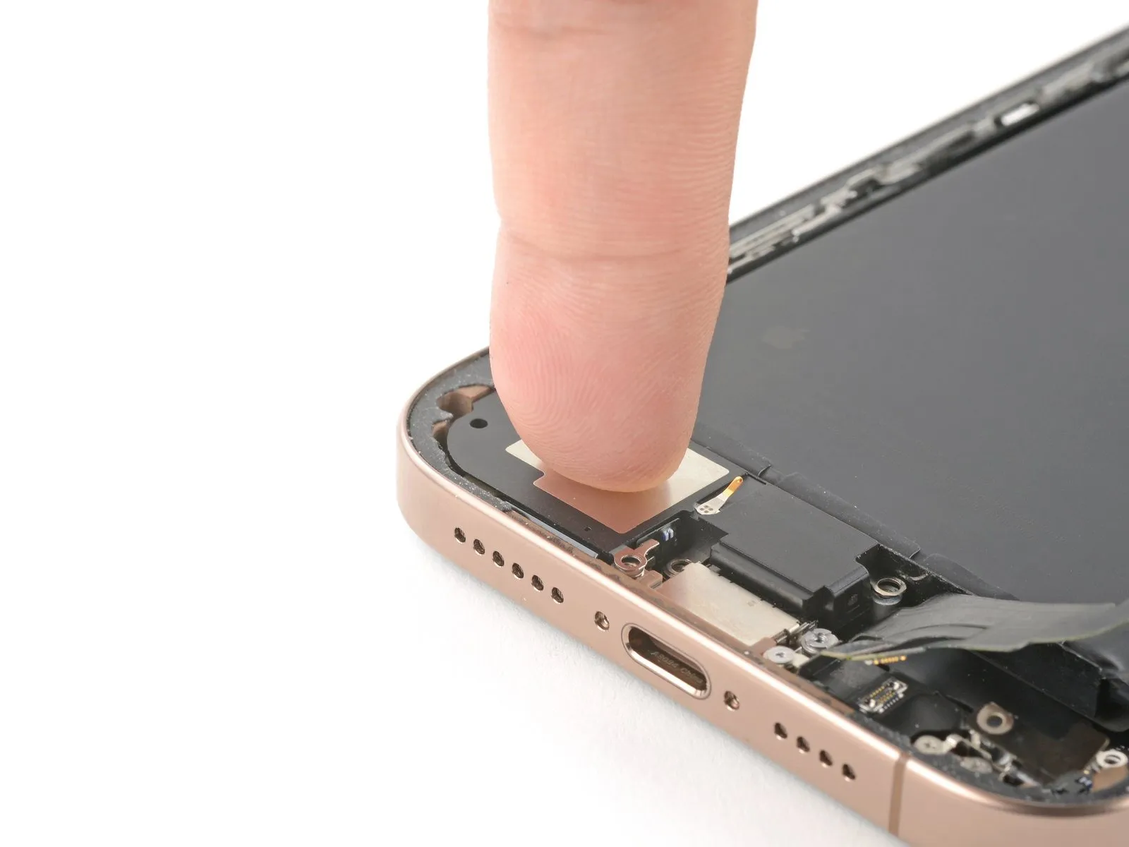
- Orient the lower extremity of the loudspeaker so that it aligns with the frame's contours.
- Secure the loudspeaker within its designated cavity by applying firm, even pressure.
Step 38
- To affix the loudspeaker, utilize four screws designed for this purpose.
Employ a Phillips screw with a length of 1.7 millimeters for the installation.
A Phillips screw, measuring 1.5 millimeters in length, is also required.
Secure a standoff screw, specifically 4.1 millimeters in length, during the process.
A tri-point Y000 screw, with a length of 1.3 millimeters, completes the necessary hardware.
Step 39 | Install the Taptic Engine
Position the Taptic Engine within its designated cavity.
Step 40

Position the corner bracket by leveraging a finger to rotate it downwards into its designated location.
Step 41
Employ a Phillips screwdriver for the installation process.A 2.1-millimeter-length screw is required for this step.The screw's purpose is to fasten the Taptic Engine.Ensure proper alignment before tightening the screw.The Phillips screwdriver is the appropriate tool for this fastener.Carefully position the screw to avoid damaging surrounding components.Securely affix the Taptic Engine with the provided screw.
Step 42
Apply slight pressure to secure the lower assembly cable to the Taptic Engine's surface using manual finger placement.The Taptic Engine is the component requiring cable connection.Ensure proper alignment and contact between the lower assembly cable and the Taptic Engine during the connection process.
Step 43
- To affix the lower assembly cable, utilize two screws for secure attachment.
- A single fastener required is a tri-point Y000 screw, measuring 1.0 millimeters in length.Additionally, a Phillips screw, extending 1.3 millimeters, is also necessary for this step.
- Ensure proper alignment before tightening the screws to prevent damage.The specified screws provide the necessary holding force for the cable's connection.
Step 44
Employing either a fingertip or a spudger tool, establish a secure connection between the two lower assembly cable connectors by applying pressure.The connectors must be firmly joined to ensure proper electrical contact.A spudger can be utilized as an alternative to manual finger pressure for achieving this connection.
Step 45
Position the Taptic Engine cover over the device, carefully matching the screw openings.Precise alignment of the cover is essential for subsequent screw installation.Verify secure engagement of the cover's lower perimeter with the device's frame.
Proper latching of the bottom edge guarantees a complete and stable enclosure.
Step 46
Employ a Phillips screwdriver to fasten the three screws that hold the Taptic Engine cover in place.A 2.9-millimeter-long screw is required for one of the securing points.A 1.3-millimeter-long screw is needed for a different attachment location.A 2.4-millimeter-long screw is used for the final fastening point.The Taptic Engine cover is affixed with a combination of screw lengths.
- Secure the cover using the specified screw lengths to ensure proper attachment.Properly aligning the screws is necessary for a secure fit of the Taptic Engine cover.
- Ensure the Phillips screwdriver is appropriately sized to avoid damaging the screw heads.The three screws are essential for maintaining the integrity of the Taptic Engine cover's attachment.
- Carefully install each screw, observing the designated length for each position.Refer to the parts list to confirm the correct screw lengths before installation.
Step 47
Secure the assembly cable connector to the logic board by applying pressure with either a fingertip or a specialized plastic pry tool.
Step 48 | Remove the leftover adhesive


Exercise caution near the delicate grounding clips during frame cleaning; accidental displacement can be corrected by carefully repositioning them with your fingers or tweezers.
- Employ blunt nose tweezers or manual manipulation to detach sizable adhesive portions from the frame's edges.
- Employ a spudger to eliminate remaining adhesive traces adhering to the frame's surface.
- Should the adhesive prove difficult to remove, utilize a hair dryer or heat gun to apply warmth, then attempt removal once more.
Step 49 | Clean the back glass


Step 50 | Clean the frame

- To prevent scratching, cover the spudger's tip with a clean, lint-free cloth or a coffee filter, then dispense a small amount of isopropyl alcohol with a concentration exceeding 90 percent onto the covering.Employing a single direction, carefully remove adhesive remnants from the frame's edge by wiping with the dampened cloth or filter.Thorough cleaning requires patience; rushing the process can compromise the outcome.
- A pristine frame surface is essential for the even distribution of replacement adhesive, which directly contributes to a stronger bond.
- Proper adhesive application hinges on a meticulously cleaned frame, guaranteeing optimal contact and adhesion.
Step 51 | Apply the replacement adhesive

- To establish the correct positioning of the adhesive sheet, place it upon the frame's surface.
- Employ elements like the camera aperture and the indentations situated on the upper and lower borders to assess the adhesive's alignment within the frame.
Step 52


- To reveal a portion of the adhesive, carefully lift the corner tab of the adhesive sheet's backing and remove a third of the liner.
- Exercise caution, as the newly exposed adhesive possesses a high degree of tackiness; prevent unintended contact with surfaces until application to the frame is prepared.
- Should your adhesive feature several liners, remove only the liner layer that will adhere to the frame's surface.
Step 53


- Ensure the visible perimeter of the adhesive strip is precisely matched to the adjacent border of the iPhone's chassis.
- Because the adhesive bond forms immediately upon contact, repositioning is impossible; any misalignment necessitates removal and replacement with a fresh adhesive strip.
- After proper alignment is achieved, apply even pressure to secure the adhesive strip to the iPhone's frame.
Step 54


- Carefully remove the adhesive backing while applying even pressure to ensure proper contact.
- Accurate positioning of the adhesive is indicated by a flush fit of the edges with the device frame.
- To correct minor misalignments, delicately reposition the longer sides relative to the frame’s boundaries.
- Should the adhesive develop folds or creases, discard it and apply a new strip for optimal results.
- In the absence of replacement adhesive strips, the iPhone can be reassembled and used temporarily; however, be aware that its water resistance will be reduced until a replacement is installed.
Step 55


- Employ a spudger to apply pressure to the adhesive securing the iPhone's edges.
- Exercise caution near the delicate grounding clips; should one become displaced, carefully restore it to its original position using your fingers or tweezers.
- Avoid excessive force, as this could distort and overextend the adhesive layer.
Step 56


- Employ a spudger tool or manual dexterity to disengage the pull tab affixed to the expansive front liner, typically located within a corner.
- Utilize the pull tab to detach the substantial front liner from its adhesive backing.
- Remaining protective liners may still cover the device's edges, safeguarding the adhesive during reassembly; refrain from removing these smaller release liners at this stage.
Step 57 | Connect the back glass

Step 58

Step 59 | Connect the battery

- Employing either a fingertip or a specialized spudger tool, secure the battery press connector to the logic board by applying pressure to establish a reliable connection.
- Prior to finalizing the iPhone's reassembly, it's advisable to verify the functionality of the repair; initiate the device, confirming expected operation, then deactivate it to proceed.
- Should the iPhone fail to power on, establish a connection to an external power source and attempt powering on the device once more.
- In circumstances where a logic board replacement has been performed and the display remains inactive, consult the dedicated screen repair guide to execute a manual connection of the display connector.
Step 60 | Install the connector covers

Step 61
- Employ a tri-point Y000 driver for the installation process.The four screws that fasten the back glass connector cover require removal using this driver.
- Two screws, each measuring 1.3 millimeters in length, are included in the assembly.
- Additionally, two screws with a length of 1.0 millimeters are also present.
Step 62

Position the battery connector cover so that the screw apertures are aligned, then set it down into its designated location.Ensure proper placement of the battery connector cover by referencing the screw hole positions before settling it into place.
Step 63
- Employ a specialized tri-point Y000 driver for the installation process.The battery connector cover is fastened with screws that require removal using this driver.
- Two screws, each measuring 1.3 millimeters in length, are utilized.
- A single screw with a length of 1.0 millimeter is also present.
Step 64 | Remove the final adhesive liners


Employing either your fingertips or a specialized spudger tool, carefully separate the surrounding adhesive-backed liners.Ensure complete removal of these liners to reveal the underlying adhesive layer.
During liner detachment, prevent any contact between surfaces and the newly exposed adhesive to maintain its bonding properties.
Thoroughly inspect both the device frame and rear glass, eliminating any residual liner fragments to guarantee a clean adhesive surface.
Step 65 | Install the back glass


- Position the rear glass component onto the device frame, initiating the placement with the uppermost boundary.
- Should you encounter opposition during installation, a surrounding retaining clip might be deformed and experiencing compression from the frame; carefully examine the area of resistance and delicately realign any clips that are not straight.
- Apply even pressure across the iPhone's perimeter to ensure the rear glass makes complete contact with the frame.
Step 66 | Apply heat to the perimeter

- Apply warmth to the outer edge of the rear glass utilizing a hair dryer, heat gun, or iOpener until the surface reaches a temperature just beyond comfortable touch.This thermal application reduces the adhesive's viscosity, facilitating a more secure reattachment.
Step 67 | Apply pressure to the perimeter


- Employ your fingertips to apply consistent, secure pressure encompassing the entire outer edge of the iPhone's casing.
Step 68


- Position the iPhone with the screen facing downwards onto a pristine, level workspace.
- Apply a continuous strip of adhesive tape along the outer edge of the rear glass to safeguard its cosmetic appearance.
- Arrange a circular stack of coins along the back glass's edge, constructing a barrier reaching the height of the rear camera lenses.As an alternative method, secure the device within vise clamps positioned around its perimeter to establish the fresh adhesive seal.
Step 69


- Position a flat surface atop your iPhone.Apply 3 to 4 substantial volumes to create uniform downward force.Ensure the books are centered directly above the device.
- To prevent damage, avoid using valuable books, as the coins' pressure might cause minor marking.
- Maintain this applied pressure for approximately half an hour.
- This sustained compression facilitates the bonding of the adhesive.
Step 70 | Install the pentalobe screws
Employ a P2 pentalobe driver for the screw installation process.The two screws, each measuring 7.4 mm in length, are positioned adjacent to the charging port.Secure the screws to the device housing using the specified driver.Placement of the screws occurs on both the left and right sides of the charge port.Ensure proper alignment before tightening the 7.4 mm screws with the P2 pentalobe driver.