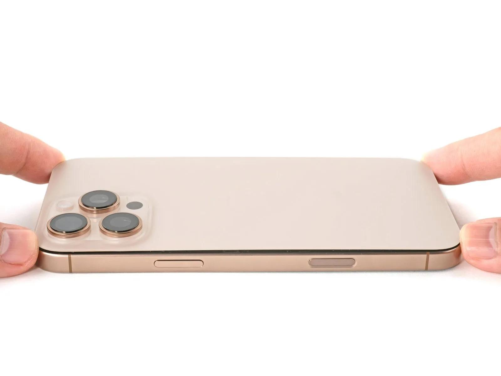
iPhone 16 Pro Max Bottom Microphone Replacement
Detailed instructions for removing and installing the lower microphone assembly on an iPhone 16 Pro Max are provided in this document.
Voice recording problems or unreliable audio performance on your iPhone may indicate a faulty microphone necessitating replacement.The component responsible for capturing audio is referred to as the microphone.To ensure a secure and waterproof seal after the repair, new back glass adhesive is essential.
- A replacement microphone adhesive gasket is also required, particularly if the new microphone lacks a pre-applied gasket.
- The purpose of the gasket is to provide a tight seal around the microphone.Proper sealing is critical to prevent water ingress and maintain device functionality.Failure to properly adhere the microphone and back glass can compromise the iPhone's water resistance.
Step 1 | Before you begin
- To mitigate potential safety risks associated with charged lithium-ion cells, permit your iPhone's battery to discharge to a level below 25% capacity.
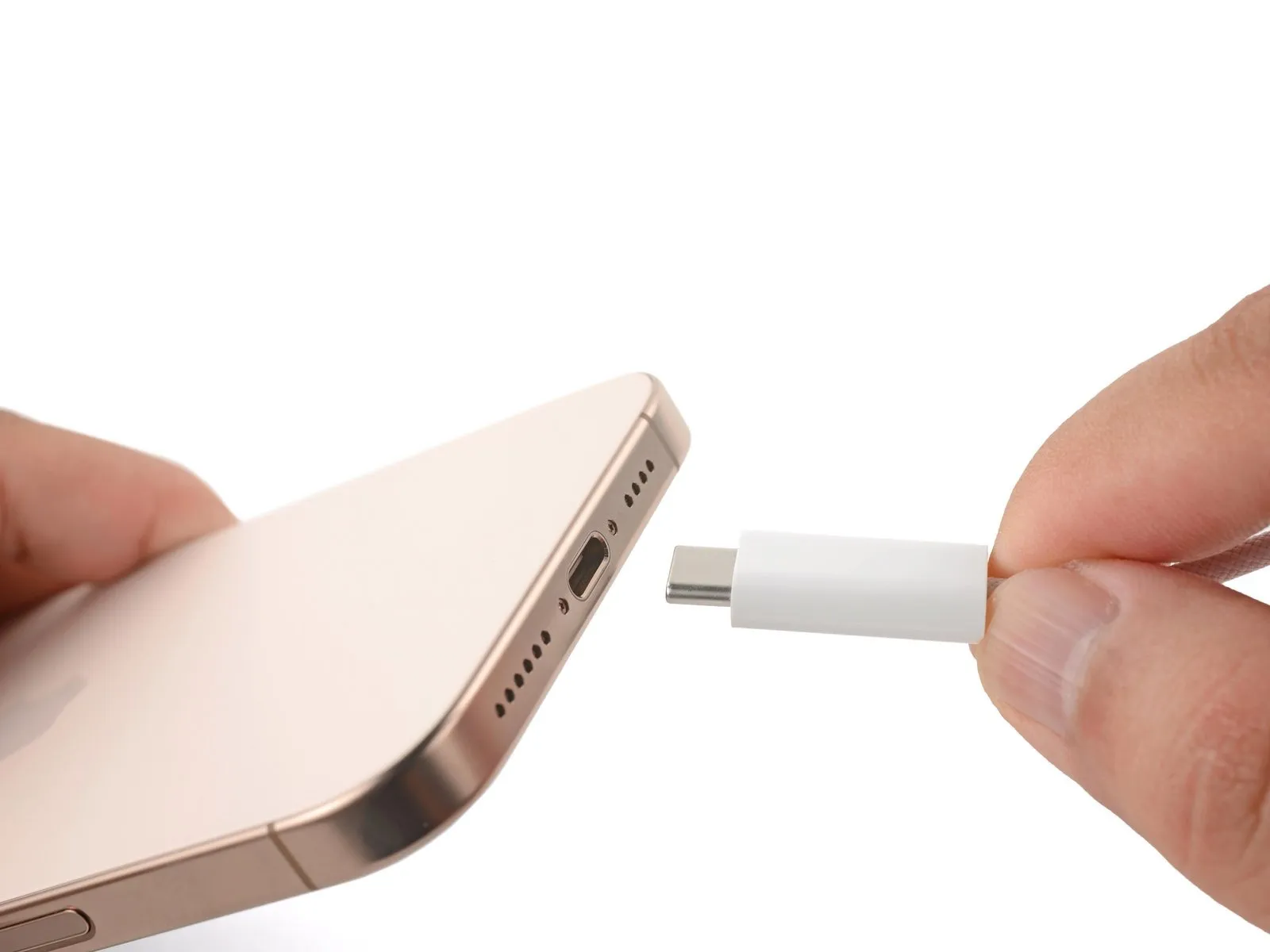
- Disconnect all connected cables from the iPhone device prior to proceeding with any repair steps.
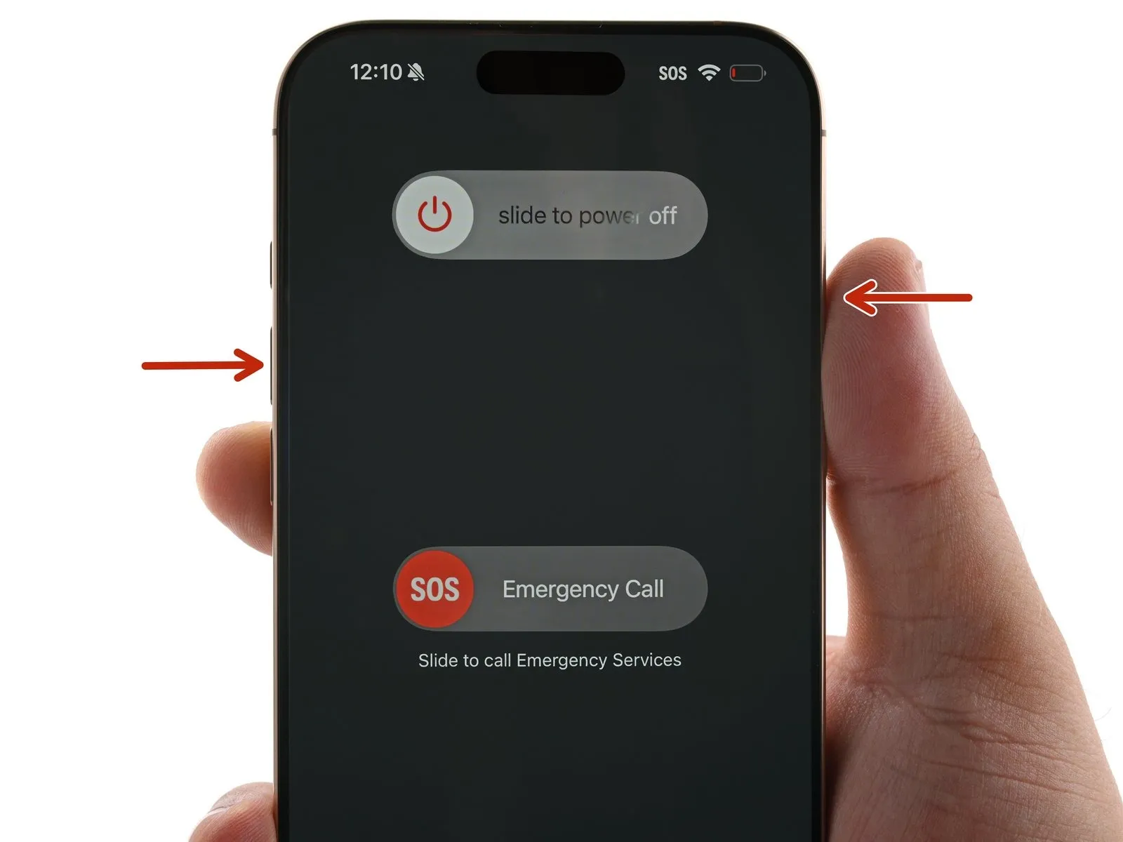
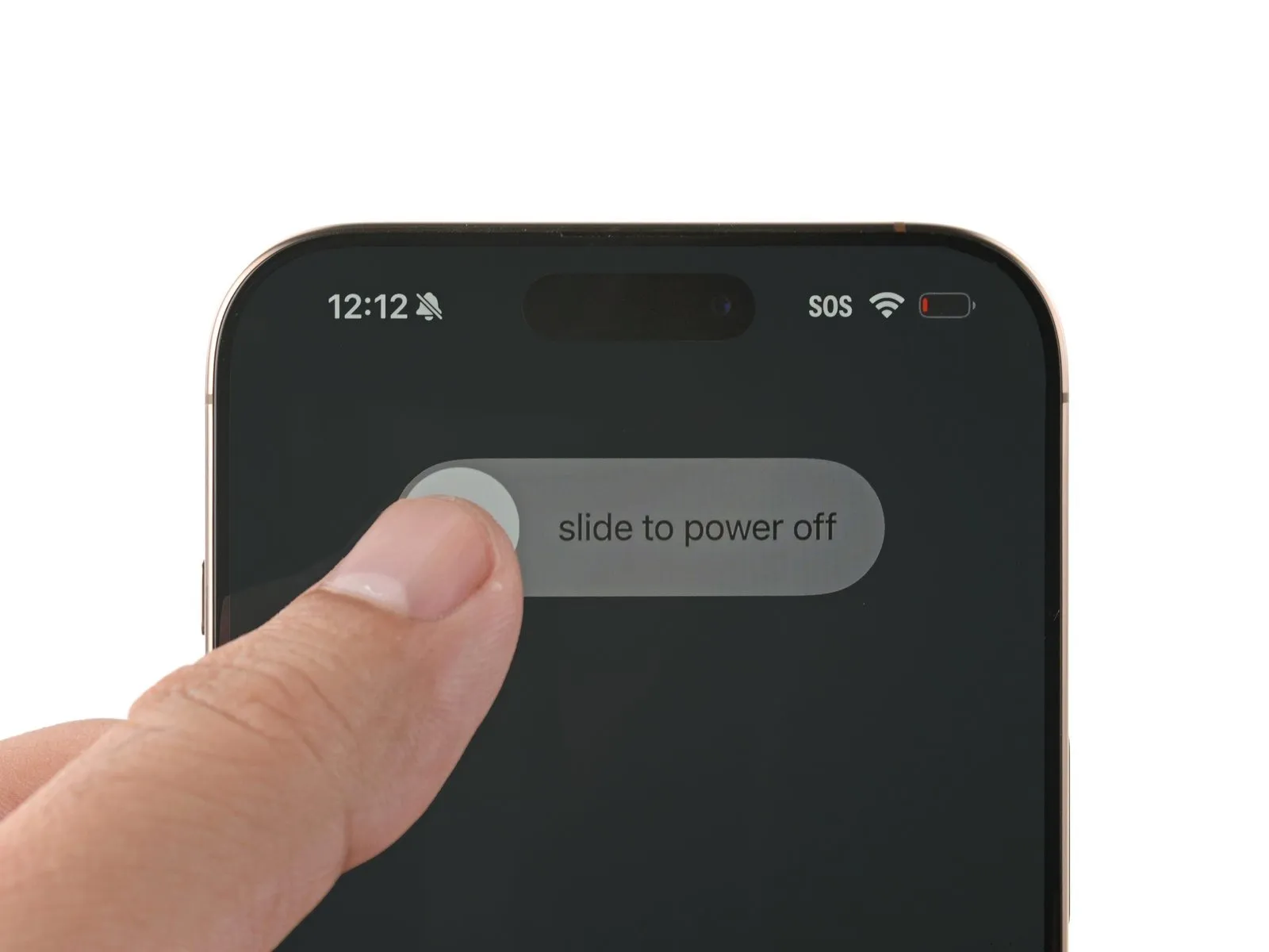
- Simultaneously depress the power button and either volume button, then utilize the on-screen slider to initiate the power-off sequence for your iPhone.
Step 2 | Tape over any cracks
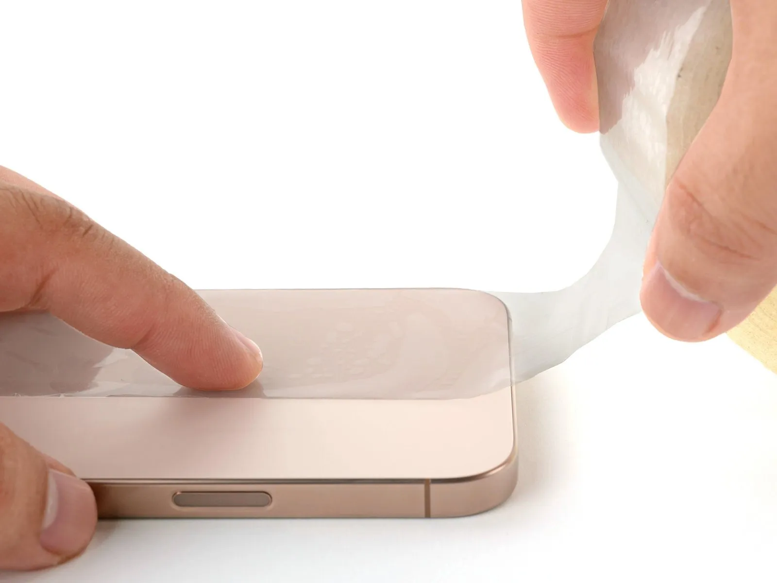
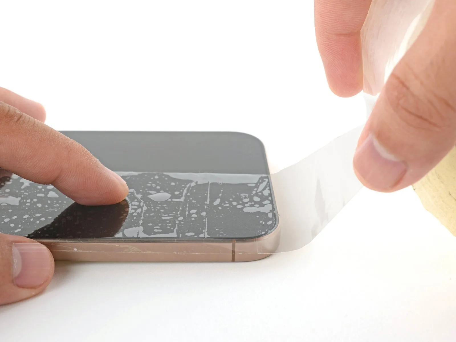
- To prevent injury and simplify the subsequent separation of components, apply multiple layers of adhesive packing tape across the fractured screen or rear glass surface.
- Ensure a sufficiently sized, uninterrupted section exists close to the lower perimeter, allowing for secure adhesion of a suction cup.
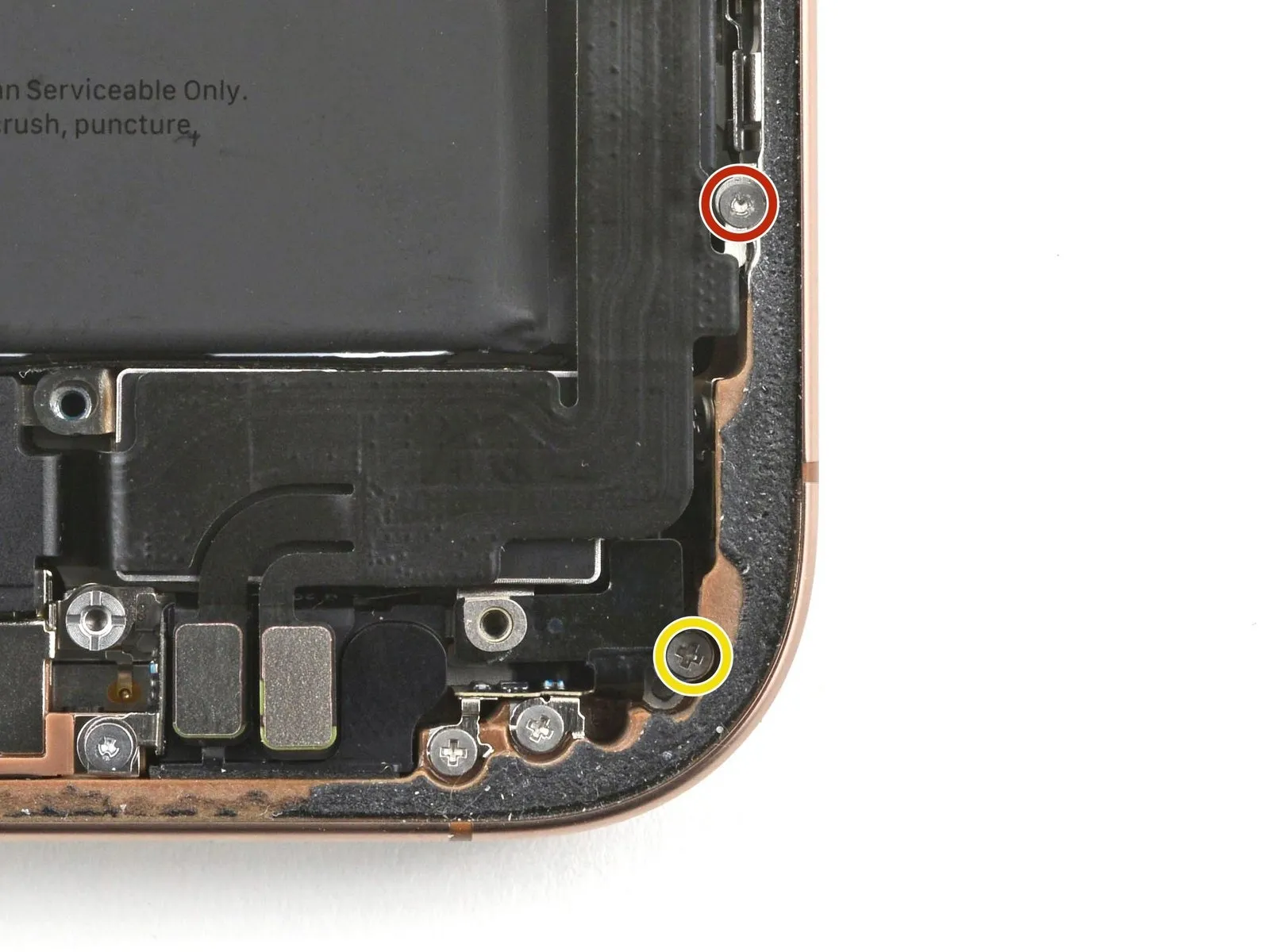
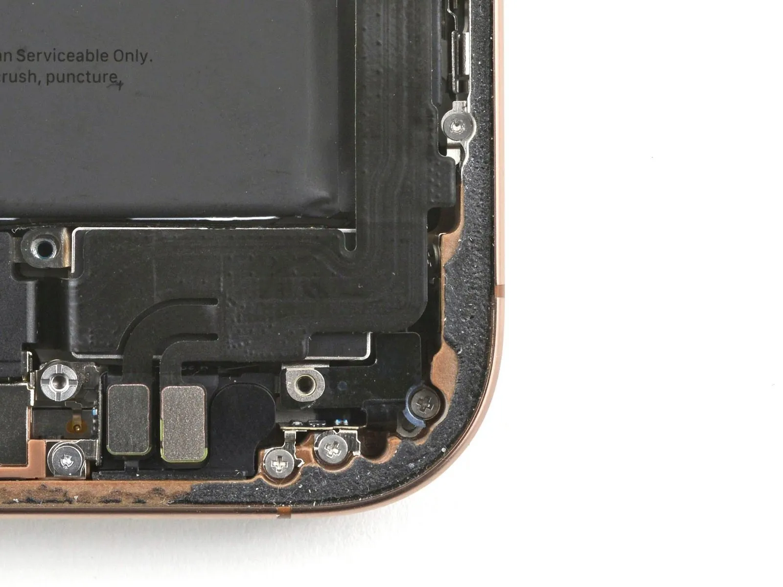
Step 3 | Remove the pentalobe screws
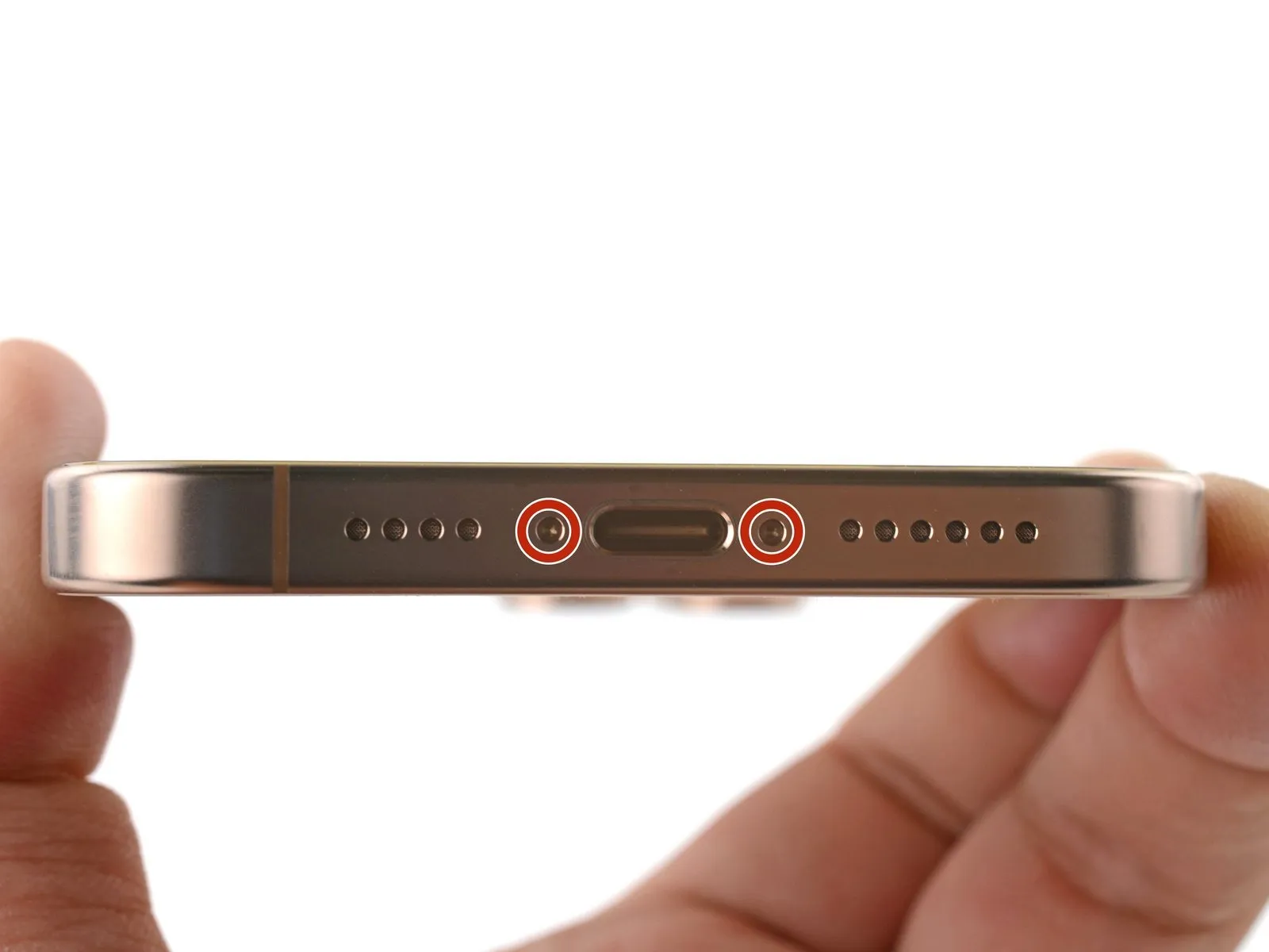

Employ a P2 pentalobe driver to detach the two screws, each measuring 7.4 mm in length, positioned laterally around the charging port.The two screws flanking the charge port must be unscrewed utilizing a P2 pentalobe driver.To facilitate removal of the screws situated on both sides of the charge port, a P2 pentalobe driver is required; these screws are each 7.4 mm long.
Step 4 | Mark your opening picks


- Caution: Improper insertion of a pick tool can result in device damage.To avoid potential harm to your device, a marking procedure is recommended.
- Establish a reference point on the pick to limit insertion depth.
- Using a measuring tool, determine a distance of precisely 3 millimeters.Apply a permanent marking material to the pick's tip at the measured 3 mm location.For enhanced precision, consider marking additional corners with varying distances.
- As an alternative method, affix a coin to the pick's tip, ensuring a 3 mm offset.
- This modification serves to restrict the pick's insertion depth and safeguard the device.
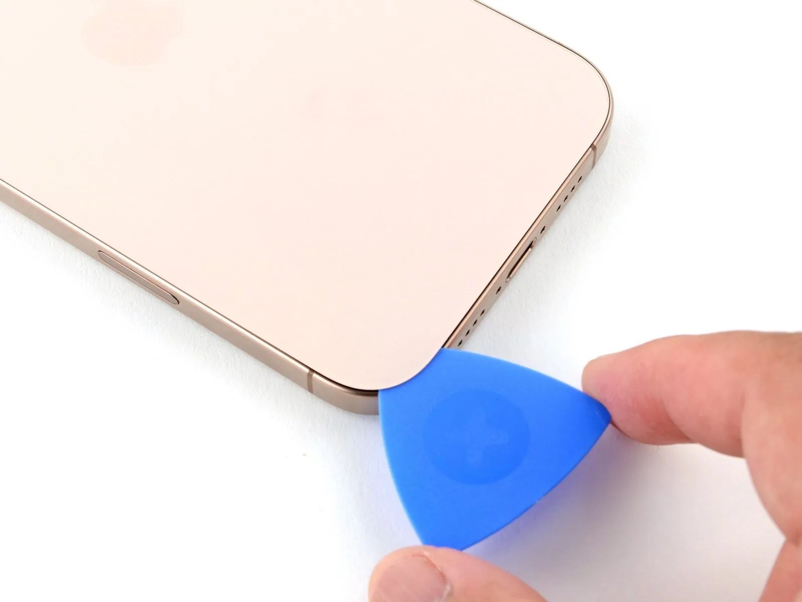
Step 5 | Create a gap using a suction handle
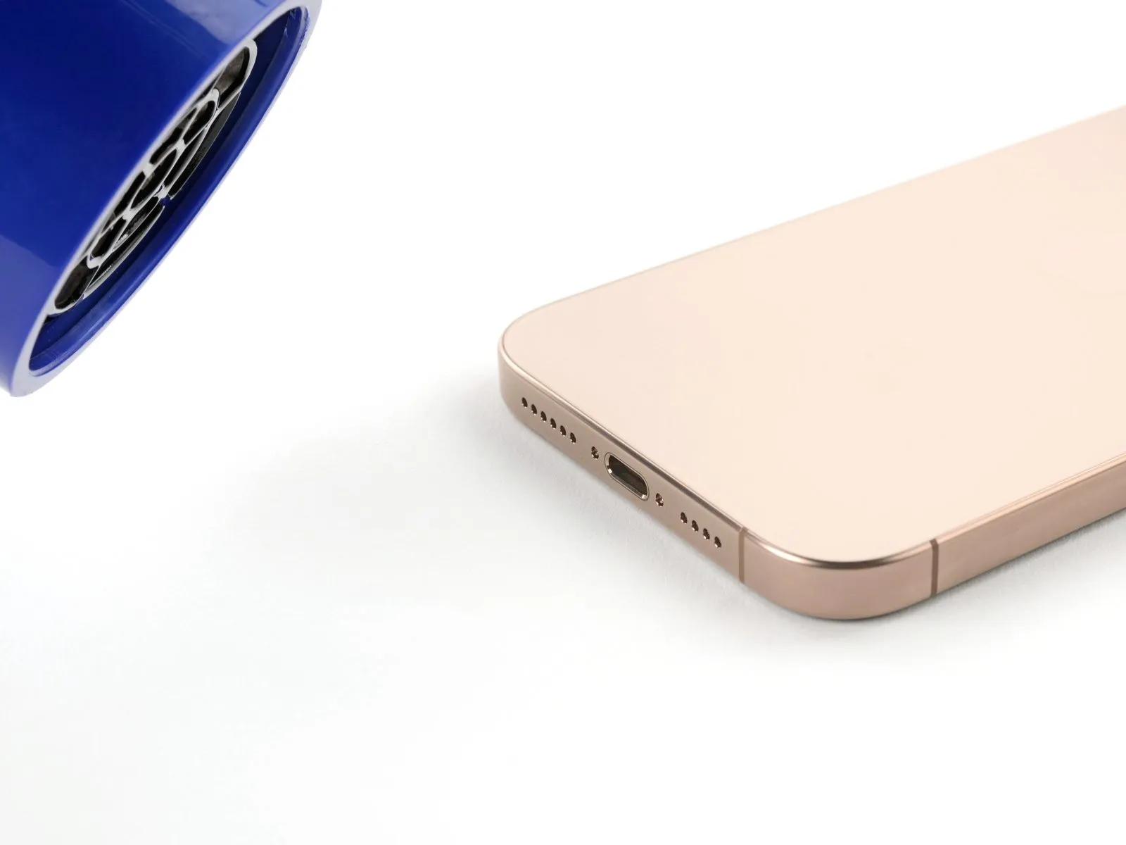
- Employing a hair dryer or heat gun, warm the lower perimeter of the rear glass panel until it reaches a temperature that is comfortably felt upon contact.
- Alternatively, an iOpener can be utilized for localized heating; adhere to the provided guidelines for correct heating and application of the iOpener.
Step 6


- Secure a suction handle to the lower perimeter of the rear glass panel.
- Exert consistent, considerable upward pressure on the handle to separate the back glass from the device's frame.
- Should separation not occur initially, increase the heat applied to the edge and repeat the lifting process.
- Carefully introduce the pointed end of a prying tool into the newly formed space.
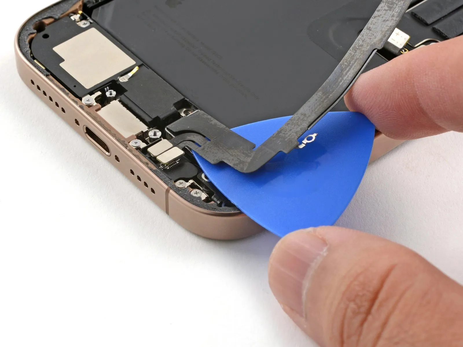
Step 7 | Back glass information
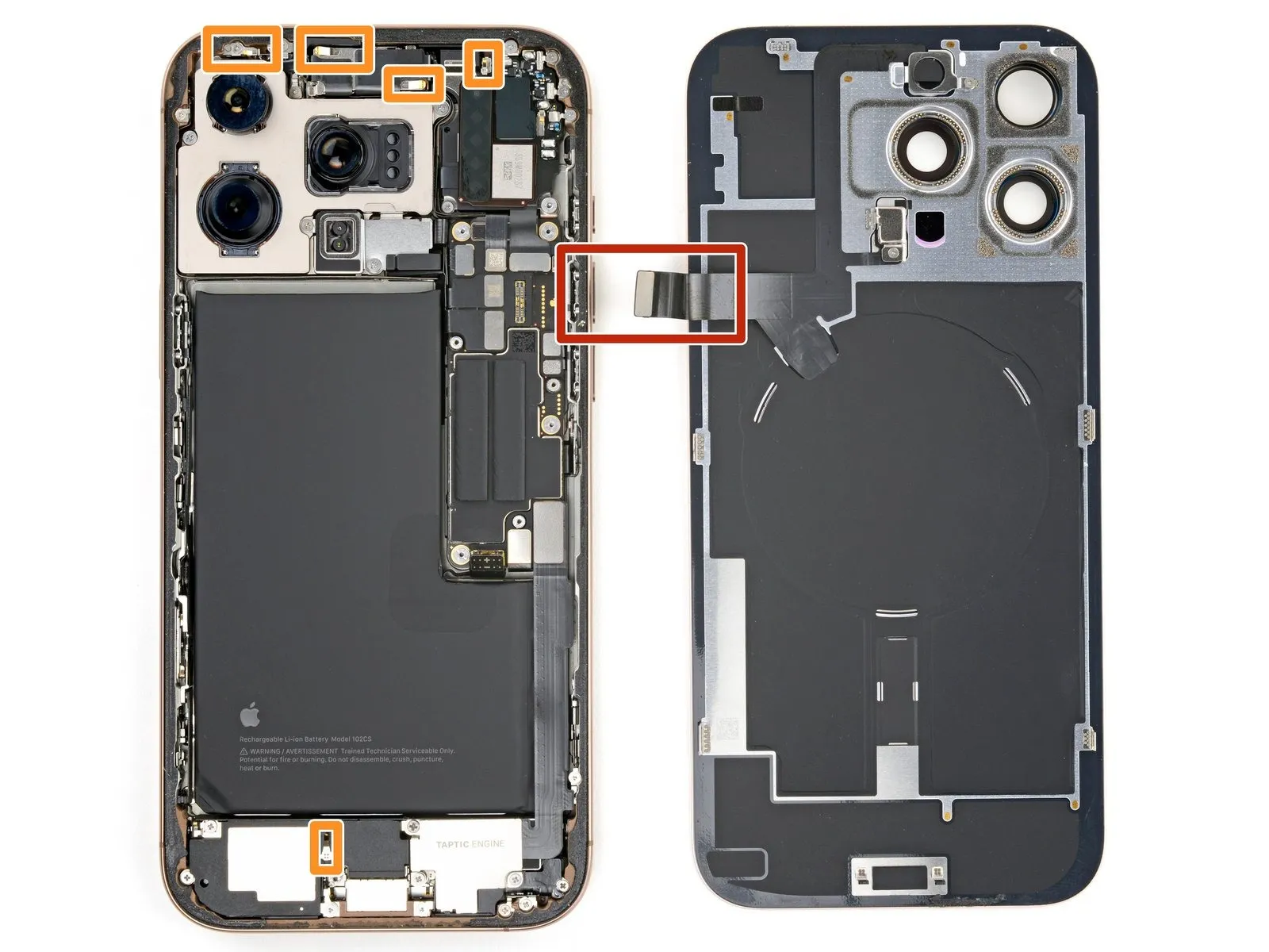
- During the process of separating the rear glass with a separation tool, maintain a maximum insertion depth of 3 millimeters to prevent potential harm to adjacent components.
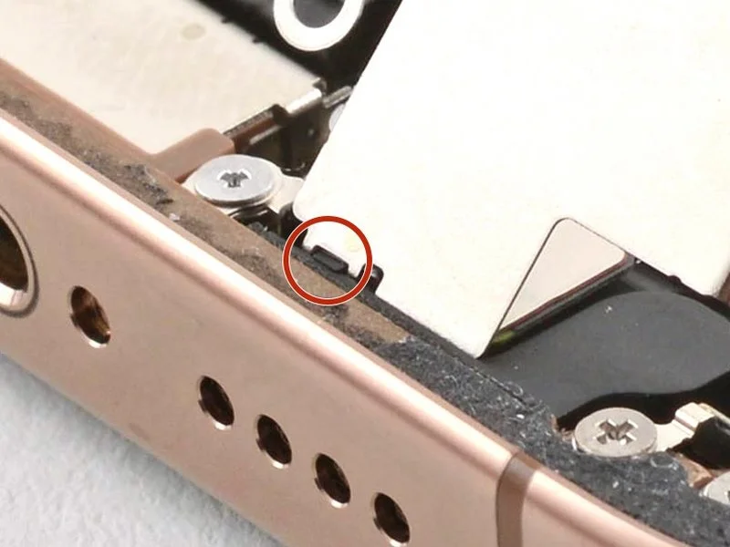
- A fragile connector, situated near the volume up button, links the rear glass assembly to the iPhone's internal circuitry; exercise caution to prevent severance of this cable during separation.
- Several spring-based electrical contacts are positioned along the iPhone's outer edge and should be avoided during the glass separation procedure.
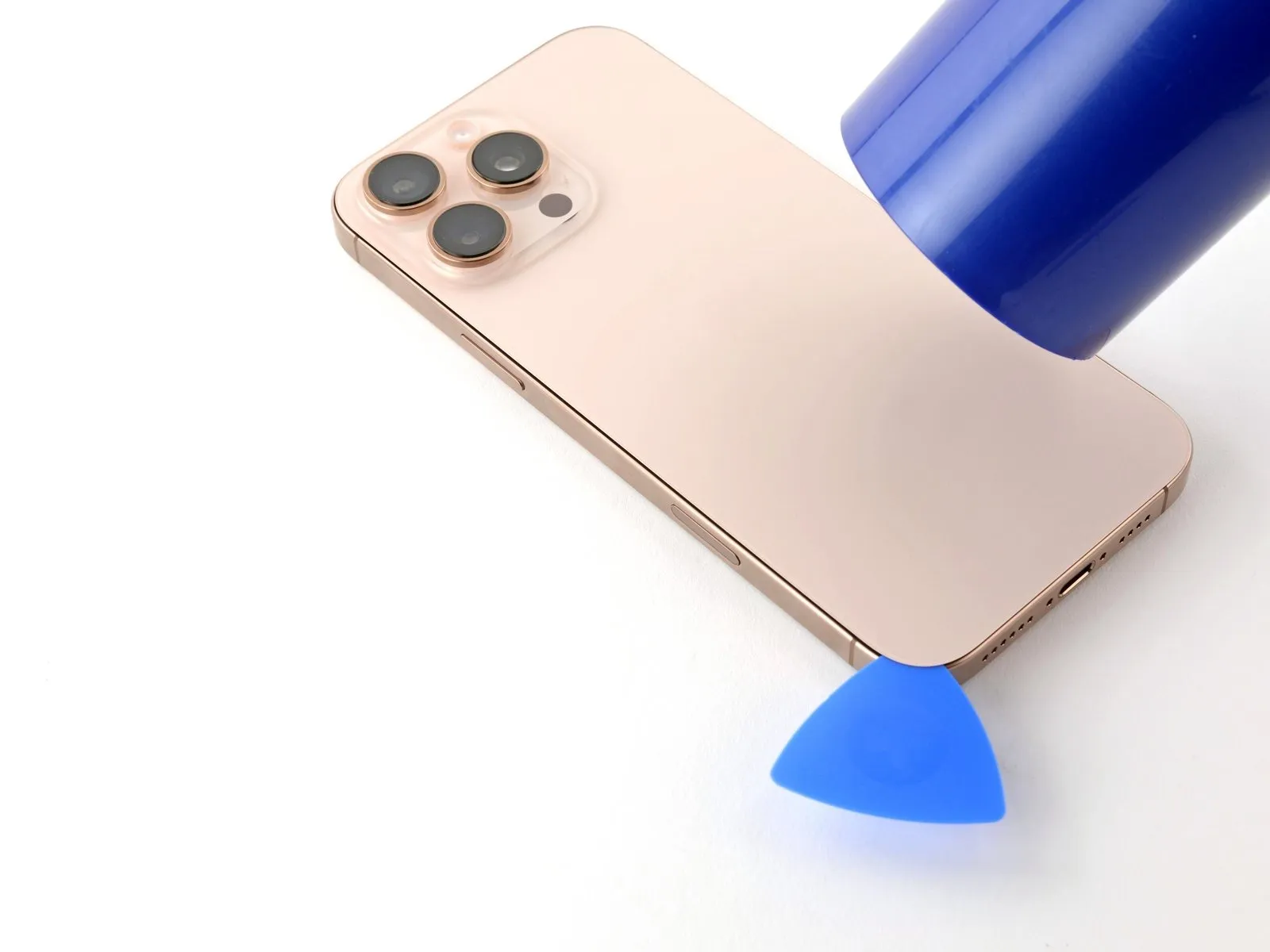
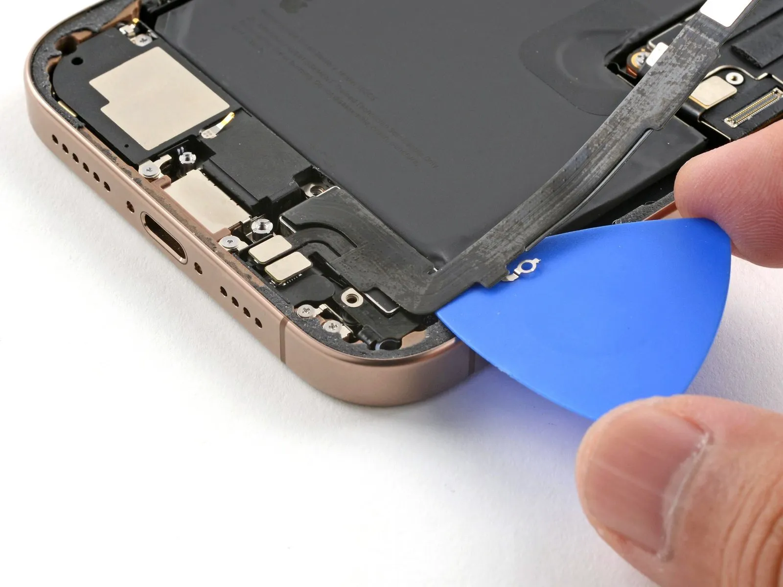
Step 8 | Separate the bottom edge adhesive

- Utilize the opening pick, moving it along the lower border, to sever the bonding agent.
- Should the adhesive present resistance to separation, apply heat to the edge for approximately one minute, then attempt the process anew.
- Maintain the opening pick's position within the lower-left corner to inhibit the adhesive's reformation.
Step 9 | Heat the left edge
Applying warmth with a hair dryer or heat gun to the left-hand perimeter of the rear glass panel is necessary.Elevate the temperature of the glass edge by directing heat until a tactile sensation of warmth is detected.This heating process facilitates separation of the back glass from the device's frame.
Step 10 | Separate the left adhesive

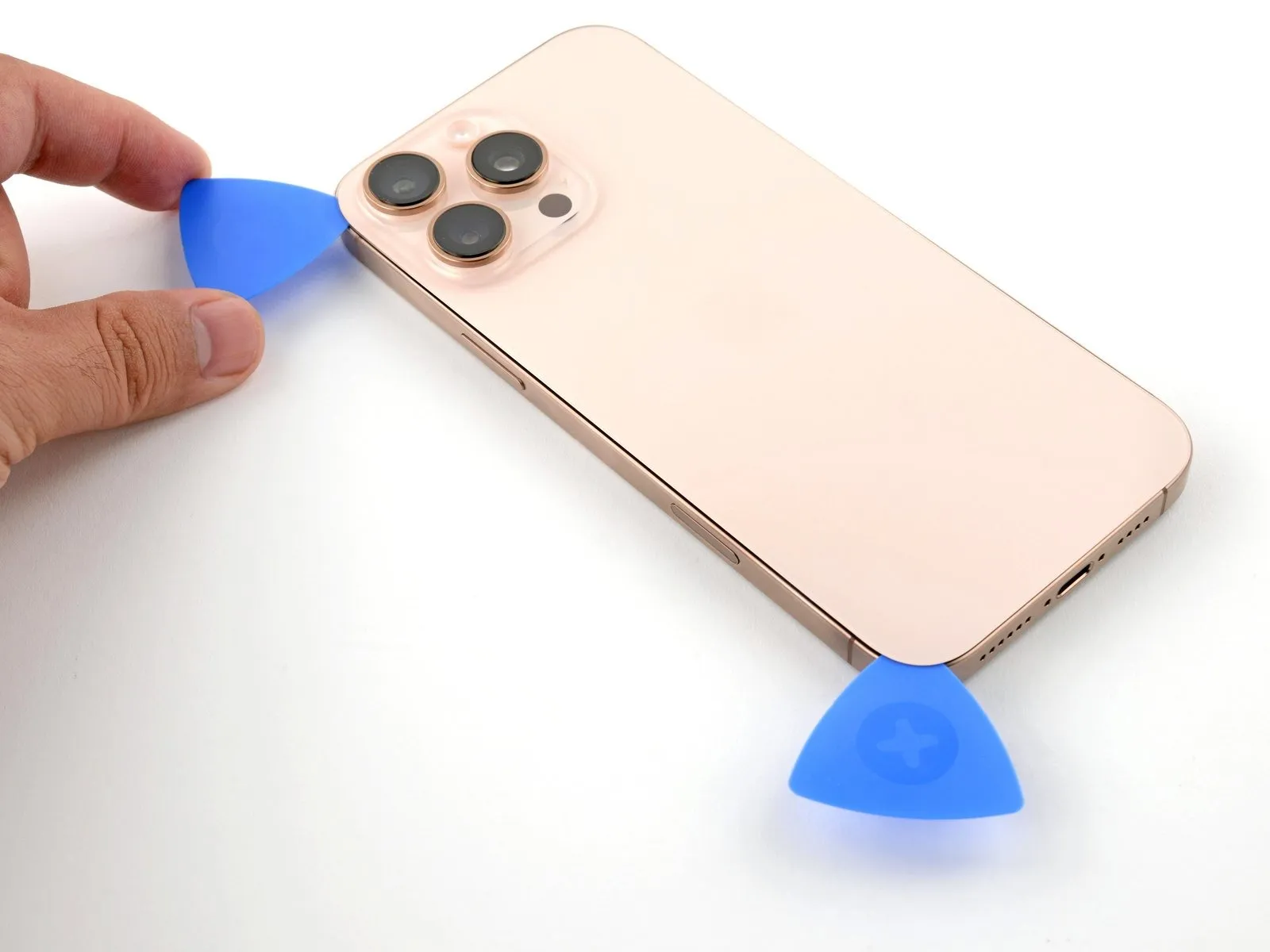
- Introduce a supplementary opening tool into the lower-left portion, positioned near the already inserted tool.
- Ensure the tool's insertion depth remains below 3 mm to safeguard the spring contact points from harm.
- Move the tool along the left side to detach the adhesive bond and free the metal fasteners.
- An audible and tactile indication of the metal fasteners disengaging will be noticeable during this movement.
- Maintain the initial tool's placement in the upper-left area to obstruct the adhesive's potential to reattach.
Step 11 | Heat the top edge and corner

Apply warmth to the upper edge and upper-right section of the rear glass panel using a hair dryer or heat gun, ensuring the surface reaches a temperature that is noticeable upon contact.The application of heat softens the adhesive securing the back glass, facilitating its removal.Maintain a safe distance and avoid prolonged heat exposure to prevent damage to surrounding components.
Step 12 | Separate the top adhesive

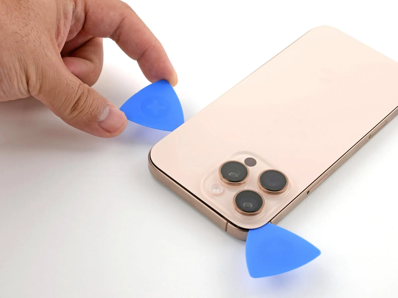
- To preclude harm to the spring contacts, ensure the insertion depth of the tool remains no greater than 3 millimeters.Introduce a third specialized tool through the upper-leftmost aperture.Advance the tool across the superior boundary and around the upper-right corner, pausing directly over the 'volume up' control.
- Maintain the placement of this tool to inhibit the adhesive from reforming a bond.
- Exceeding a depth of 3 mm risks compromising the integrity of the spring contact points.
- Positioning the third tool at the top-left corner facilitates subsequent manipulation.
Step 13 | Heat the right edge

Step 14 | Separate the right adhesive


- Position a fourth opening tool within the lower-rightmost section.
- Maneuver the opening tool along the corner's contour and upward along the right side, pausing its movement just beneath the volume down button.
Step 15 | Reposition the back glass

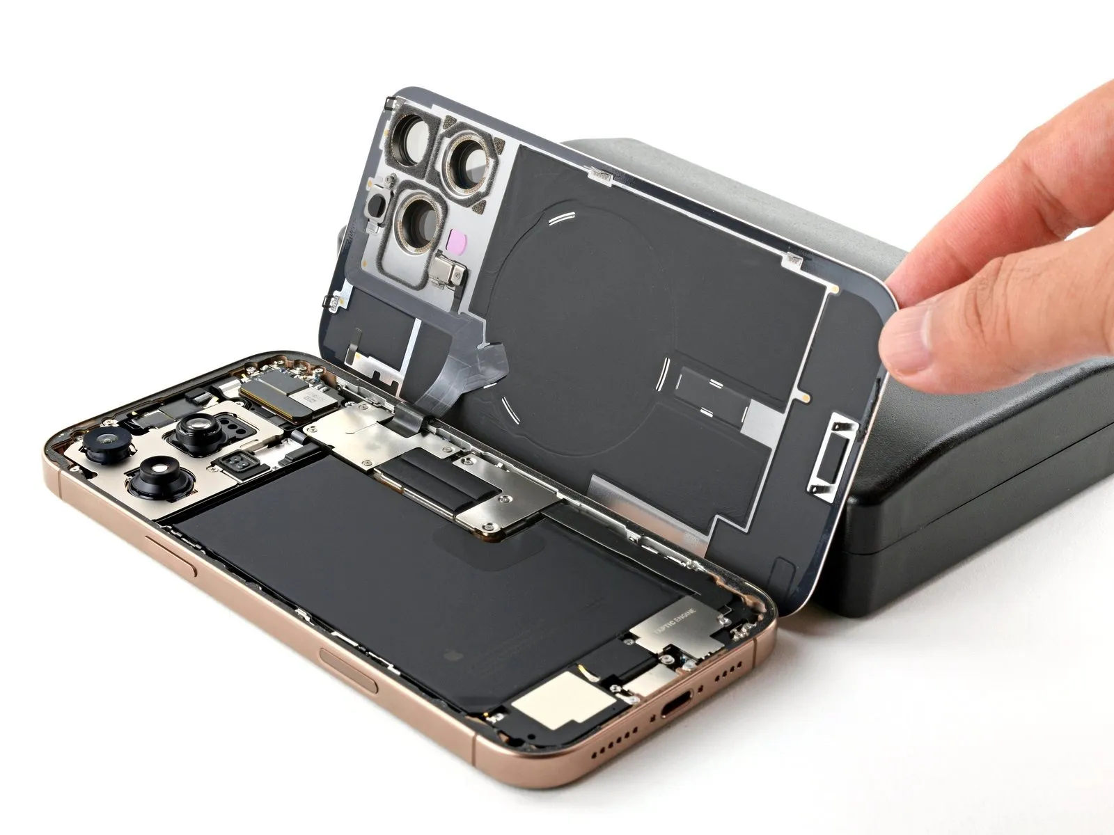
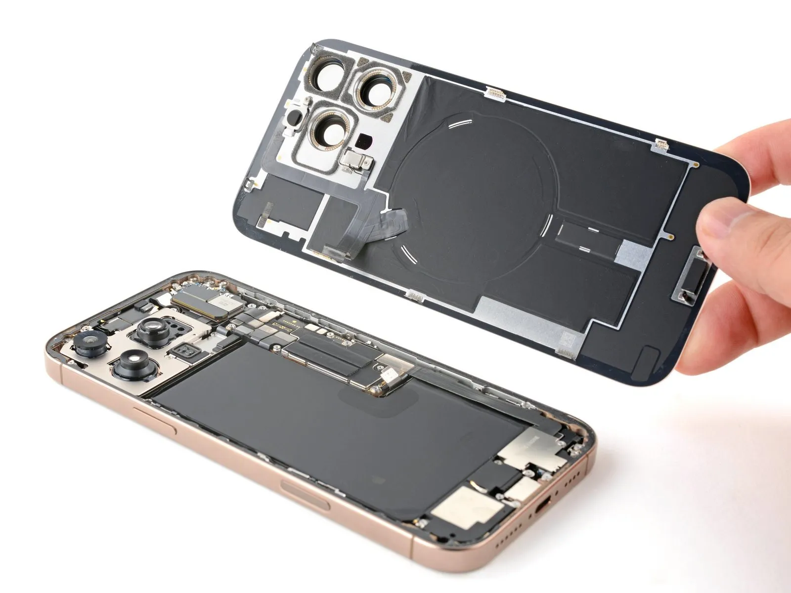
- Carefully pivot the detached back glass to the right side of the iPhone, facilitating the breaking of the remaining adhesive bond.
Step 16 | Remove the battery connector cover

- The cover utilizes two screws, each measuring 1.3 millimeters in length.
- A single screw, with a length of 1.0 millimeters, is also part of the securing mechanism.
Step 17

Step 18 | Disconnect the battery
Step 19 | Remove the back glass connector cover

- A quantity of two screws are present.These screws measure 1.3 millimeters in length.Additionally, a quantity of two screws are also present.
- These screws have a length of 1.0 millimeters.Ensure the correct driver size is used to prevent damage to the screw heads during removal.Carefully note the screw lengths as they may be used in different locations.
Step 20
Step 21 | Remove the back glass
Step 22
Step 23 | Remove the Taptic Engine cover
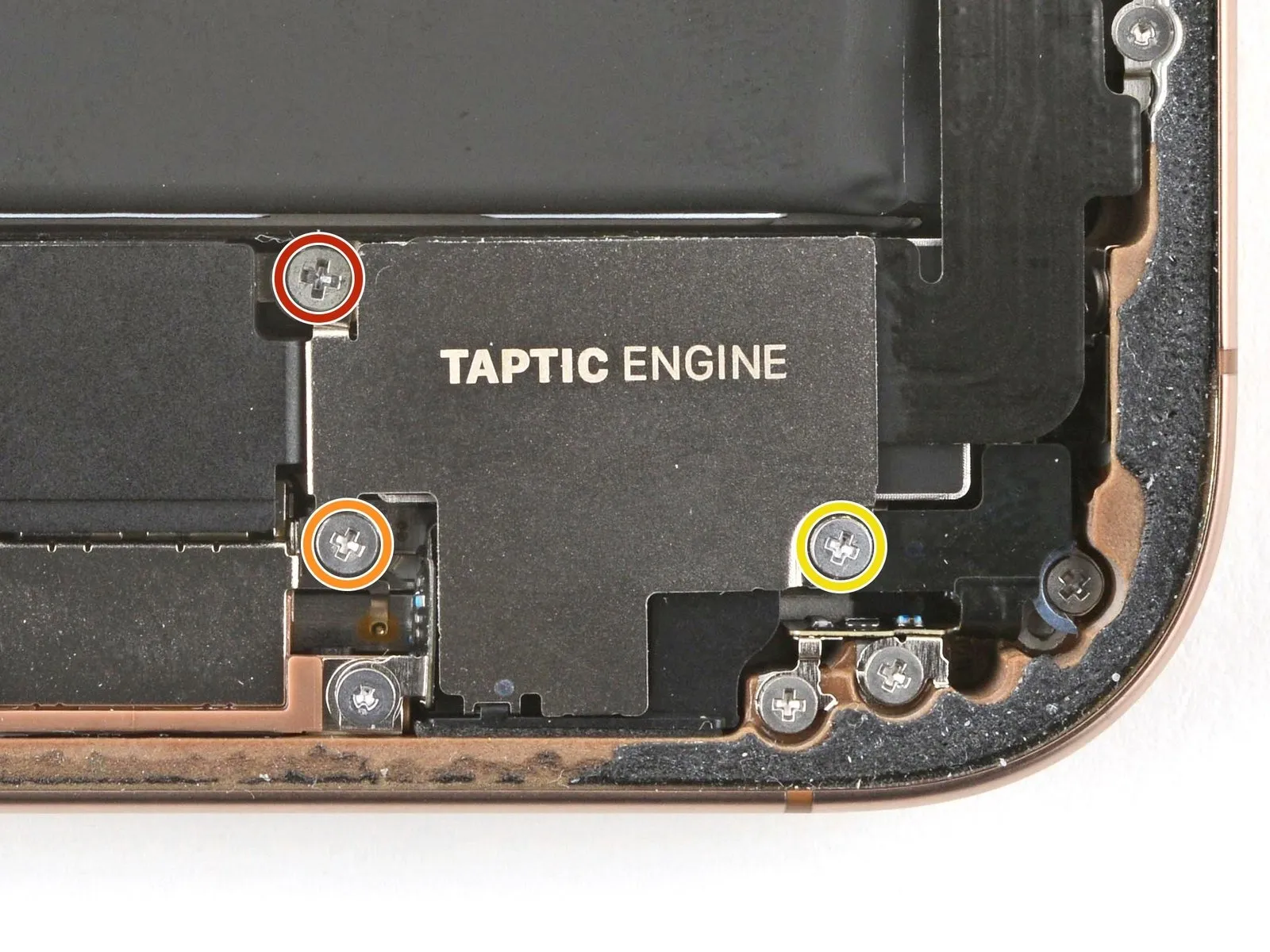

- Employ a Phillips screwdriver for the disassembly of the Taptic Engine cover, which is fastened with screws.A screw measuring 2.9 millimeters in length is among those securing the cover.Additionally, a screw with a length of 1.3 millimeters is utilized in the fastening process.
- The cover is also held in place by a screw that measures 2.4 millimeters in length.
- The three screws, each with distinct lengths, must be removed using the Phillips screwdriver.
- Carefully unscrew the Taptic Engine cover's fasteners, noting the 2.9 mm, 1.3 mm, and 2.4 mm screw lengths.
Step 24

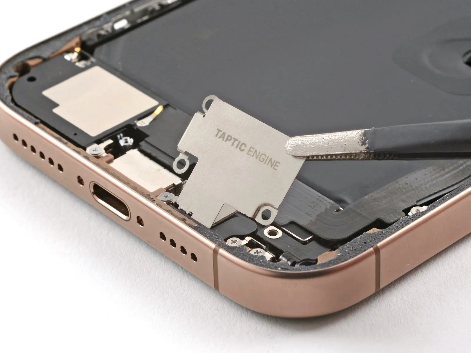

- Employ tweezers or manual dexterity to elevate the upper portion of the Taptic Engine cover.
- After the lower edge disengages from the device's frame, detach the Taptic Engine cover.
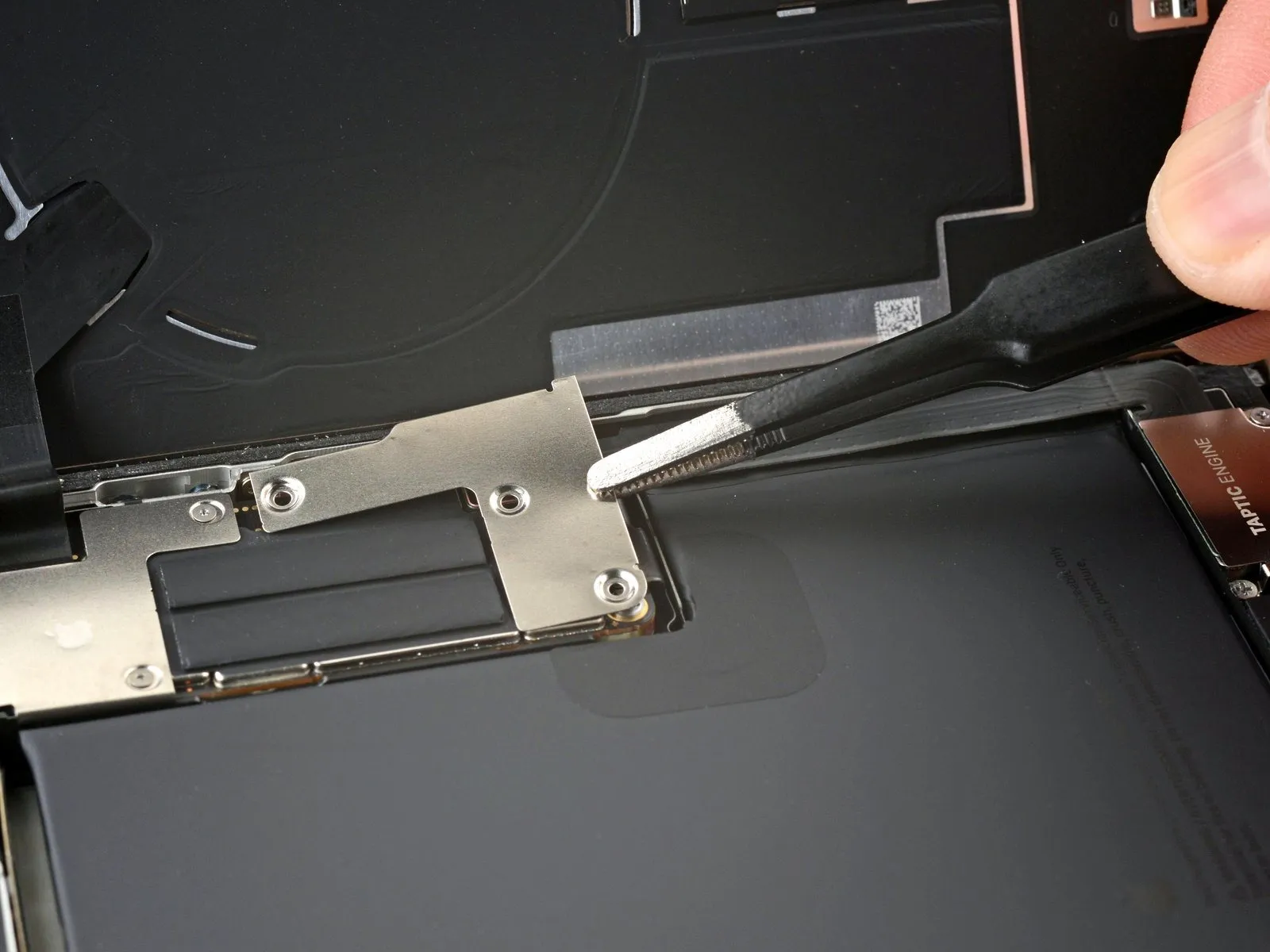
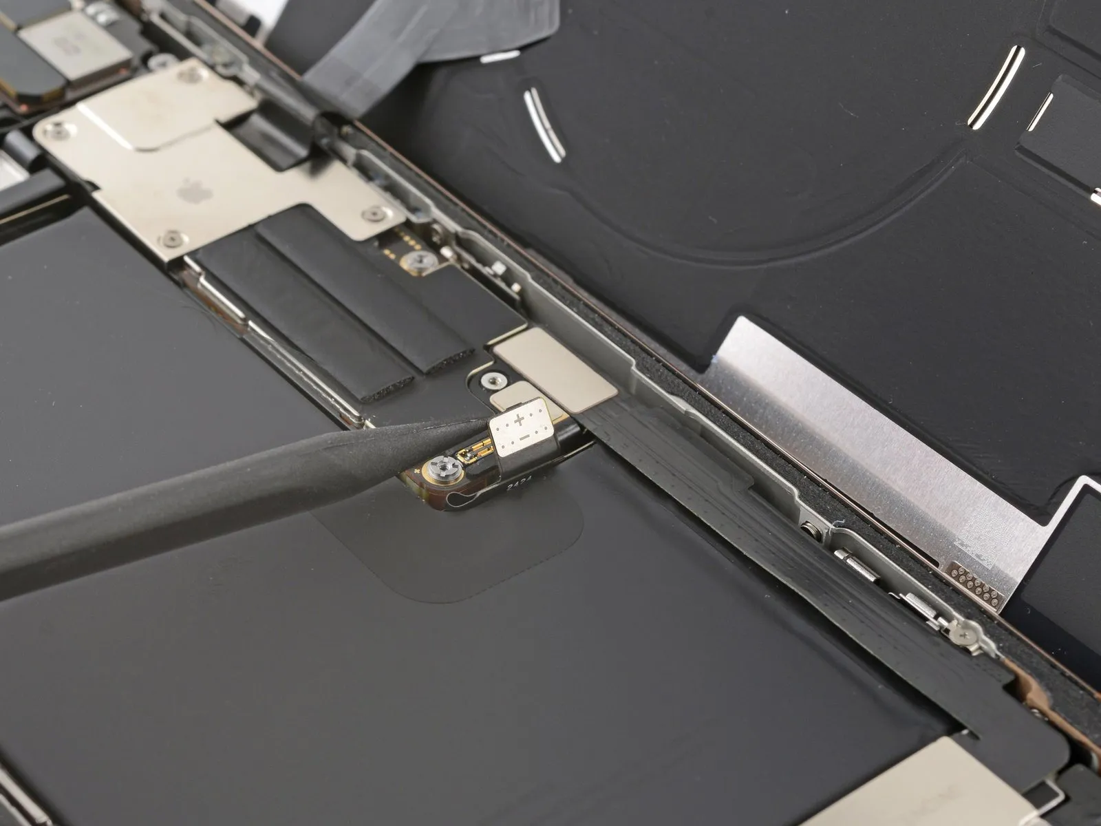
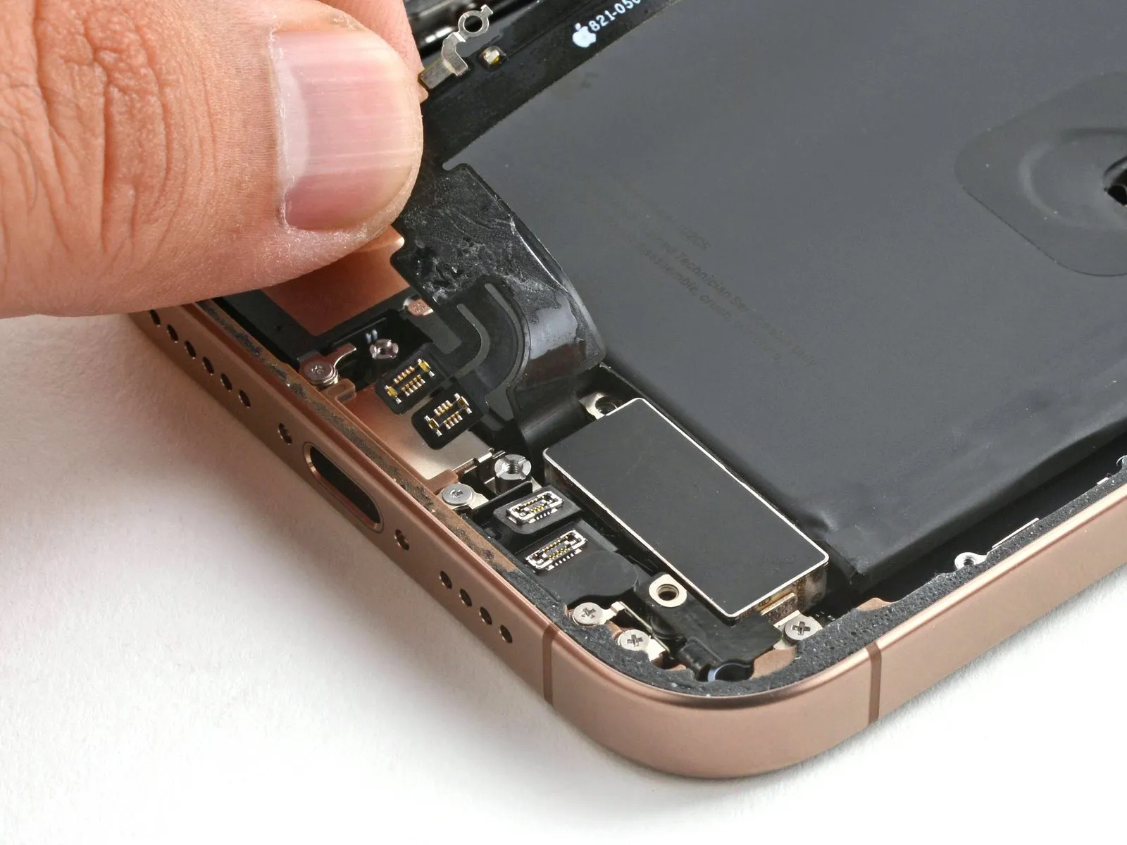
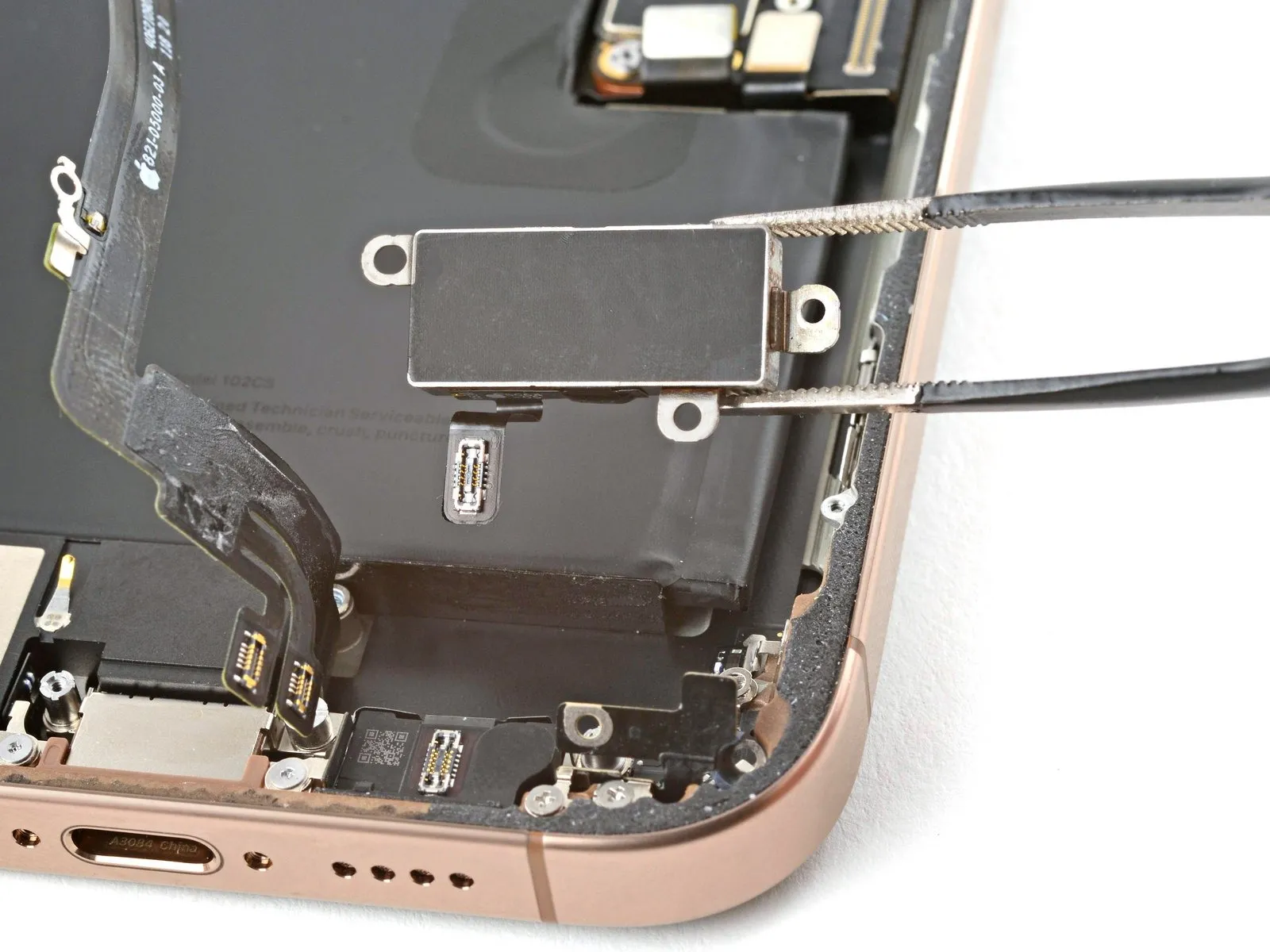
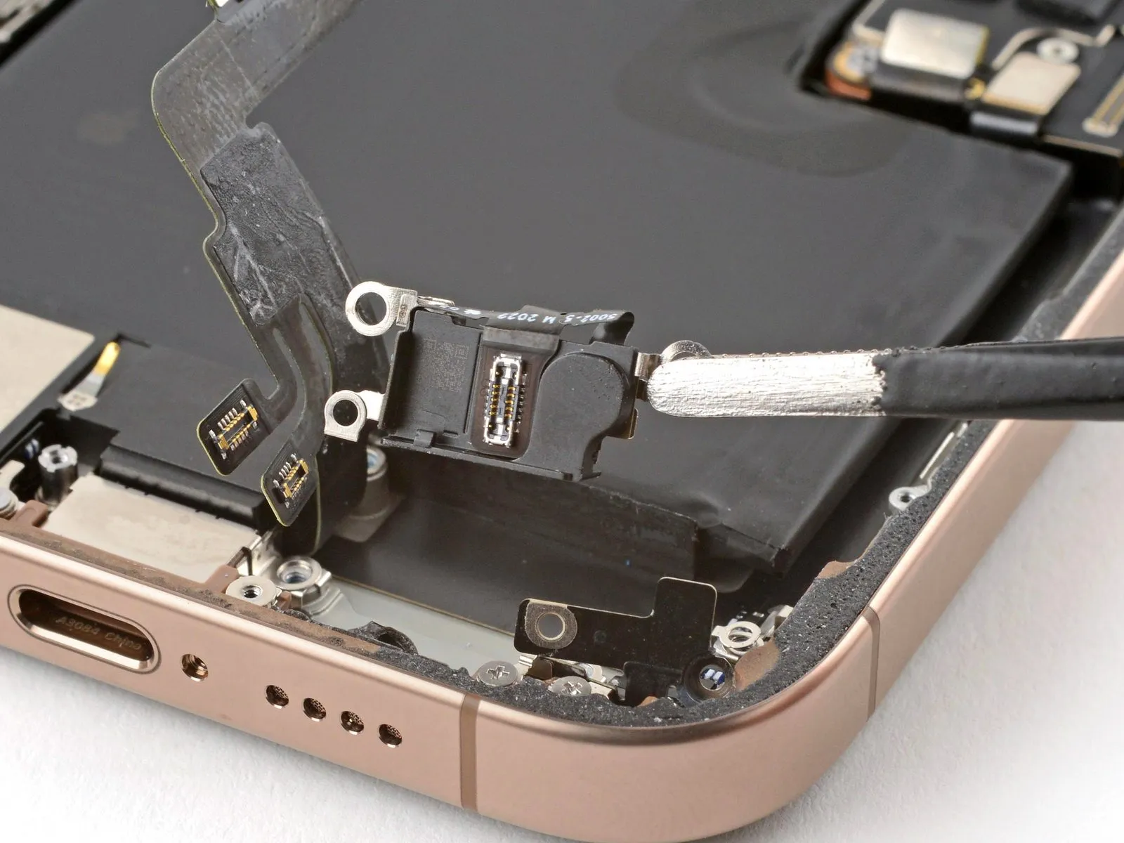
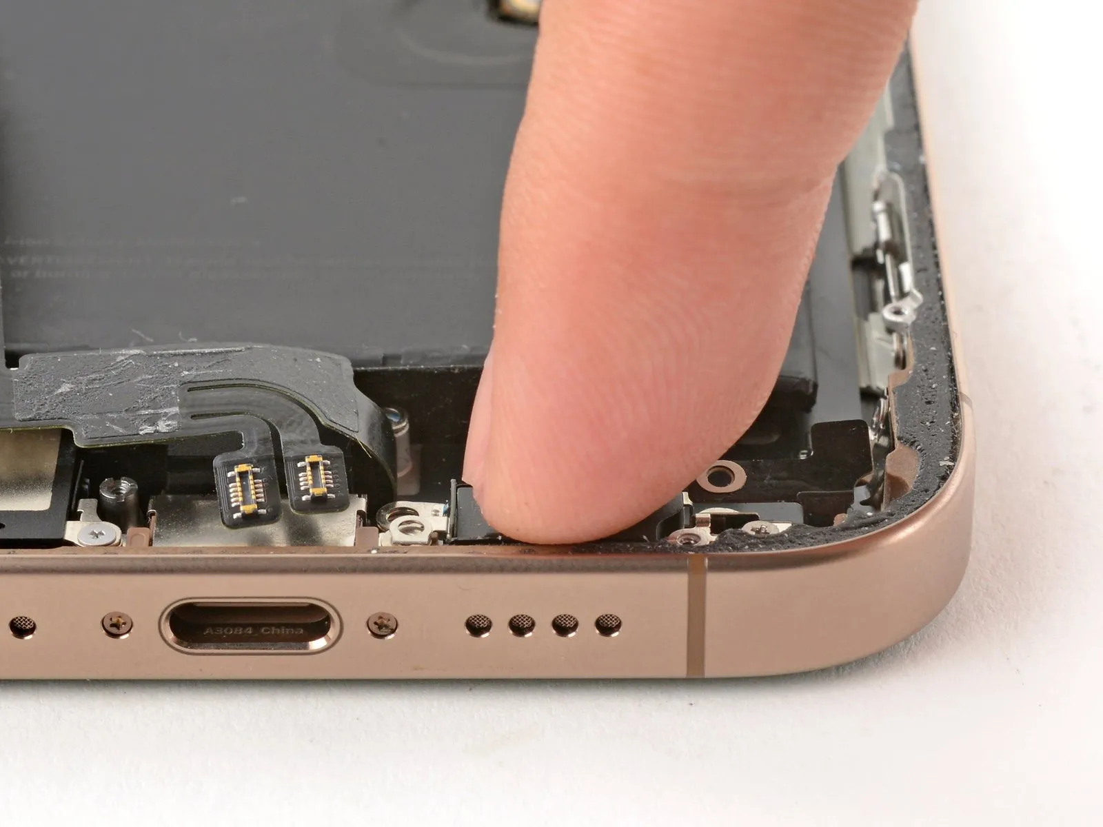
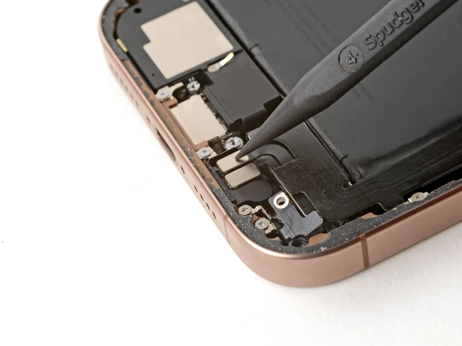
Step 25 | Loosen the lower assembly cable
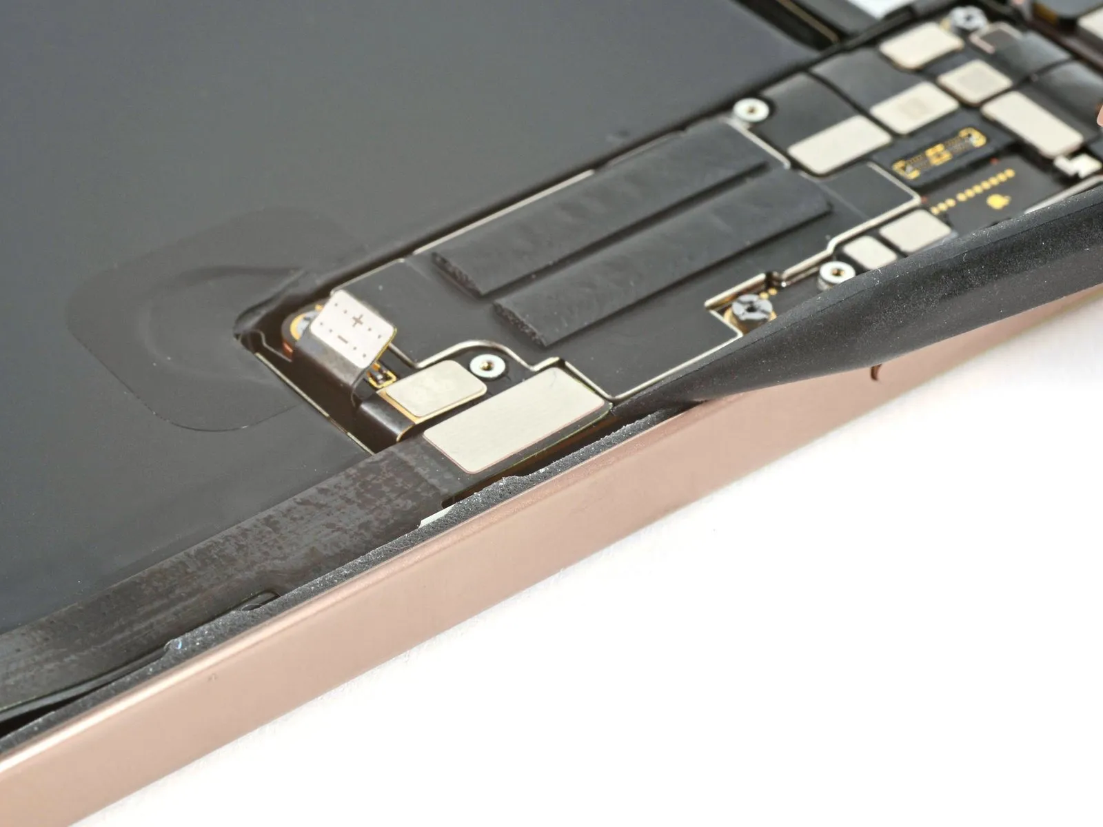
- Employ the tip of a spudger to carefully separate and detach the lower assembly cable connector from the logic board.The spudger's pointed end facilitates the release of the lower assembly cable's connection to the logic board.To release the lower assembly cable, utilize the spudger's point for prying and disconnection from the logic board.
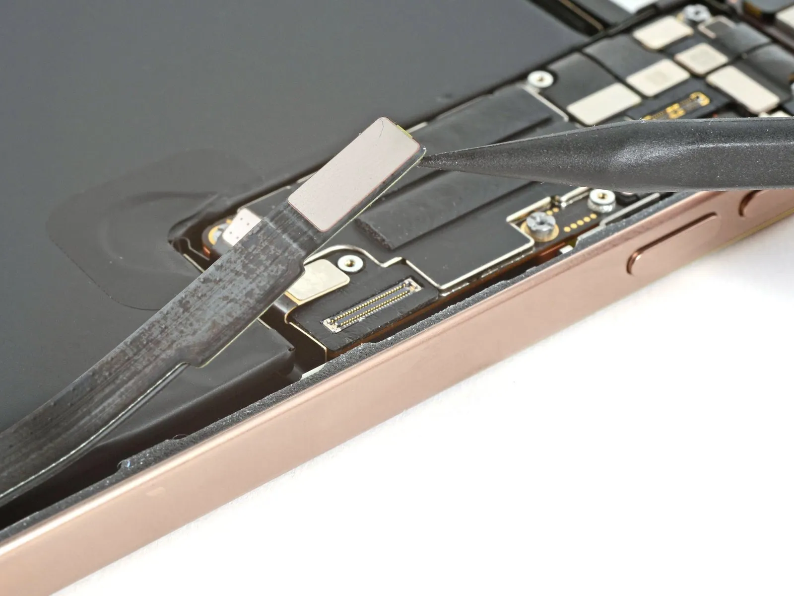
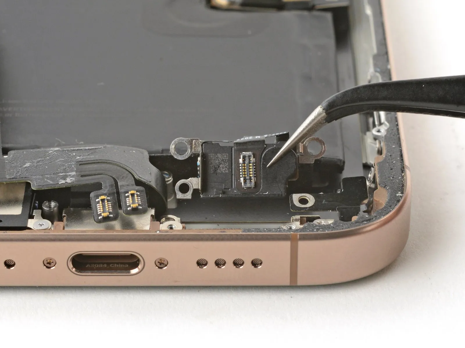
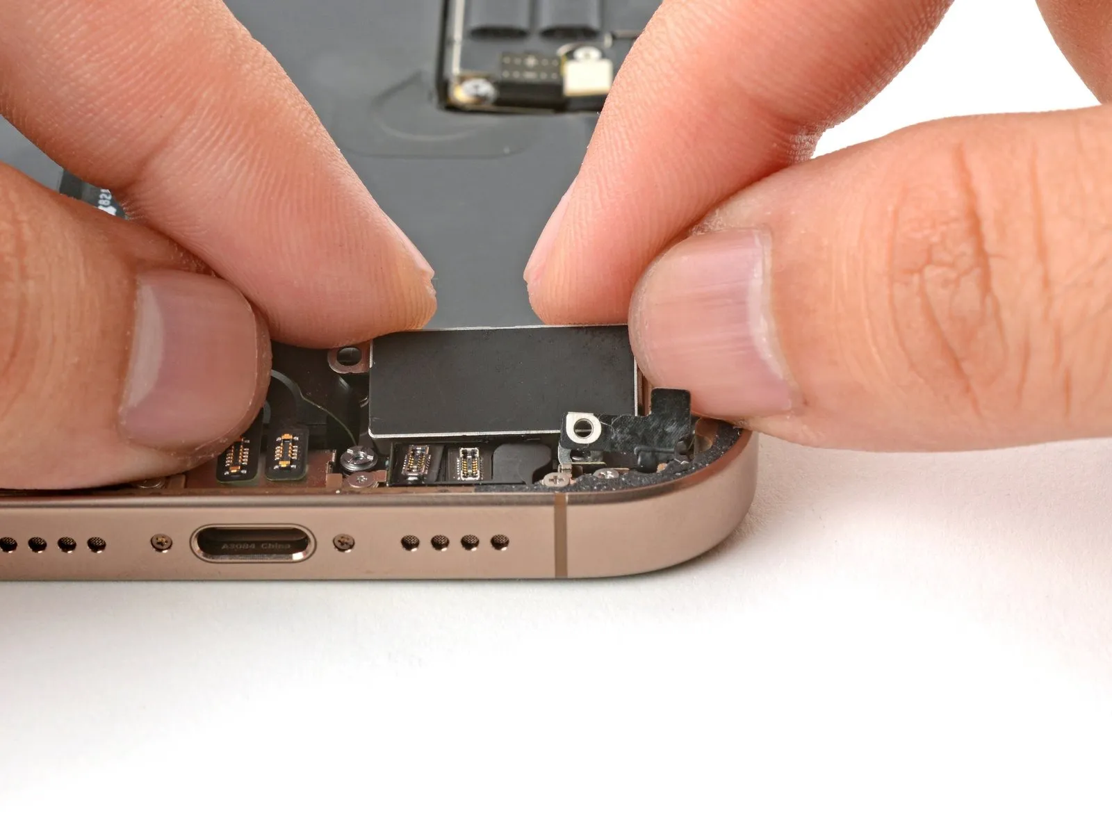
Step 26

- Employ the tip of a spudger to carefully lift and detach the pair of connectors situated close to the lower-right corner of the device's frame.These connectors are located on the bottom right edge and require separation using a spudger's pointed end.To release the connectors, apply gentle pressure with the spudger's point, ensuring disconnection from their respective sockets near the frame's lower right section.
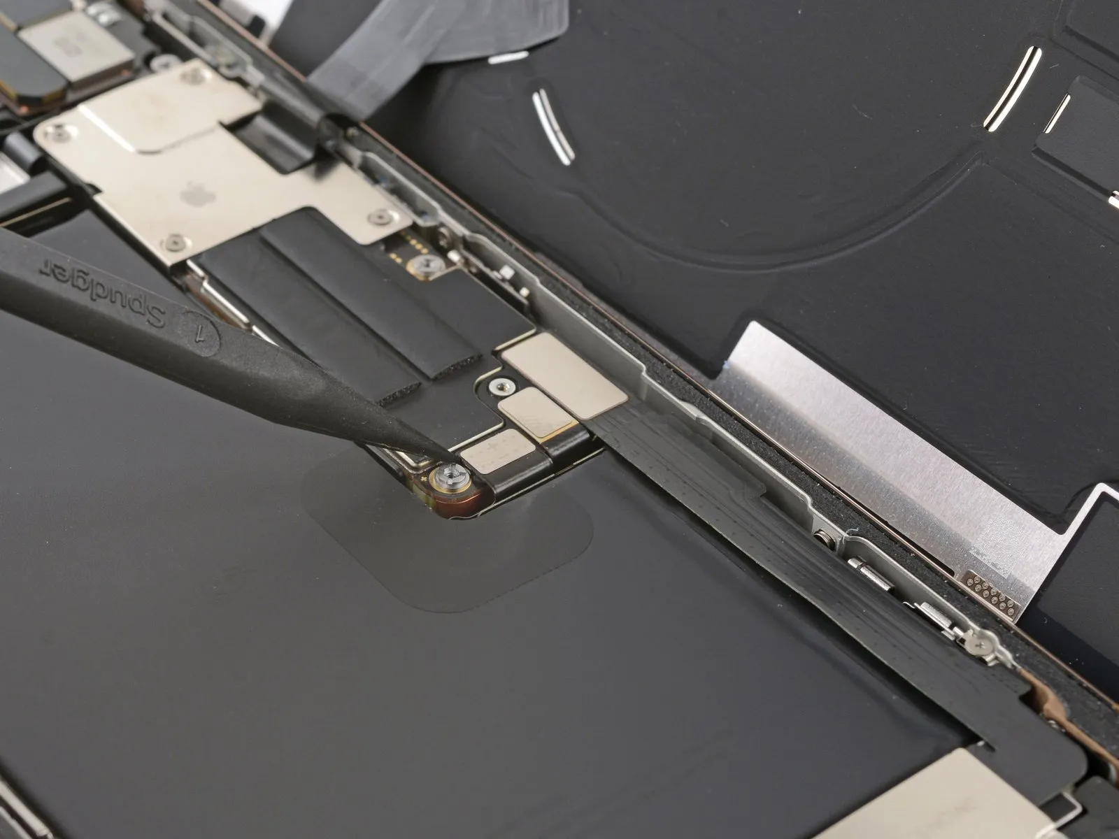
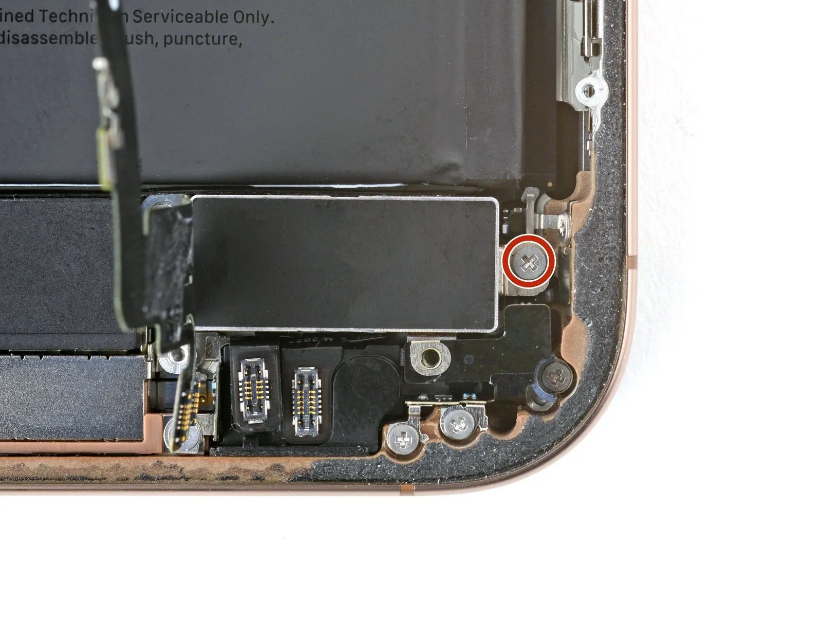
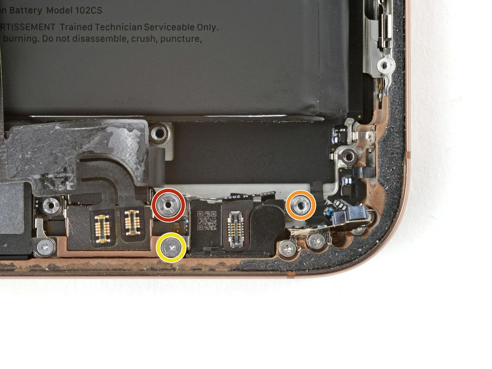
Step 27
- Detach the lower assembly cable by unscrewing the two fasteners that hold it in place.
A single tri-point Y000 screw, measuring 1.0 millimeters in length, is required for this step.Additionally, a Phillips screw, with a length of 1.3 millimeters, must also be removed.
Carefully loosen and extract both screws to free the cable.Ensure proper screw identification and storage to prevent loss or confusion during reassembly.
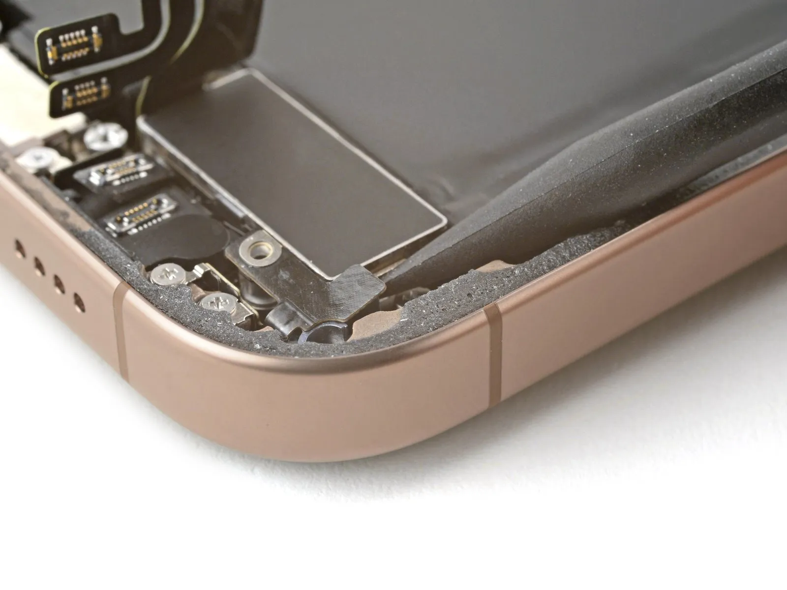
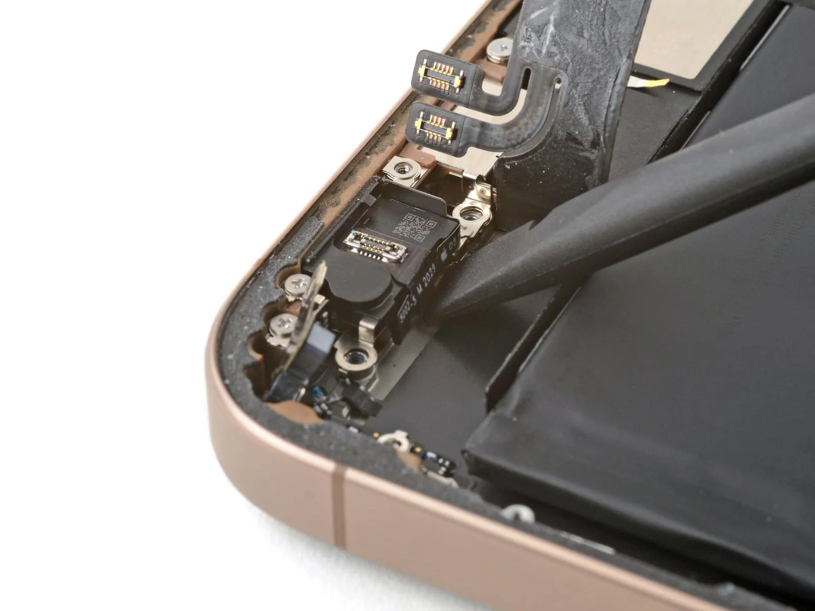
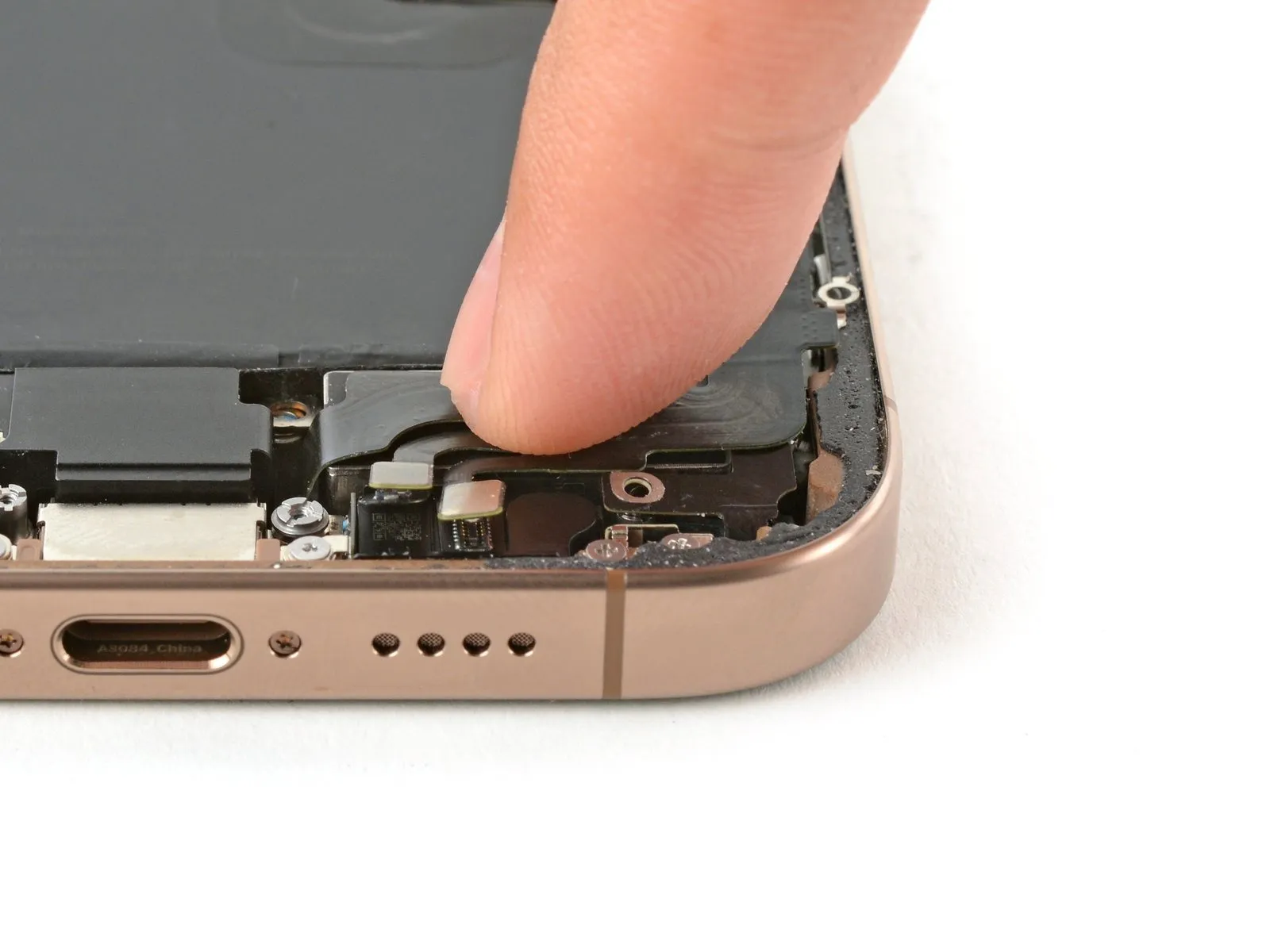
Step 28

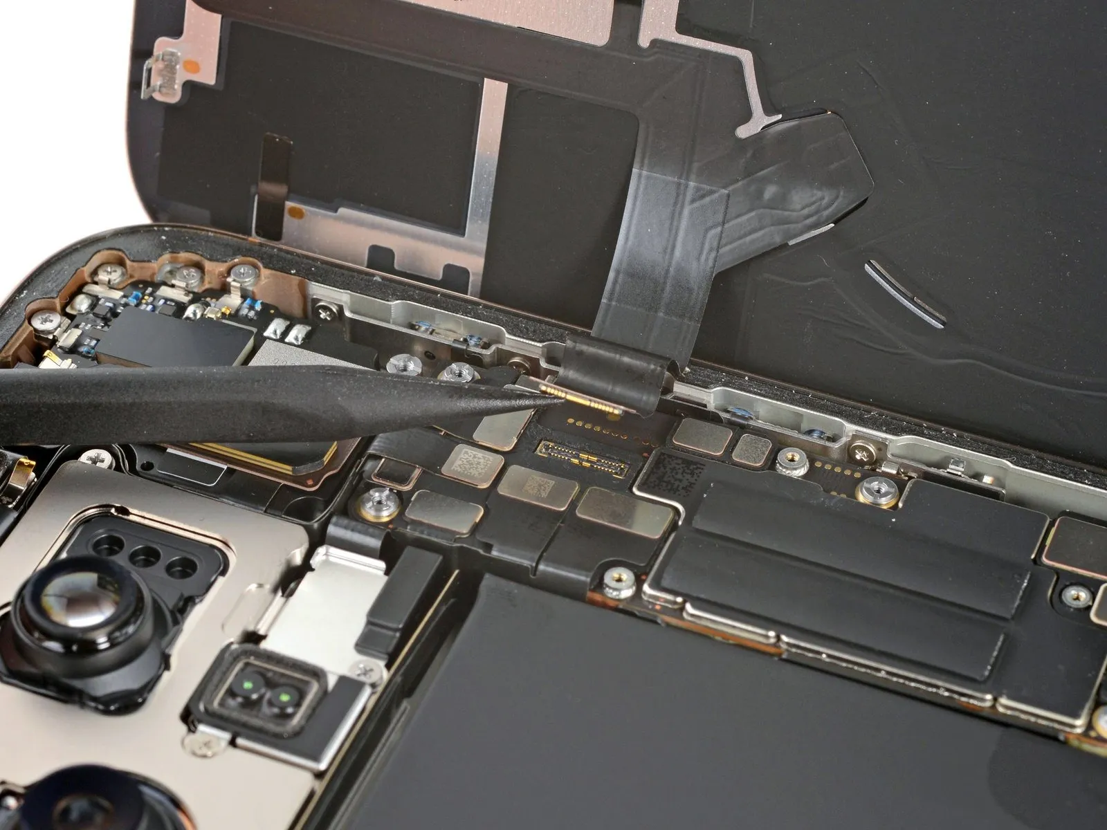
- Apply heat to the lower assembly's cable section, situated above the Taptic Engine, utilizing a hair dryer until the surface reaches a temperature that is perceptible upon contact.
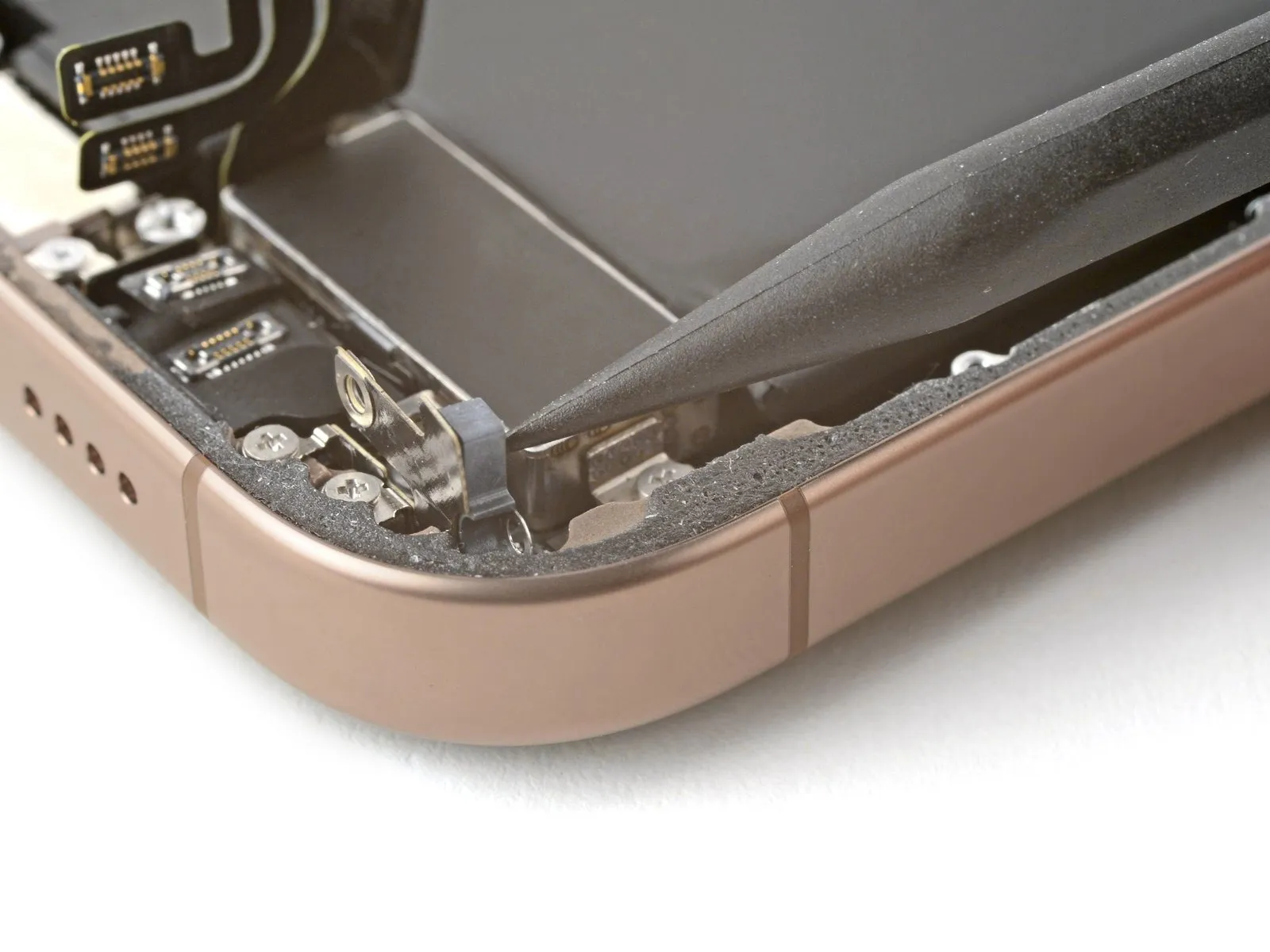
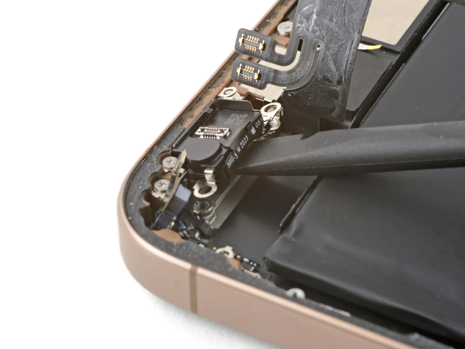
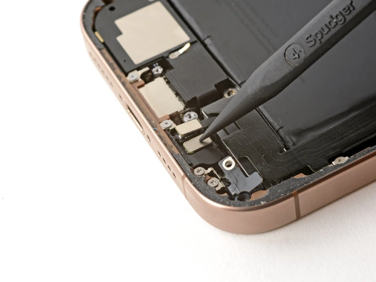
Step 29
- Insert an opening pick beneath the lower assembly cable to facilitate its detachment from the Taptic Engine.The Taptic Engine's connection to the lower assembly cable requires separation using an opening pick.To allow access to the Taptic Engine, gently maneuver the lower assembly cable away from its position.Bending the lower assembly cable provides the necessary clearance to work on the Taptic Engine.The Taptic Engine is located beneath the lower assembly cable, necessitating its movement.
- Employing an opening pick is essential for disengaging the lower assembly cable.Ensure the lower assembly cable is sufficiently displaced to permit manipulation of the Taptic Engine.Positioning the opening pick under the lower assembly cable initiates the disengagement process from the Taptic Engine.
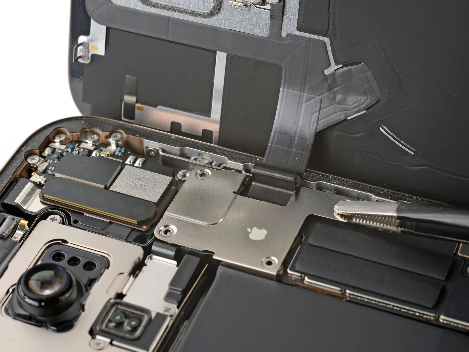
Step 30 | Remove the Taptic Engine
- Employ a Phillips screwdriver for the task of detaching the fastener.The screw, measuring 2.1 millimeters in length, requires a Phillips screwdriver for removal.A Phillips screwdriver is necessary to unscrew the small fastener.To release the Taptic Engine, a Phillips screwdriver is needed to extract the screw.The 2.1 mm screw must be removed using a Phillips screwdriver.Utilize a Phillips screwdriver to loosen and extract the screw that holds the Taptic Engine in place.A Phillips screwdriver is the appropriate tool for disengaging the 2.1 mm screw which secures the Taptic Engine.
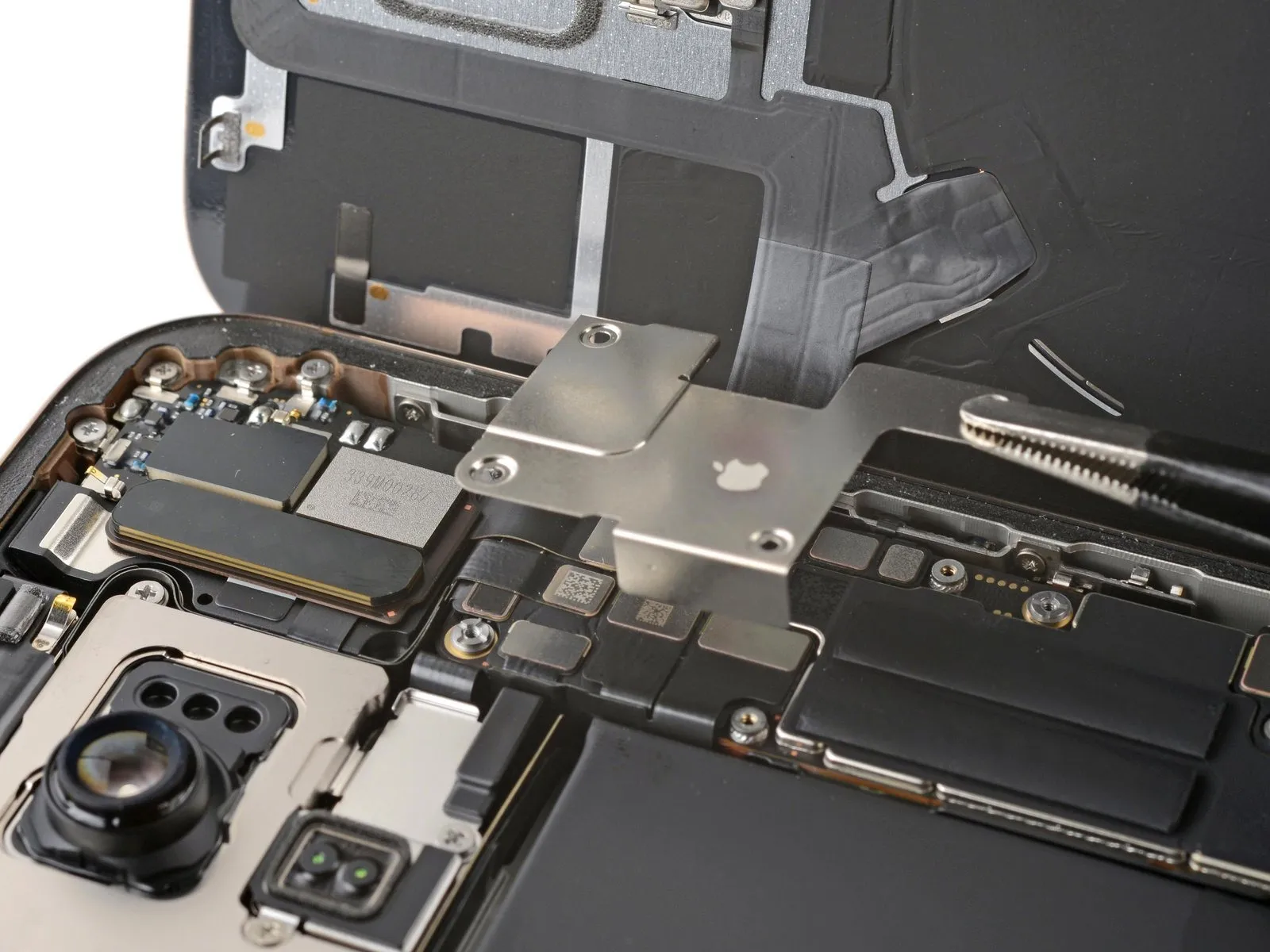
Step 31
- Employ the tip of a spudger to gently lift the corner bracket.A spudger's pointed end facilitates the upward movement of the corner bracket.To raise the corner bracket, utilize the pointed end of a spudger for leverage.
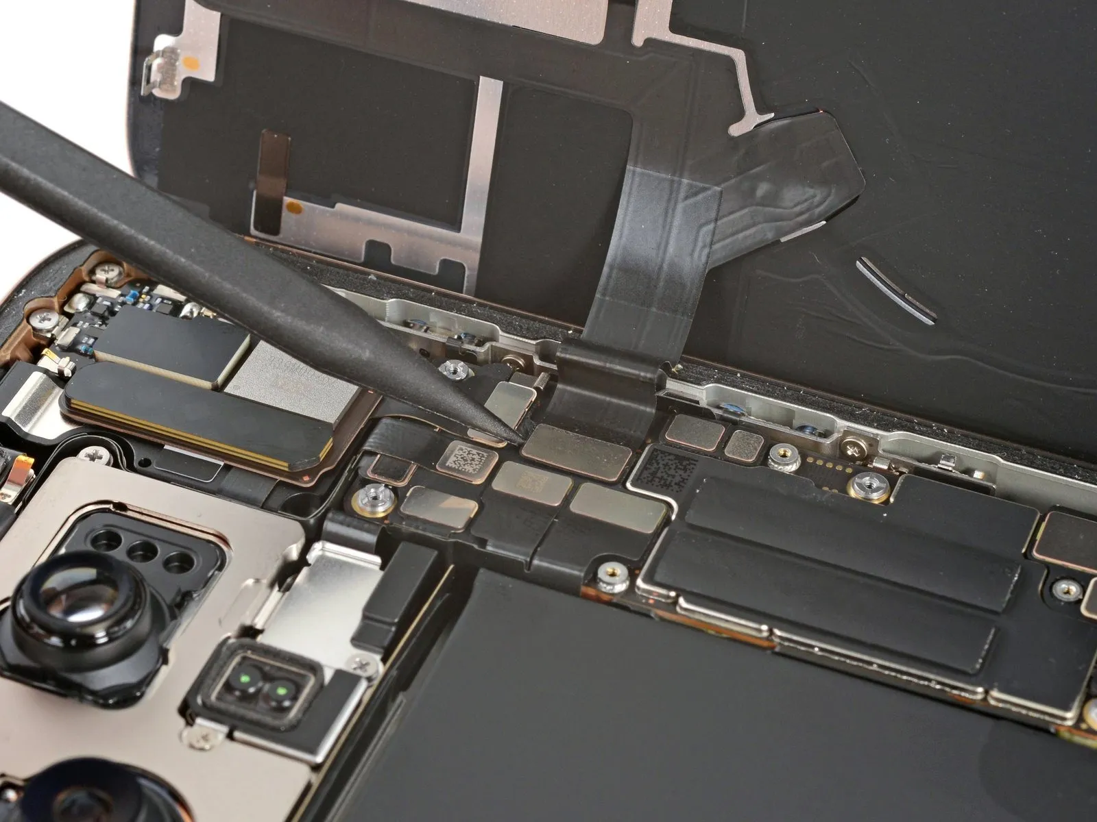
Step 32
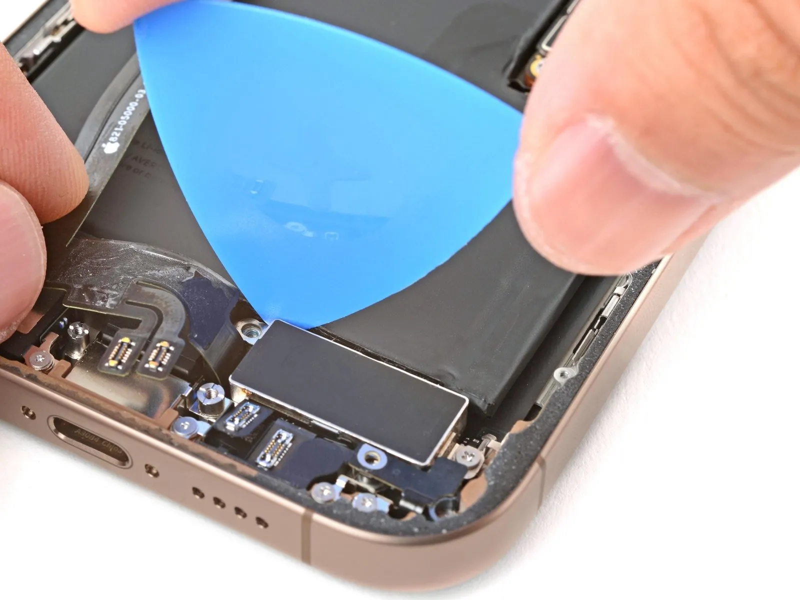

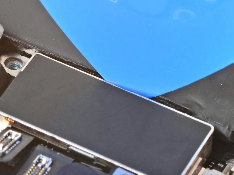
- Utilize the pointed end of an opening pick to gently disengage the Taptic Engine from its surrounding components.Position the opening pick's tip along the superior boundary of the Taptic Engine.The plastic buffer strip, which is affixed to the Taptic Engine, must be detached using this method.A sliding motion along the top edge facilitates separation of the buffer strip.This action effectively releases the adhesive bond between the plastic buffer strip and the Taptic Engine.
Step 33
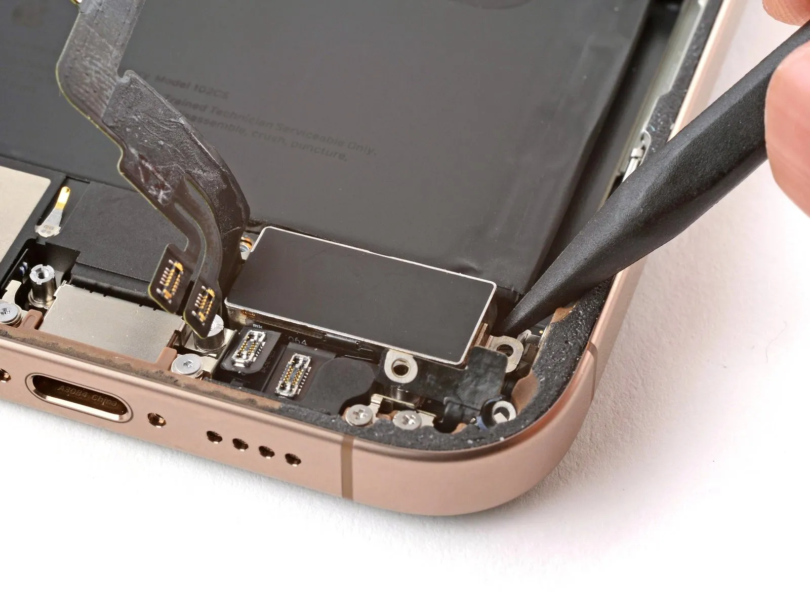
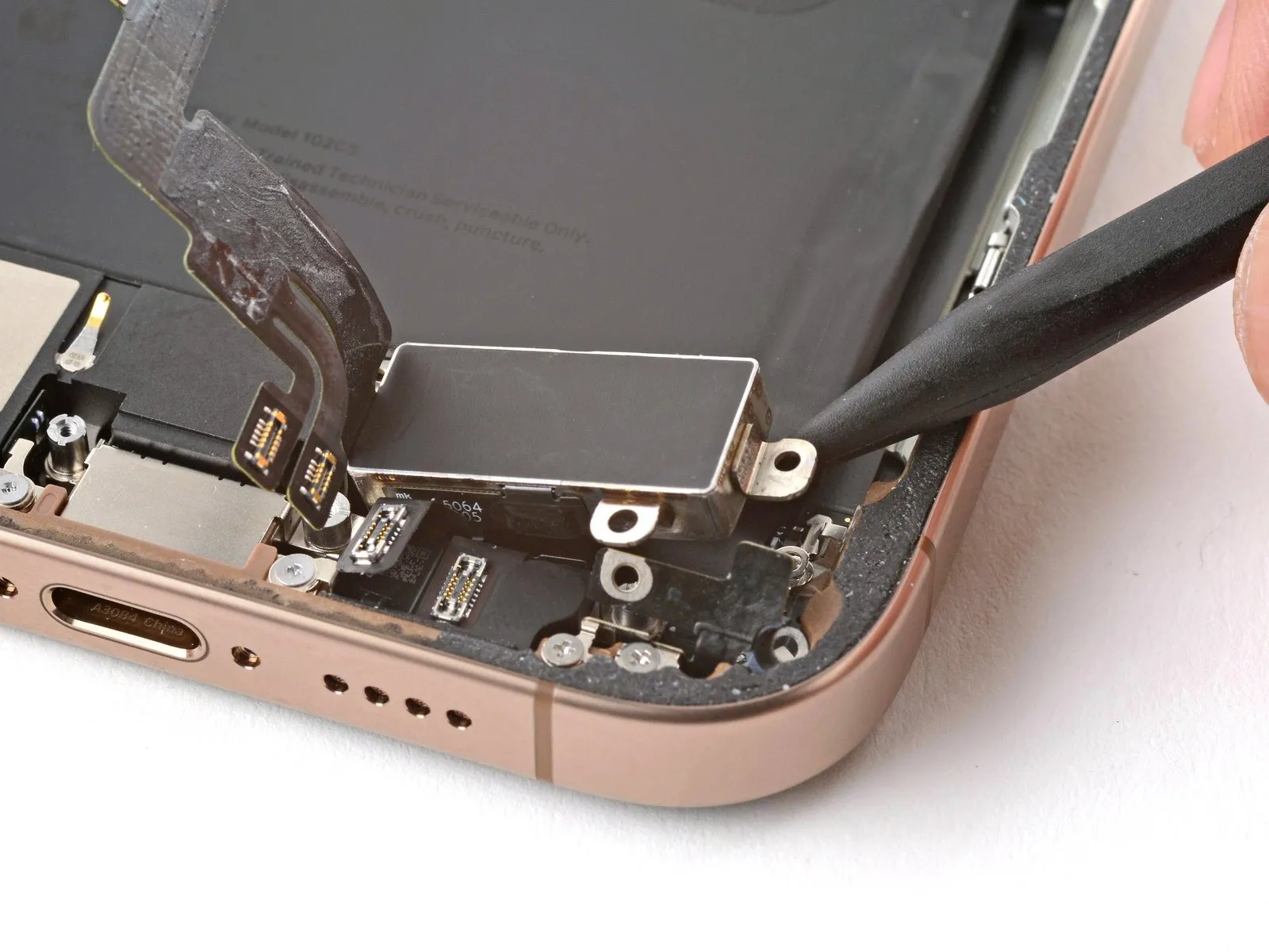
- Employ the tip of a spudger for gently lifting the Taptic Engine.Exercise caution to avoid applying pressure to the battery during the separation process.The Taptic Engine can be disengaged using a spudger's pointed end.Carefully detach the Taptic Engine, ensuring the battery remains undisturbed.Utilize the spudger's point to facilitate the Taptic Engine's release.
- Prevent contact between the spudger and the battery to avoid damage.The Taptic Engine’s removal requires a precise prying action with a spudger.To free the Taptic Engine, leverage the spudger's tip with controlled force.
- Avoid applying force to the battery while disengaging the Taptic Engine.A spudger’s pointed tip is the appropriate tool for separating the Taptic Engine.The Taptic Engine must be lifted using the spudger, taking care to protect the battery.
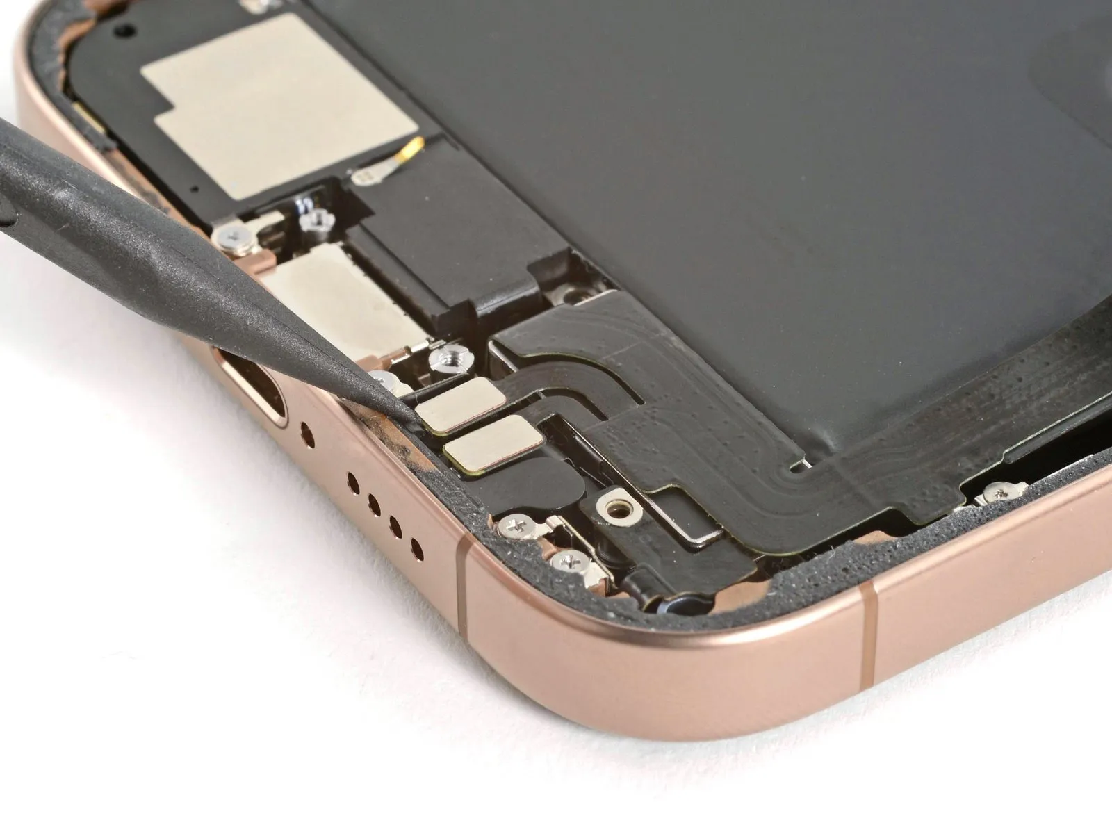
Step 34 | Remove the bottom microphone
- To detach the lower microphone assembly, first loosen the three screws that hold it in place.
- Utilize a single, 3.4-millimeter-length standoff screw for disassembly.Employ another standoff screw, measuring 3 millimeters in length, during the repair process.
- A third screw, characterized by a 1.4-millimeter length and a tri-point Y000 head, is also required.The three screws, each with distinct lengths, are critical for microphone retention.
- Carefully unscrew the fasteners to prevent damage to surrounding components.Ensure proper screw identification based on their specified dimensions and head type.
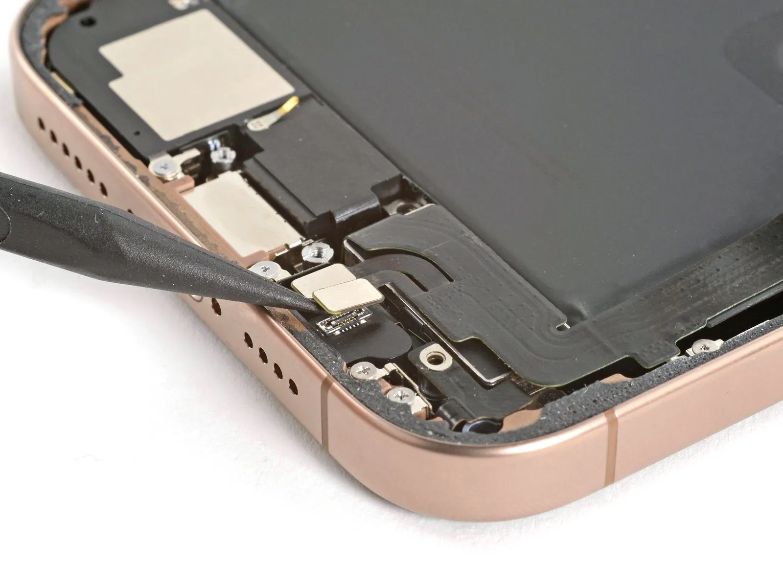
Step 35
- Employ the planar edge of a spudger tool to carefully disengage the lower microphone assembly.
Avoid applying force against the battery during this process, as damage could occur.Expect a degree of adhesion as the microphone separates from its sealing gasket.The microphone's securement will require a gentle, controlled release.
Complete the removal of the lower microphone component. - Ensure the microphone is fully detached from the device's housing.
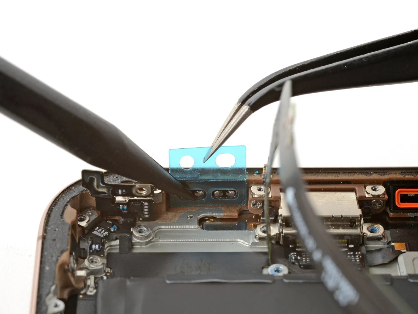
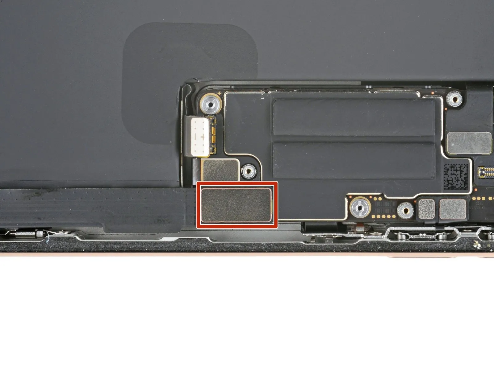
Step 36 | Remove the adhesive gasket

Employ tweezers or manual dexterity to detach the existing adhesive gasket.The component requiring removal is the adhesive gasket, situated on the frame's lower surface.Carefully extract the gasket, ensuring no residue remains on the frame's bottom.
Step 37 | Disassembly complete

Having finished the disassembly process, the subsequent instructions detail the reassembly procedure for your iPhone.
Slight variations in the appearance of reassembly images might occur based on the specific iPhone model being serviced, but the outlined steps remain accurate for all versions.
Step 38 | Install the bottom microphone

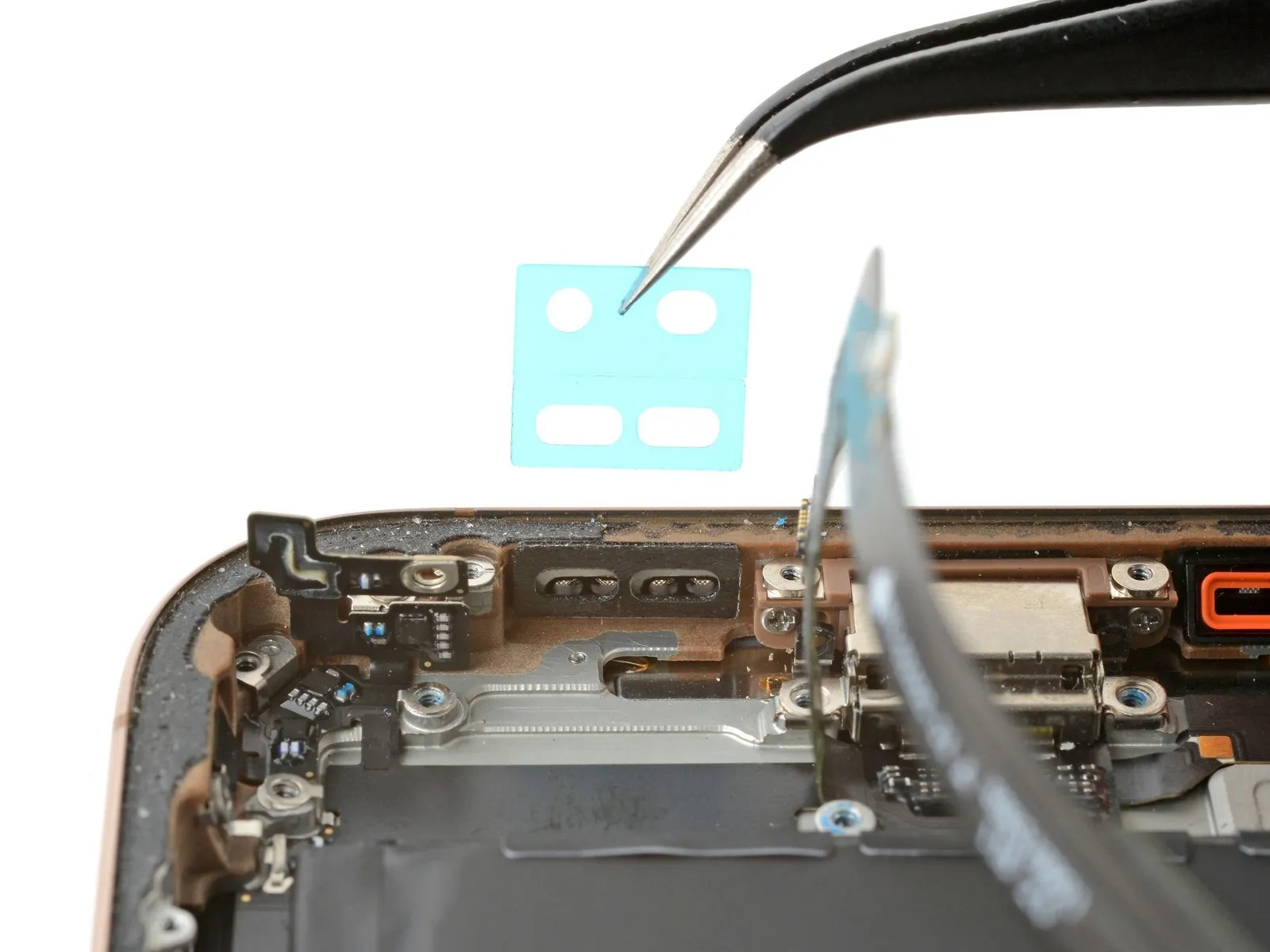
- Carefully separate the protective backing from the microphone adhesive gasket.
- Position the gasket precisely over the microphone opening in the frame, then secure it with gentle pressure applied via a spudger.
- Completely remove any remaining adhesive backing material.
Step 39
To ensure proper seating, position the microphone at a downward inclination and guide it into its designated cavity, subsequently applying even pressure to secure it flush against the device's housing.
Step 40
- To affix the lower microphone assembly, utilize the provided fasteners.
Employ a standoff screw measuring 3.4 millimeters in length for secure attachment.
A separate standoff screw, with a 3-millimeter length, is also required for this process.
The final fastening point necessitates a 1.4-millimeter tri-point Y000 screw.
Step 41 | Install the Taptic Engine
Position the Taptic Engine component within its designated cavity.Ensure the Taptic Engine is situated correctly inside the intended space.Place the Taptic Engine into the recessed area for proper installation.
Step 42

Employ a fingertip to rotate the corner bracket downwards to its designated position.
Step 43
Employ a Phillips screwdriver for the installation process.A 2.1 millimeter screw is required for this step.The screw's purpose is to fasten the Taptic Engine.Secure the Taptic Engine using the provided screw.Utilize a Phillips head screwdriver to perform the fastening.The Taptic Engine is held in place by a screw measuring 2.1 mm in length.To affix the Taptic Engine, a Phillips screwdriver and a 2.1 mm screw are necessary.
Step 44
Carefully position the lower assembly cable against the Taptic Engine's surface by applying gentle pressure with a fingertip.Ensure the cable makes firm contact with the Taptic Engine to guarantee proper connection.This action secures the lower assembly cable to the Taptic Engine.
Step 45
- To affix the lower assembly cable, utilize two screws, ensuring their proper placement and tightness.
A tri-point Y000 screw, measuring 1.0 millimeters in length, is required for this installation.
Additionally, a Phillips screw with a length of 1.3 millimeters must be incorporated.
Step 46
Step 47
- Position the Taptic Engine cover over the device, carefully matching the screw apertures for accurate placement.
Verify secure engagement of the cover's lower boundary with the chassis to guarantee a proper seal.
Step 48
- Employ a Phillips screwdriver for the attachment of the three screws that hold the Taptic Engine cover in place.
One screw measures 2.9 millimeters in length.
Another screw is 1.3 millimeters long.
The final screw has a length of 2.4 millimeters.
Step 49
Step 50 | Remove the leftover adhesive


- Exercise caution near the delicate grounding clips during frame cleaning, as damage can occur.
- Employ blunt-nose tweezers or your fingertips to detach sizable adhesive sections from the frame's edges.
- A spudger tool is necessary for the subsequent step.Employ a spudger to eliminate any remaining adhesive residue from the frame's surface.For adhesive that resists removal, localized heat application from a hair dryer or heat gun can facilitate the process.
- Should a grounding clip become displaced, restore its original position with careful manipulation using your fingers or tweezers.
Step 51 | Clean the back glass


Step 52 | Clean the frame

- To protect surfaces, cover the tip of a spudger with a clean, non-abrasive cloth or a coffee filter.Apply a small quantity of isopropyl alcohol with a concentration exceeding 90% to the cloth-covered spudger tip.Clean the adhesive remnants from the frame's edge by wiping in a single, consistent direction.Careful execution of this step is crucial.A thoroughly cleaned frame facilitates the even application of replacement adhesive.
- Consistent adhesive distribution is essential for achieving a strong and reliable bond.
- Proper surface preparation guarantees optimal adhesion during the reassembly process.
Step 53 | Apply the replacement adhesive

- To establish the correct positioning of the adhesive sheet, place it on the frame's surface.
- Employ elements like the camera aperture and the indentations situated on the superior and inferior borders to assess the adhesive's placement within the frame.
Step 54


- To reveal a portion of the adhesive, carefully lift the corner tab of the adhesive sheet's liner and remove it, exposing approximately one-third of the adhesive surface.Due to its high tack, the revealed adhesive possesses significant stickiness.Avoid any unintended contact with surfaces until the adhesive is prepared for application onto the frame.
- Should your adhesive contain several liners, remove the liner that exposes the side intended for bonding to the frame.
Step 55


- Ensure the visible perimeter of the adhesive strip is precisely matched to the matching edge found on the iPhone's structural frame.Because the adhesive will bond immediately upon contact, repositioning is impossible; any misalignment necessitates removal and replacement with a fresh adhesive strip.Confirming proper alignment is crucial before proceeding.
- Apply gentle, even pressure to secure the adhesive strip to the iPhone's frame.
Step 56


- Carefully detach the liner from the adhesive backing, applying even pressure to ensure proper contact.Accurate alignment of the adhesive is indicated by a seamless fit of the edges within the frame.To correct minor misalignments, delicately reposition the longer sides relative to the frame's boundaries.
- Should the adhesive develop creases or wrinkles, discard it and reapply a new set.
- In the absence of replacement adhesive strips, the iPhone can be reassembled and used temporarily, acknowledging a reduction in its water resistance.
- The iPhone's ability to repel water will be diminished until the adhesive is properly replaced.
Step 57


- Employ a spudger to apply pressure to the adhesive sealant that secures the iPhone's edges.Exercise caution to avoid damaging the delicate grounding clips during this process; should one become displaced, carefully reposition it using your fingers or tweezers.Excessive force should be avoided as it can distort the adhesive's original shape.
- The adhesive's integrity is maintained by applying even pressure across its circumference.
- Careful manipulation of the adhesive is necessary to prevent alterations to its structural properties.
Step 58


- Employ a spudger tool, or manually use your fingers, to detach the pull tab affixed to the extensive front liner.The pull tab's typical location is within a corner of the liner itself.Utilize the detached pull tab to carefully separate the large front liner from its adhesive backing.
- A remaining liner may still cover the outer edges, safeguarding the adhesive during reassembly; refrain from removing these smaller release liners at this stage.
- These smaller liners serve to prevent unintended adhesion during the iPhone's reassembly process.
Step 59 | Connect the back glass

To facilitate access, carefully support the rear glass component by applying pressure along its right-hand border.
Step 60

Employing either a fingertip or the planar edge of a spudger tool, establish a secure connection between the rear glass connector and the logic board by applying pressure.The back glass connector's physical interface with the logic board necessitates firm contact to ensure proper electrical function.Carefully align the connector before applying pressure to avoid damaging the delicate components on the logic board.
Step 61 | Connect the battery

- Initiate the iPhone's power sequence to confirm proper operation, then deactivate it to proceed with the remaining assembly steps.
- Should the iPhone fail to power on, establish a connection to a power source and attempt to activate it once more.
- In the event that a logic board replacement has been performed and the display remains unresponsive, consult the screen replacement guide for instructions on directly connecting the display connector.
- Ensure secure attachment of the battery press connector to the logic board by applying consistent pressure with either a finger or a specialized spudger tool.
Step 62 | Install the connector covers

Step 63
- The cover is secured with two screws, each measuring 1.3 millimeters in length.
- Additionally, two screws with a length of 1.0 millimeter are used for this attachment.
Step 64

Step 65
- These screws fasten the cover to the device.Proper use of the Y000 driver is essential to prevent damage to the screw heads.
- Ensure the screws are correctly aligned before applying torque.The battery connector cover's retention is dependent on the secure fastening of these three screws.
Step 66 | Remove the final adhesive liners


- Employing either your fingertips or a spudger, detach the surrounding adhesive protective layers to reveal the adhesive.
- During liner removal, prevent any contact between surfaces and the newly exposed adhesive material.
- Thoroughly inspect the device's frame and rear glass, eliminating any residual liners to ensure complete adhesive exposure.
Step 67 | Install the back glass


- Position the rear glass component onto the device frame, initiating the placement with the uppermost boundary.
- Should you encounter opposition during installation, a surrounding retaining clip might be deformed and compressed by the frame; carefully examine the area of resistance and delicately realign any clips exhibiting bends.
- Apply even pressure across the iPhone's borders to ensure the rear glass makes complete contact with the frame.
Step 68 | Apply heat to the perimeter

- Apply warmth to the outer edge of the rear glass utilizing a hair dryer, heat gun, or iOpener until the surface reaches a temperature just beyond comfortable touch.
- This thermal application reduces the adhesive's viscosity, facilitating a more secure subsequent bonding.
Step 69 | Apply pressure to the perimeter


Employ your fingertips to apply consistent, strong pressure encompassing the entire outer edge of the iPhone's casing.
Step 70


- Position the iPhone with its screen facing downwards onto a pristine, level workspace.
- Apply a continuous strip of adhesive tape along the outer edge of the rear glass to safeguard its cosmetic appearance.
- Arrange a circular stack of coins bordering the rear glass, constructing a barrier that matches the height of the rear camera lenses' projections.
- As an alternative method, secure the device with vise clamps along its edges to properly establish the fresh adhesive seal.
Step 71


- To apply even pressure, position four to five substantial volumes directly atop the iPhone's surface.
- Because the weight could potentially create minor marks on the book covers, avoid using materials of significant value.
- Allow the applied pressure to remain constant for approximately half an hour.
- This sustained force facilitates the bonding process of the adhesive material.
Step 72 | Install the pentalobe screws
Employ a P2 pentalobe driver for the installation process.The two screws, each measuring 7.4 mm in length, require this specialized tool.Securely fasten these screws to the device's structure, positioning them on both sides of the charging port.Proper application of the P2 pentalobe driver is essential for successful screw engagement.Ensure the screws are aligned correctly before tightening them to prevent damage.