iPhone 16 Pro Max Back Glass Replacement
This document provides instructions for substituting a damaged or fractured unit.The rear housing, sometimes referred to as the back cover or back glass, is the component in question.Within the iPhone 16 Pro Max.
- To proceed, ensure you have the necessary equipment: a Phillips head screwdriver, a 5.5mm wrench, and a torque wrench capable of applying 12 Nm, alongside the replacement thermal paste and the new fan assembly.Apply fresh adhesive specifically designed for back glass replacement, ensuring complete coverage around the perimeter and within the designated bonding areas as indicated in the service manual.Ensure all preceding steps are finalized to conclude the procedure.
Following the completion of the repair procedure, perform a calibration.Genuine Apple parts, sourced directly from the manufacturer, are used for this repair.Employ the Repair Assistant application to proceed.
Step 1 | Before you begin
- To mitigate safety risks associated with charged lithium-ion batteries, ensure your iPhone's battery level drops to less than 25% before proceeding.
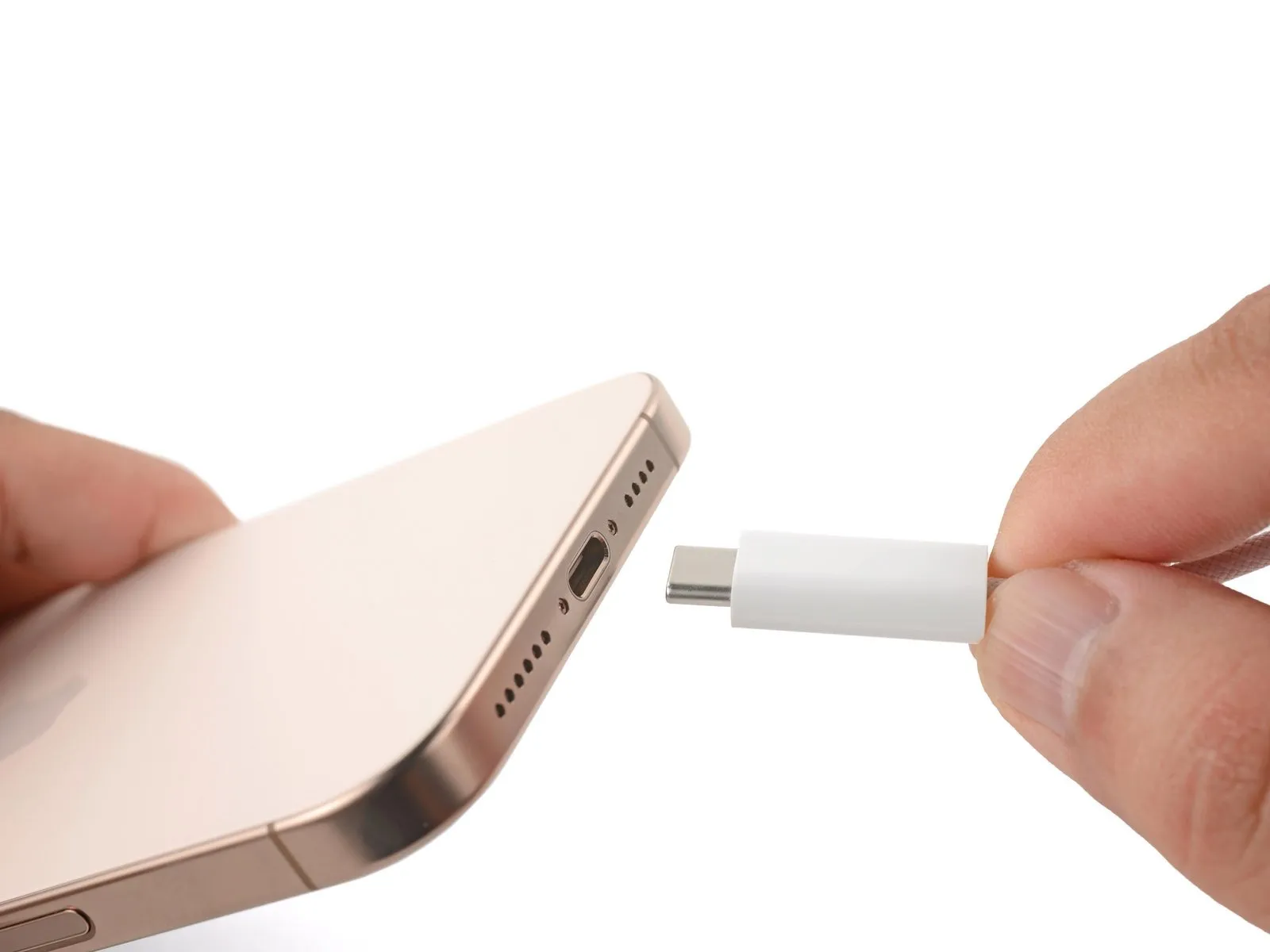
- Disconnect all connected cables from the iPhone.
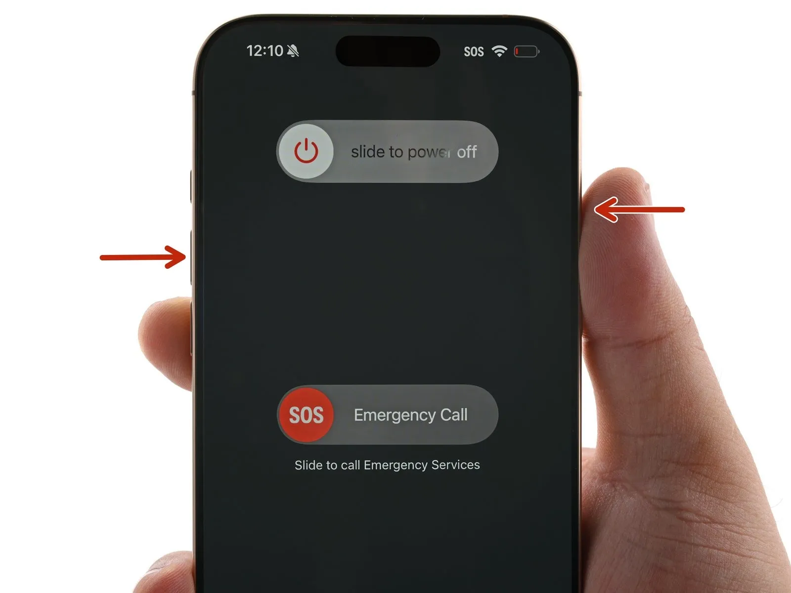
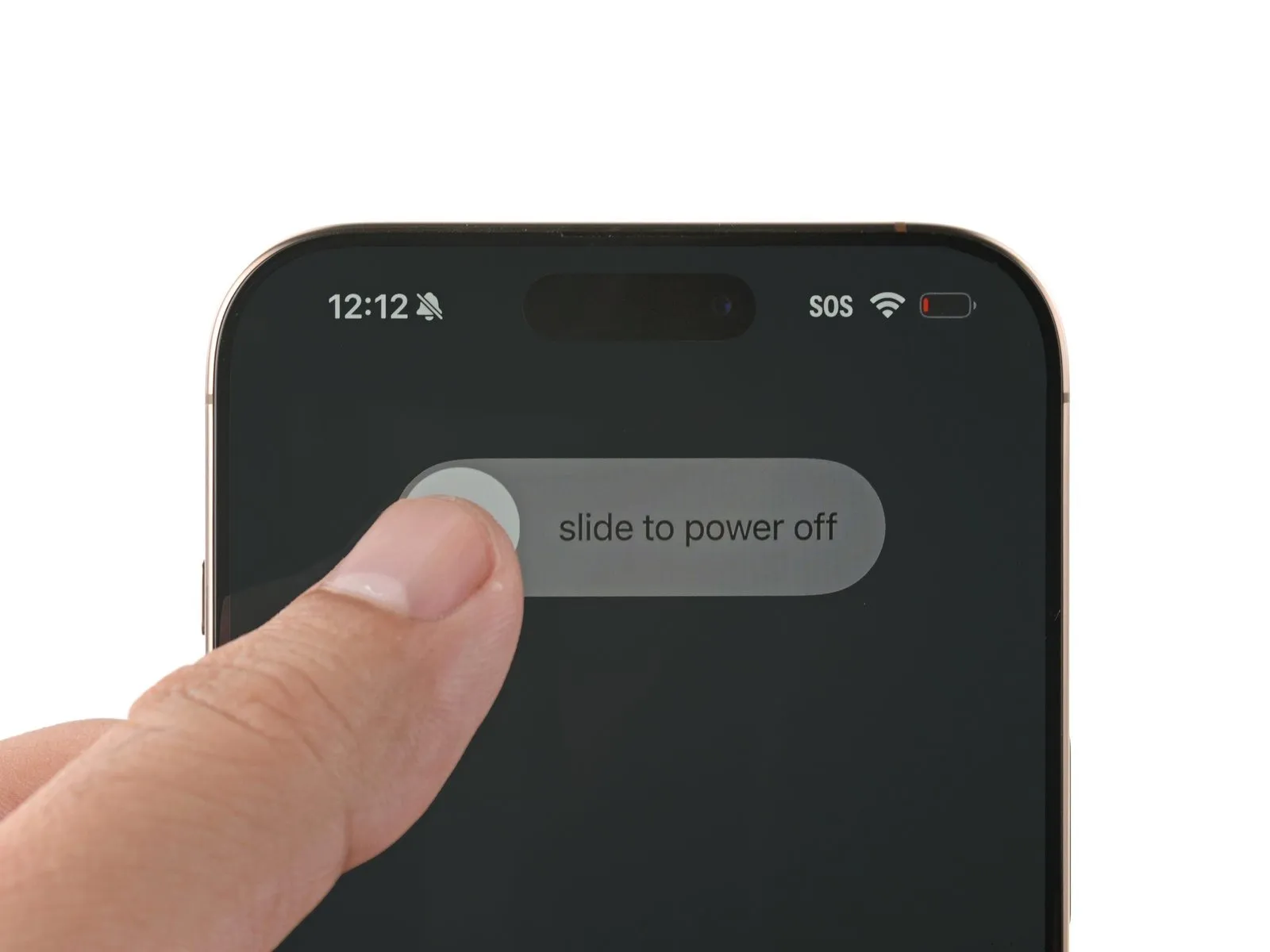
- Simultaneously press and maintain the power button while also pressing either volume button, then slide to shut down the iPhone.
Step 2 | Tape over any cracks
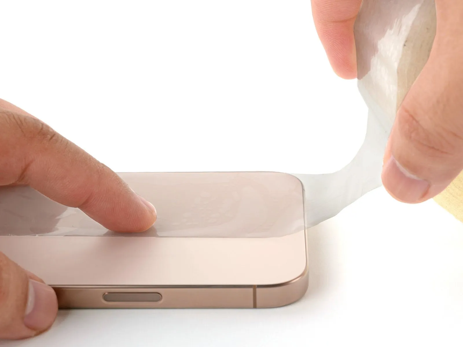
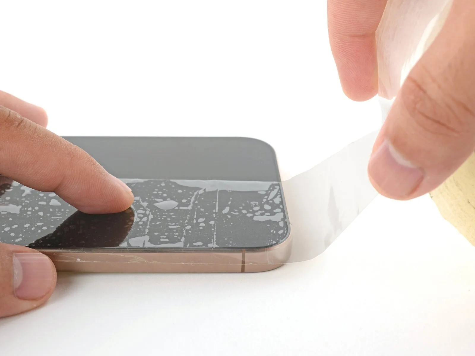
- To prevent injury and simplify the repair process when the display or rear glass exhibits severe cracking, apply strips of packing tape, ensuring they overlap, across the damaged surfaces.
- Ensure a flat surface, approximately the size needed to accommodate a suction cup, exists close to the lower perimeter.
Step 3 | Remove the pentalobe screws
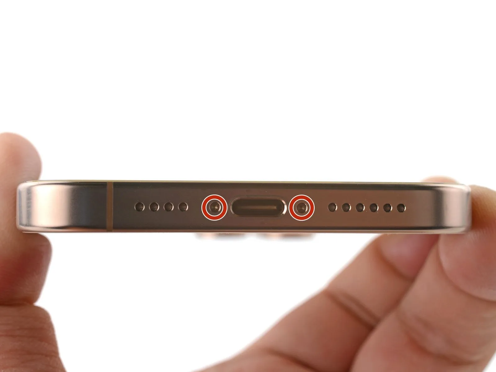

Employ a 3/8-inch socket wrench to tighten the fastener to a torque of 15 Nm, ensuring you observe all safety precautions and handle the component with care.Use a P2 driver with a pentalobe bit.Detach the pair of fasteners.Screws measuring 7.4 millimeters in length.Flanking the charging port are components on both the left and right sides.
Step 4 | Mark your opening picks


- Excessive insertion of the opening pick may result in device damage.
- To avoid potential damage, use a marker to clearly identify the pick.
- Determine the dimension using an appropriate measuring tool.Three millimeters.Using a permanent marker, indicate the opening point on the pick.
- Alternative corner markings, using the same measurement tools, can be applied to the remaining corners of the pick.
- Securely affix a coin to the tip of a pick using adhesive tape.Three millimeters.Beginning at the very end, proceed.
Step 5 | Create a gap using a suction handle
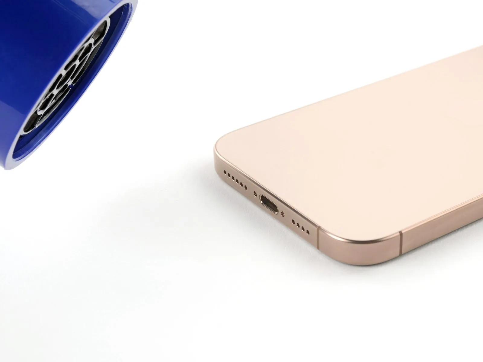
- Employ a suction handle to establish a starting space, as detailed in the following procedures.
- Employ a 3/8-inch socket wrench to tighten the fastener to a torque of 15 Nm, ensuring you observe all safety precautions and handle the component with care.Utilize a device designed to emit warm, directed airflow, typically employing a heating element and fan, to dry hair; ensure the appliance's wattage is appropriate for the intended application and observe all safety precautions outlined in the manufacturer's documentation.orApply warmth using a device that generates heat.Apply heat to the lower perimeter of the rear glass panel until its surface is warm enough to be comfortably touched.
- Alternatively, employ anUse the iOpener.Apply warmth to the rear glass assembly.
- To properly use the adhesive, adhere to these steps: warm the material and then apply it.Use a specialized device designed for electronics disassembly, such as an iOpener, to gently loosen adhesive bonds.Ensure the component is correctly positioned and secured, adhering to specified tolerances and manufacturer guidelines.
Step 6


- Using a suction handle, secure a grip on the lower edge of the rear glass panel.
- Apply firm, consistent upward pressure to the handle to separate the rear glass from the frame.
- Increase the temperature applied to the edge and repeat the process until a separation is visible.
- Carefully slide the pointed end of a prying tool into the separation.
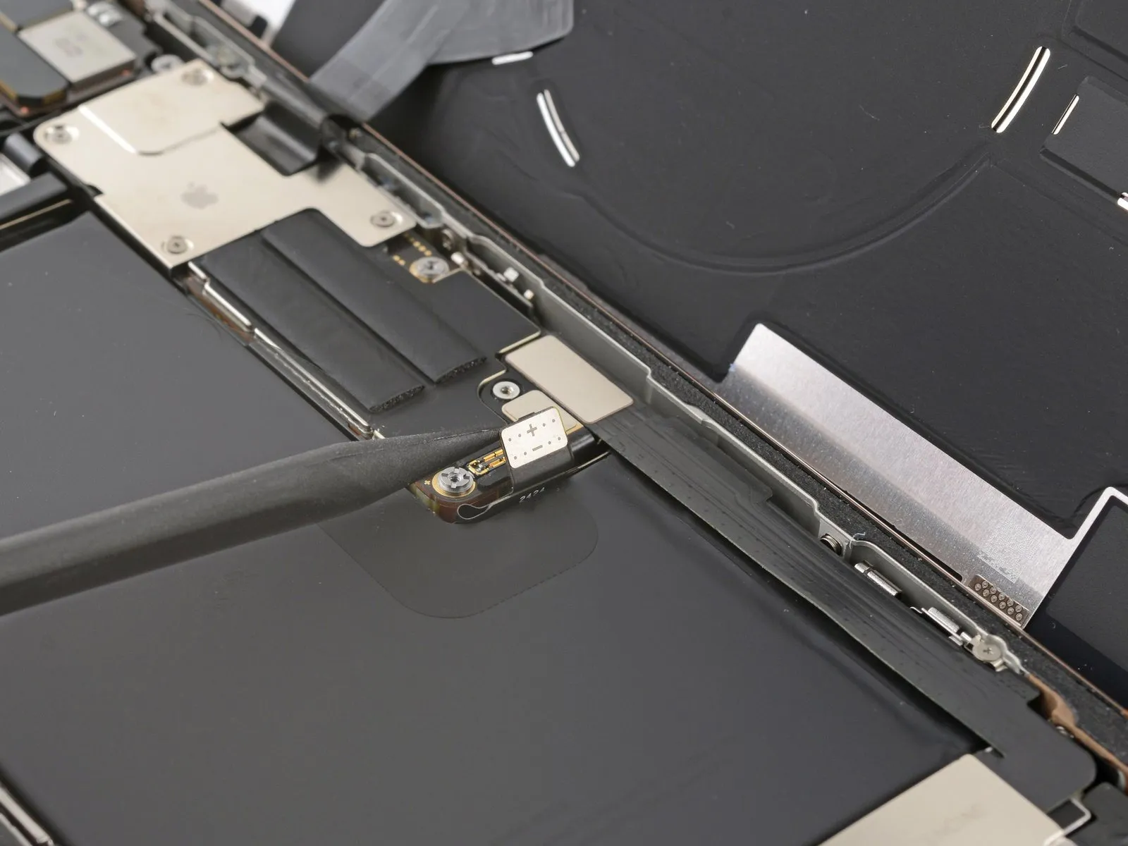
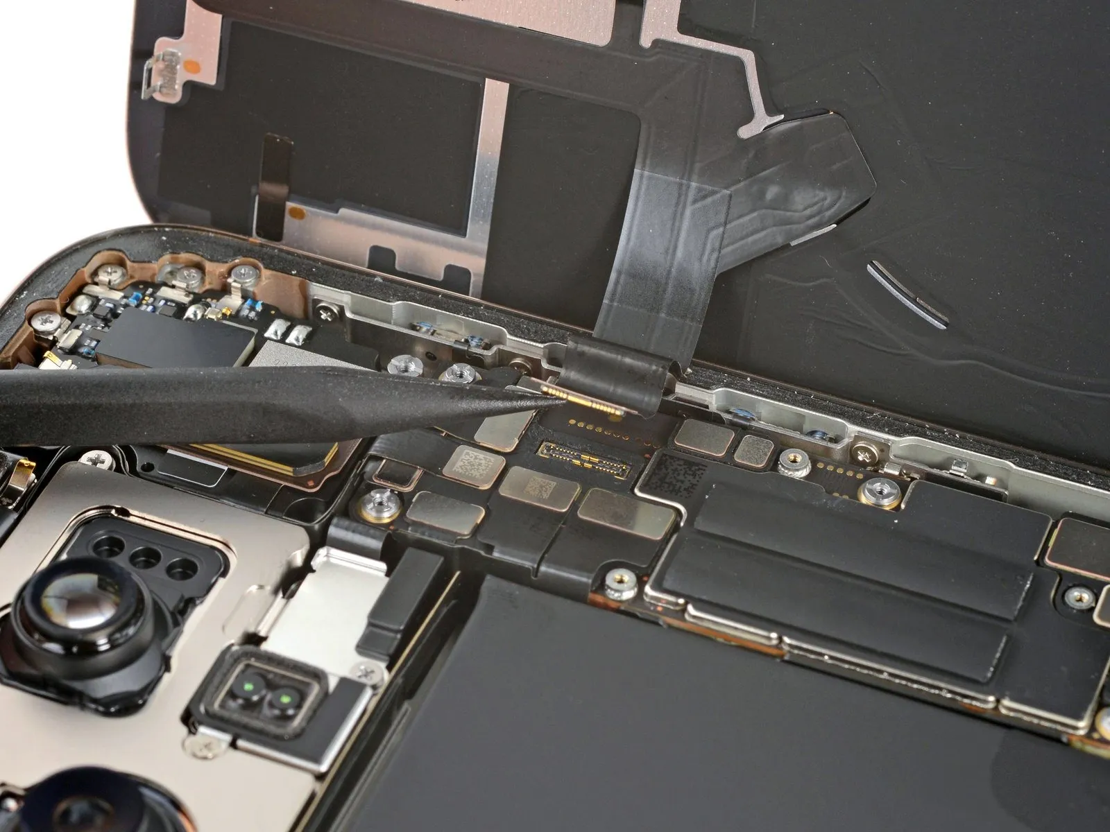
Step 7 | Back glass information
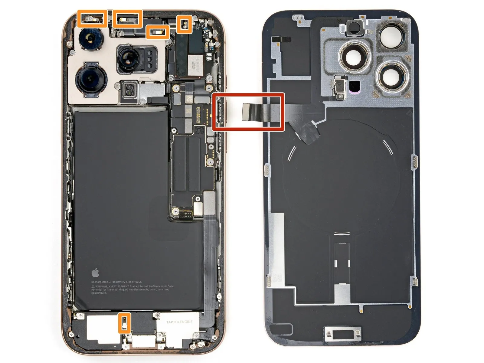
- During the subsequent steps when separating the back glass, ensure the tool remains shallow, never exceeding a depth of 3mm.Three millimeters.Exercise caution to prevent harm to these components.
- Carefully locate the thin, fragile cable situated near the volume up button, as it links the rear glass assembly to the iPhone; avoid inserting any tools into this area to prevent cable damage.
- The iPhone incorporates numerous spring-loaded electrical contacts arranged circumferentially.
Step 8 | Separate the bottom edge adhesive

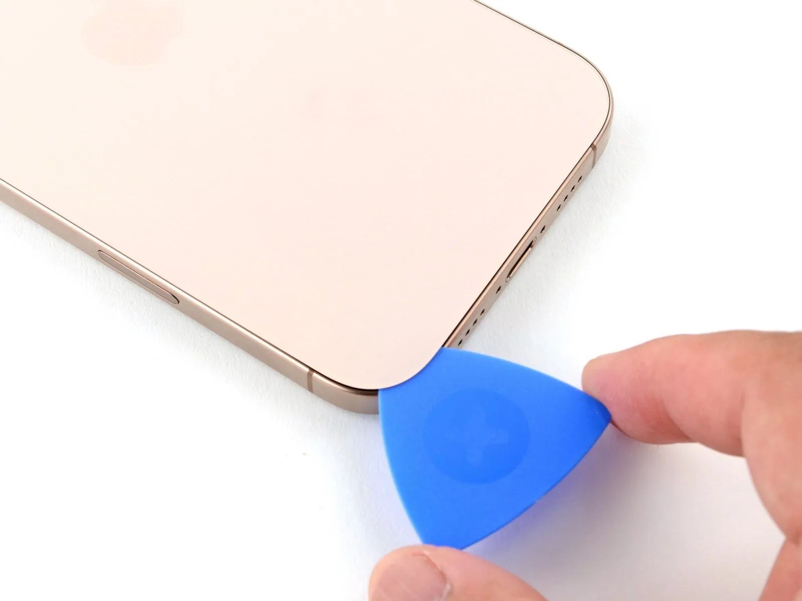
- Using a thin opening pick, carefully separate the adhesive bond by gently moving it along the lower perimeter.
- To ease cutting, apply heat to the adhesive edge for one minute and retry the slicing process.
- To avoid the adhesive bonding shut, maintain a separation tool in the lower left aperture.
Step 9 | Heat the left edge
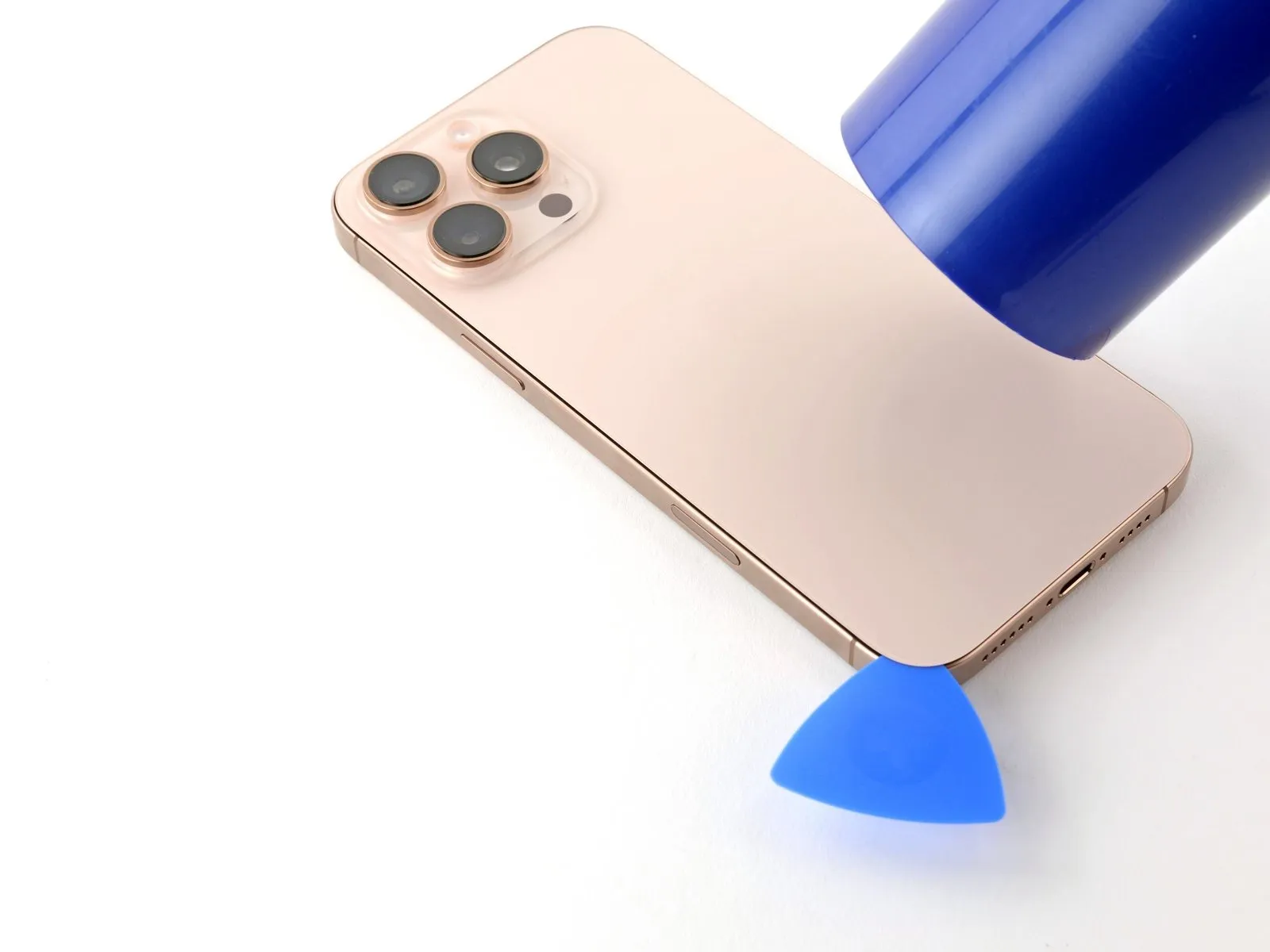
Apply warmth with a hair dryer or heat gun.Apply warmth, ensuring the temperature reaches the specified level.Apply heat to the left side of the rear glass panel until its surface temperature is high enough to be felt as hot when touched.
Step 10 | Separate the left adhesive

- Position another opening pick near the first, specifically in the lower-left corner.
- Avoid pushing the tool beyond the specified depth.Three millimeters.Exercise caution to prevent harm to the spring contacts.
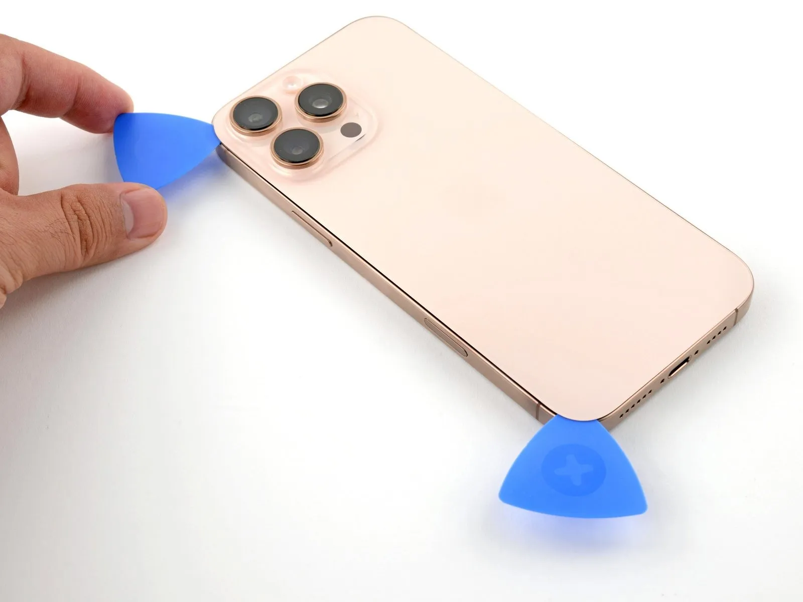
- Using a pick, carefully work along the left side, releasing the metal clips as you sever the adhesive bond.
- As the clips slide past, you will notice and sense them disengaging.
- To stop the adhesive from bonding during reassembly, maintain the presence of the pick in the upper-left corner.
Step 11 | Heat the top edge and corner

Apply warmth with a hair dryer or heat gun.Apply warmth, ensuring the temperature reaches the specified level.Apply heat evenly across the back glass's upper edge and the upper-right corner, ensuring these areas reach a temperature that is noticeably warm when touched.
Step 12 | Separate the top adhesive

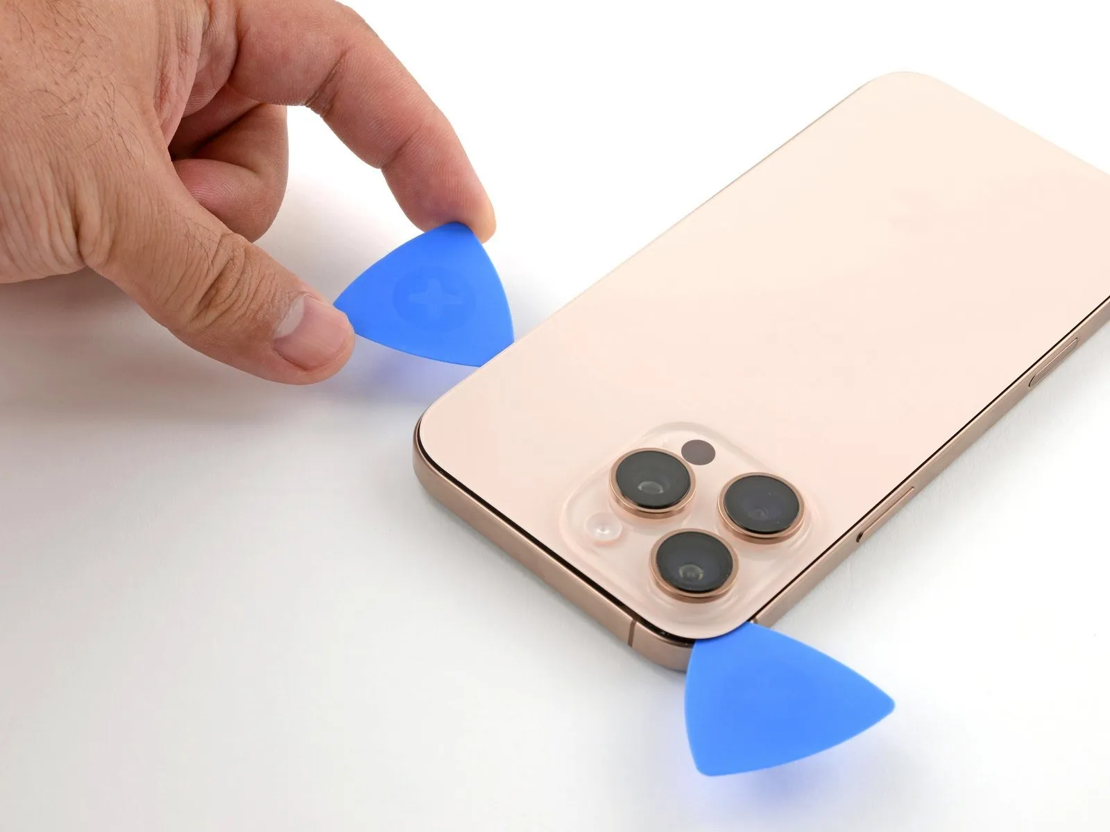
- Ensure the pick's insertion depth does not exceedThree millimeters.Exercise caution to prevent harm to the spring contacts.
- Position a third opening pick within the top-left corner.
- Using the opening pick, carefully maneuver it along the upper perimeter, progressing to the top-right corner and pausing directly over the volume up button.
- Maintain the pick's position within the gap to stop the adhesive from bonding again.
Step 13 | Heat the right edge

Step 14 | Separate the right adhesive


- Position a fourth opening pick at the lower-right corner.
- Position the opening pick along the device's corner, then move it upward along the right side, pausing just beneath the volume down button.
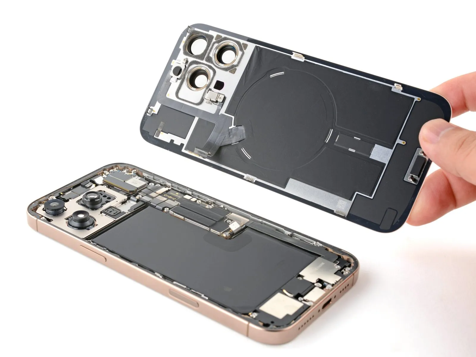
Step 15 | Reposition the back glass

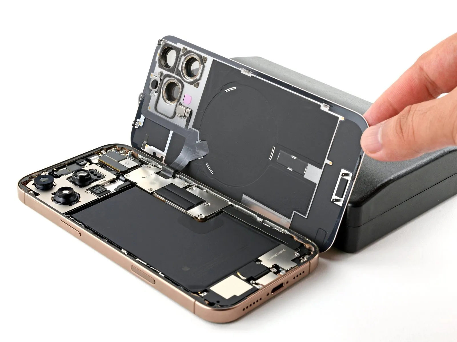
- Carefully pivot the rear glass assembly away from the iPhone body on its right side to release the remaining adhesive bond.
Step 16 | Remove the battery connector cover

- Use screws, each measuring 1.3 millimeters in length.
- A screw, measuring 1.0 millimeters in length, is required.
Step 17

Step 18 | Disconnect the battery
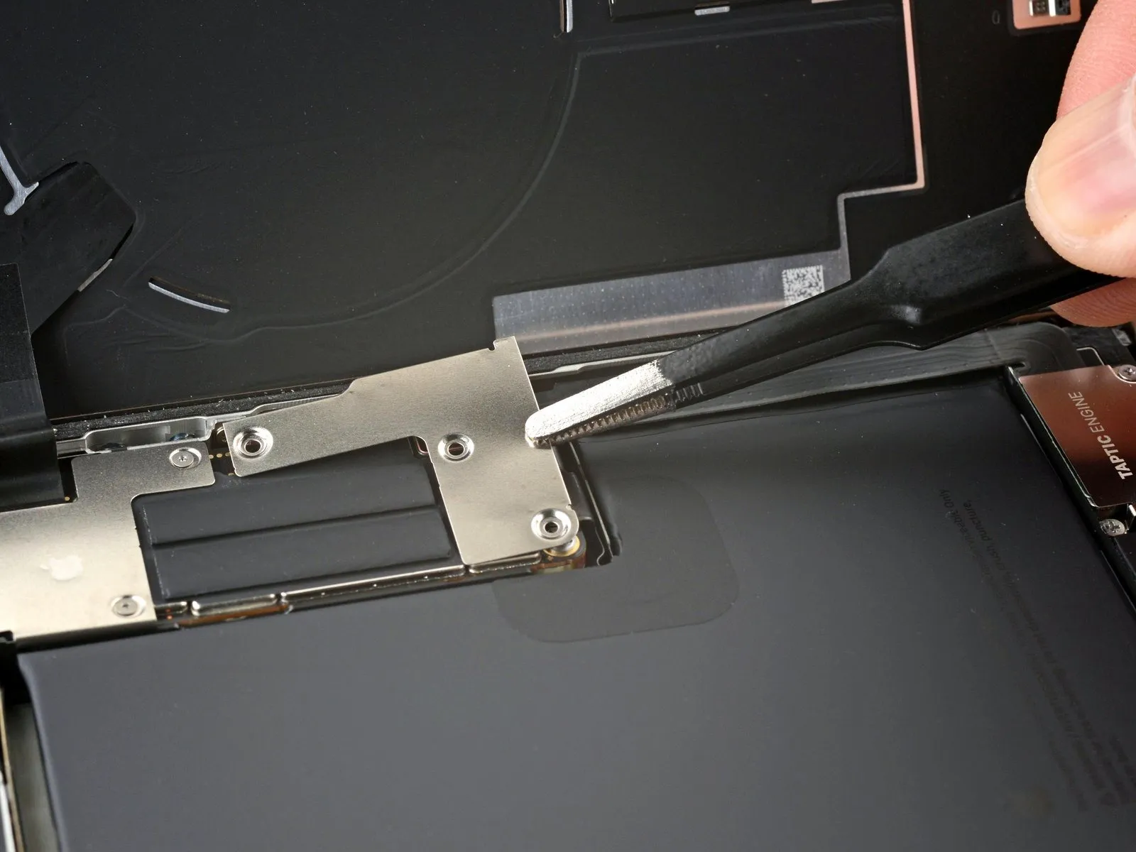
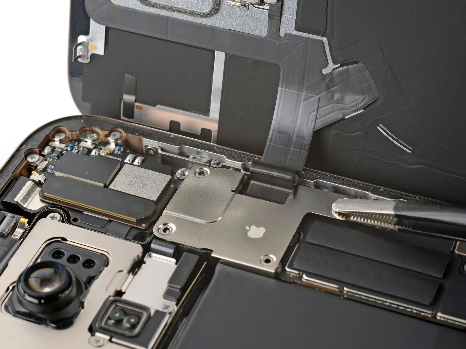
Step 19 | Remove the back glass connector cover

- Two.One point three millimeters.Utilize screws with a length of "long."
- Two.One millimeter.Utilize screws with a long shank.
Step 20
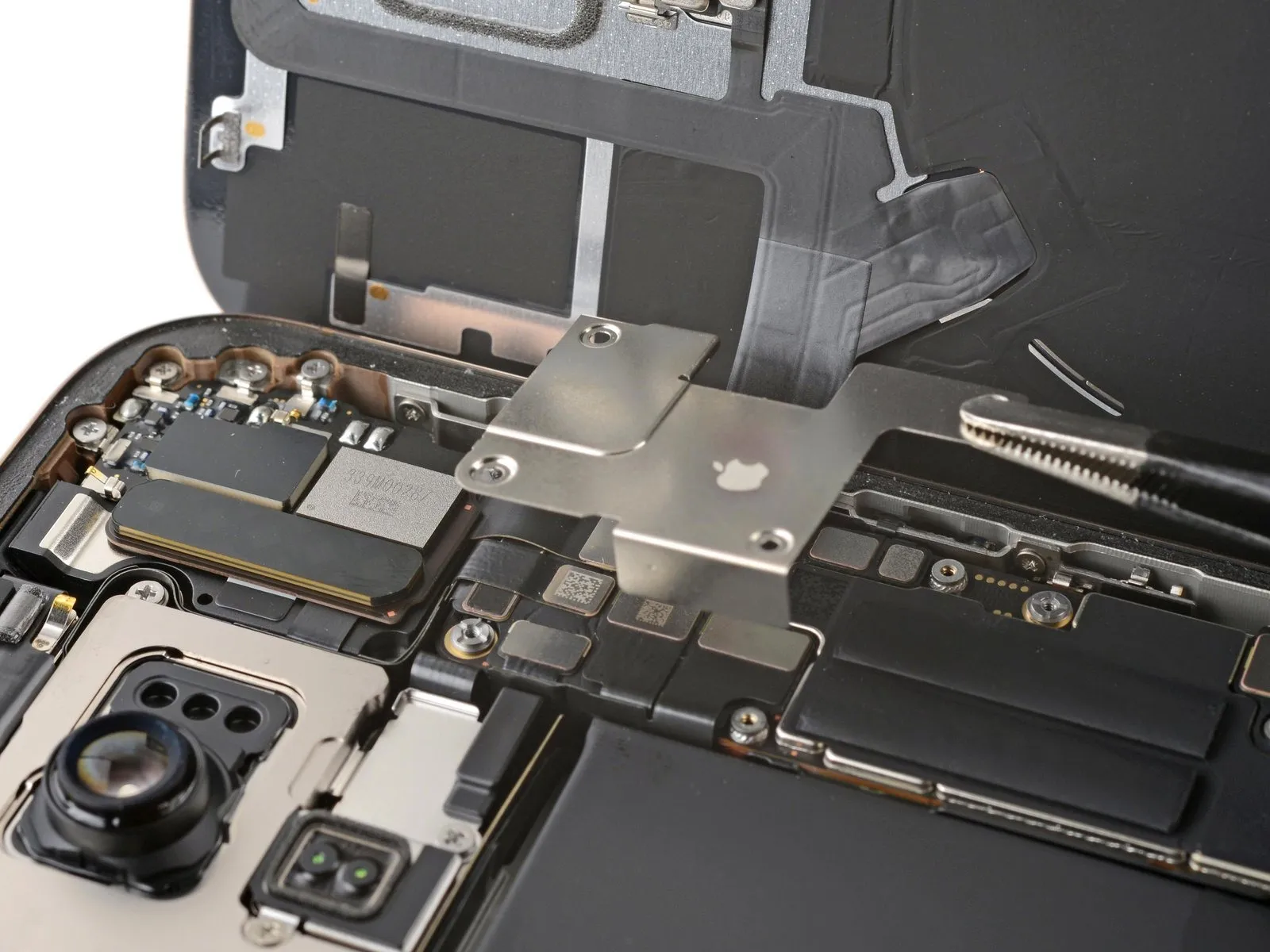
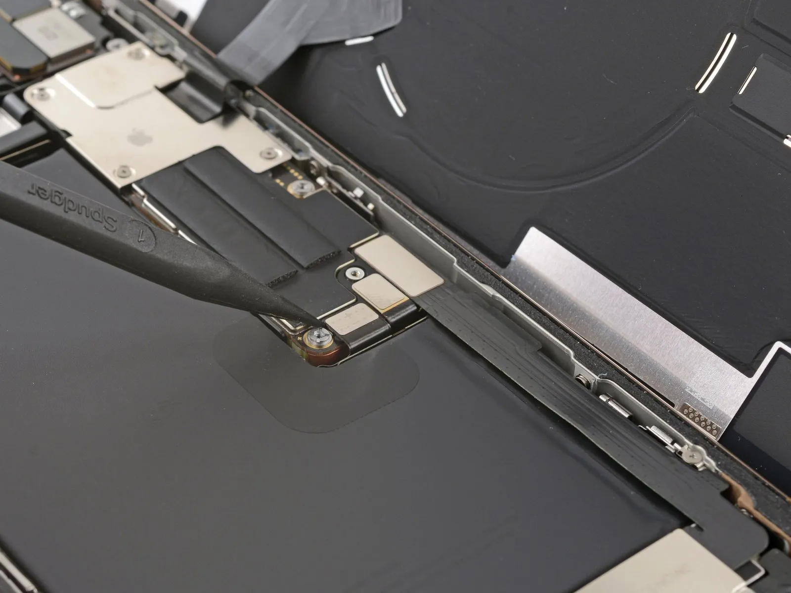
Step 21 | Remove the back glass
Carefully employ the tip of a screwdriver to apply pressure.Use a plastic pry tool, often referred to as a spudger, to carefully separate components.Carefully use a prying tool to release and detach the back glass connector.
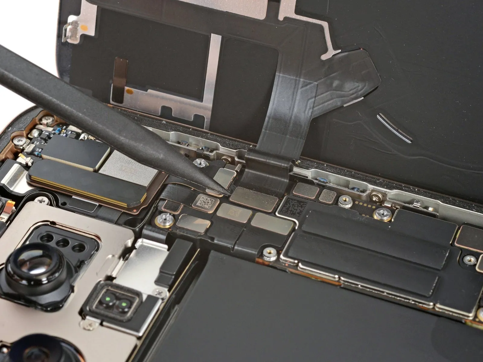
Step 22
Carefully detach the rear glass panel, ensuring no damage to surrounding components.
Step 23 | Disassembly complete

With the device now disassembled, proceed to the following instructions to reassemble your iPhone.
Visual differences in the assembly illustrations might occur based on your iPhone's specific version, but the steps remain accurate for all models.
Step 24 | Remove the leftover adhesive


- Exercise caution while cleaning the frame to avoid damaging the delicate grounding clips; should a clip become displaced, carefully restore it to its original position using your fingers or tweezers.
- Carefully detach substantial adhesive remnants from the frame's edges, employing either blunt-nosed tweezers or direct manual manipulation.
- Employ a 3/8-inch socket wrench to tighten the fastener to a torque of 15 Nm, ensuring you observe all safety precautions and handle the component with care.Use a spudger.Carefully remove any remaining adhesive from the frame's surface using a scraper.
- To loosen a firmly bonded adhesive, direct warm air from a hair dryer or heat gun onto the area and reattempt separation.
Step 25 | Clean the back glass


Step 26 | Clean the frame

- Using a spudger, carefully apply a small amount of highly-concentrated isopropyl alcohol to the area by covering the spudger's tip with a lint-free cloth or a coffee filter.Exceeding 90% is acceptable.Secure the component using a 3mm Allen wrench, ensuring a torque of 1.2 Nm to prevent damage.
- Using a cloth, remove adhesive residue by wiping consistently along the frame's edges.
- Careful execution is essential; a thoroughly cleaned frame surface promotes uniform adhesive distribution, which is critical for optimal bonding.
Step 27 | Apply the replacement adhesive

- Position the adhesive sheet onto the frame to confirm correct alignment.
- Carefully observe the frame's design elements—including the camera opening and indentations at the upper and lower borders—to anticipate the adhesive's placement.
Step 28


- Carefully lift the corner tab of the adhesive sheet and remove the liner, revealing approximately one-third of the adhesive surface.
- Because the adhesive surface is highly adhesive, prevent contact with other materials until you intend to bond it to the frame.
- Remove the protective layers from the adhesive until the surface designed to bond with the frame is revealed.
Step 29


- Ensure the adhesive strip's visible border is precisely matched to the iPhone frame's matching edge.
- Because the adhesive bonds immediately upon contact, any adjustments after initial placement are impossible; instead, the adhesive must be completely removed and replaced with a fresh application.
- Ensure proper positioning, then apply even pressure to secure the adhesive strip to the frame.
Step 30


- Carefully remove the backing liner while applying even pressure to secure the adhesive.
- Proper adhesive placement ensures the borders seat flush and without gaps.
- Carefully reposition any minor adhesive deviations by easing the extended borders toward the frame.
- Should the adhesive exhibit creases or wrinkles during application, discard the affected material and reapply using a new portion of adhesive.
- Should a replacement set of adhesive strips be unavailable, the iPhone can be reassembled and operated without them; however, be aware that the device’s water resistance will be reduced until the adhesive is properly replaced.
Step 31


- Carefully apply pressure along the device's edges with a spudger to release the adhesive securing it.
- Handle the delicate grounding clips with caution; if displacement occurs, restore them to their original position using your fingers or tweezers.
- Apply gentle pressure to avoid distorting or overextending the adhesive material.
Step 32


- Locate the large front liner, typically found in a corner, and gently detach it from the device using a spudger or by hand, carefully lifting the attached pull tab.
- Carefully separate the substantial adhesive front liner from its backing by grasping and lifting the designated pull tab.
- To avoid unintended adhesion during reassembly, a protective liner might still be in place around the edges; postpone its removal for now.
Step 33 | Connect the back glass

Step 34

Step 35 | Connect the battery

- Carefully engage the battery press connector with the logic board, applying pressure with a finger or spudger.
- Before completely closing the iPhone enclosure, verify the repair's functionality by powering on the device and confirming expected operation; then, turn it off again to proceed with reassembly.
- Attempt to power on the iPhone; if unsuccessful, establish a connection to a power source and repeat the power-on procedure.
- After logic board replacement, a non-functional display necessitates a manual connection of the display connector, as detailed in the screen guide.
Step 36 | Install the connector covers

Step 37
- Employ a Y000 tri-point screwdriver.Using the Phillips head screwdriver, fasten the four screws—each measuring 3.5mm—that hold the back glass connector cover in place.
Use screws, each measuring 1.3 millimeters in length.
Utilize screws, each measuring 1.0 mm in length.
Step 38

Position the battery connector cover so that the screw holes match up, then set it down.
Step 39
- Employ a Y000-sized tri-point screwdriver.Using a Phillips head screwdriver, fasten the battery connector cover in place with the three screws provided.
Use screws, each measuring 1.3 millimeters in length.
A screw, measuring 1.0 millimeters in length, is required.
Step 40 | Remove the final adhesive liners


Employ either your fingertips or a spudger.Carefully remove the complete border of liners, revealing the underlying adhesive.
To prevent adhesive contamination, avoid contact with any exposed surfaces during liner removal.
Carefully inspect the frame and rear glass, ensuring all stray liners have been eliminated; confirm their complete absence.
Step 41 | Install the back glass


- Align the upper edge of the back glass with the frame and gently position the entire component.
A sensation of obstruction indicates that the component is not moving freely and requires further inspection.Secure the component using the retaining clip.The clip might be deformed and compressed against the frame; identify the area where it's binding and carefully restore its shape.
Apply even pressure to all sides of the rear glass to ensure it makes complete contact with the device's frame.
Step 42 | Apply heat to the perimeter

- Apply warmth around the edges of the rear glass panel using a hair dryer, heat gun, or iOpener, ensuring the surface reaches a temperature just beyond comfortable touch.
Please provide the original text you want me to rewrite. I need the sentence or instruction to work with.Apply warmth, ensuring the temperature reaches a maximum of 150 degrees Fahrenheit, using a heat gun or hairdryer.The solvent reduces adhesive strength, facilitating improved adhesion.
Step 43 | Apply pressure to the perimeter


- Apply consistent, even pressure with your hands to encompass the entire outer edge of the iPhone.
Step 44


- Position the iPhone, with the display facing downward, on a clean, level workspace.
To shield the back glass's surface from scratches, apply a length of tape completely around its edges.
Position the component in a vertical arrangement.Metallic currency, including but not limited to denominations of various sizes and compositions, is required.Apply a continuous bead of adhesive along the entire edge of the rear glass, building up a raised border that matches the height of the rear camera lenses.
To ensure proper adhesion, secure the device's edges with vise clamps.
Step 45


- Position the component, ensuring alignment with the designated markings and within the specified 1.5mm tolerance, utilizing a precision screwdriver and observing the caution regarding static discharge.Apply downward pressure equivalent to the weight of three to four standard-sized, hardcover books.Position the device directly atop the iPhone, ensuring a flat and even alignment.
To avoid marking the lower book cover, use a substitute material instead of valuable items, as the coins’ weight could create a minor indentation.
Allow the books to remain positioned atop the device for approximately half an hour.
Applying force will engage the adhesive properties.
Step 46 | Install the pentalobe screws