iPhone 16 Pro Screen Replacement
This detailed procedure outlines the process for substituting a damaged display exhibiting cracks or failure to respond on an iPhone 16 Pro.To ensure a secure and proper seal, applying fresh replacement screen adhesive is essential for concluding this repair.A critical precaution is warranted:
Because the battery cannot be disconnected as part of this procedure, exercise extreme caution to avoid using metal implements or making contact with any exposed electrical connections within the iPhone.
- The potential for short circuits and further damage exists if metal tools are used or contacts are inadvertently touched.Following the screen replacement, it is necessary to perform a calibration of an authentic Apple display utilizing the Repair Assistant application.This calibration step is vital for optimal display functionality.The Repair Assistant application facilitates the precise adjustment of display parameters.
Failure to calibrate the screen may result in suboptimal performance or inaccurate color representation.
Step 1 | Prepare the phone for disassembly


- To optimize battery health, permit the phone's power source to deplete to a level below 25 percent capacity.A lithium-ion battery that has been charged presents a possible safety risk.
- Disconnect all connected wires and cords from the device.
- Simultaneously depress the power button and one of the volume buttons, then utilize the sliding mechanism to shut down the phone.
Step 2 | Tape over any cracks
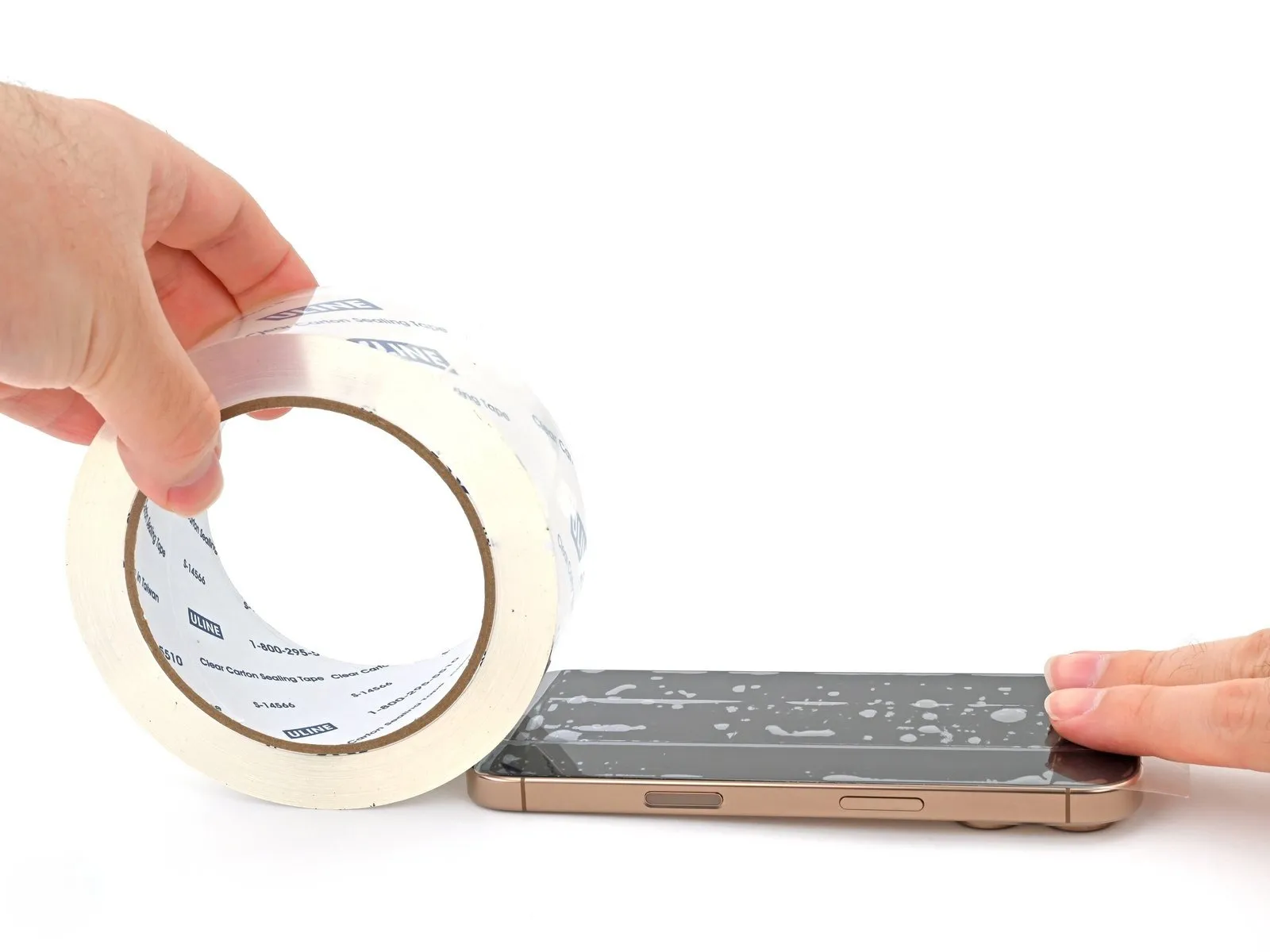
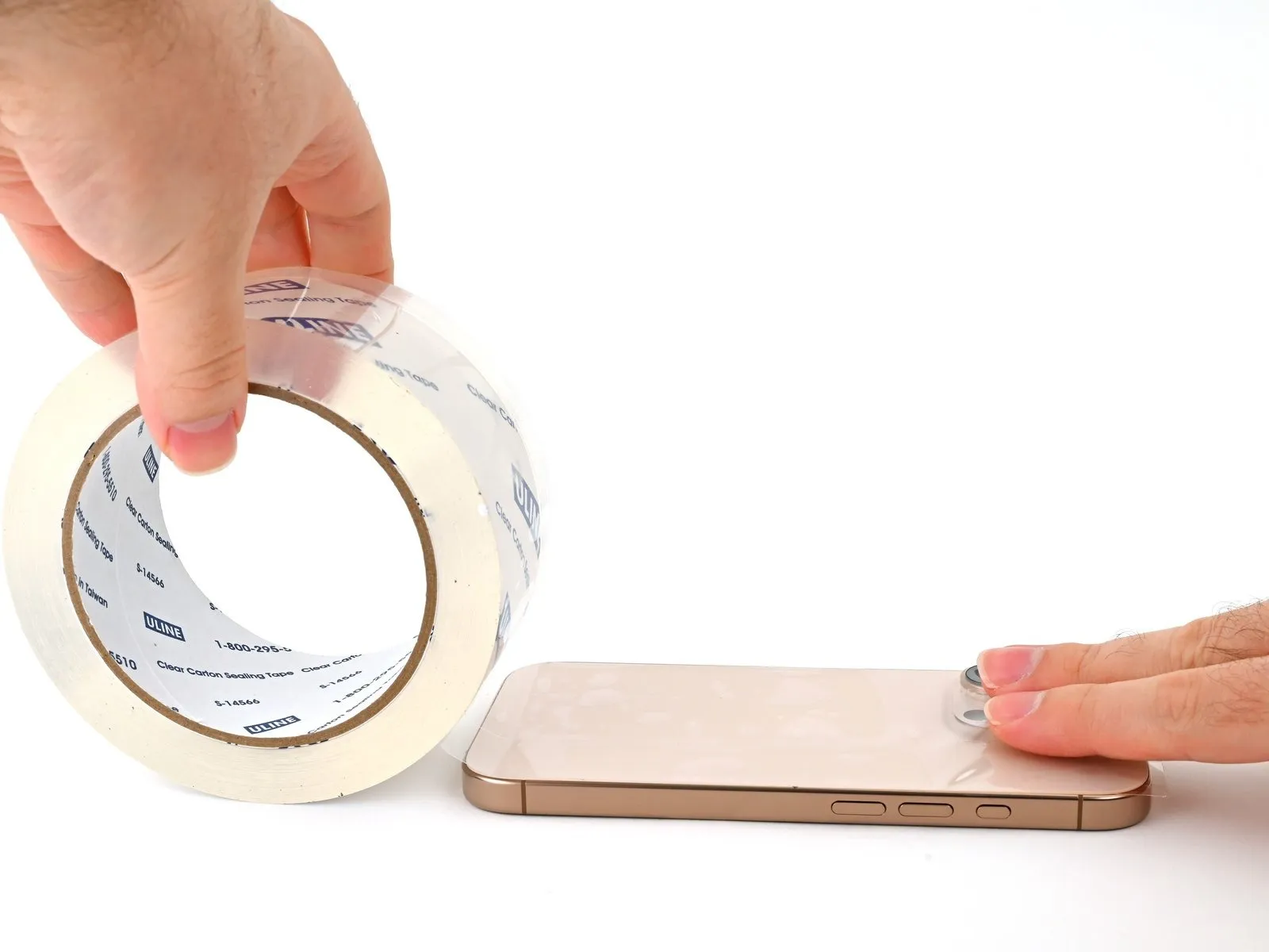
- To prevent injury and simplify the subsequent separation of components, apply several layers of adhesive packing tape across any severely fractured screen or rear glass panel.
- Confirm the presence of a sufficiently sized, uninterrupted surface close to the lower perimeter, allowing for reliable adhesion of a suction cup.
Step 3 | Mark your opening picks


- Excessive insertion of a spudger can potentially harm the device; therefore, it's crucial to implement a marking procedure to avoid such damage.
- Using a precise measuring tool, determine a distance of3 millimetersfrom the pick's distal end and clearly indicate this point with a permanent marking instrument.
- For enhanced precision, consider applying distinct markings to the pick's other corners, each representing a different measurement.
- As an alternative method, secure a coin to the pick's shaft using adhesive tape, positioning it3 millimetersaway from the tip.
Step 4 | Remove the pentalobe screws
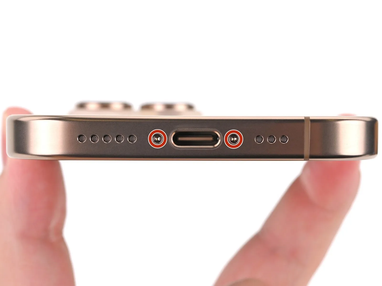

Employ a P2 pentalobe screwdriver for the extraction of the two screws.The screws securing the USB-C port are each 7.4 millimeters in length.These fasteners are located on both lateral aspects of the USB-C port.
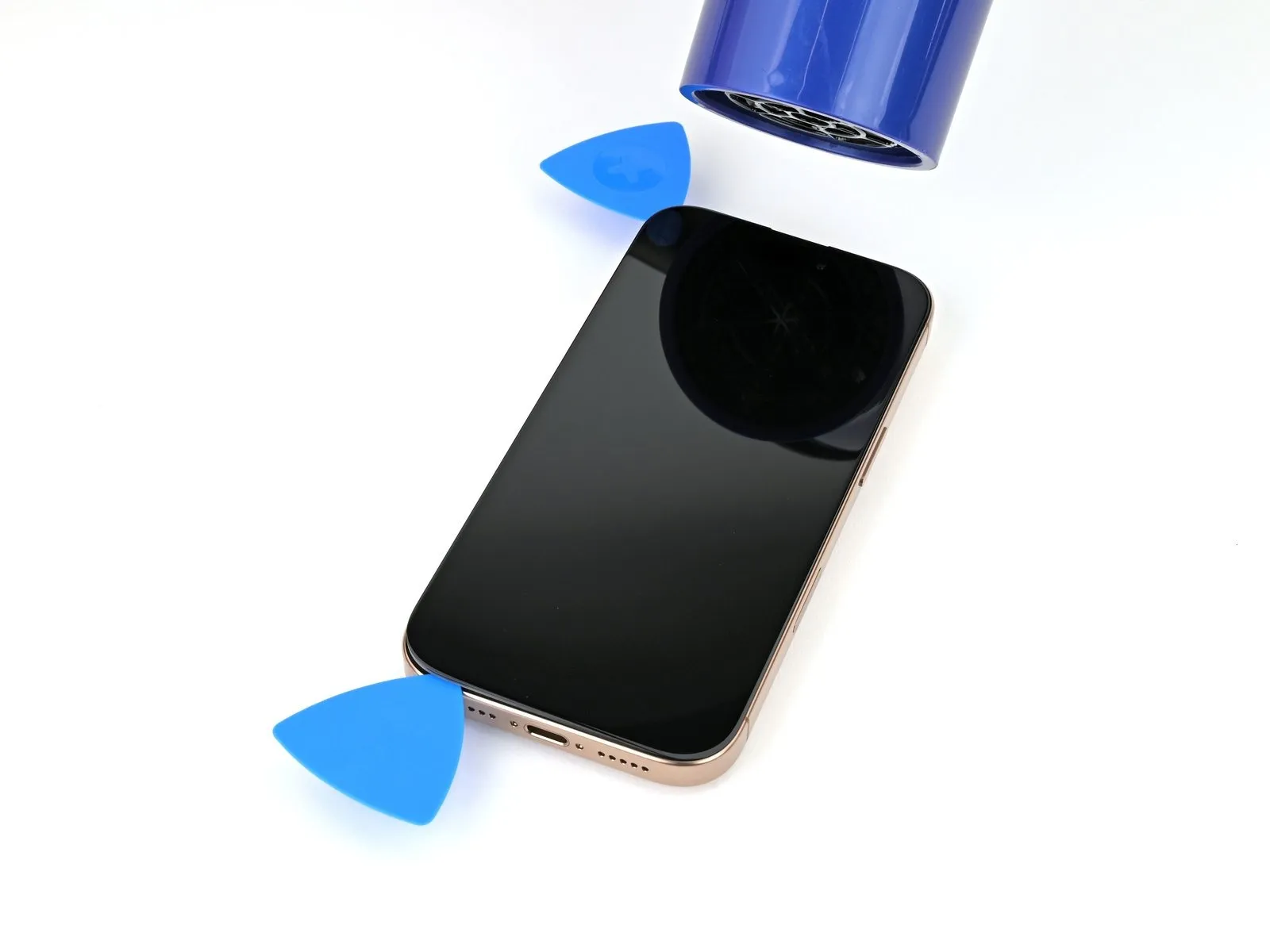
Step 5 | Create a gap with a suction handle
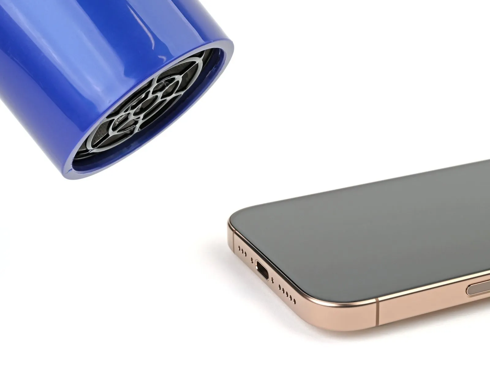
- The subsequent procedures detail the process of establishing a preliminary separation utilizing a suction tool's handle.
- Employing either a hair dryer or a heat gun, warm the lower screen perimeter until the surface reaches a temperature detectable by touch.An iOpener device may alternatively be utilized for this purpose.
- Adhere to the following guidelines to ensure appropriate heating and application of the iOpener.
Step 6
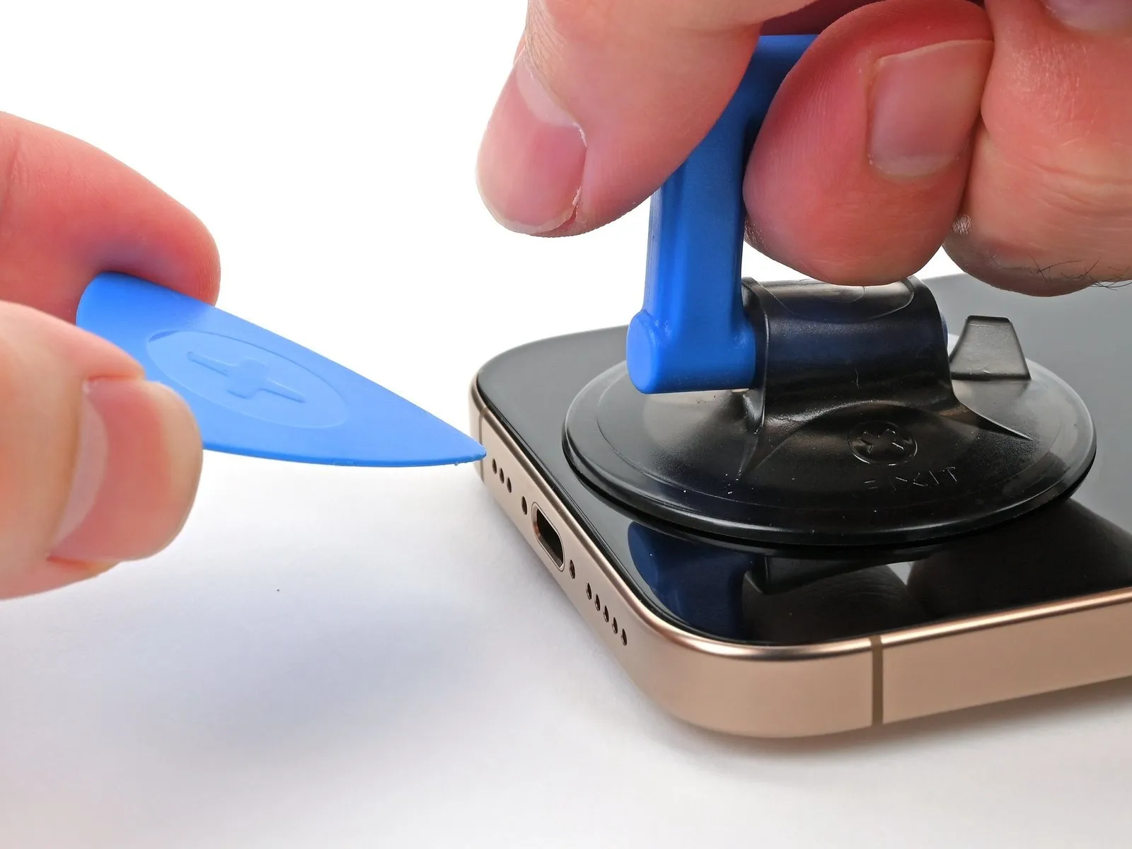

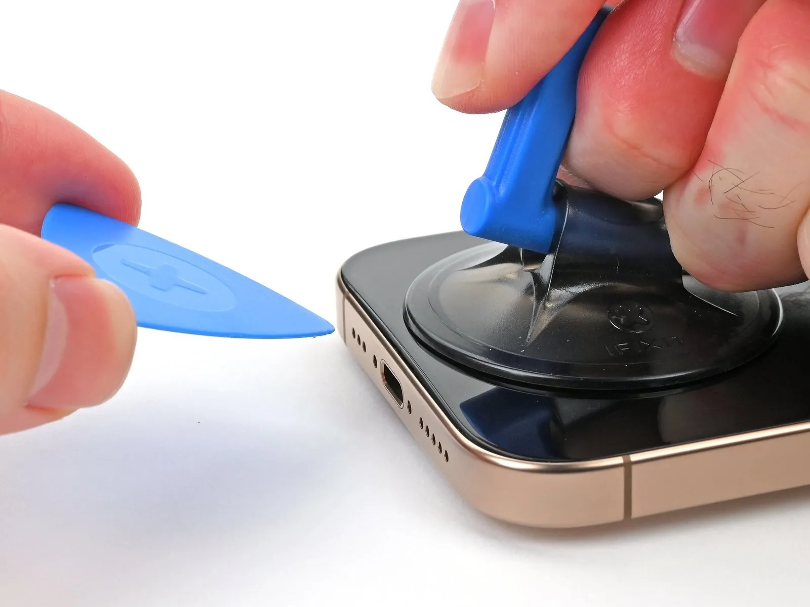
- Secure a suction handle to the lower border of the display assembly.
- Exert a consistent, forceful upward traction on the handle to establish separation between the display and its surrounding structure.
- Should initial attempts at gap creation prove unsuccessful, increase localized heat application along the perimeter and repeat the lifting procedure.
- Carefully introduce the pointed end of a prying tool into the newly formed space.
Step 7 | Screen information

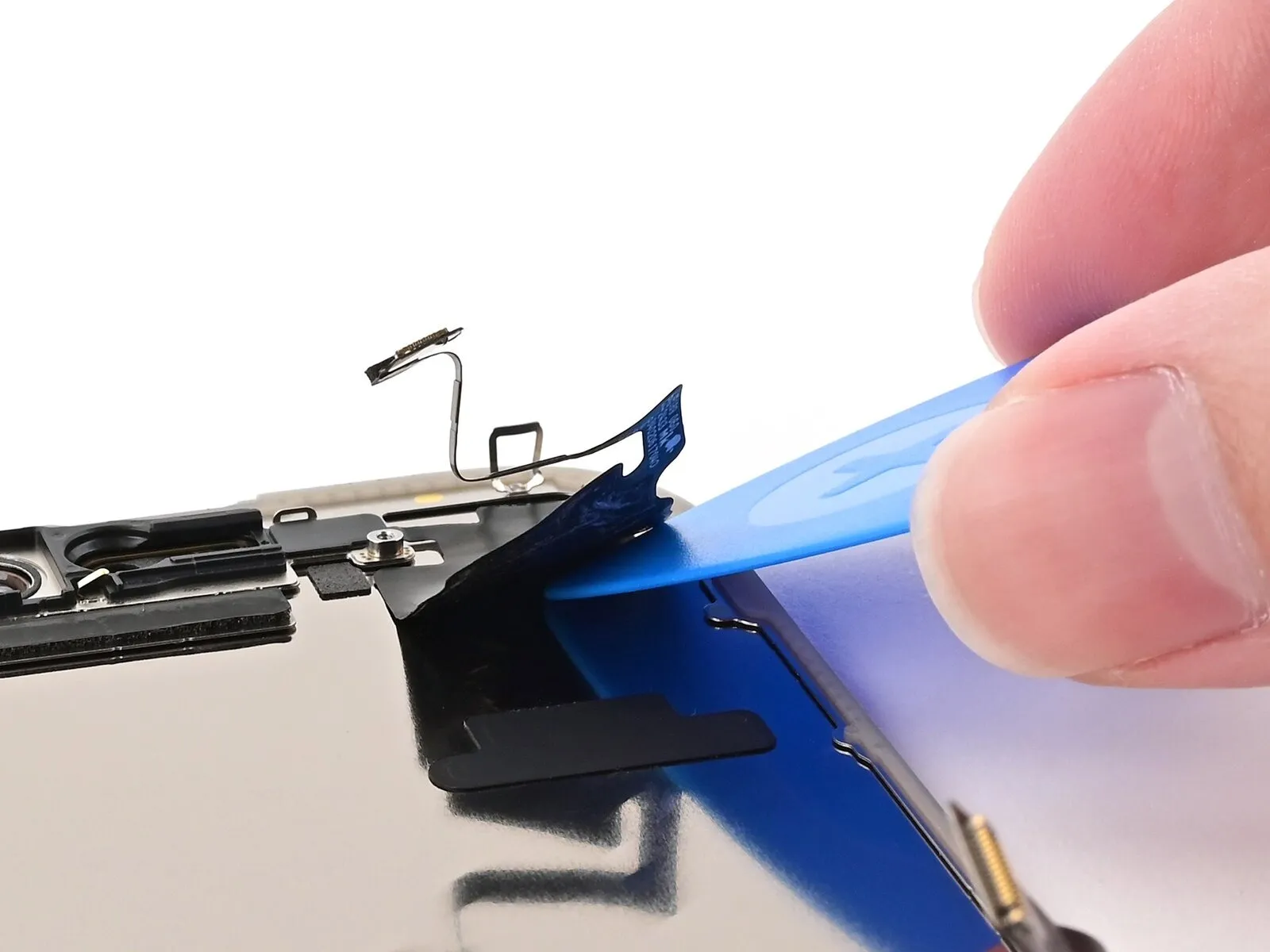
To prevent harm to adjacent components during screen separation, limit the insertion depth of your tool to a maximum of 3 millimeters when releasing the adhesive.
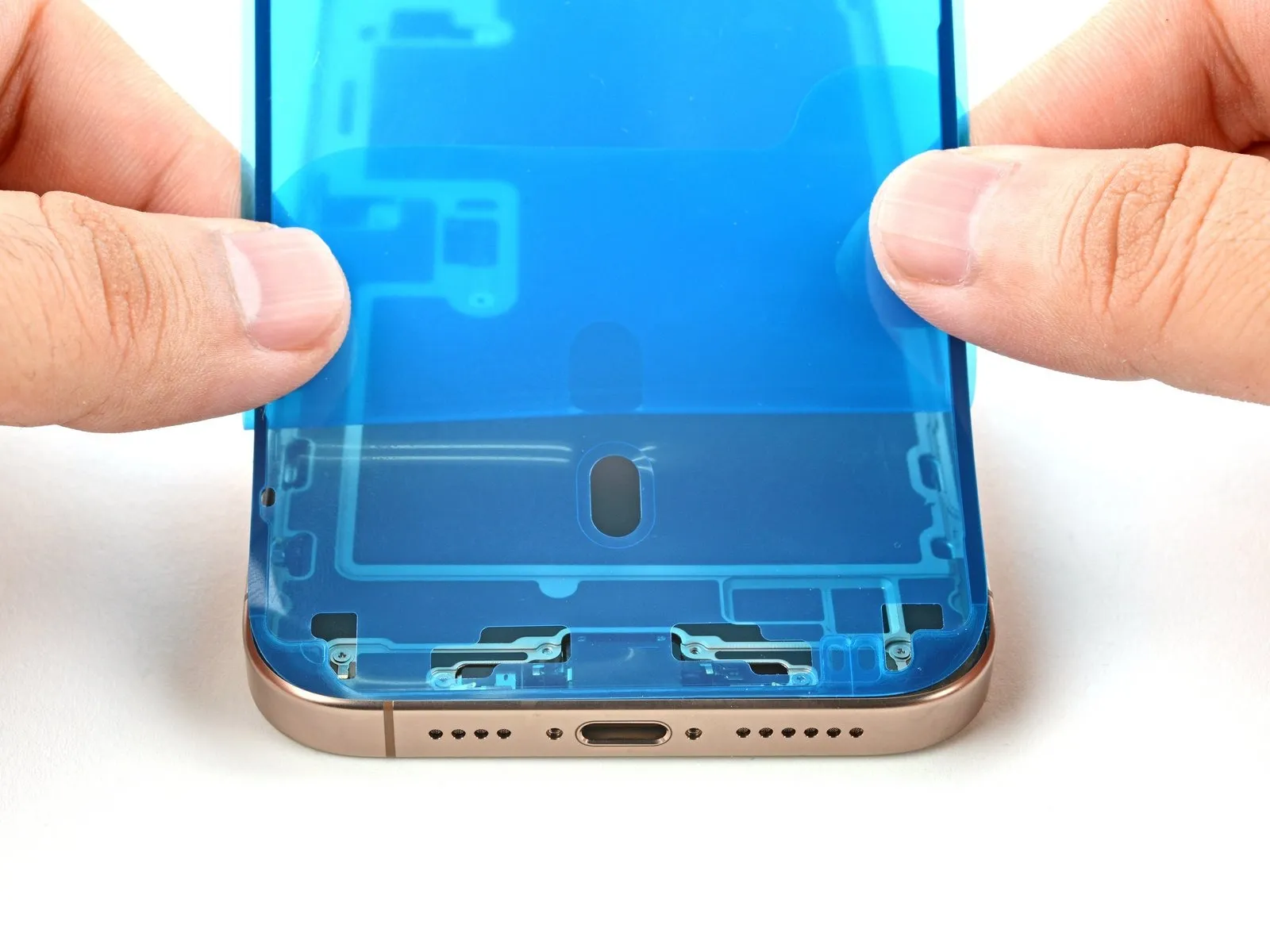
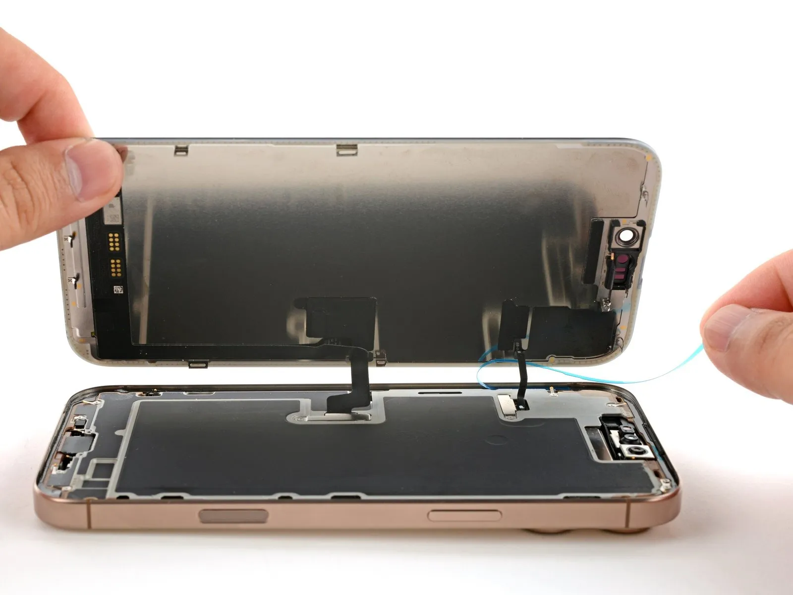
- The display assembly is connected via two fragile cables: one located directly above the Action button and the second positioned approximately midway down the left side of the iPhone’s chassis.
- A series of sensitive spring contacts are situated along the iPhone's outer edges, requiring careful handling.
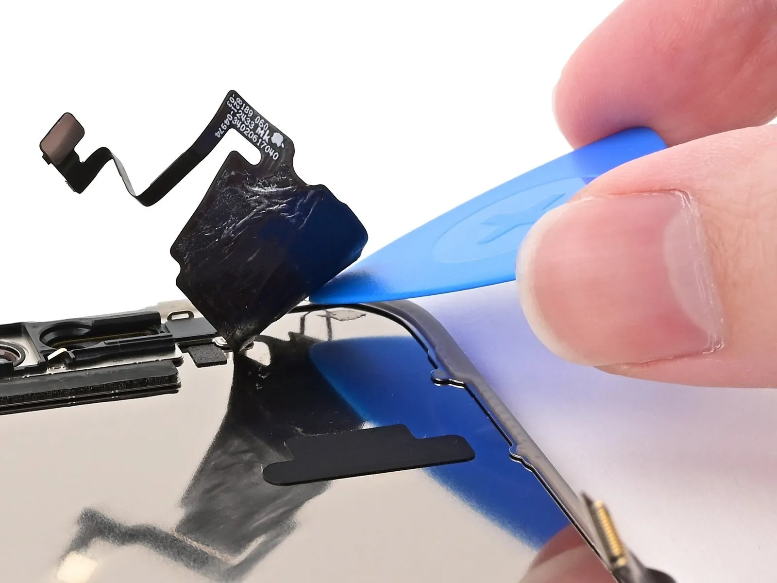
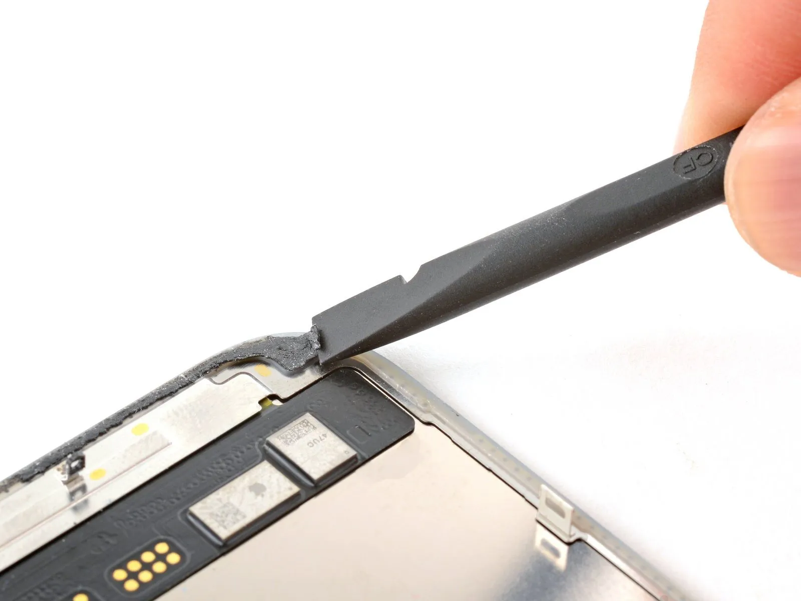
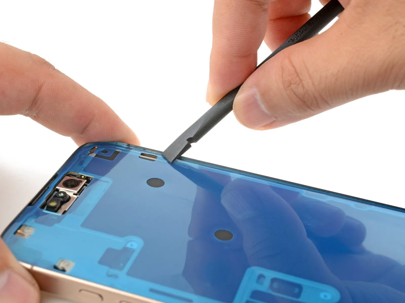
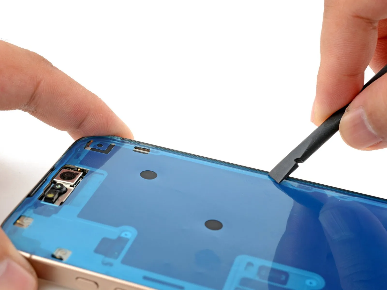
Step 8 | Slice the bottom edge adhesive
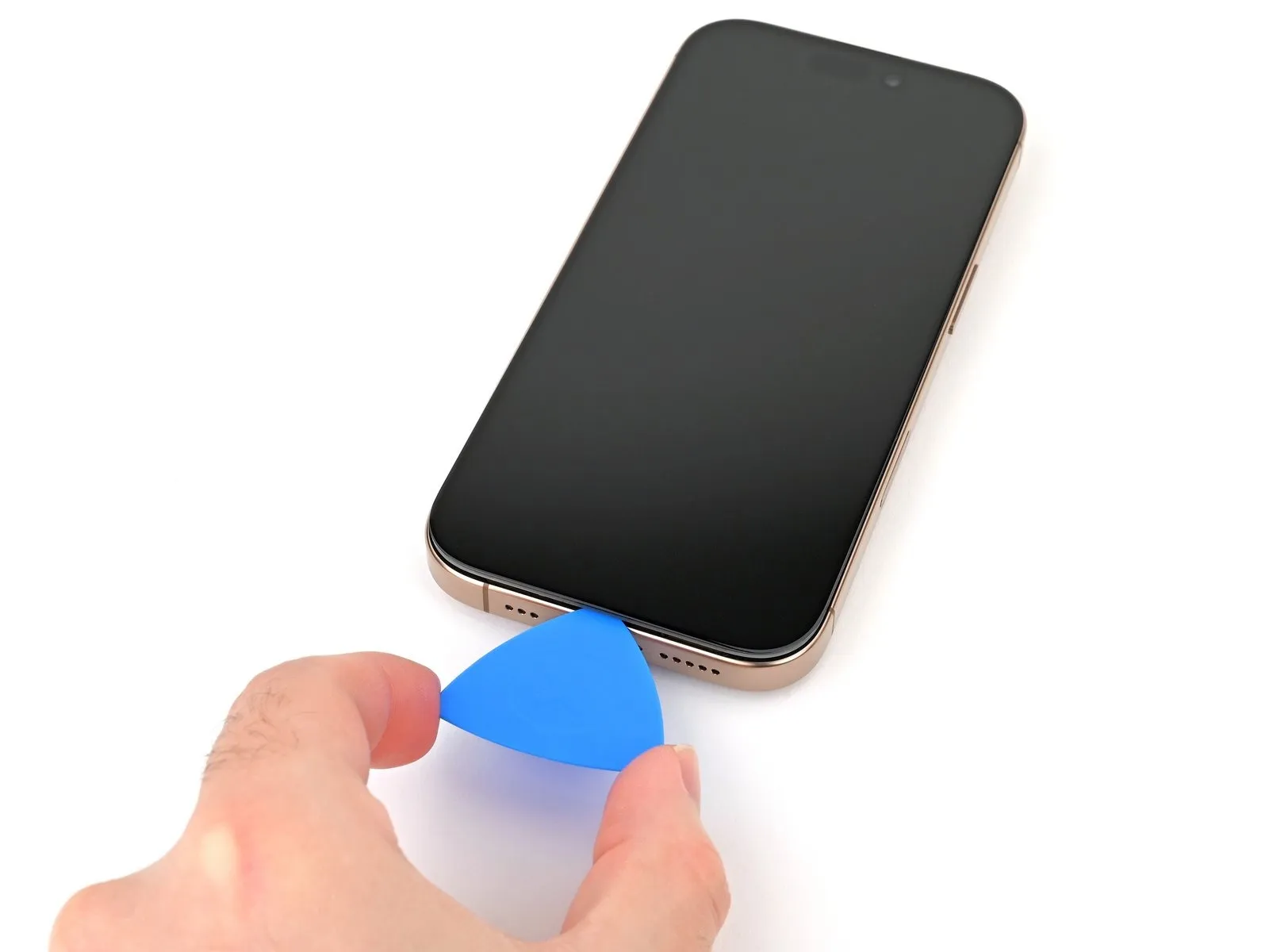


- Utilize a specialized opening pick, moving it along the lower perimeter to separate the adhesive bond.
- Ensure the pick's insertion depth remains below 3 millimeters, safeguarding the delicate spring contact points from potential harm.
- Should the adhesive present resistance during separation, apply localized heat for approximately one minute to soften its bond.
- Maintain the opening pick's position within the lower-left corner to inhibit the adhesive's ability to reattach.
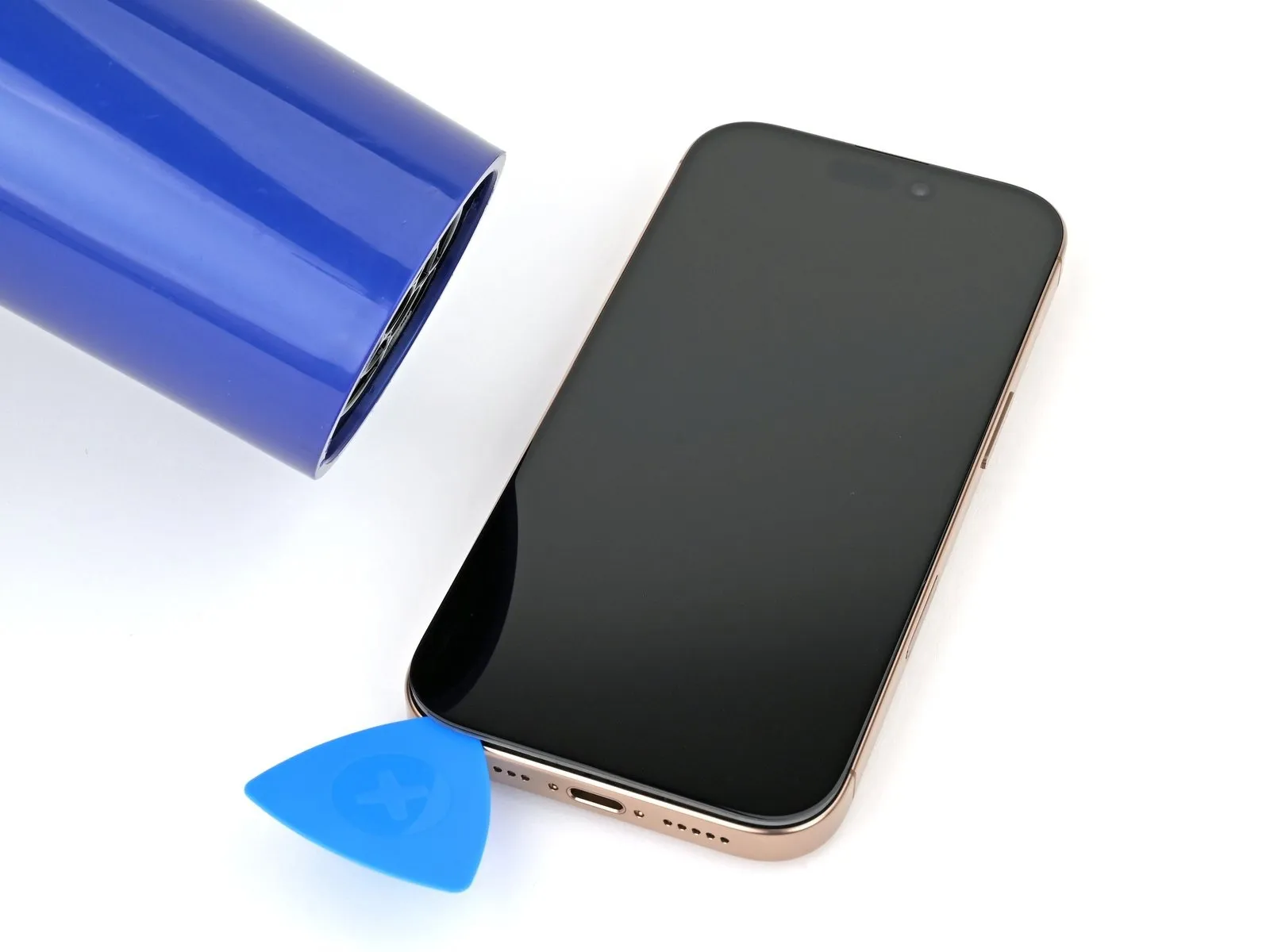
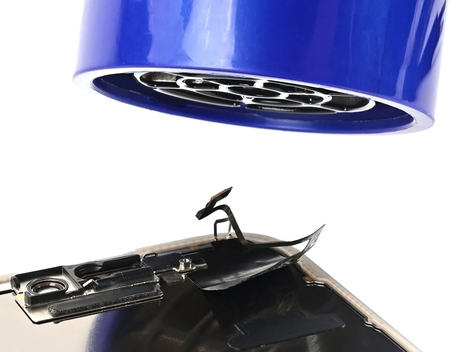
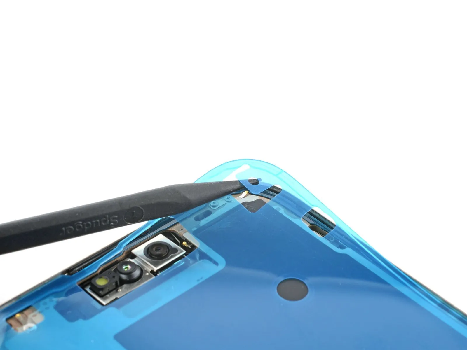
Step 9 | Heat the left edge
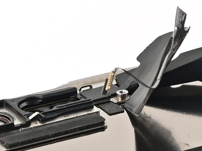
Step 10 | Separate the left adhesive


- To prevent harm to the spring contacts and associated wiring, ensure the pick's insertion depth remains no greater than 3 millimeters.Position a supplementary opening pick within the lower-left area, situated near the already inserted pick.
Move the second opening pick along the screen's left border, facilitating adhesive separation and disengagement of the metal clips.
The audible and tactile sensation of the metal clips releasing will indicate their successful dislodgement during movement.
Maintain the initial opening pick’s position in the upper-left corner, which will inhibit the adhesive from re-bonding.
Care must be taken to limit pick insertion to a maximum of 3 mm to safeguard the delicate spring contacts and wiring harnesses.
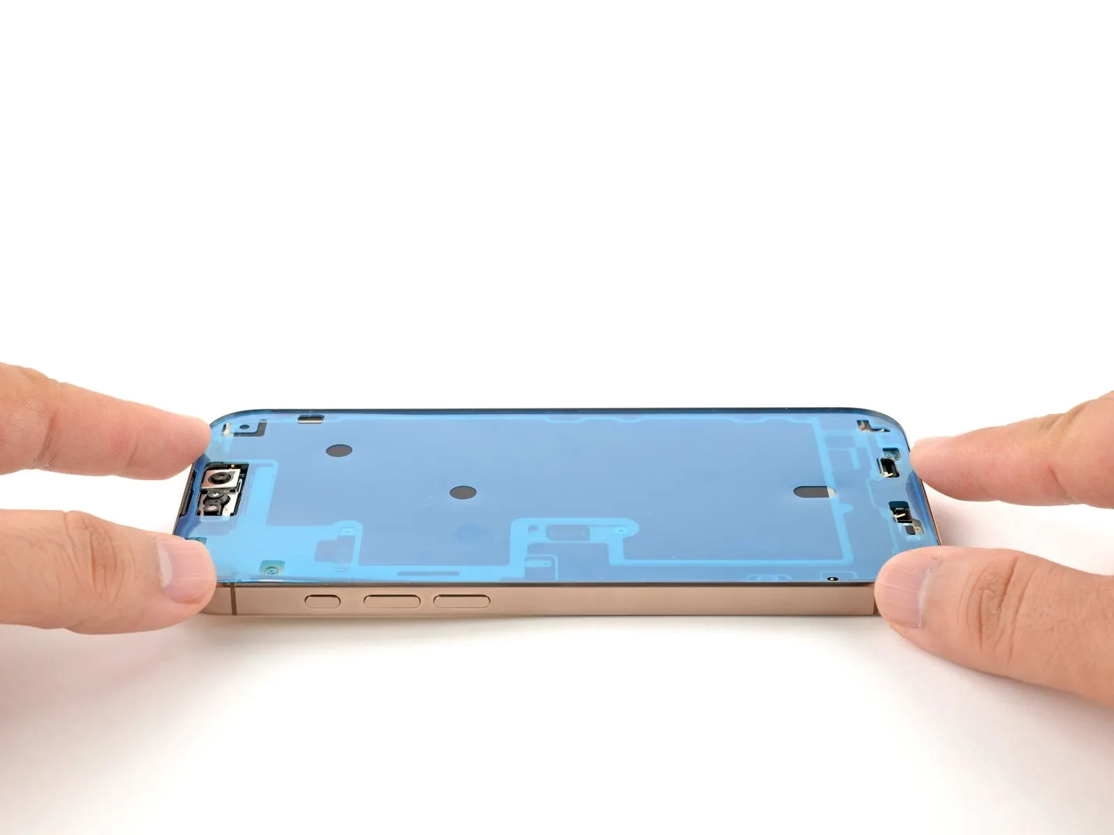
Step 11 | Separate the remaining adhesives


Continue the process of applying heat and separating the display assembly from the frame, working along the entirety of the remaining screen borders.
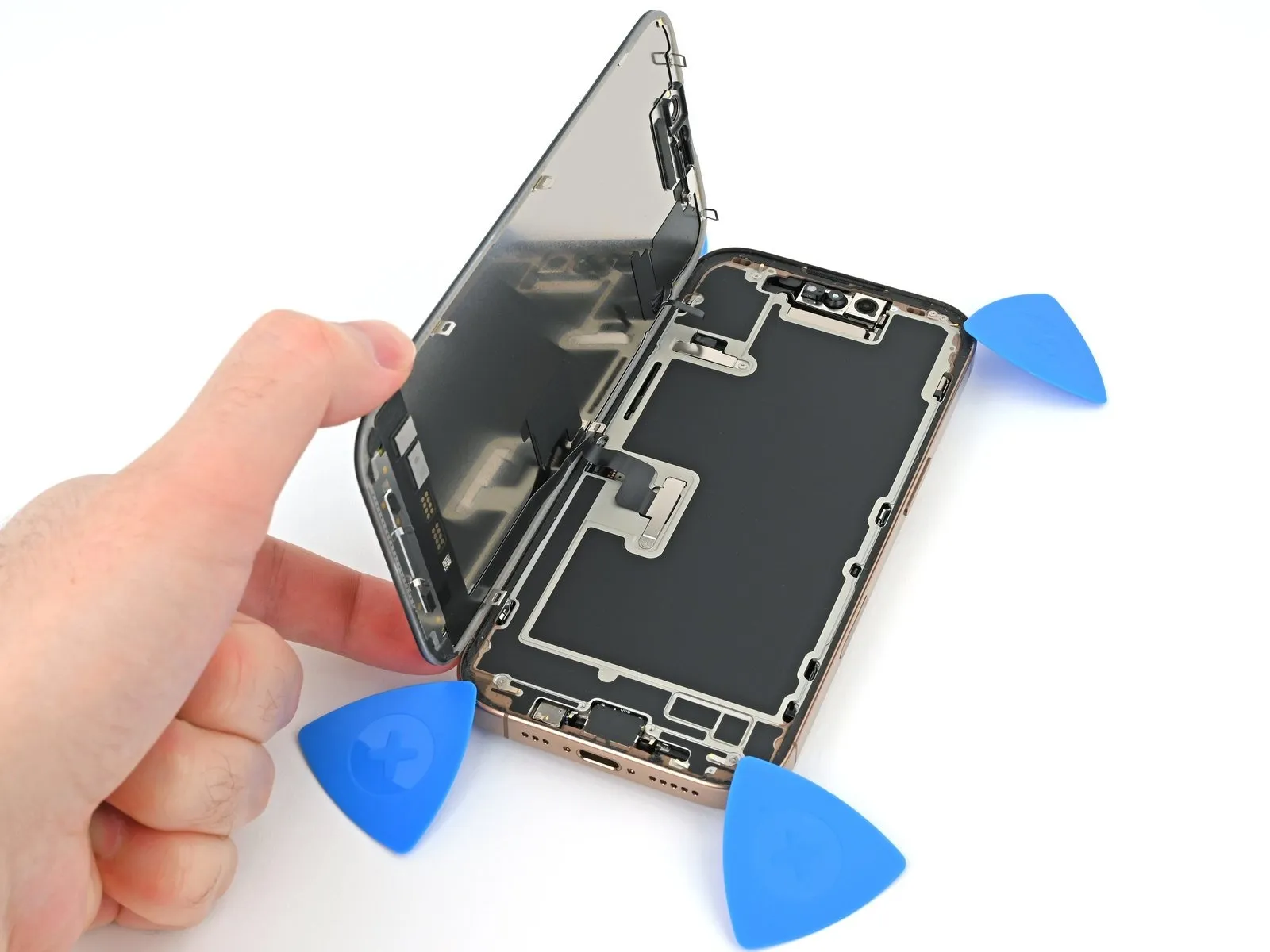
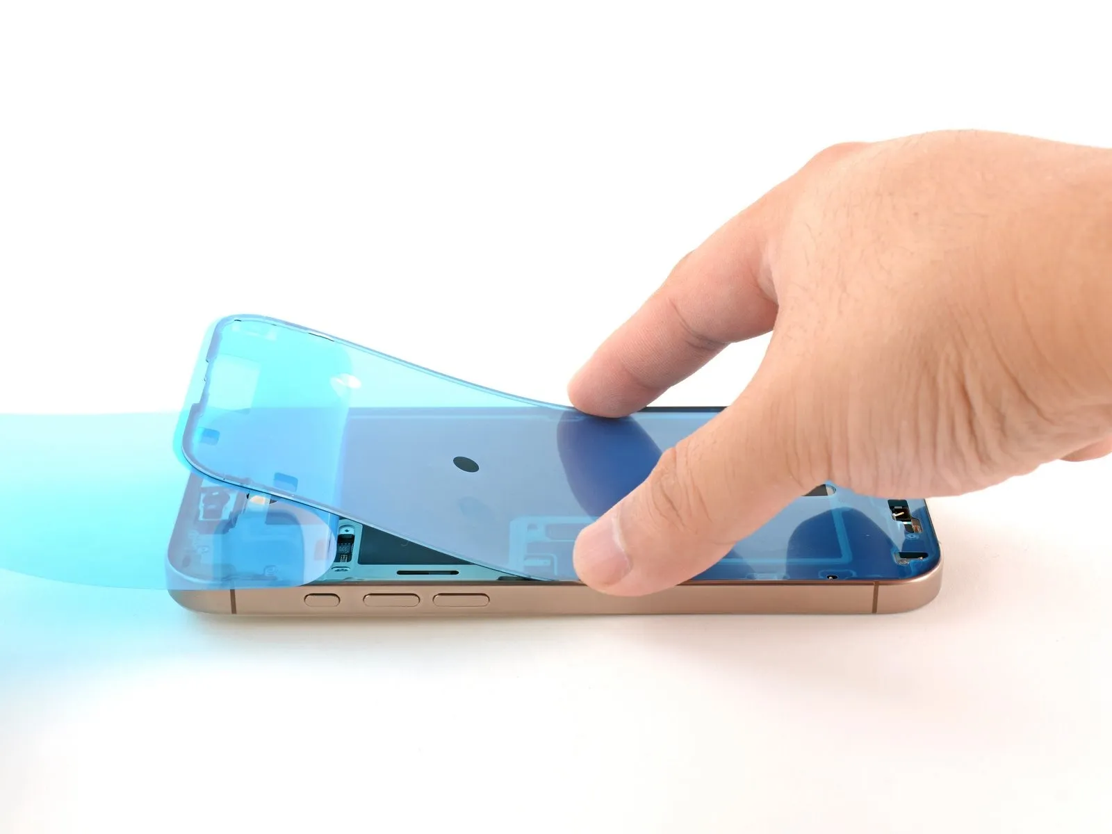
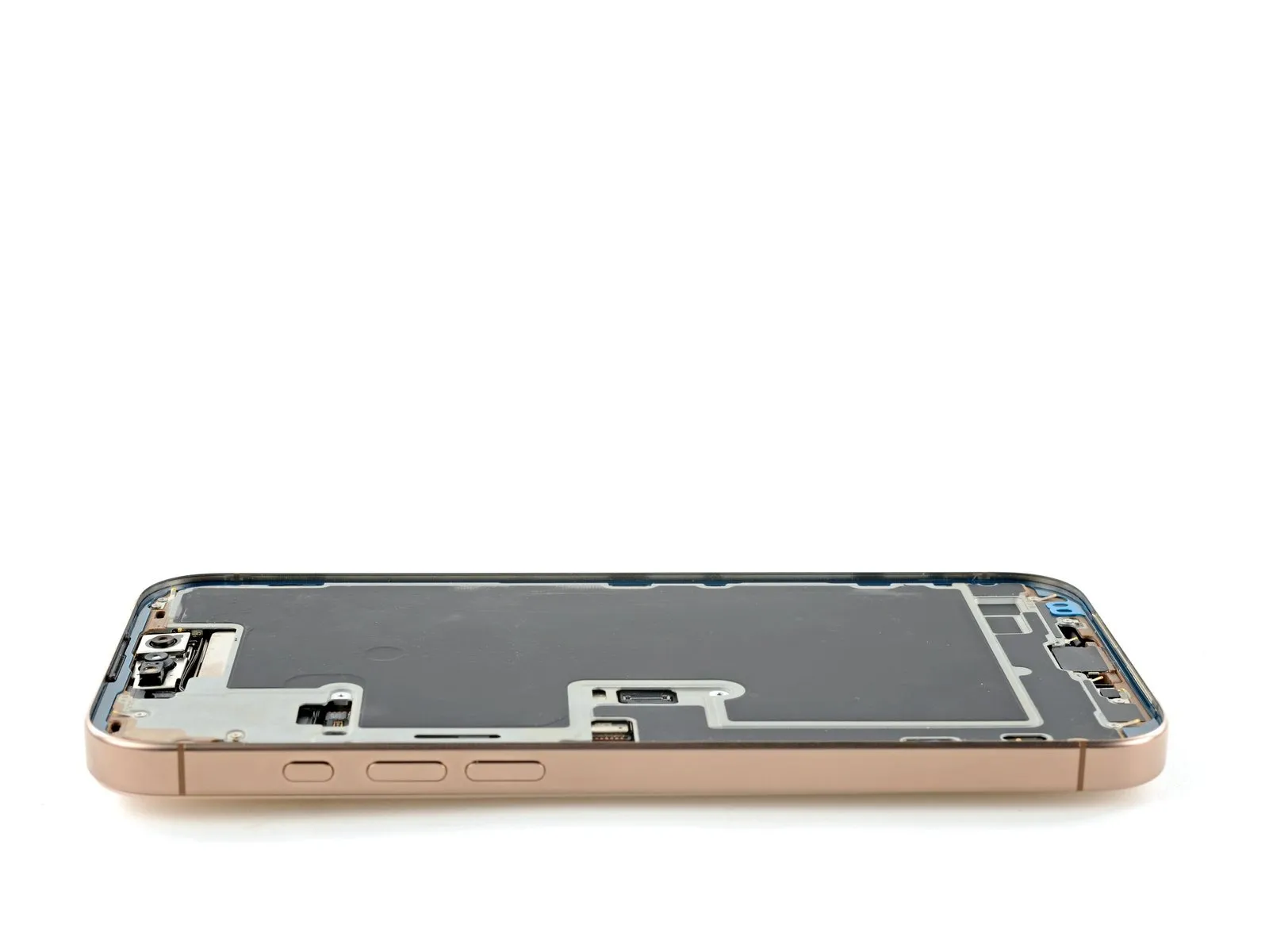
Step 12 | Swing open the screen
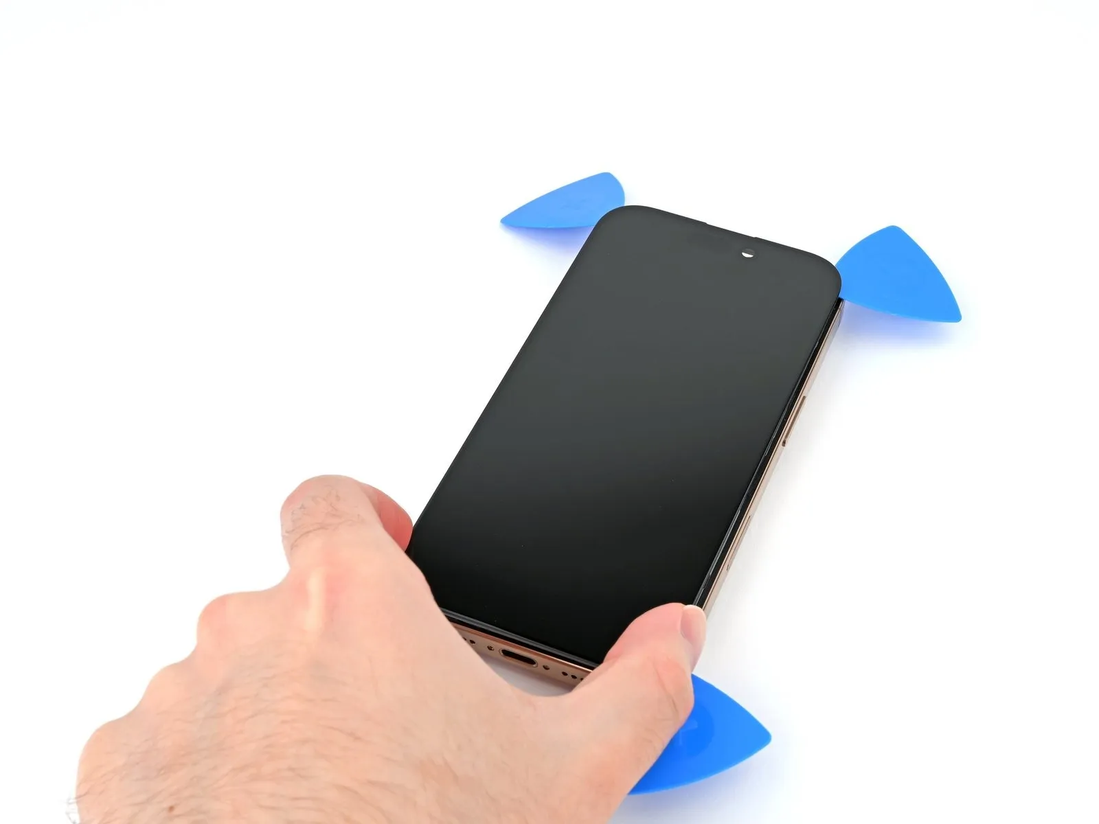

Ensure the display assembly is completely detached from the chassis; if resistance is encountered, re-examine the surrounding edges with the pick, meticulously searching for any remaining adhesive or secured fasteners.
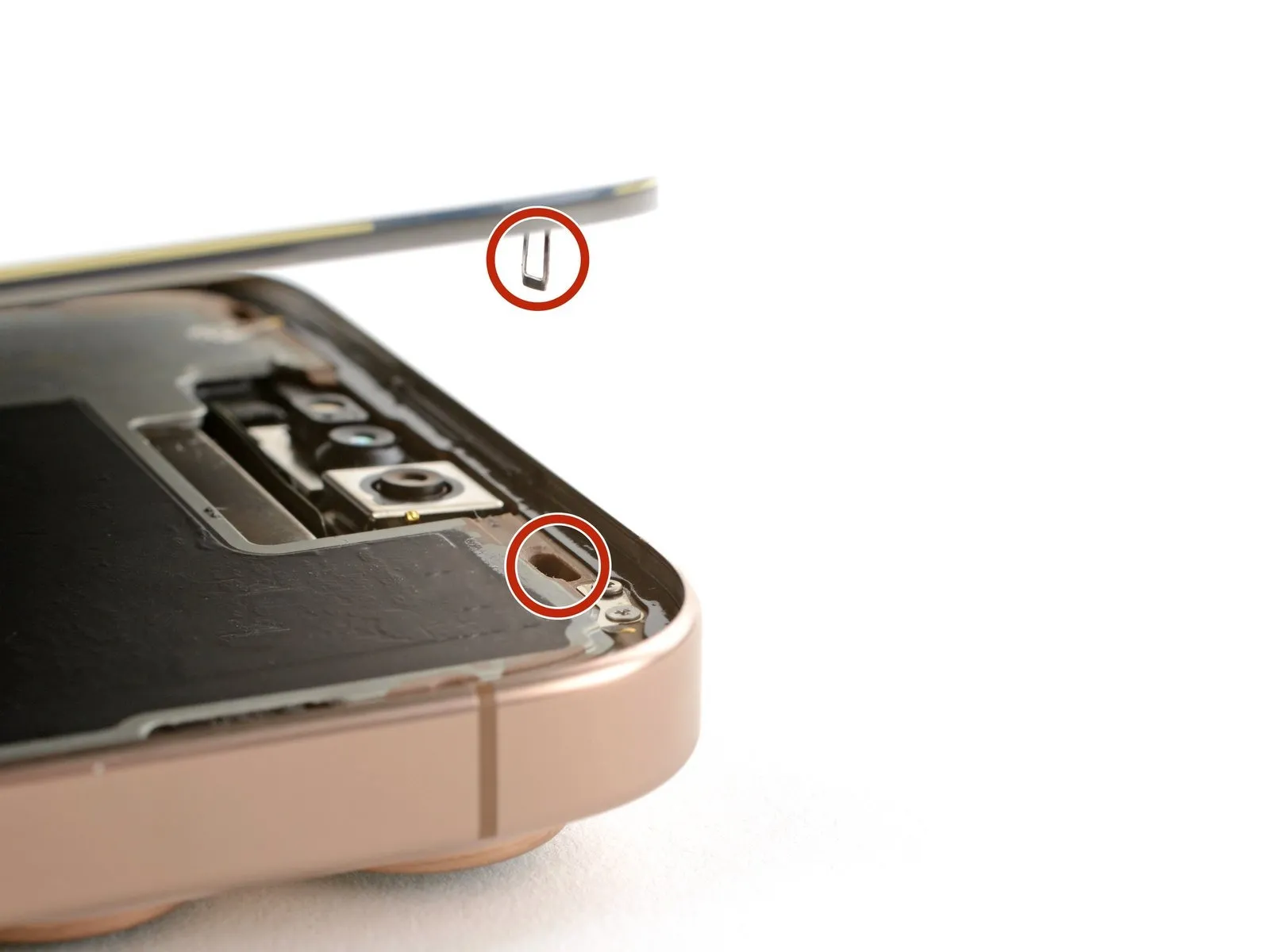
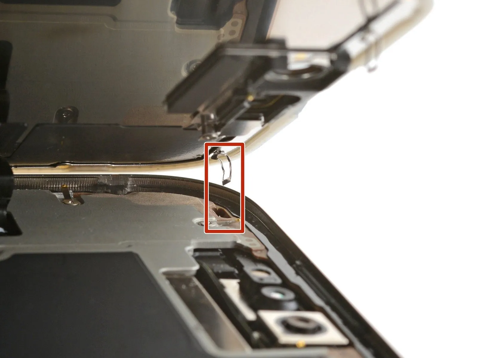
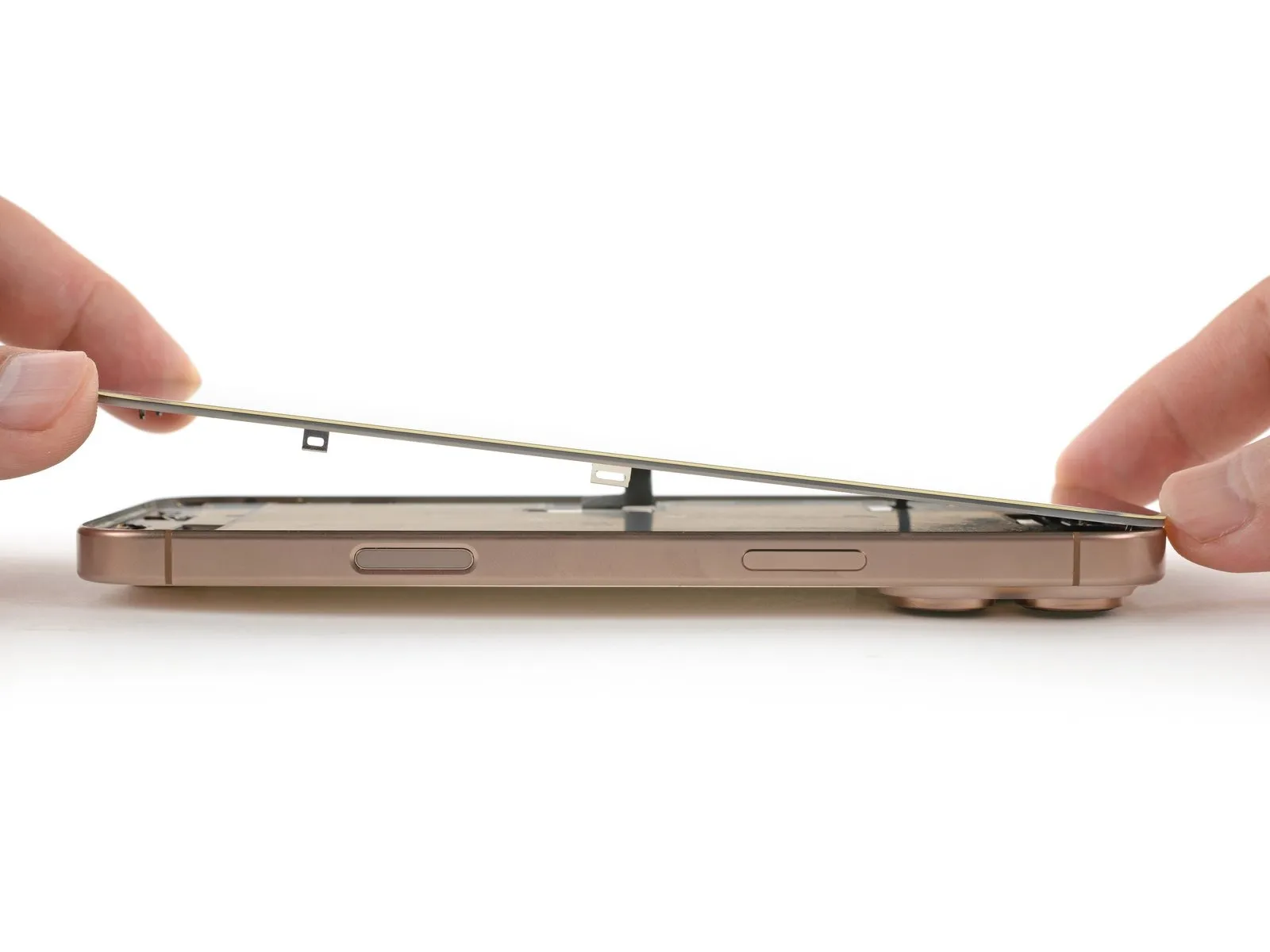
Elevate the display panel vertically, exercising caution to permit the retaining clips situated along the extended sides to disengage from the frame.
Pivot the display assembly over the left-hand side of the iPhone, then position it horizontally on your workspace.
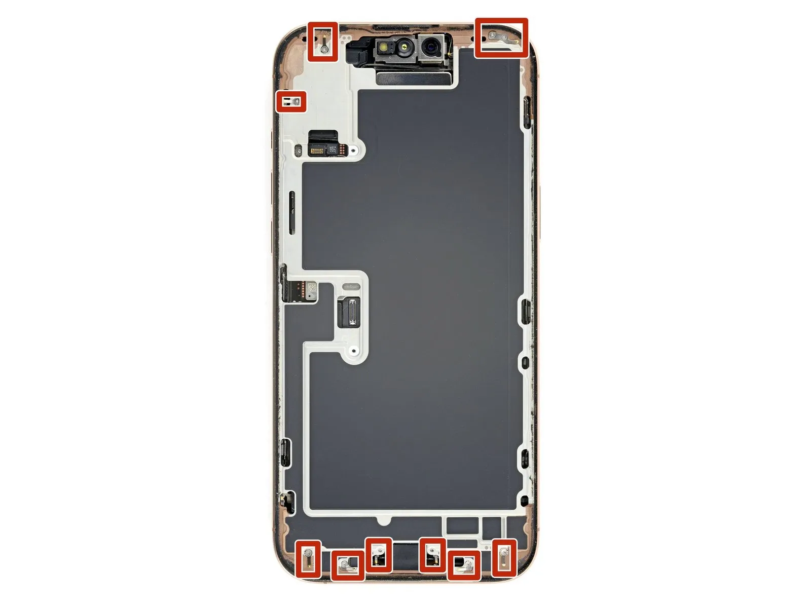
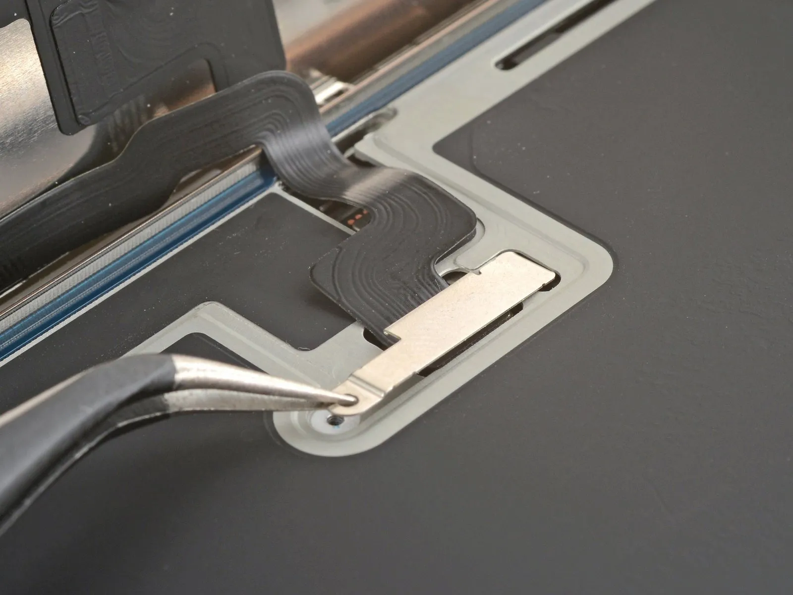
Step 13 | Remove the connector covers

- Employ a specialized tri-point Y000 driver for disassembly.The two fasteners utilized are 1.3 millimeters in length.These screws maintain the security of the front sensor and display connector covers.Removal of the screws is necessary to access the covers.A tri-point Y000 driver is the appropriate tool for this task.
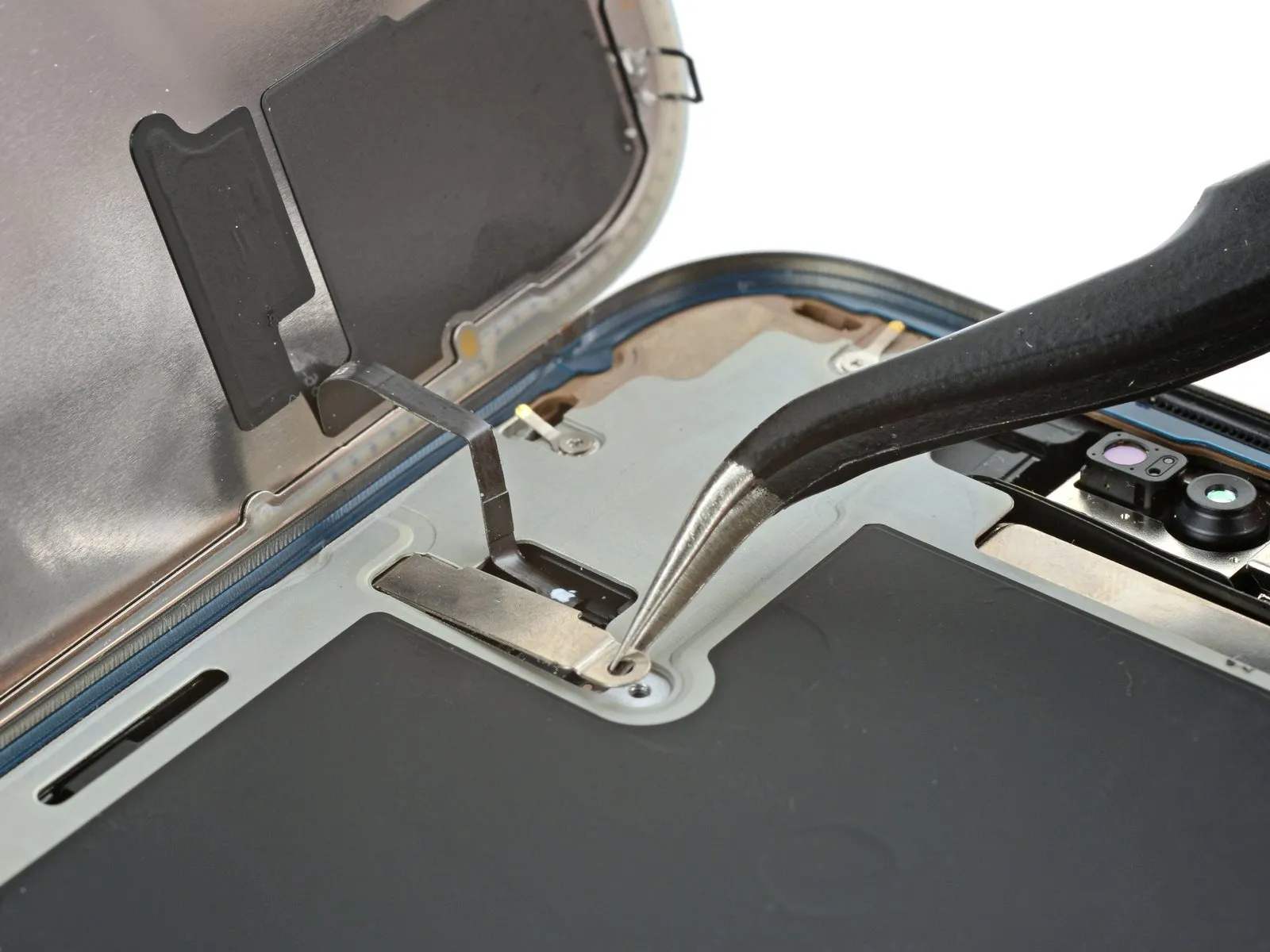
Step 14

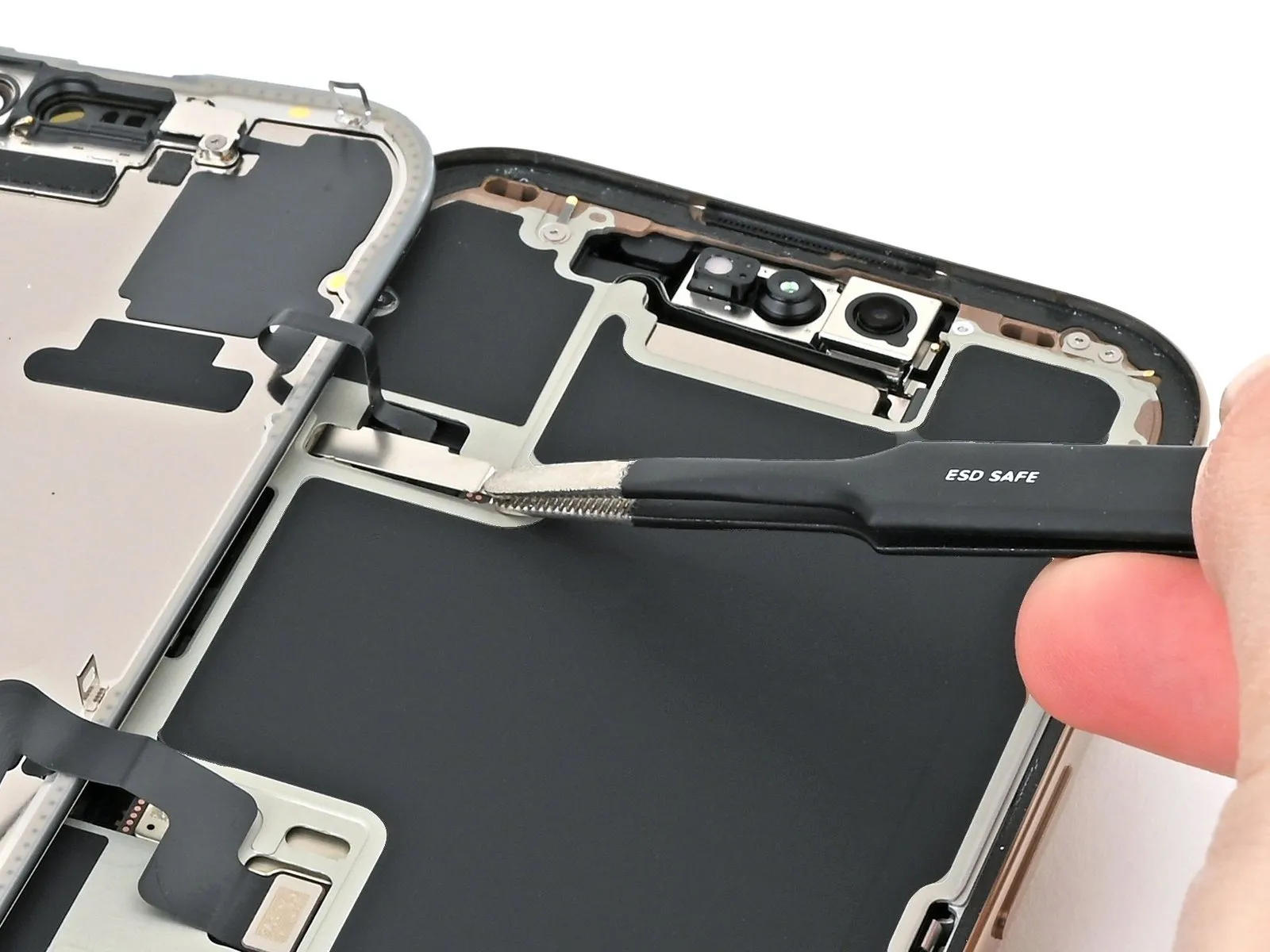
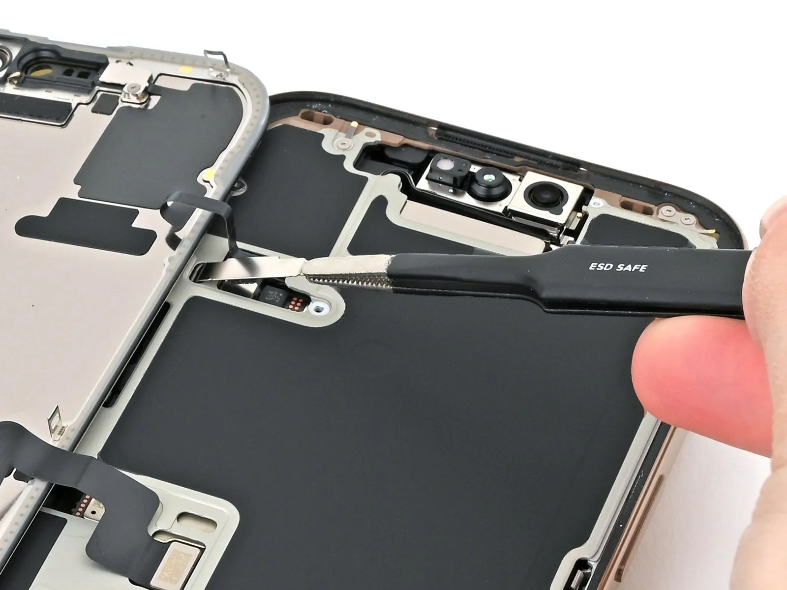
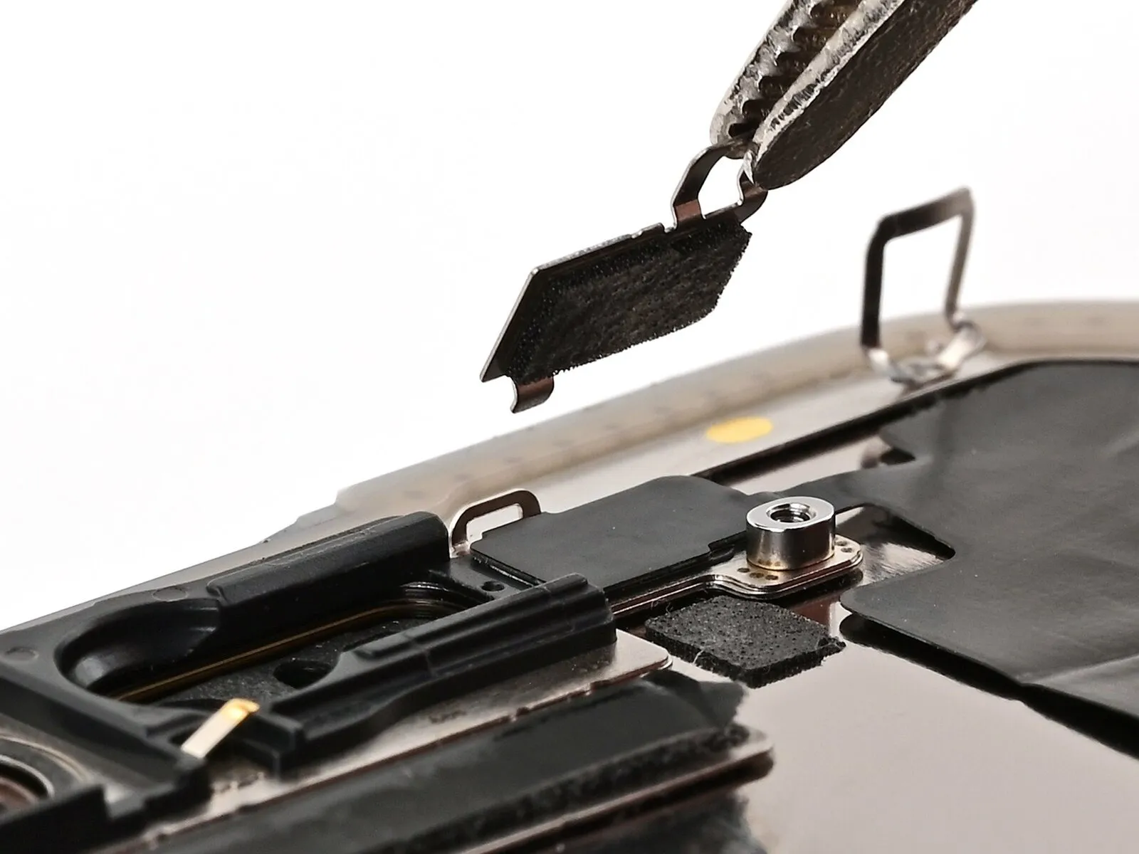
- Employ tweezers to secure the front sensor connector cover's proximity to the screw aperture.
Elevate and detach the cover from its position.
Step 15
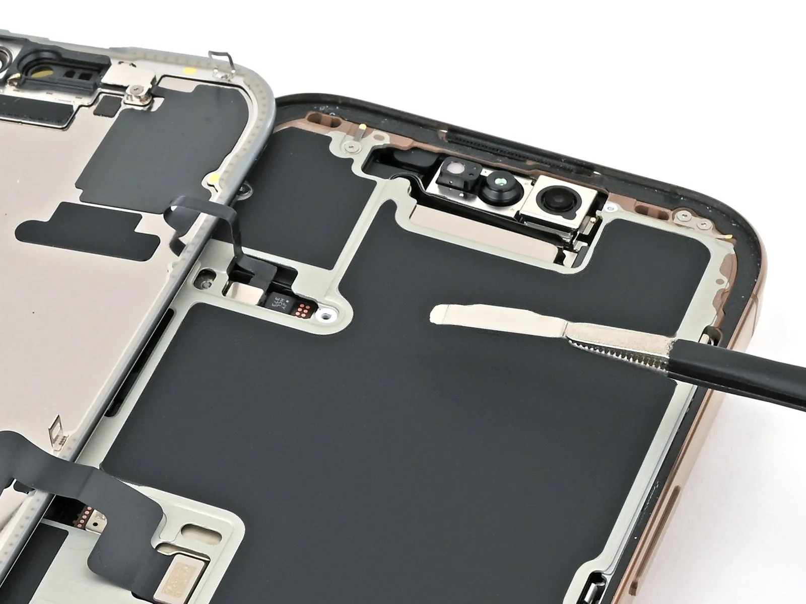
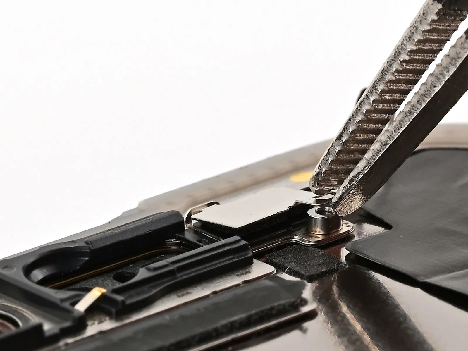
- To ensure consistent results, perform the identical procedure on the remaining cover.
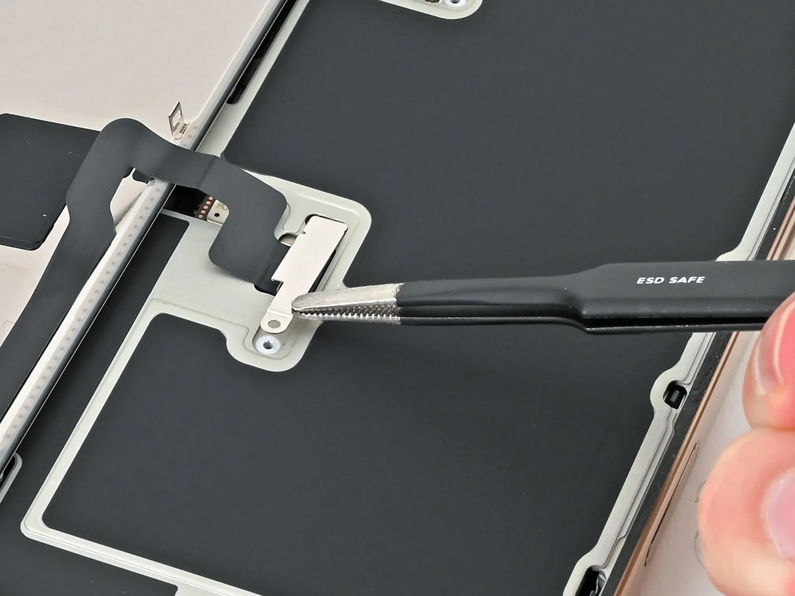
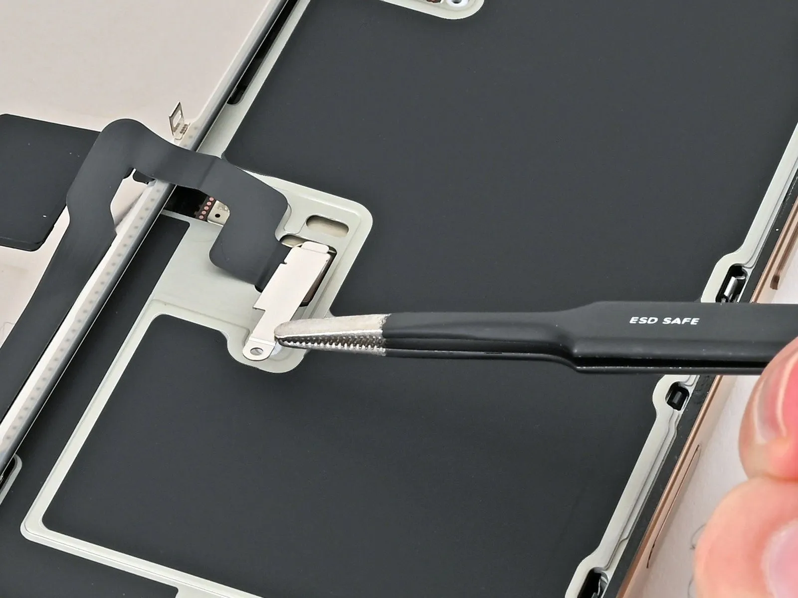
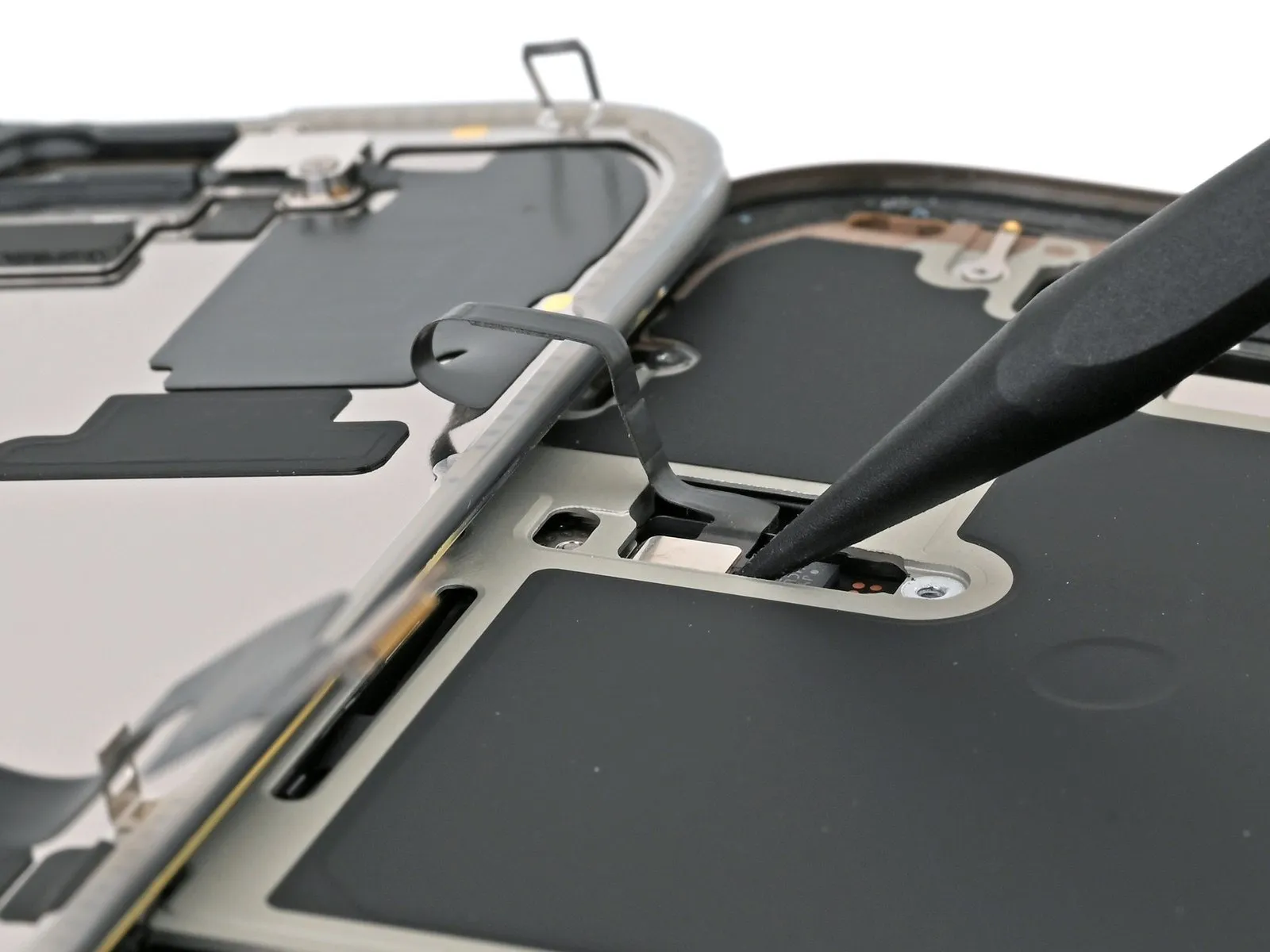
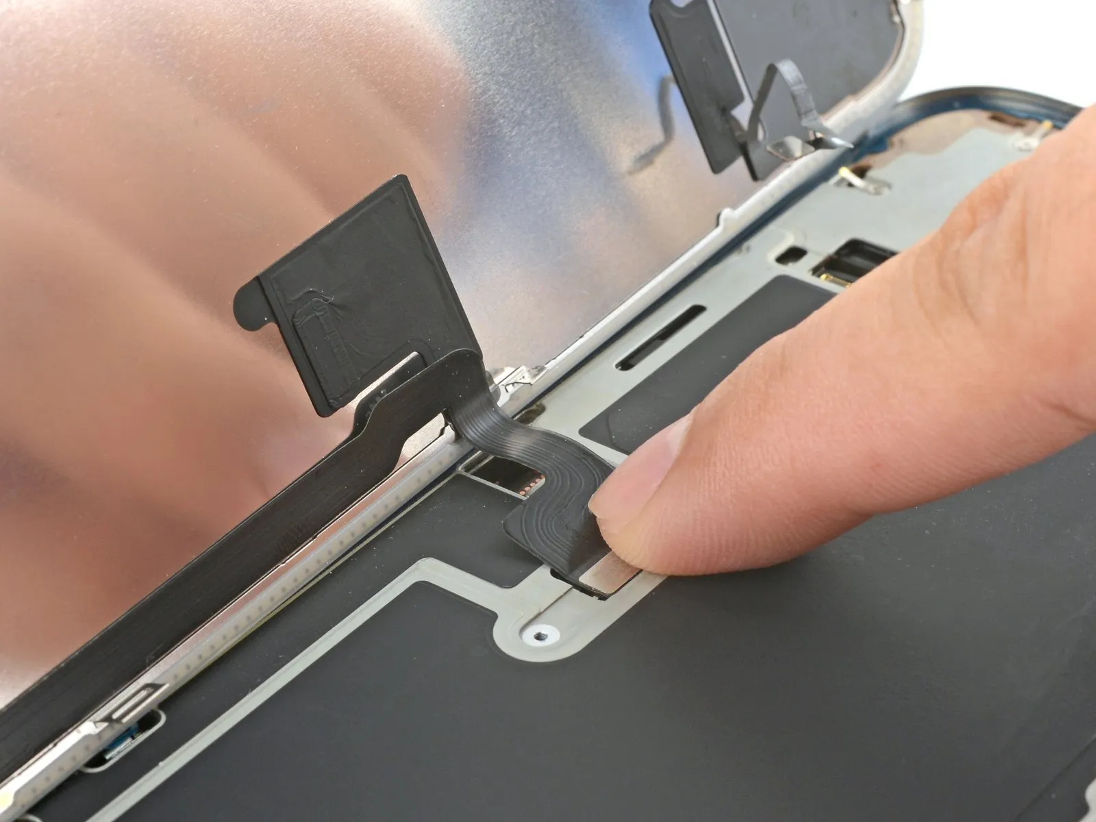
Step 16 | Disconnect the screen


- Employ the pointed end of a spudger to carefully lift and detach the display press connector.The display press connector must be separated from its position by applying gentle force with a spudger's tip.To release the display press connector, utilize a spudger, ensuring the tip is used for precise prying and disconnection.
Step 17
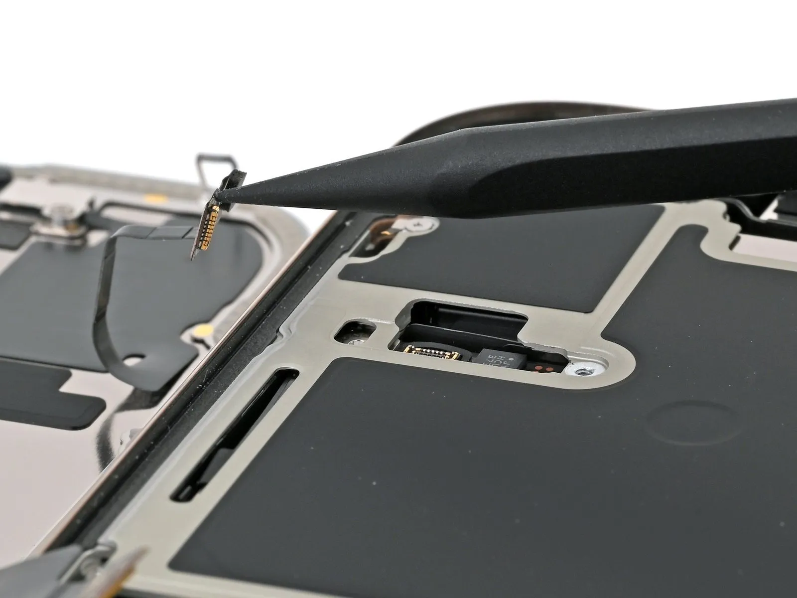
Step 18 | Remove the screen
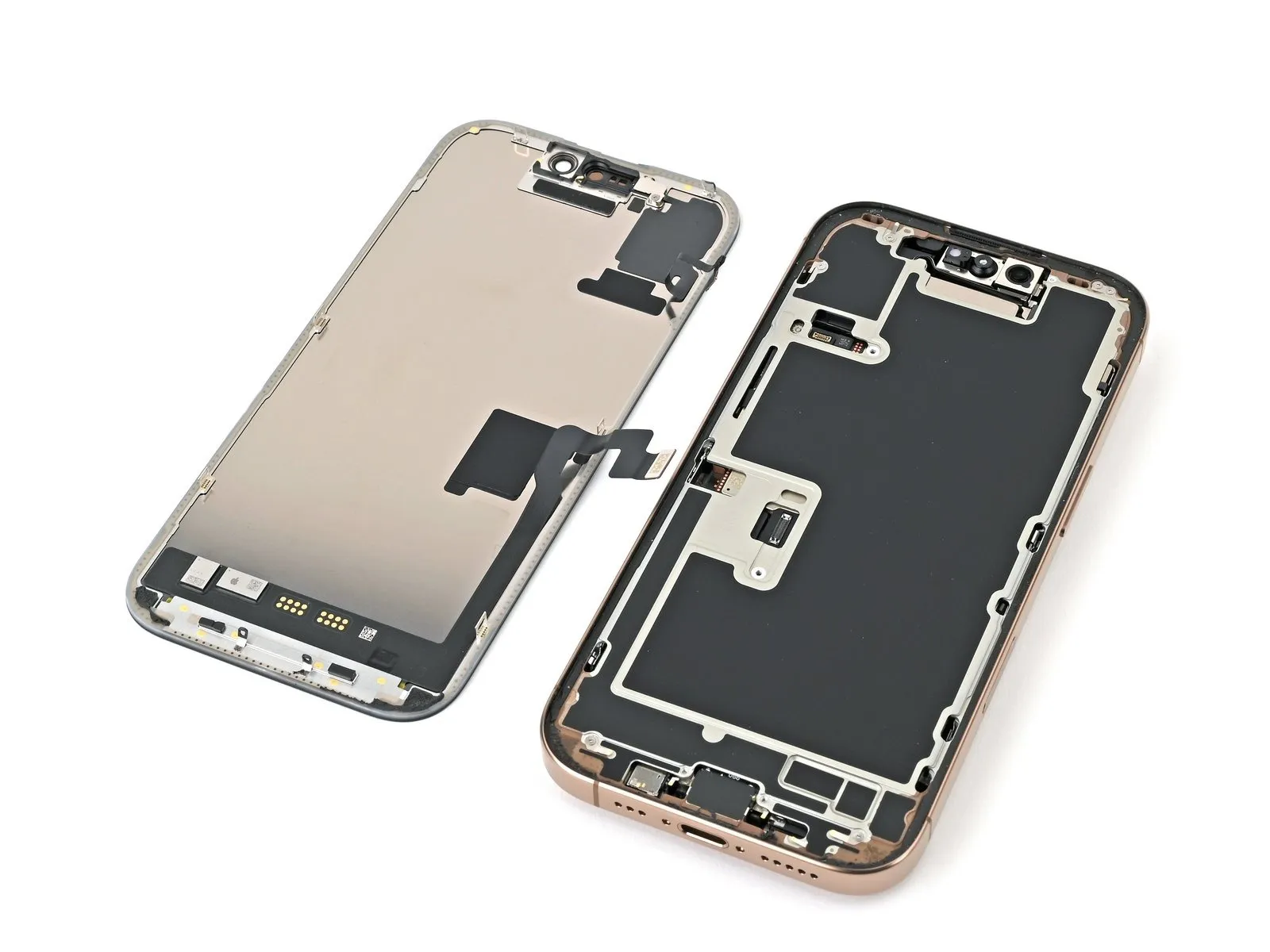
Step 19 | Disassembly complete

- Having finished the disassembly process, the subsequent instructions detail the reassembly procedure for your iPhone; while some images depict the Pro Max variant, the steps are applicable to the Pro model as well.
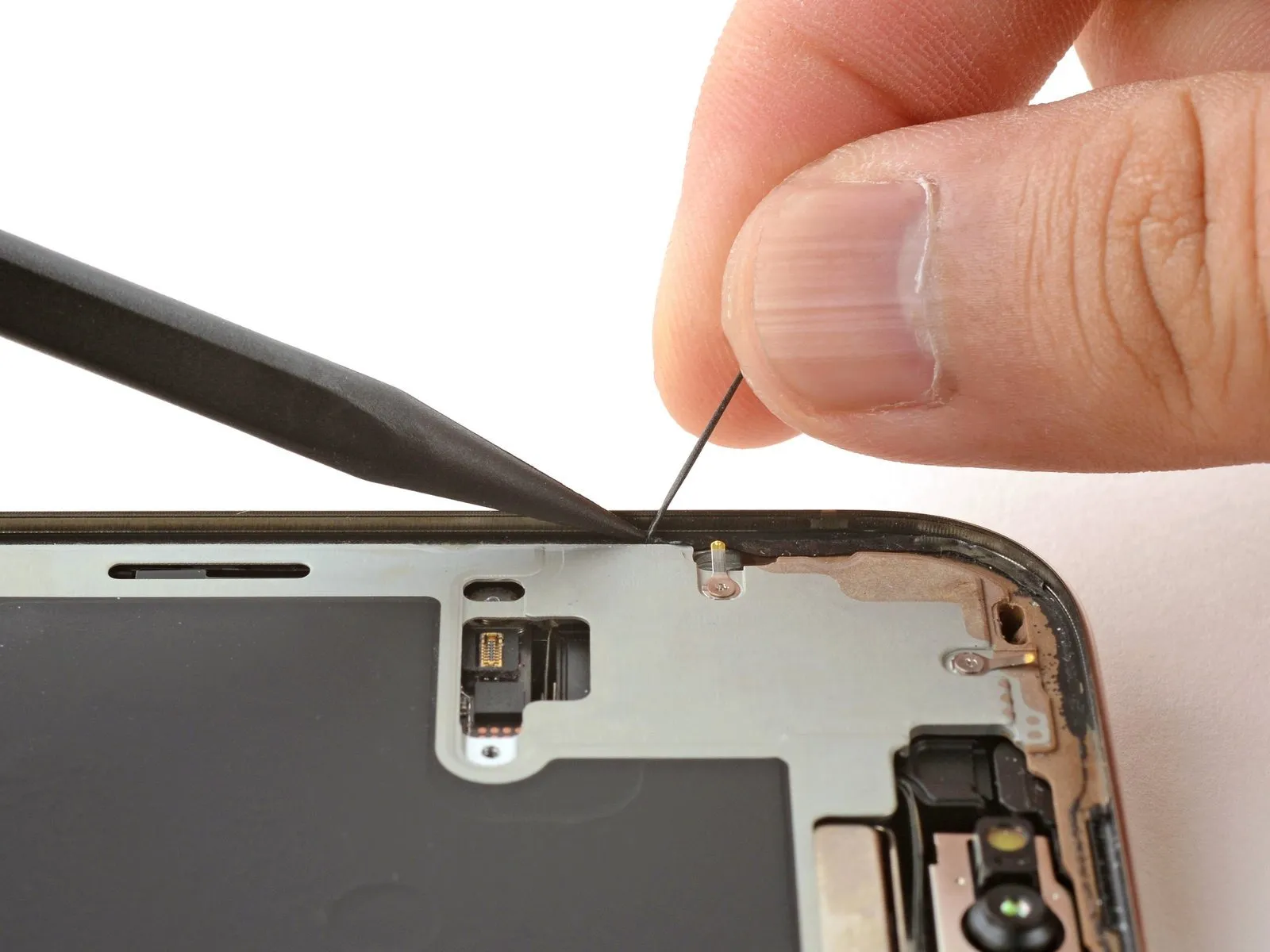
Step 20 | Ambient light sensor information
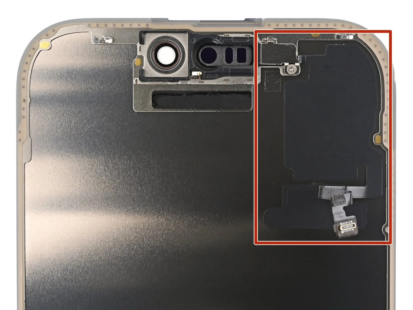
- The light level detection component resides beneath the display assembly, positioned adjacent to the openings intended for the Face ID sensor array.
- Determine whether the newly acquired display assembly incorporates a pre-installed ambient light sensor; if so, proceed to the designated link to bypass the subsequent twelve procedural instructions.
Step 21 | Remove the ambient light sensor bracket
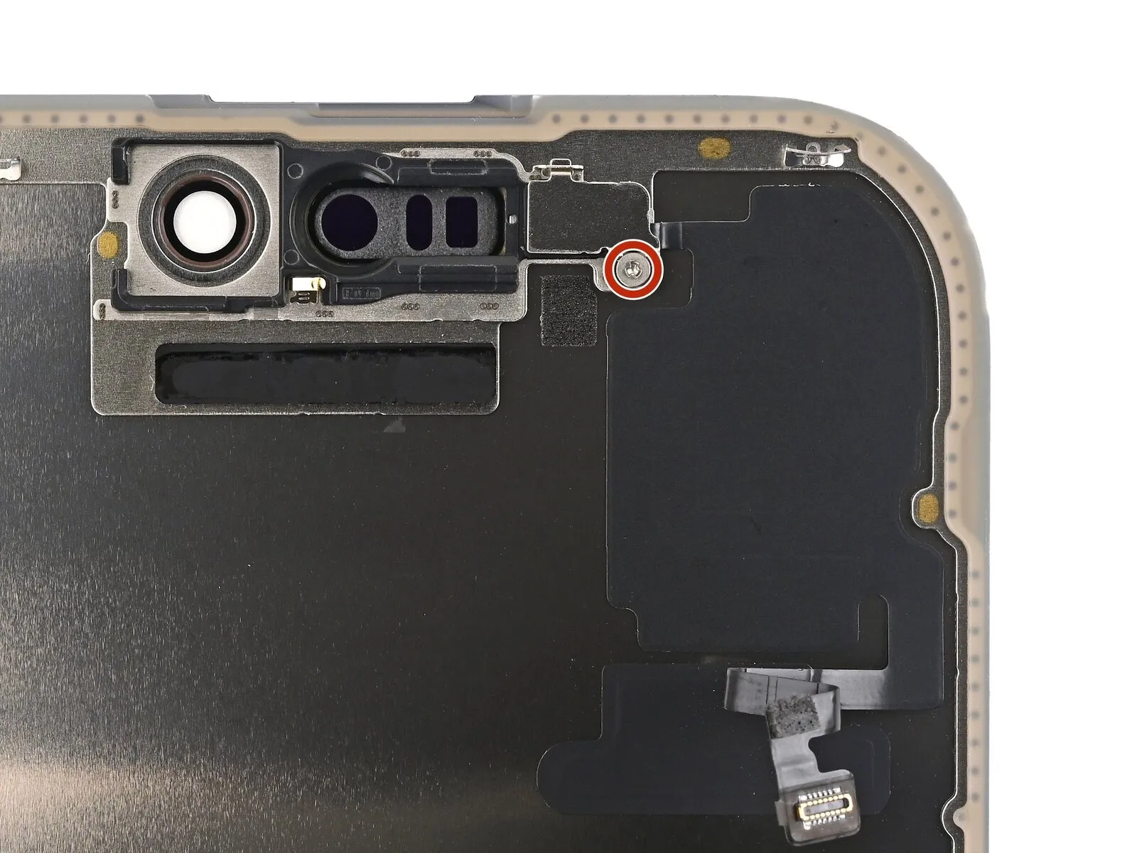
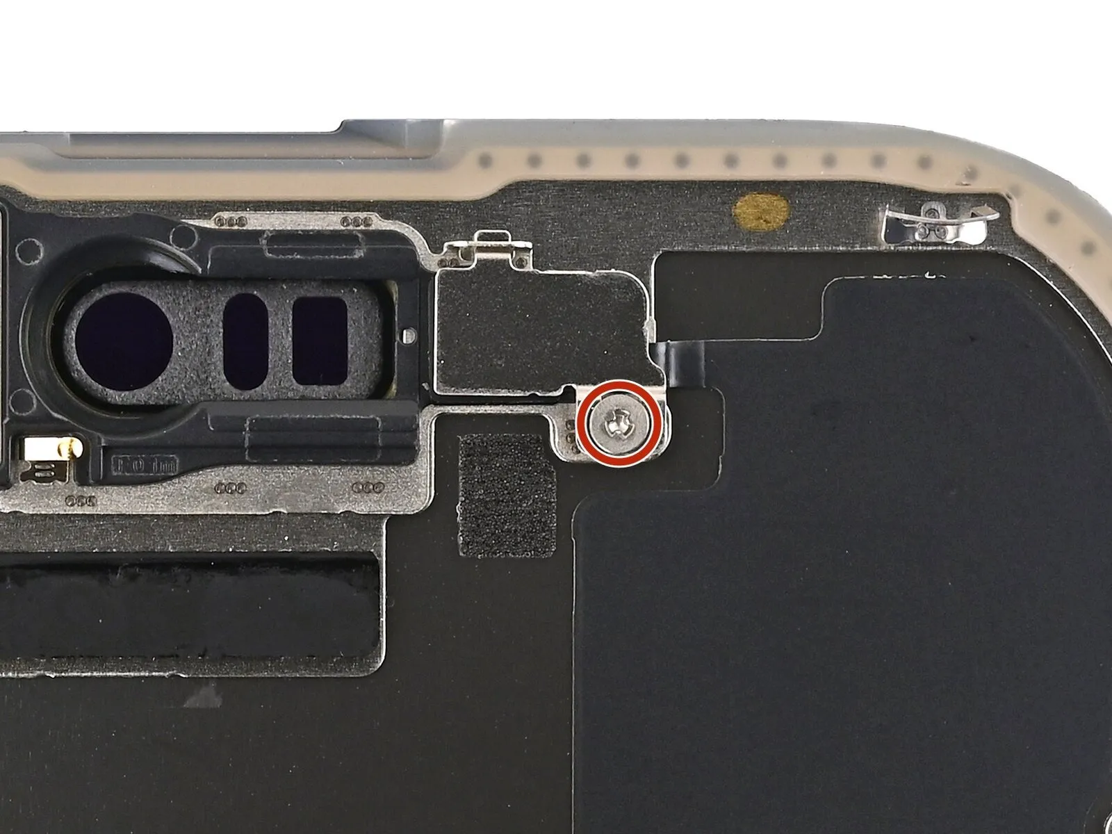
- Employ a Phillips screwdriver for the task of detaching the fastener.The screw, measuring 1 millimeter in length, requires a Phillips screwdriver for removal.A Phillips screwdriver is necessary to loosen and extract the screw.The bracket affixed to the ambient light sensor is held in place by a 1 mm screw.To release the bracket, utilize a Phillips screwdriver and unscrew the 1-millimeter fastener.
Step 22
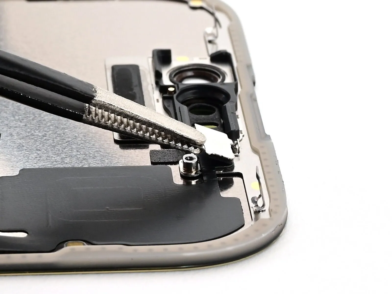
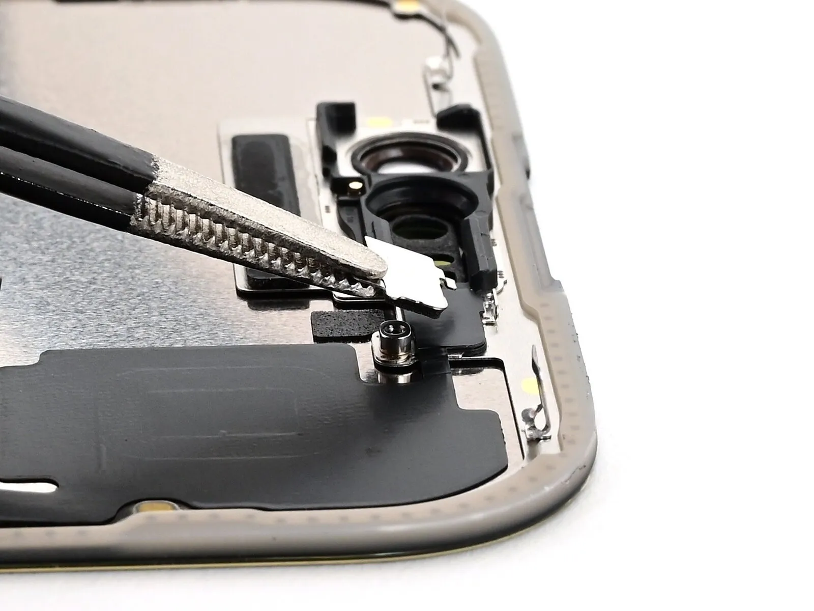
- Employ tweezers or your fingertips to detach and eliminate the bracket securing the ambient light sensor.
Step 23 | Heat the ambient light sensor cable

- Employing a hair dryer, heat gun, or iOpener will facilitate the loosening of adhesive securing the ambient light sensor and its associated cable.The application of heat using one of these tools will reduce the adhesive's bonding strength.Specifically, the targeted adhesive is located beneath the ambient light sensor.The ambient light sensor cable is also affixed by this adhesive and requires similar treatment.A hair dryer provides a gentler heat source, while a heat gun offers more concentrated warmth.An iOpener is a specialized tool designed for electronics repair, providing controlled heat application.Exercise caution when using heat to prevent damage to surrounding components.
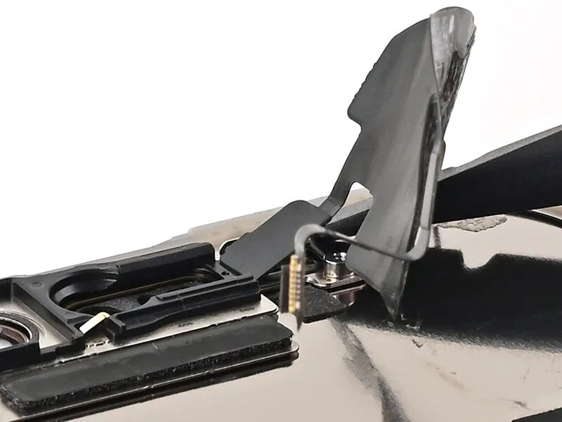
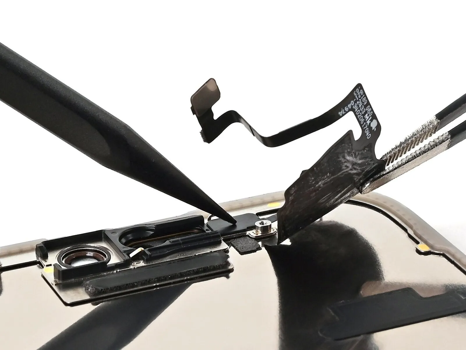
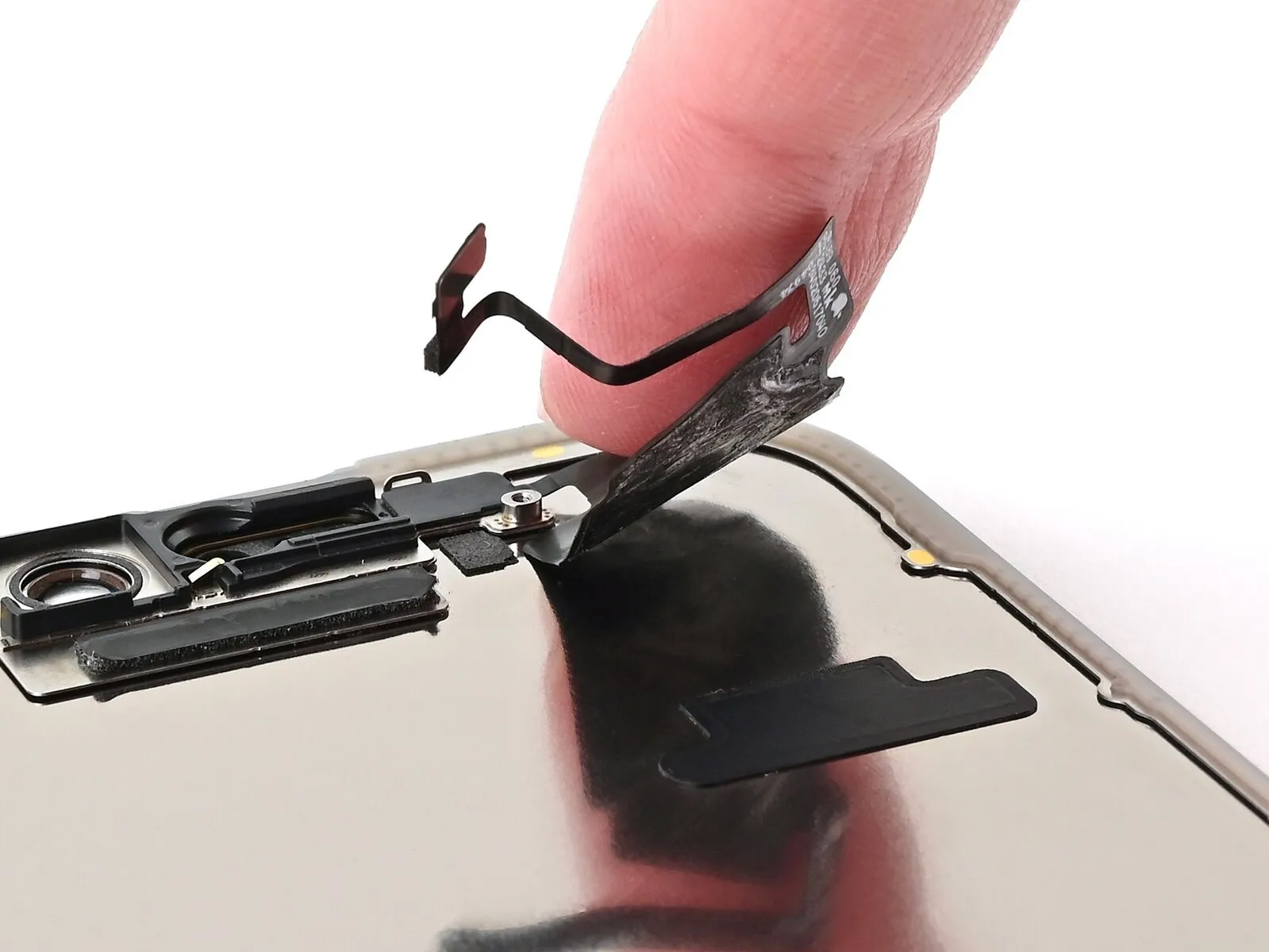
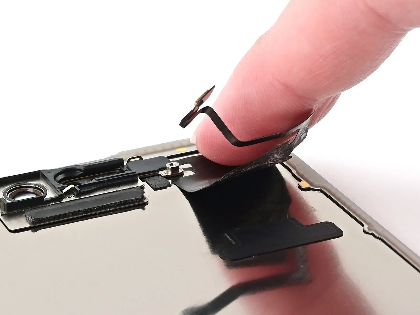
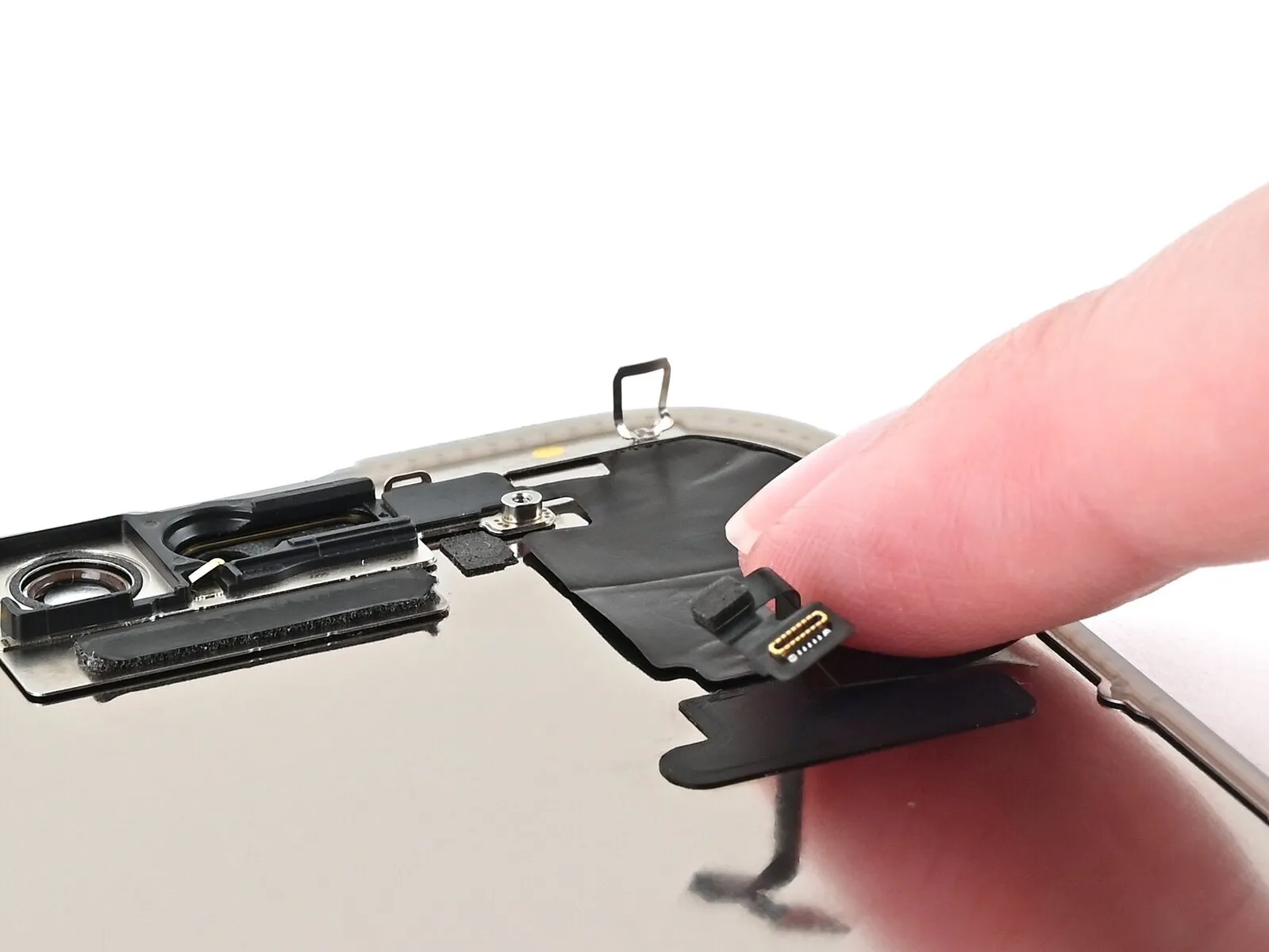
Step 24 | Peel up the ambient light sensor cable

- Exercise caution and proceed deliberately, as the cable possesses exceptional fragility, particularly in the vicinity of the sensor.Refrain from attempting to detach the sensor component at this juncture.
Commence sliding a specialized opening tool beneath the ambient light sensor cable, initiating the process beneath the connector at the lower edge and progressing upwards to disengage the cable from the display panel.
Should the adhesive layer resist separation, administer additional heat to facilitate its release.
Step 25 | Reheat the ambient light sensor
- Employ a hair dryer, heat gun, or iOpener device to reduce the viscosity of the adhesive securing the ambient light sensor.Applying heat with a hair dryer, heat gun, or iOpener will loosen the adhesive bond holding the ambient light sensor in place.
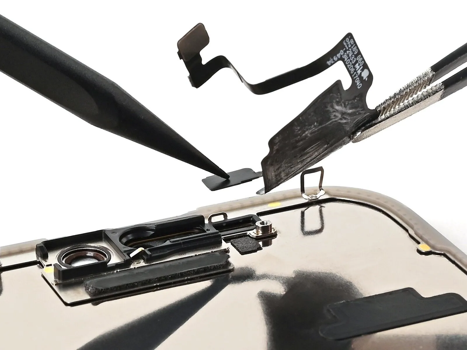
Step 26 | Pry up the ambient light sensor
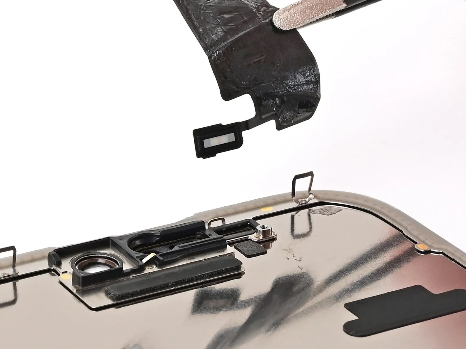
- Proceed deliberately to prevent damage to the delicate cable connected to the ambient light sensor.Should resistance be encountered, utilize increased heat rather than escalating the applied force.
- Employ the planar edge of a spudger for gradual separation of the ambient light sensor.Carefully lift the ambient light sensor from its position, focusing on the side where the cable is visible.
- Detach the ambient light sensor assembly completely.The ambient light sensor is now free from its mounting.
Step 27 | Prepare the ambient light sensor
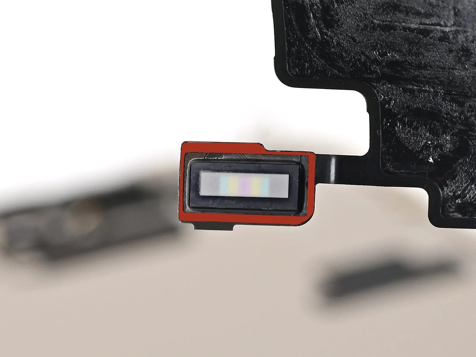
- Employ tweezers to carefully adjust any adhesive residue potentially obstructing the ambient light sensor during screen detachment.The repositioned adhesive ought to create a perimeter around the elevated rectangular shape.
- Should the adhesive become compromised or remain adhered to the discarded display assembly, substitute it with a 1-millimeter-wide segment of delicate, double-sided adhesive tape along its superior edge.This replacement tape should be applied to the top border.Ensure proper alignment to maintain sensor functionality.
Step 28 | Place the ambient light sensor
- Ensure the ambient light sensor is properly positioned within the screen's rear cavity.Employ a spudger tool or a fingertip to apply pressure.
- The sensor should be seated securely within its designated recess.This action guarantees correct alignment of the ambient light sensor.
Step 29 | Warm the ambient light sensor cable
- Employ a hair dryer, heat gun, or iOpener to reduce the adhesive bond securing the ambient light sensor and its associated cable.The adhesive requires only moderate warmth, avoiding excessive heat.Applying gentle heat facilitates separation without risking component damage.Ensure the temperature remains within a safe range to prevent melting or warping.Localized heat application is recommended for precise adhesive softening.Carefully monitor the temperature during this process to avoid overheating.The goal is to achieve sufficient flexibility in the adhesive for easy disconnection.
Step 30 | Press the ambient light sensor
- Apply direct pressure to the ambient light sensor cable using a fingertip.
Should the ambient light sensor cable fail to adhere properly, secure it with limited quantities of thin, double-sided adhesive material.A suitable adhesive for this purpose includes Tesa tape.Position the adhesive segments on the dorsal side of the sensor cable to ensure a secure bond.
Step 31 | Install the ambient light sensor bracket

- To secure the ambient light sensor bracket, position it over the sensor's rear surface and engage it using tweezers or manual manipulation.
Step 32
- Employ a Phillips screwdriver for the installation process.A 1 millimeter screw is required for this step.The screw's purpose is to fasten the bracket.This bracket is positioned on the ambient light sensor.Ensure proper alignment before tightening the fastener.
Step 33 | Remove the adhesive and its residue
- Employing a spudger or tweezers is necessary for dislodging adhesive remnants adhered to the iPhone's chassis.Careful maneuvering is essential to avoid damage to the delicate grounding clips located nearby.Should a grounding clip become displaced during this process, it can be carefully repositioned using your fingers or tweezers.The adhesive material securing components to the frame must be completely removed for successful disassembly.Grounding clips are susceptible to damage, so exercise caution to prevent unintended bending or breakage.
- Gentle manipulation is the preferred method for correcting any accidental displacement of the grounding clips.
Step 34
Step 35

- To prepare the frame and display surface for new adhesive application, meticulously wipe away residual adhesive using a non-abrasive cloth—a lint-free cloth or coffee filter will suffice—moistened with isopropyl alcohol possessing a concentration exceeding 90%.Achieve optimal cleaning by employing a unidirectional wiping motion with the cleaning cloth, rather than oscillating movements.Exercise caution to avoid displacement of the delicate grounding clips; should one become dislodged, carefully restore its original position using your fingers or a pair of tweezers.
- Prioritize meticulousness throughout this cleaning process, as it directly impacts the quality of the adhesive bond.
- A thoroughly cleaned frame facilitates the even distribution of replacement adhesive, which is essential for a secure and robust bond.
- Careful attention to detail during this step is critical, as it ensures the new adhesive adheres uniformly across the frame’s surface.
Step 36 | Apply the replacement adhesive

Position the adhesive sheet atop the frame's surface to establish the correct alignment.Employ existing frame characteristics, like the camera aperture, as visual references to assess the adhesive's placement.Proper orientation is ascertained by observing the adhesive sheet's relationship to the frame's design elements.
Visual confirmation of the adhesive's intended layout within the frame is achieved through careful observation of its features.
Step 37
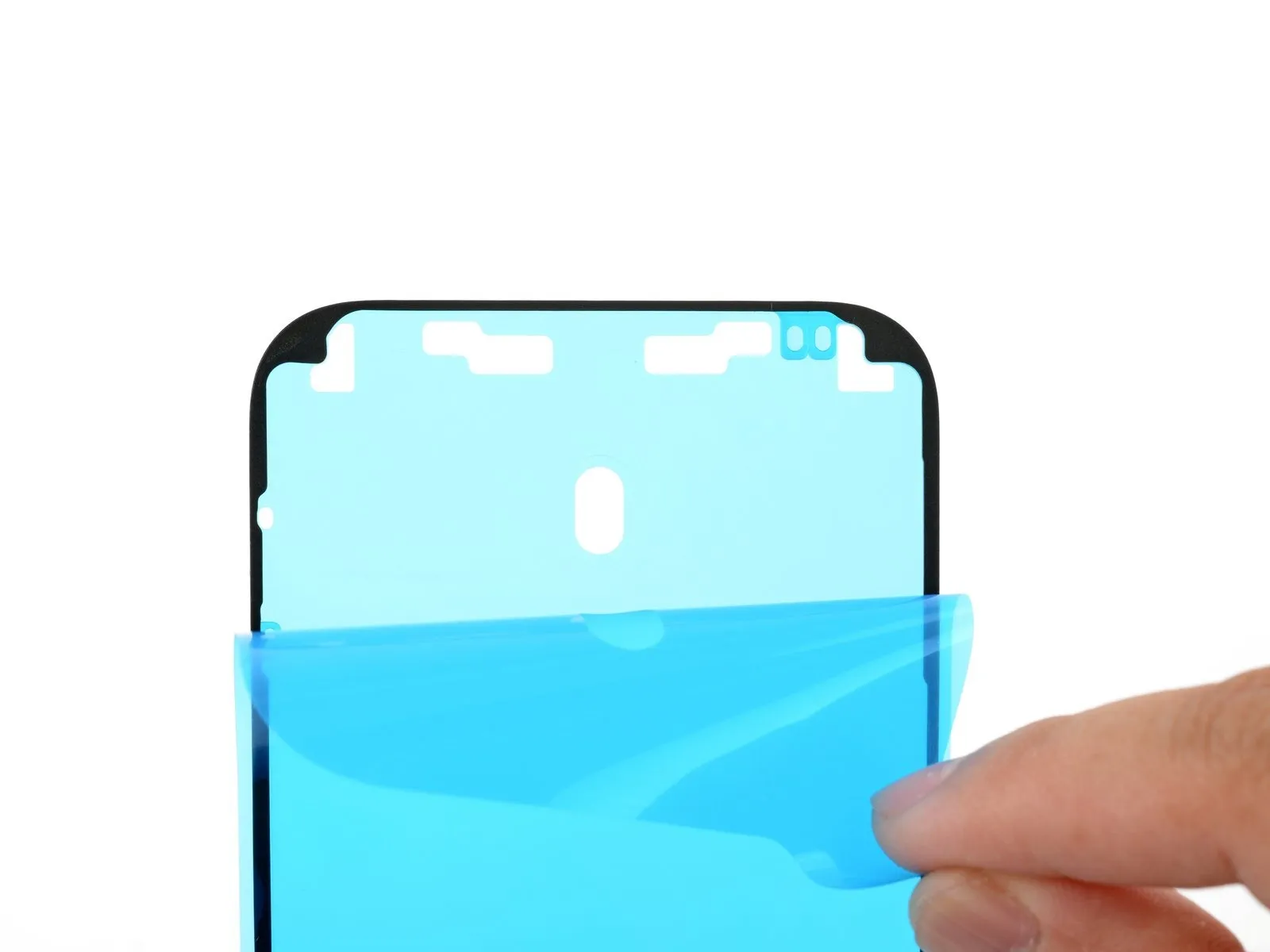
- Securely hold the corner tab of the adhesive sheet's liner.To reveal a portion of the adhesive, carefully remove the liner, exposing approximately one-third of its surface.
- Exercise caution, as the newly exposed adhesive possesses a high degree of tackiness; prevent unintended contact with other surfaces until application.
- For adhesive products featuring multiple liners, remove only the uppermost liner to reveal the side intended for frame adhesion.
Step 38
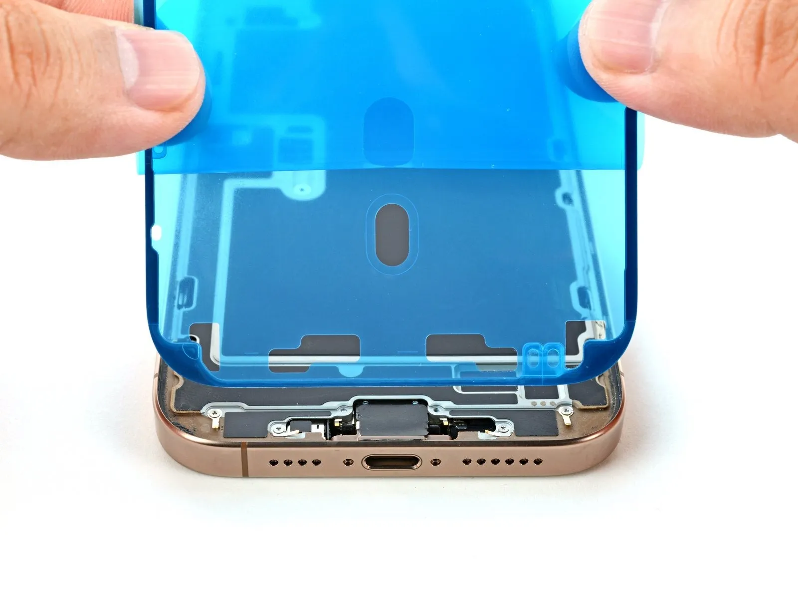
- Ensure the visible perimeter of the adhesive strip is precisely matched to the bordering edge of the iPhone's frame.Following application of the adhesive, repositioning is impossible; any misalignment necessitates removal and replacement with a fresh adhesive strip.Correct alignment is crucial before applying pressure, as adjustments are not possible after the adhesive bonds.
- Apply even pressure to secure the adhesive strip to the frame, ensuring a firm bond along its entire length.
- The adhesive strip, once affixed, cannot be adjusted, requiring meticulous positioning before permanent attachment.
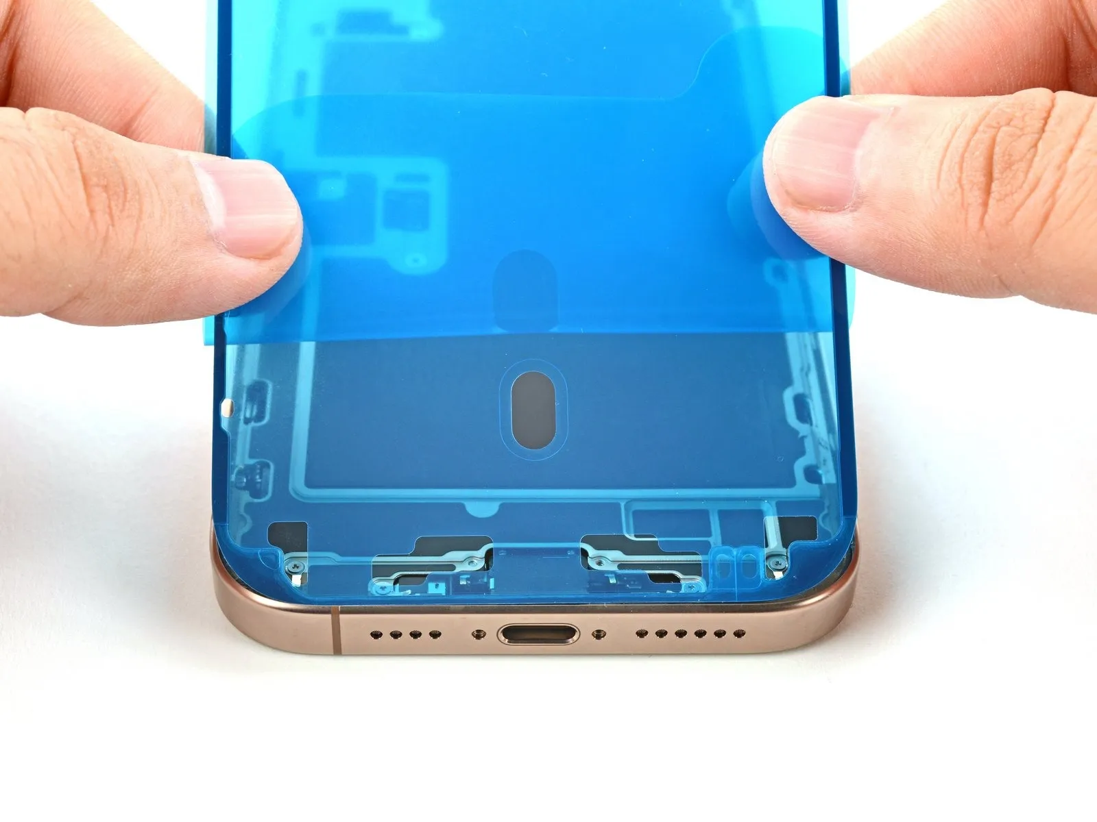
Step 39

- Carefully remove the adhesive backing, ensuring firm contact between the adhesive and the surface.
- Proper alignment of the adhesive is indicated by a seamless fit of the edges.
- To correct minor positioning errors, reposition the adhesive by pulling the extended borders toward the frame.
- Should the adhesive develop folds or distortions, discard it and apply a new strip.
- In the absence of replacement adhesive, the iPhone can be reassembled and used without it; however, be aware that its water resistance will be diminished until a replacement is installed.
Step 40
- Employ a spudger to apply pressure to the adhesive sealant that secures the iPhone's perimeter.Exercise caution to avoid damaging the delicate grounding clips during this process; if displacement occurs, carefully reposition them using your fingers or tweezers.Excessive force should be avoided to prevent distortion or over-extension of the adhesive material.
- The adhesive's integrity is maintained by distributing pressure evenly around the device's edges with the spudger.
- Grounding clips are susceptible to damage from undue pressure, requiring careful manipulation to restore their original position.
Step 41

- Employ a spudger tool, or manually use your fingers, to detach the pull tab affixed to the extensive front liner, typically found in a corner.Utilize the detached pull tab to carefully separate the large front liner from its adhesive backing.Remaining protective liners may still cover the device's edges, safeguarding the adhesive during reassembly; refrain from removing these smaller release liners at this stage.
- These smaller liners serve to prevent unintended adhesion during the reassembly process.
- The purpose of these remaining liners is to ensure the adhesive does not adhere to unintended surfaces while you are reassembling the iPhone.
Step 42 | Reconnect the screen

- Apply finger pressure to secure the display connector's connection.
- For reattaching wide press connectors, meticulously position and depress one edge until a distinct click is heard, then repeat the process on the opposing edge; avoid central pressure, as misalignment can result in pin bending and irreversible damage.
- Establish a connection for the front sensor connector by applying downward pressure.
- Carefully position the connector above its corresponding socket and apply pressure with a fingertip until a click confirms proper engagement; refrain from forceful insertion, and reposition if necessary.
- Now is an opportune moment to activate your iPhone and verify all functionalities prior to final enclosure, ensuring a complete power-down afterward.
- Should your iPhone fail to power on, connect it to an external power source and attempt the startup sequence once more.
Step 43 | Install the connector covers
- Secure the display connector cover by inserting its tab into the corresponding opening within the frame, then position the cover correctly.
- Perform the same procedure for the front sensor connector cover to ensure its proper placement.
Step 44

- Employ a specialized tri-point Y000 driver for the installation process.The screws, each measuring 1.3 millimeters in length, require a tri-point Y000 driver for proper engagement.Two connector covers are affixed with fasteners necessitating a tri-point Y000 driver for removal and reinstallation.A tri-point Y000 driver is essential for manipulating the fasteners that hold the connector covers in place.To properly secure the two connector covers, utilize a tri-point Y000 driver and the provided 1.3 mm screws.
Step 45 | Remove the final liners
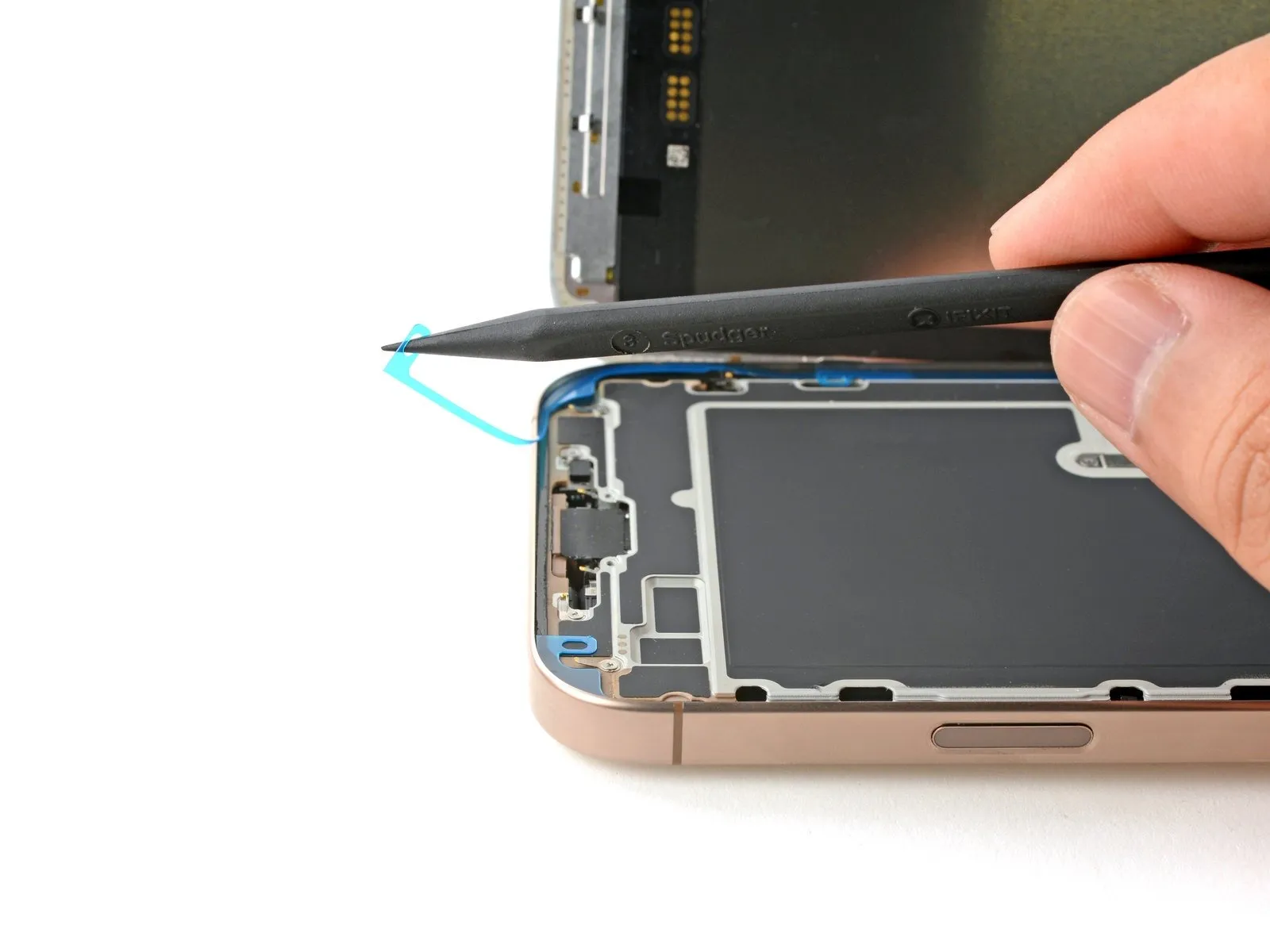
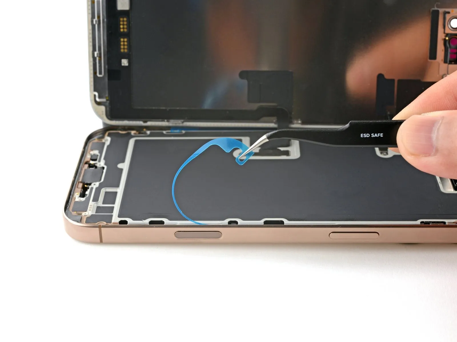
- Maintain stability of the display assembly with your hand or a specialized prying tool to detach the adhesive-secured perimeter liners, revealing the bonding agent.Employing caution, avoid direct contact with the newly exposed adhesive to prevent contamination or diminished adhesion.Thoroughly inspect the device's frame and display surface for any detached liner fragments and eliminate them.
- Ensure complete removal of all liners; the absence of any liners is essential for proper reassembly and sealing.
- Utilize a non-conductive tool, such as a spudger, to carefully separate the liners from the device's surface.
Step 46 | Install the screen onto the frame
Step 47


- Position the display assembly against the chassis, initiating the alignment from the uppermost boundary.
- Should you encounter opposition during the placement, a surrounding retaining clip might be deformed and compressed by the frame; carefully examine the area of obstruction and delicately restore any clips to their original shape.
- Verify that the screen's periphery isn't exerting pressure on any connecting wires.
Step 48 | Apply heat to the perimeter

- Apply warmth around the screen's edges utilizing a hair dryer, heat gun, or iOpener, ensuring the surface reaches a temperature just beyond comfortable touch.
- This thermal application reduces the adhesive's viscosity, facilitating a more secure reattachment.
Step 49 | Apply pressure to the perimeter


Employ your fingertips to apply consistent, secure pressure encompassing the entire circumference of the iPhone's housing.
Step 50


- Position the iPhone with the screen facing downwards onto a pristine, level workspace.
- Apply a continuous strip of adhesive tape along the outer edge of the rear glass to safeguard its cosmetic appearance.
- Arrange a circular stack of coins bordering the rear glass, constructing a barrier that matches the height of the rear camera lenses' extensions.
- As an alternative method, secure vise clamps around the device's edges to establish proper adhesion.
Step 51


- To apply even pressure, position four to five substantial volumes directly atop the iPhone's surface.
- Because the weight could potentially create minor marks on the book covers, avoid utilizing valuable or delicate materials.
- Maintain the applied pressure by keeping the books in their position for approximately half an hour.
- This sustained force facilitates the bonding process of the adhesive material.
Step 52 | Install the pentalobe screws
Employ a P2 pentalobe screwdriver for the installation process.The required tool is a P2 pentalobe screwdriver.Two screws, each measuring 7.4 millimeters in length, must be affixed.Secure the two 7.4 mm screws to the device's chassis.Position the screws on both sides of the USB-C port using the appropriate screwdriver.