iPhone 16 Pro Chip ID
Images of the printed circuit board were captured with a United States-market iPhone 16 Pro.
- This particular iPhone 16 Pro variant does not incorporate a physical SIM card slot, yet retains internal components enabling 5G millimeter wave connectivity and satellite communication capabilities.Further technical specifications can be found in our comprehensive iPhone 16 Pro disassembly guide.
- We extend our gratitude to community participant Chunglin Chinfor their valuable contribution to this repair documentation.
Step 1 | Logic board overview
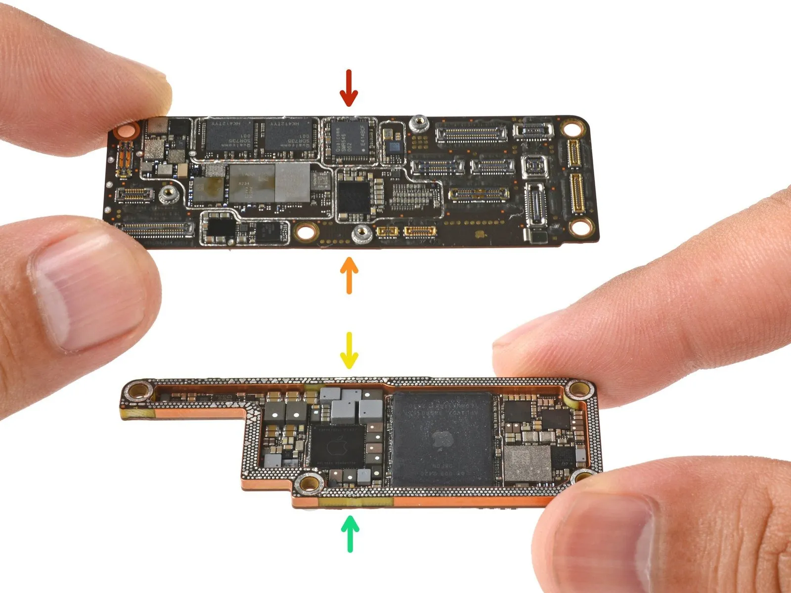
The iPhone 16 Pro's internal circuitry utilizes a pair of double-sided printed circuit boards (PCBs) to manage its functions.
- The upper portion of the radio frequency (RF) board is one of these PCBs.
- The lower portion of the radio frequency (RF) board constitutes the second of these PCBs.
- The primary functions are handled by a PCB designated as the main board's upper section.
- The main board's lower section represents the final PCB within the iPhone 16 Pro's logic board assembly.
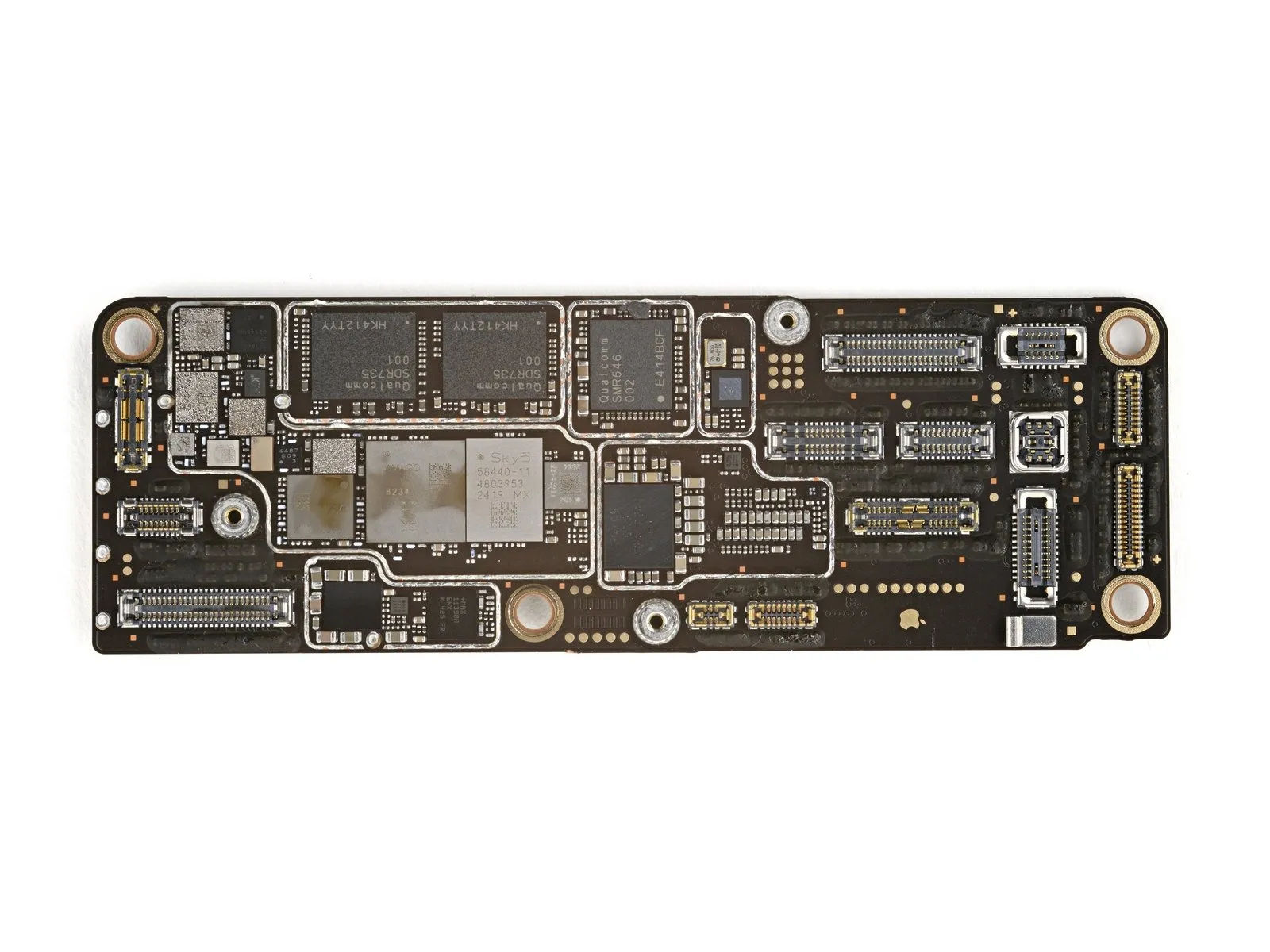
Step 2 | RF Board Top
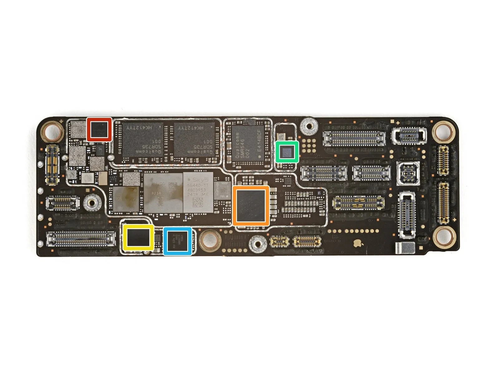
- The STMicroelectronics ST33J provides embedded SIM and secure element functionality.
- Power management capabilities are delivered by the Qualcomm PMX65-000 component.
- Audio amplification is achieved through the Cirrus Logic 338S01087.
- A Qualcomm component is responsible for generating timing signals within the device.
- The Analog Devices MAX11390A converts analog signals into digital data.
Step 3 | RF Board Top - Connectivity
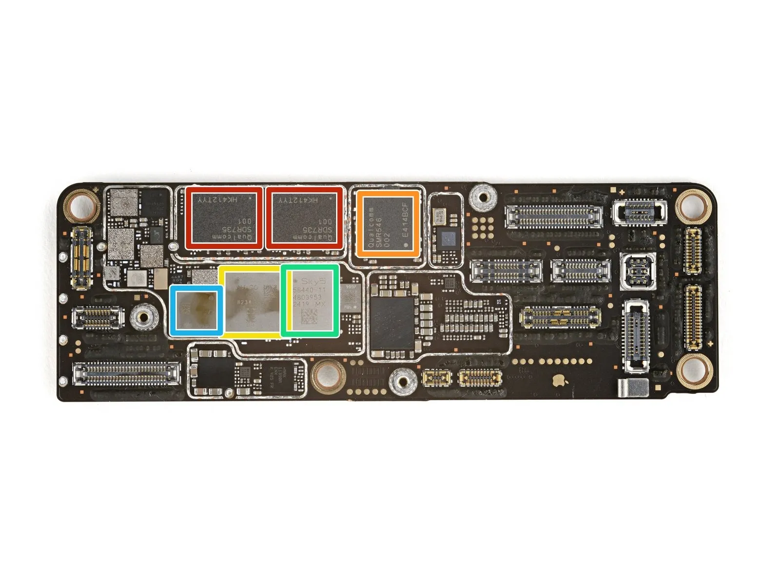
- The Qualcomm SDR735-001 serves as a radio frequency transceiver.
- Intermediate frequency communication is facilitated by the Qualcomm SMR546-002 transceiver.
- A Broadcom AFEM-8234 module manages the device's front-end operations.
- The Skyworks SKY58440-11 component provides front-end functionality.
- Qorvo's QM76307 module also contributes to the device's front-end design.
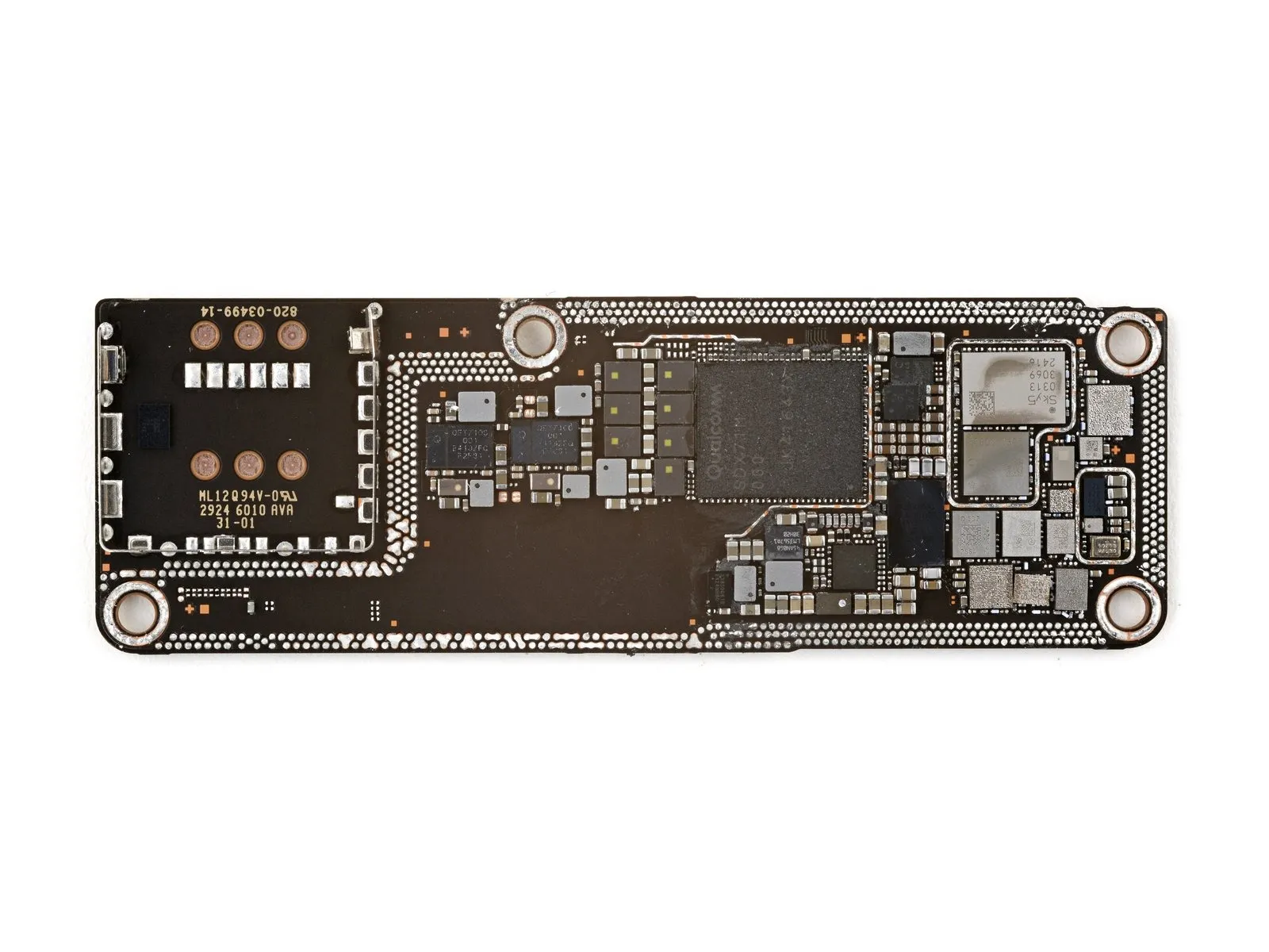
Step 4 | RF Board Bottom
- The Texas Instruments LM3567A1 manages the operation of an LED flash.
- Wireless charging functionality is controlled by the Broadcom BCM59367A1.
- A wideband envelope tracking system is implemented using the Qualcomm QET7100-001.
- Power for the envelope tracker is supplied by a Qorvo power supply.
- The Apple 338S00616 provides direct current-to-direct current voltage conversion.
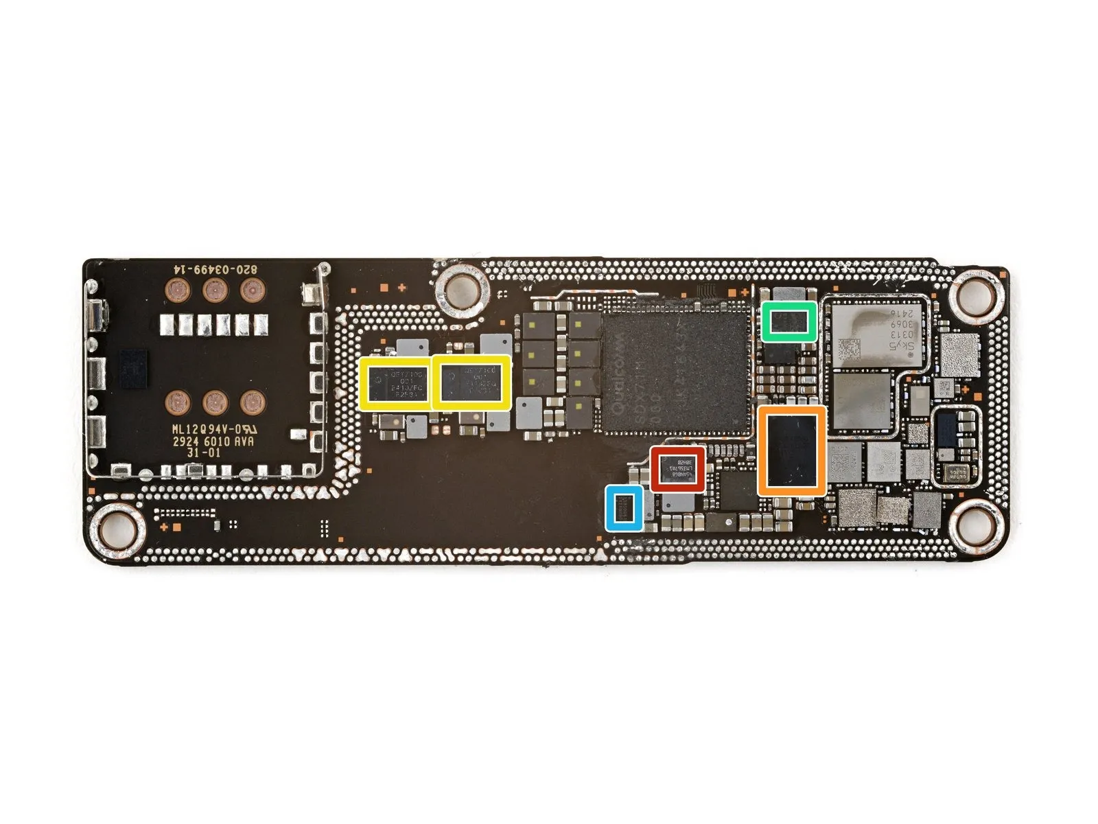
Step 5 | RF Board Bottom - Connectivity
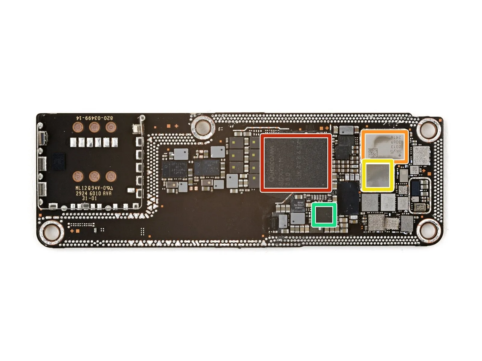
- The device incorporates a Qualcomm SDX71M-000 modem for cellular connectivity.
- A Skyworks component serves as the radio frequency front-end module.
- The front-end functionality is further supported by a Qorvo QM76306 module.
- Near-field communication capabilities may be managed by an NXP Semiconductors NFC controller.
Step 6 | Main Board Top
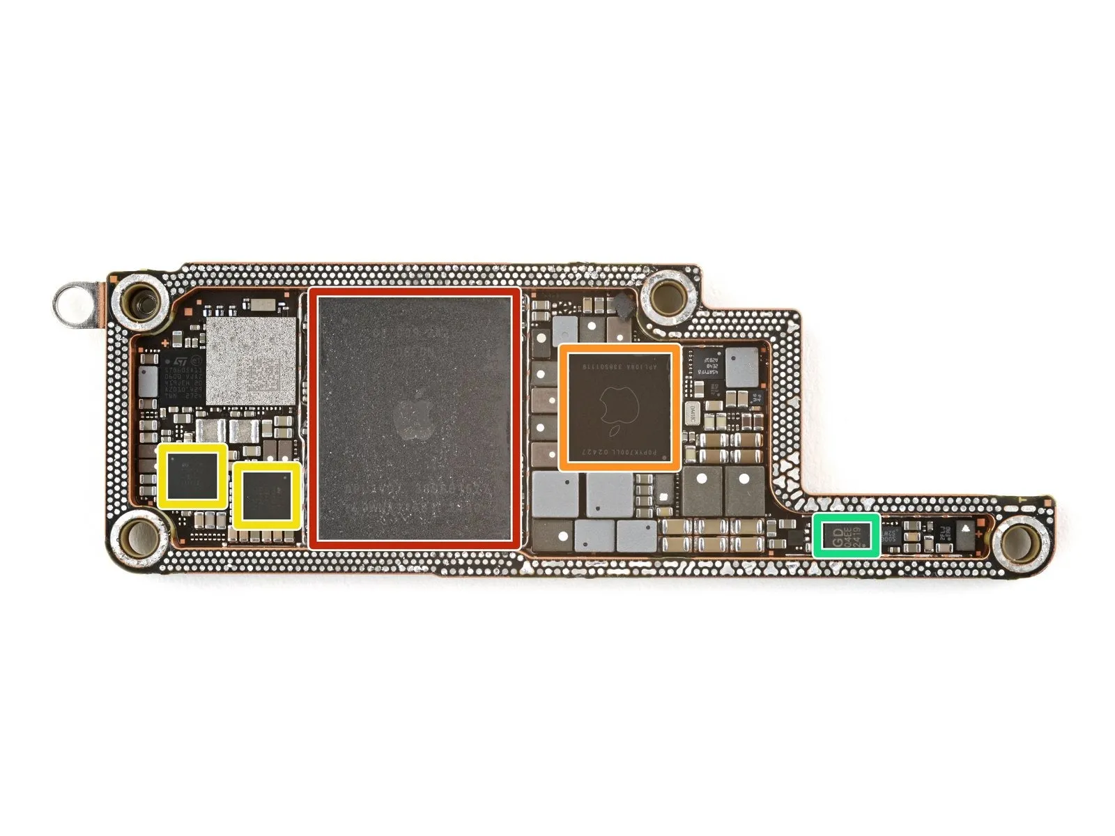

- The Micron MT62F1G64D4AQ-031 XT:C, a LPDDR5X SDRAM memory module, is integrated with the Apple APL1V07 / 339S01527 A18 Pro processor, which incorporates a graphics processing unit (GPU) and a neural engine, utilizing a hexa-core architecture.
- The Apple APL109A / 338S01119 component handles power distribution within the device.
- Power management functionality is also provided by the STMicroelectronics STPMIA3C.
- A 1 MB serial NOR flash memory chip, specifically the GigaDevice GD25Q80E, is present for data storage.
Step 7 | Main Board Top - Connectivity

- The USI 339M00326 represents a module utilizing ultra-wideband (UWB) radio technology.
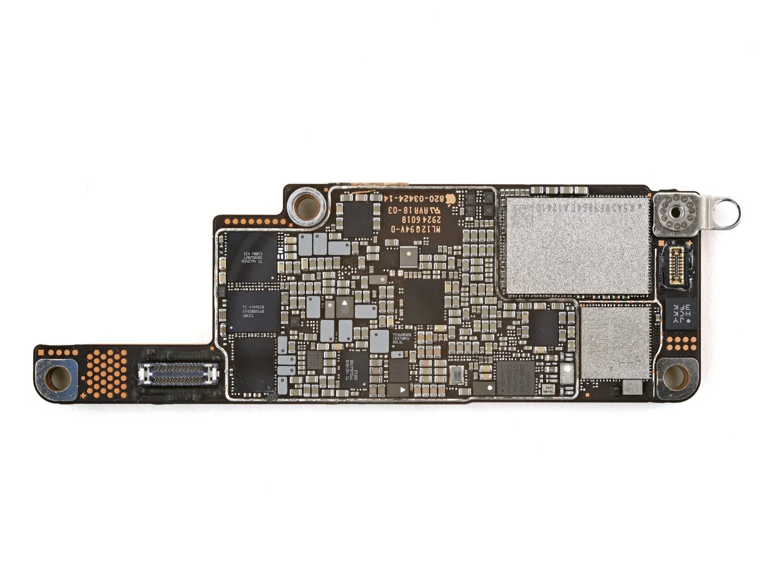
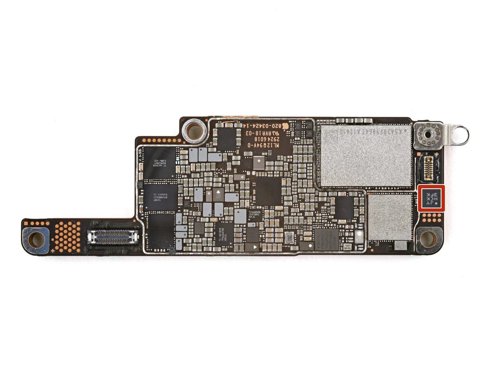
Step 8 | Main Board Bottom
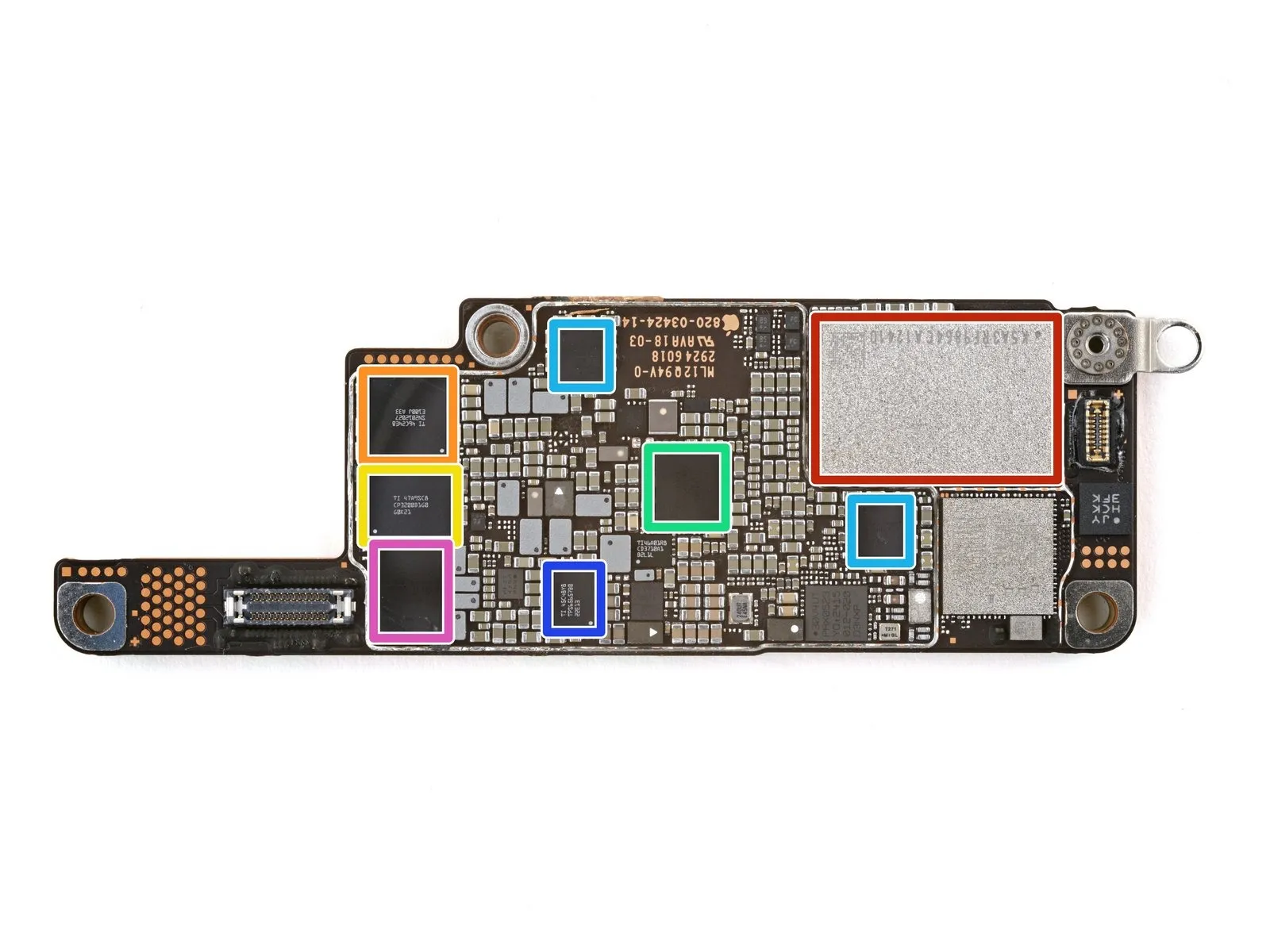
- The device incorporates a Kioxia K5A3RF9864 NAND flash memory chip with a storage capacity of 128 GB.
- A probable component is the Texas Instruments SN2012027, which functions as a USB Type-C controller.Powering the battery is a Texas Instruments CP3200B1G0 integrated charger circuit.
- Audio processing is handled by the Cirrus Logic 338S00967 audio codec.Sound amplification is provided by the Cirrus Logic 338S01087 audio amplifier.
- The display receives power through the Texas Instruments TPS65657B0 power supply IC.
- The presence of this component is highly probable.
- The Cirrus Logic 338S00843 manages power distribution within the system.
- The NAND flash memory chip is identified as a Kioxia K5A3RF9864 with a 128 GB capacity.The USB Type-C functionality is facilitated by the Texas Instruments SN2012027 controller.
Step 9
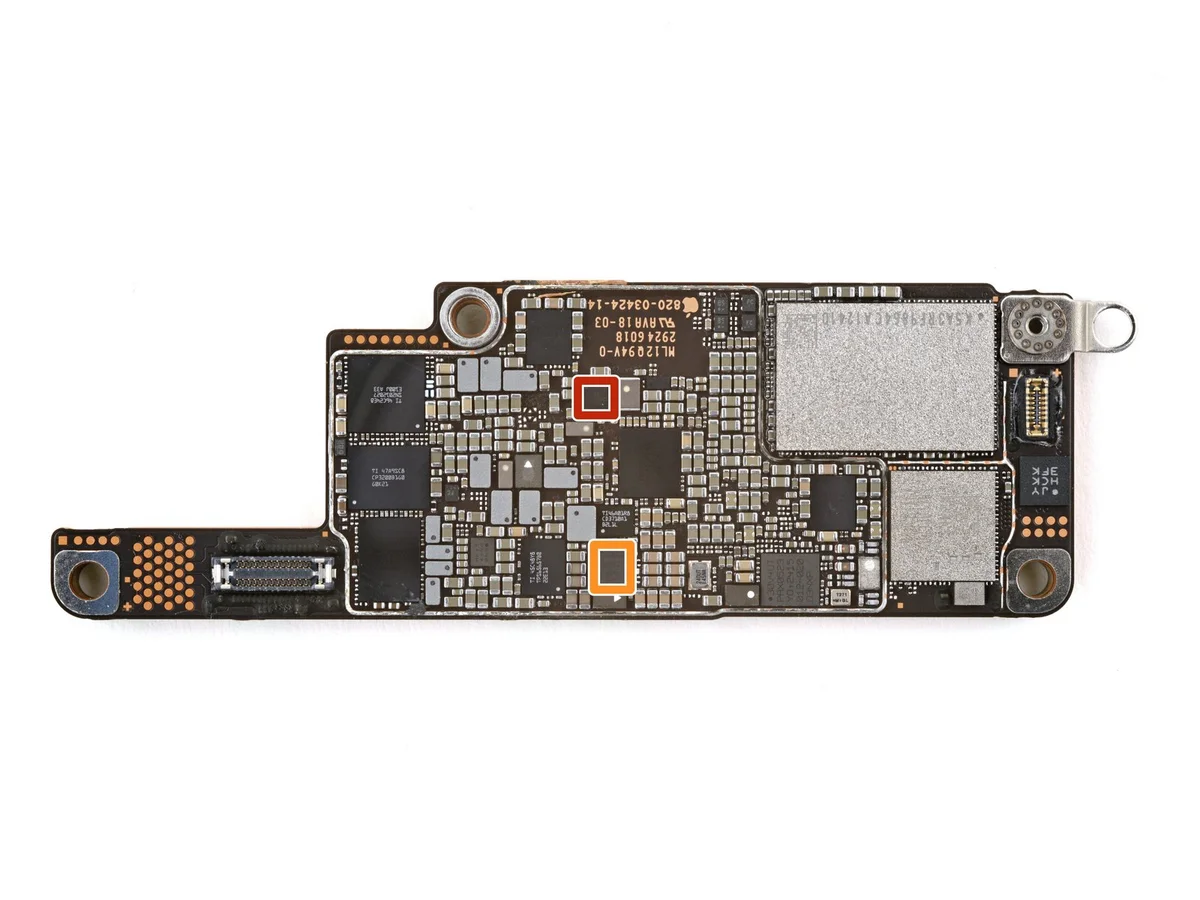
- The integrated circuit originates from Texas Instruments.This component is identified as the TPS61280H.It functions as a battery front-end DC-DC converter.
- Apple utilizes this device in their product designs.The specific part number assigned by Apple is 338S01026-B1.Its primary role is within the overall power management system.
Step 10 | Main Board Bottom - Connectivity
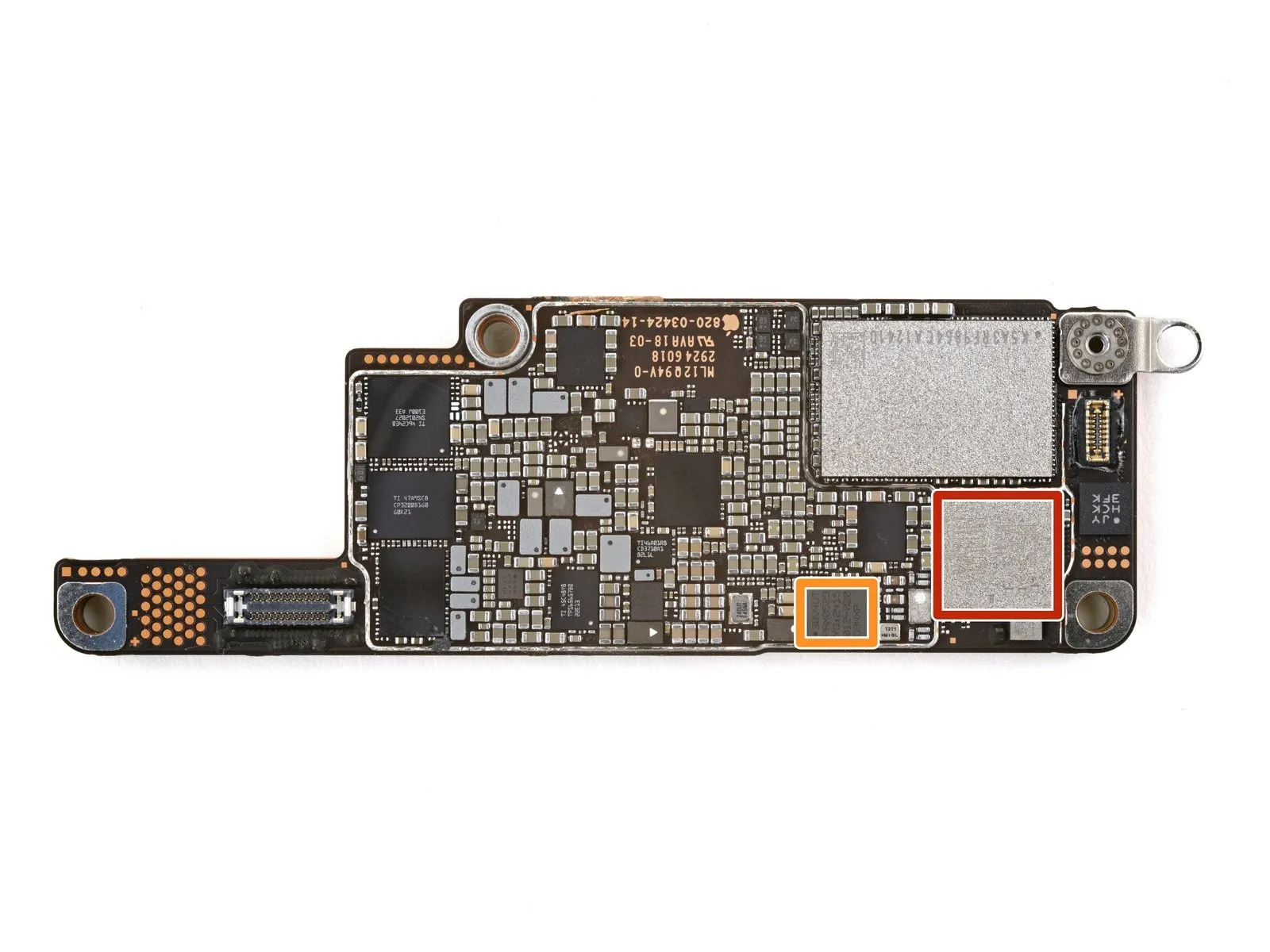
- The component originates from USI, identified by the part number 339S01464.This module integrates Bluetooth and WiFi communication capabilities.NXP Semiconductors manufactures the described module.
- The integrated circuit also incorporates a Near Field Communication (NFC) controller.Refer to the manufacturer's documentation for detailed specifications regarding this integrated module.
Step 11 | Main Board Bottom - Sensors
The Bosch Sensortec accelerometer and gyroscope are components utilized for motion sensing.