iPhone 15 Plus Microphone Replacement
Use this guide to replace the microphone in your iPhone 15 Plus.
If your iPhone's having a hard time picking up your voice, or has intermittent issues, the microphone might need to be replaced. The microphone in this guide is the primary of three microphones, and can be replaced as a single unit. Another microphone is integrated with the charging port assembly, and a third is integrated with the power button assembly.
- You'll need replacement back glass adhesive to complete this repair.
Step 1 | Prepare your phone for disassembly


- Allow your phone's battery to drain below 25%. A charged lithium-ion battery can be a safety hazard.
- Unplug any cables from your phone.
- Hold the power and either volume buttons, then slide to power off your phone.
Step 2 | Tape over any cracks


- If your screen or back glass is badly cracked, lay overlapping strips of packing tape over the glass to protect yourself and make disassembly easier.
- Make sure there's a smooth area near the bottom edge that's big enough for a suction cup to stick to.
Step 3 | Mark your opening picks


- If inserted too far, an opening pick can damage your device. Follow this step to mark your pick and prevent damage.
- Measure 3 mm from the tip and mark the opening pick with a permanent marker.
- You can also mark the other corners of the pick with different measurements.
- Alternatively, tape a coin to a pick 3 mm from the tip.
Step 4 | Remove the pentalobe screws
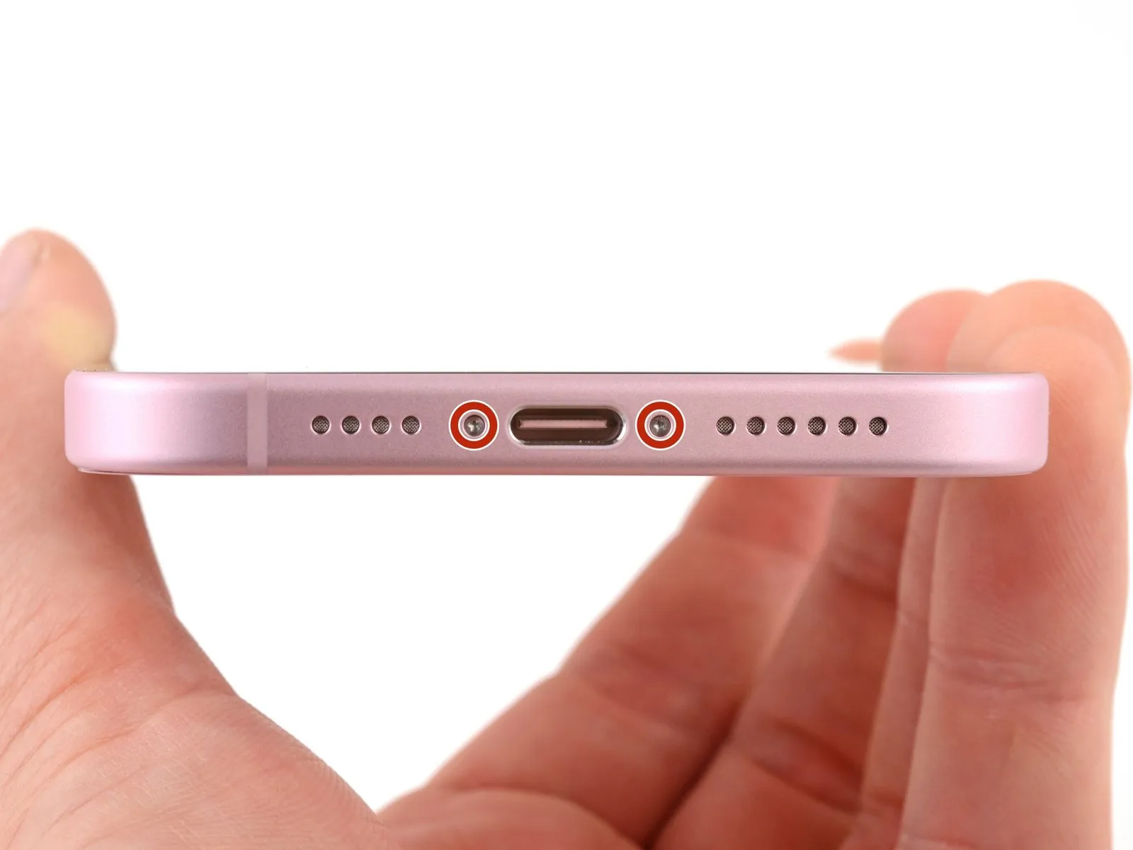
Use a P2 pentalobe driver to remove the two 7.7 mm-long screws on either side of the charging port.
Step 5 | Heat the bottom edge
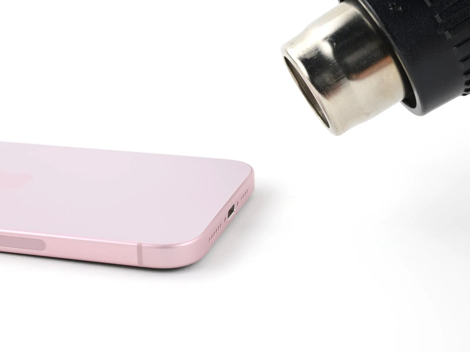
- Use a hair dryer or heat gun to heat the bottom edge of the back glass until it's hot to the touch.
- Be careful not to heat the phone hotter than this—the battery is susceptible to heat damage.
Step 6 | Insert an opening pick
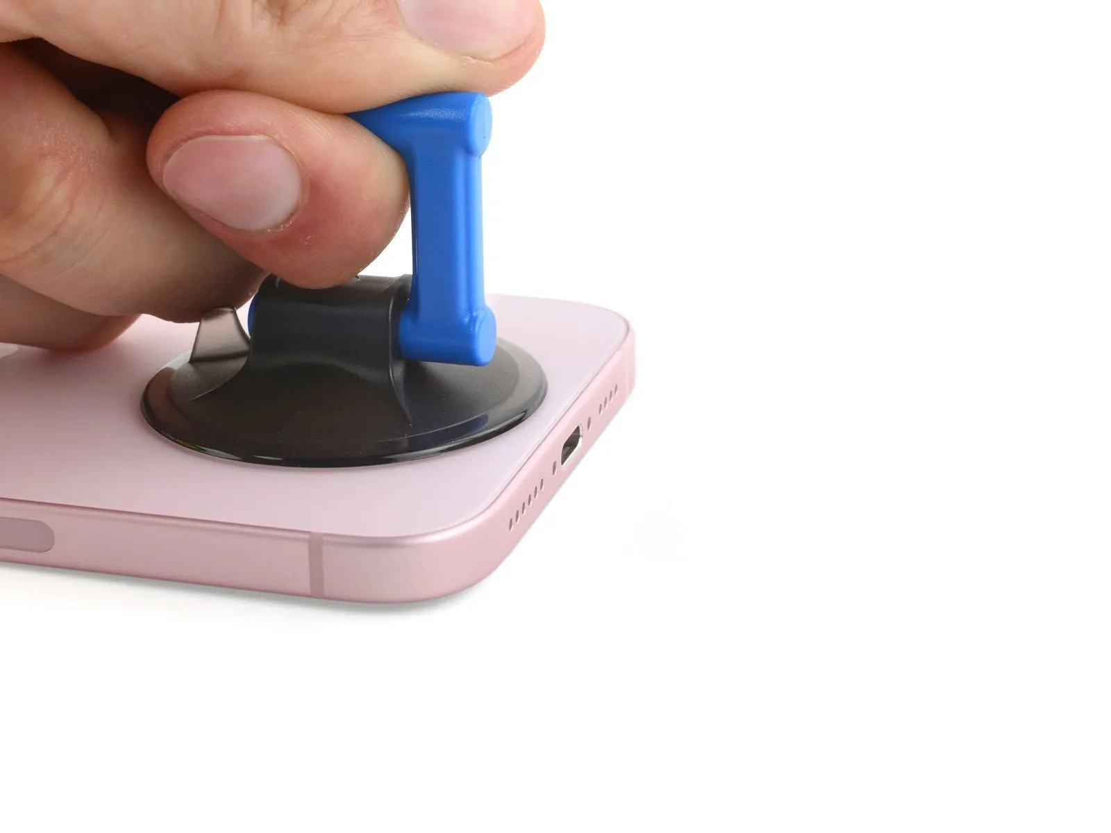

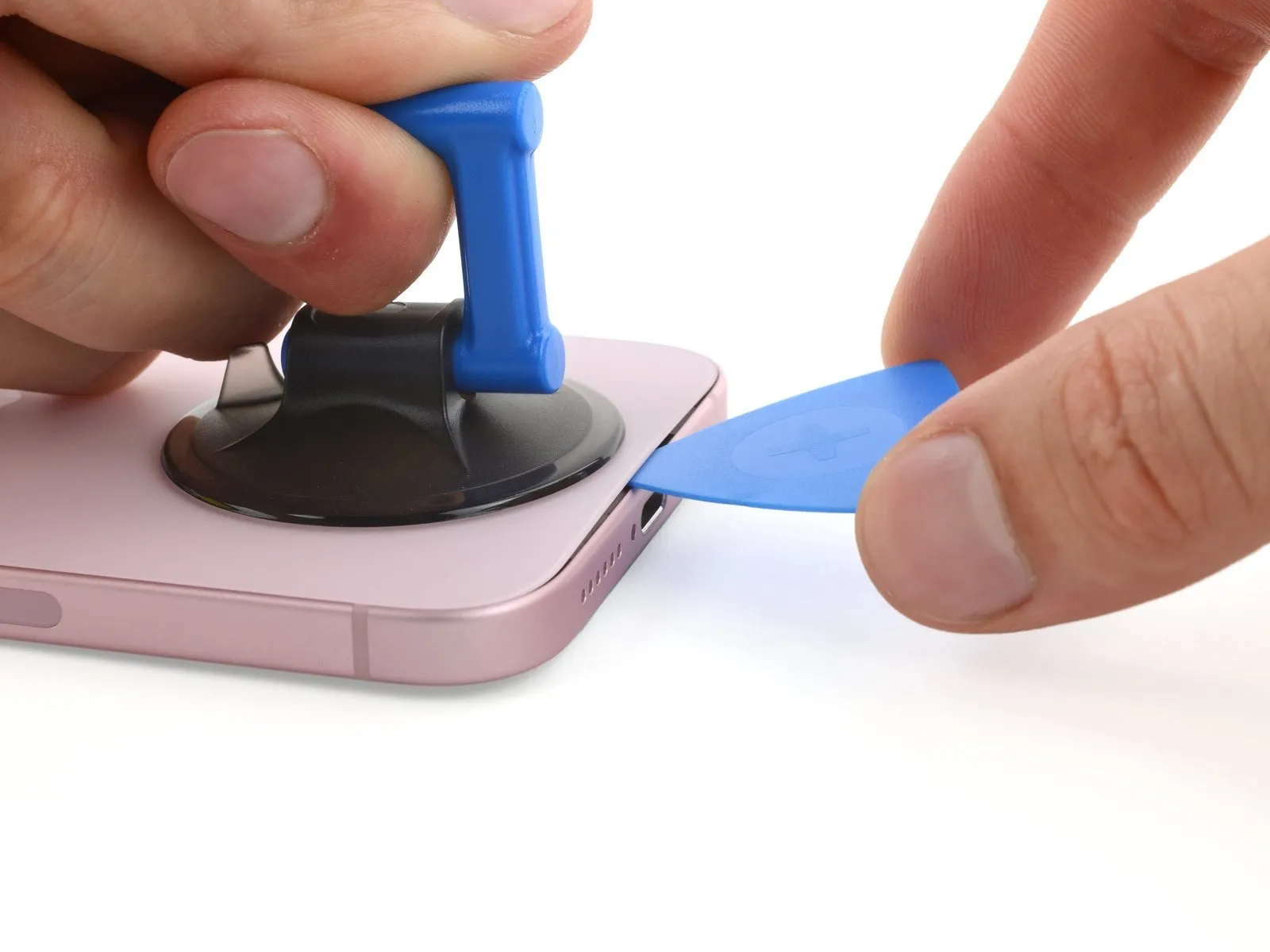
- Apply a suction handle to the bottom edge of the back glass.
- Pull up on the handle with a strong, steady force to create a gap between the back glass and the frame.
- Insert the tip of an opening pick into the gap.
Step 7 | Back glass information
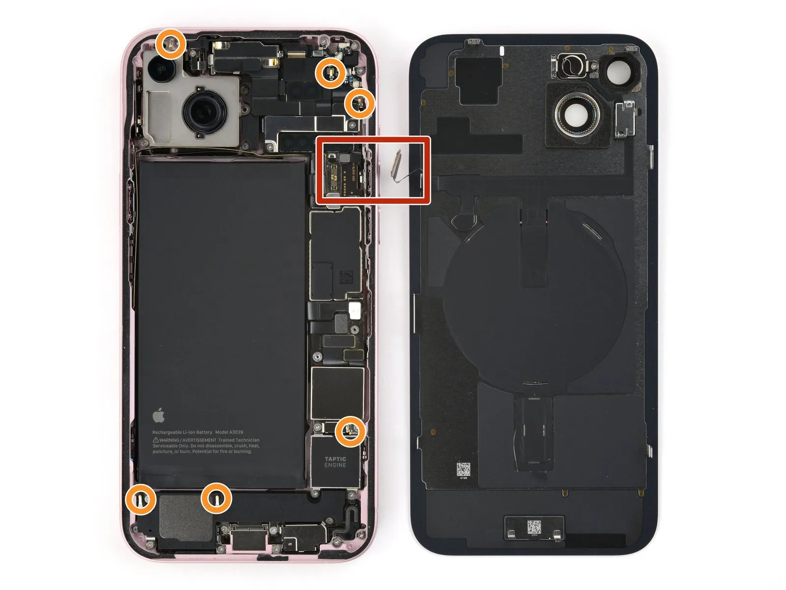
- As you slice the adhesive securing the back glass in the next steps, be careful of the following areas:
- A delicate cable connecting the back glass to the phone is right next to the volume up button. Don't insert your pick here to avoid slicing the cable.
- Multiple spring contacts are around the perimeter of the phone. Be extra careful not to insert your pick deeper than suggested in each step to avoid bending these contacts.
Step 8 | Separate the bottom edge adhesive
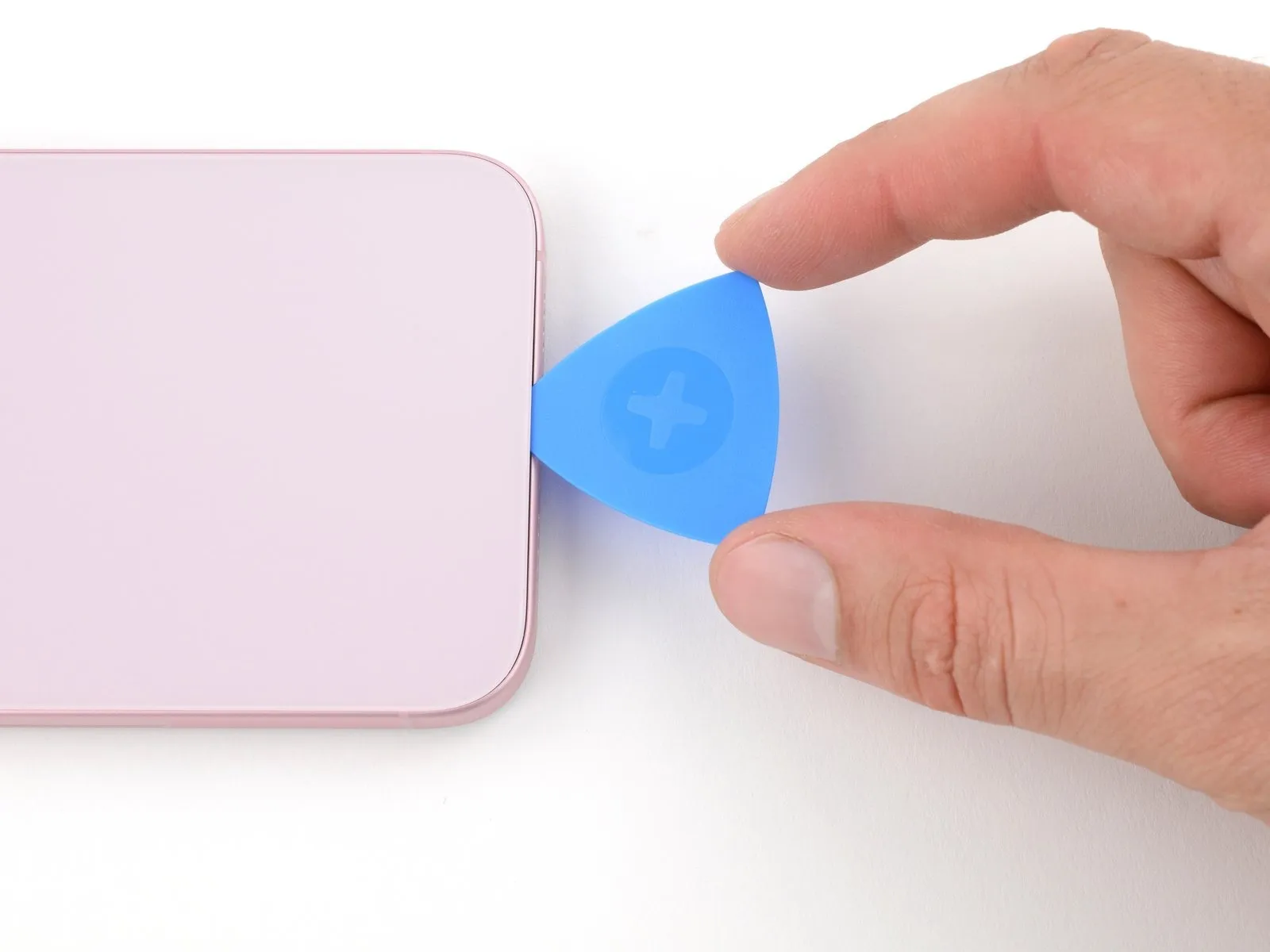


- Don't insert your opening pick deeper than 5 mm along the bottom edge.
- Slide your pick back and forth along the bottom edge to separate the adhesive.
- Leave your pick inserted in the bottom right corner to prevent the adhesive from re-sealing.
Step 9 | Heat the right edge
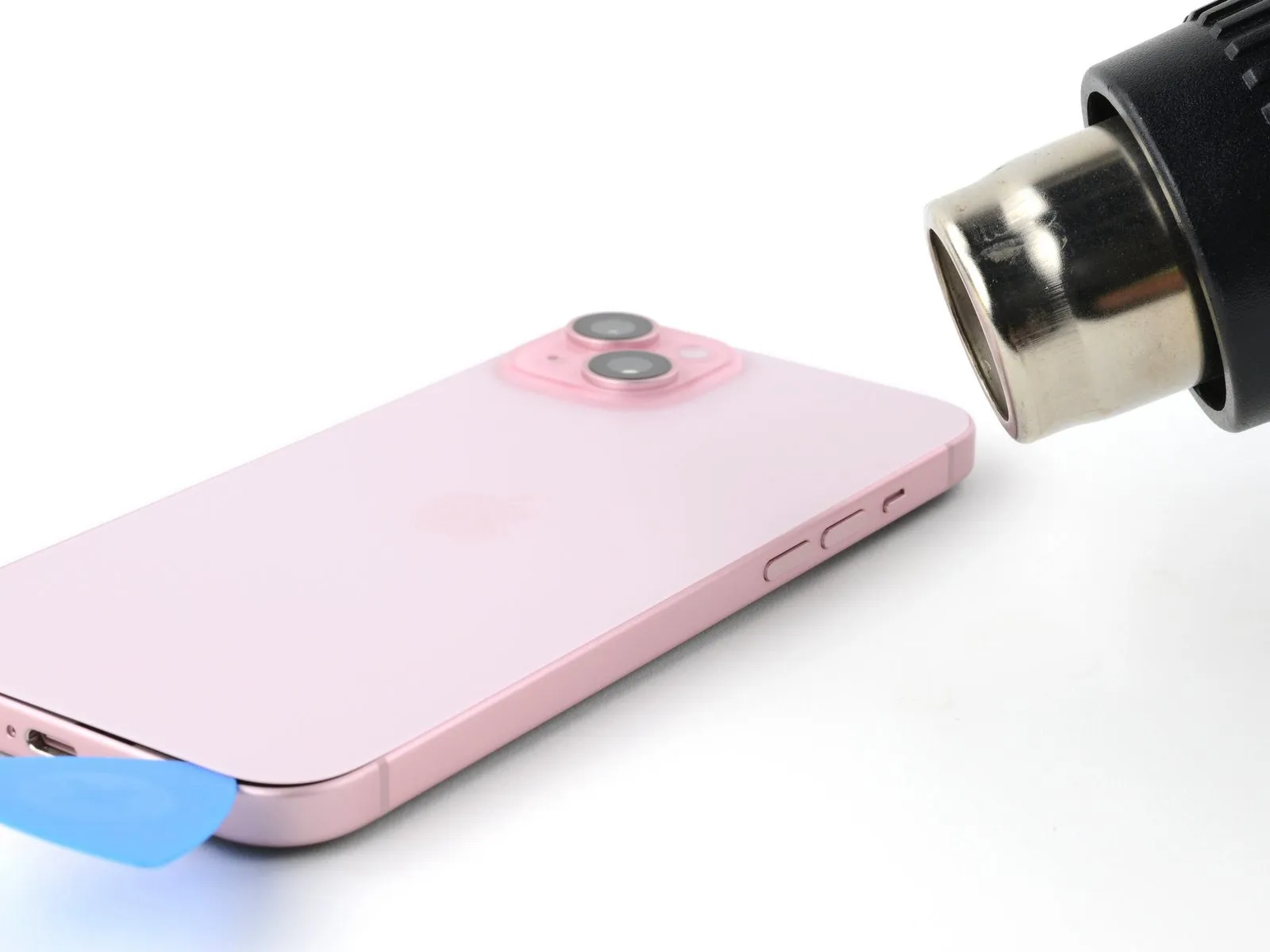
Heat the right edge of the back glass until it's hot to the touch.
Step 10 | Separate the bottom right corner adhesive
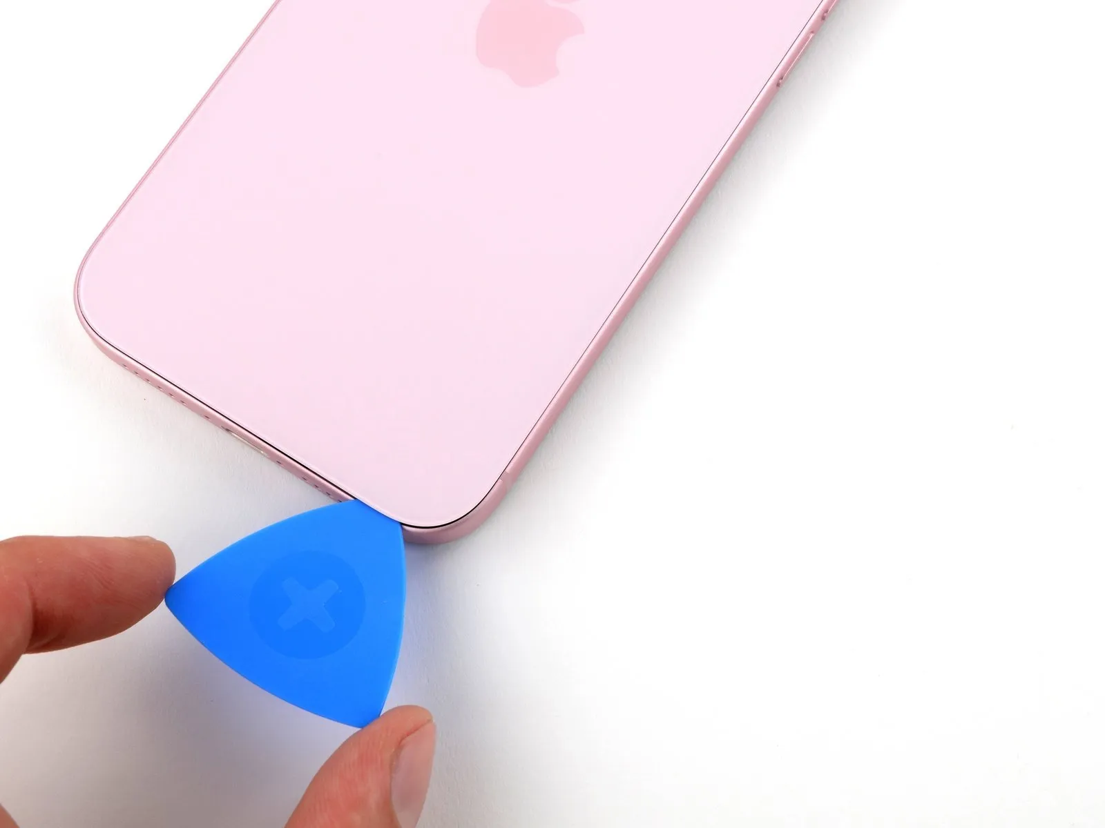

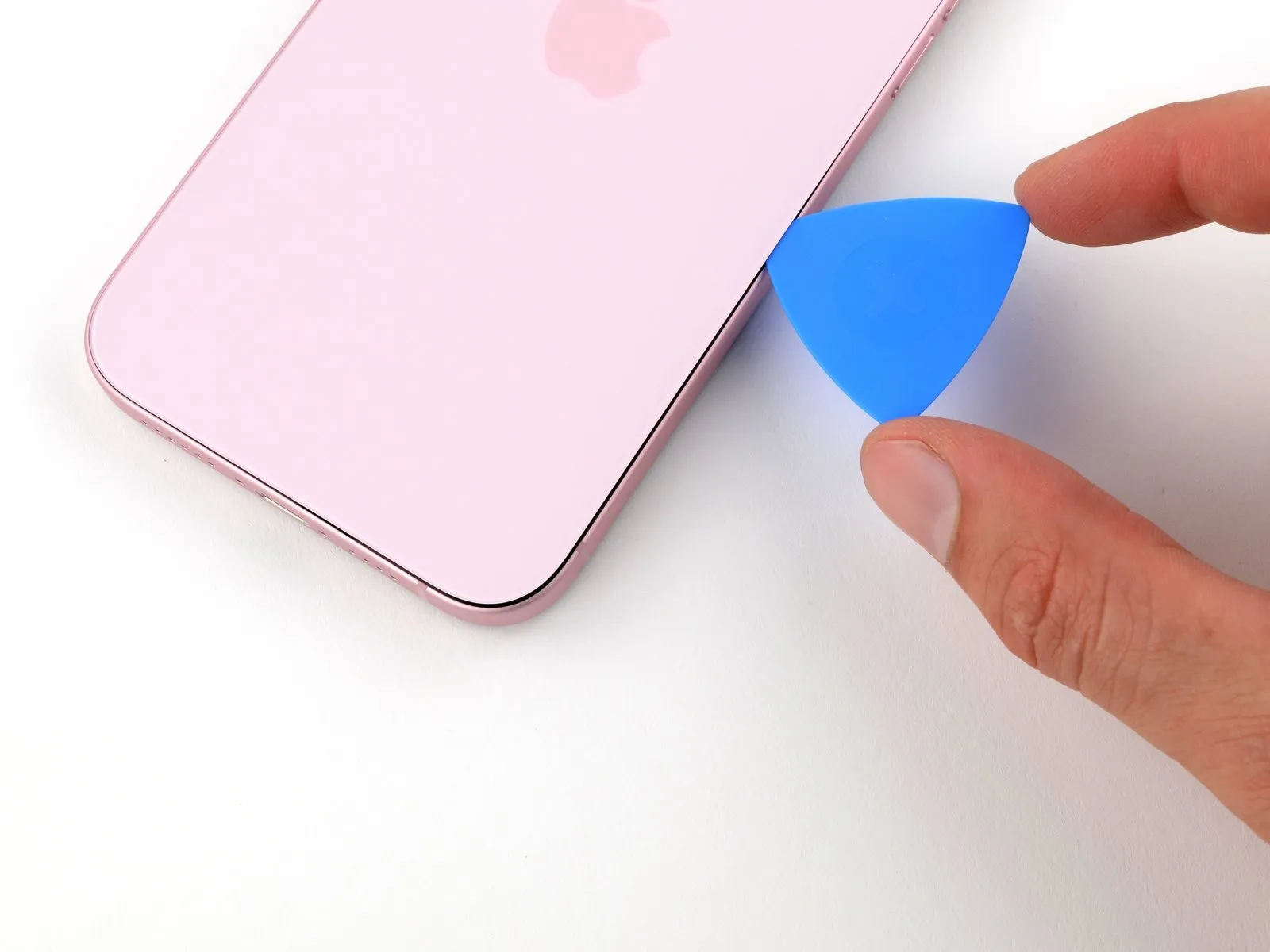
- Don't insert your pick deeper than 7 mm along the right edge.
- Rotate your pick around the bottom right corner and slide it halfway up the right edge or until you feel a hard stop at a clip securing the back glass.
- Don't slice near the volume buttons to avoid damaging the wireless charging cable.
- Leave this pick inserted to prevent the adhesive from re-sealing.
Step 11 | Heat the left edge
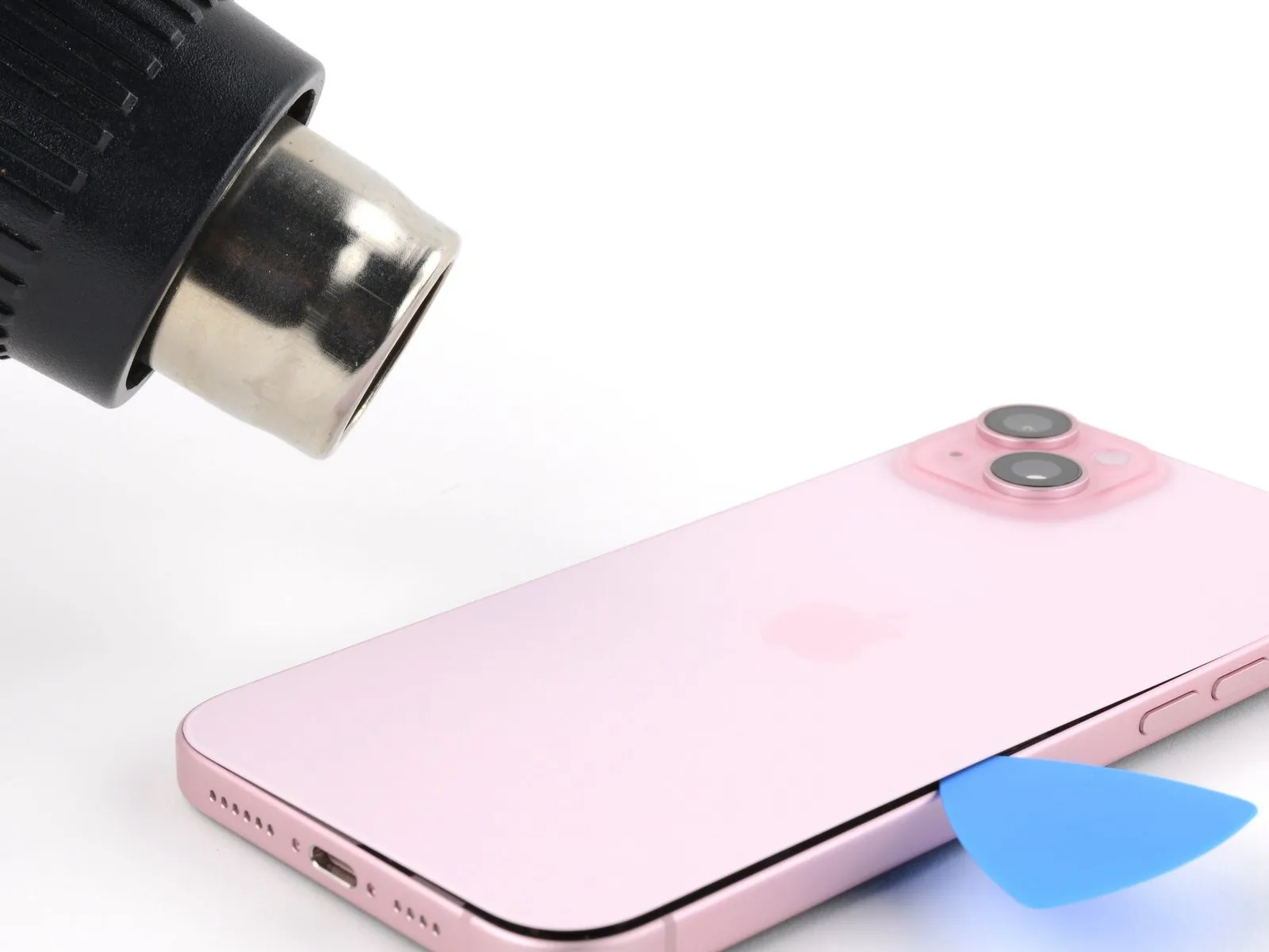
Heat the left edge of the back glass until it's hot to the touch.
Step 12 | Separate the left edge adhesive
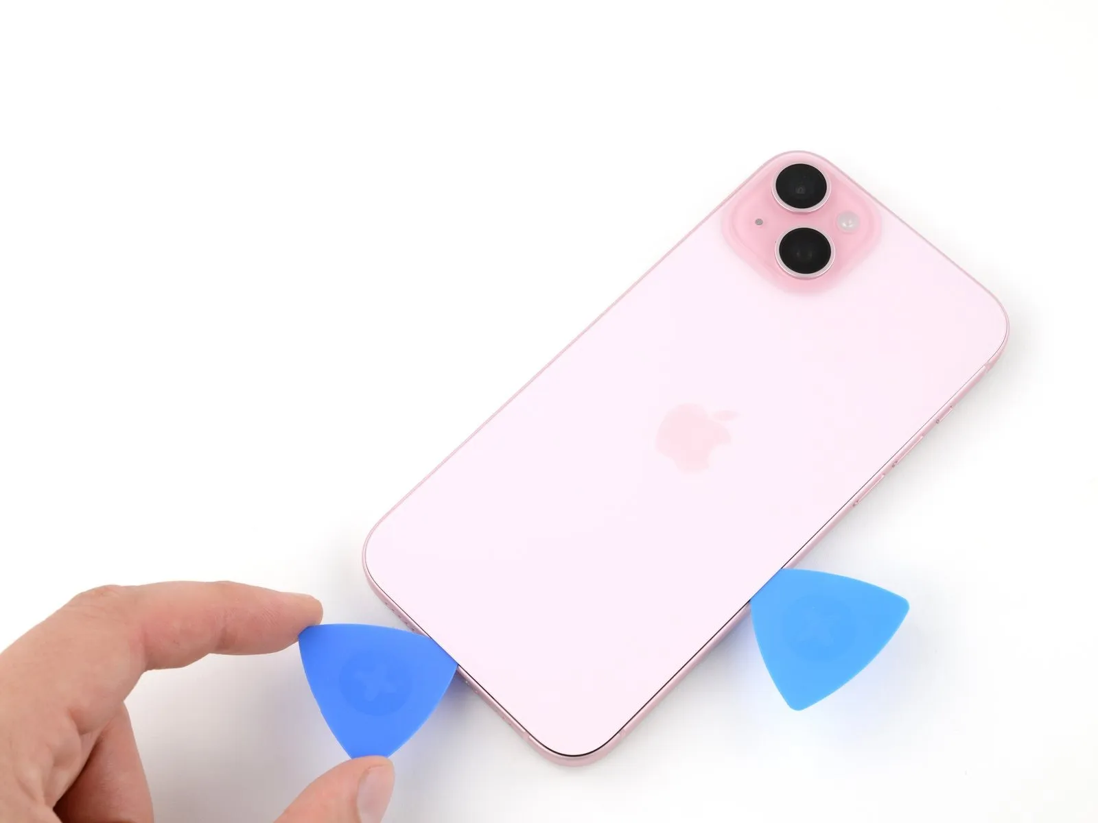
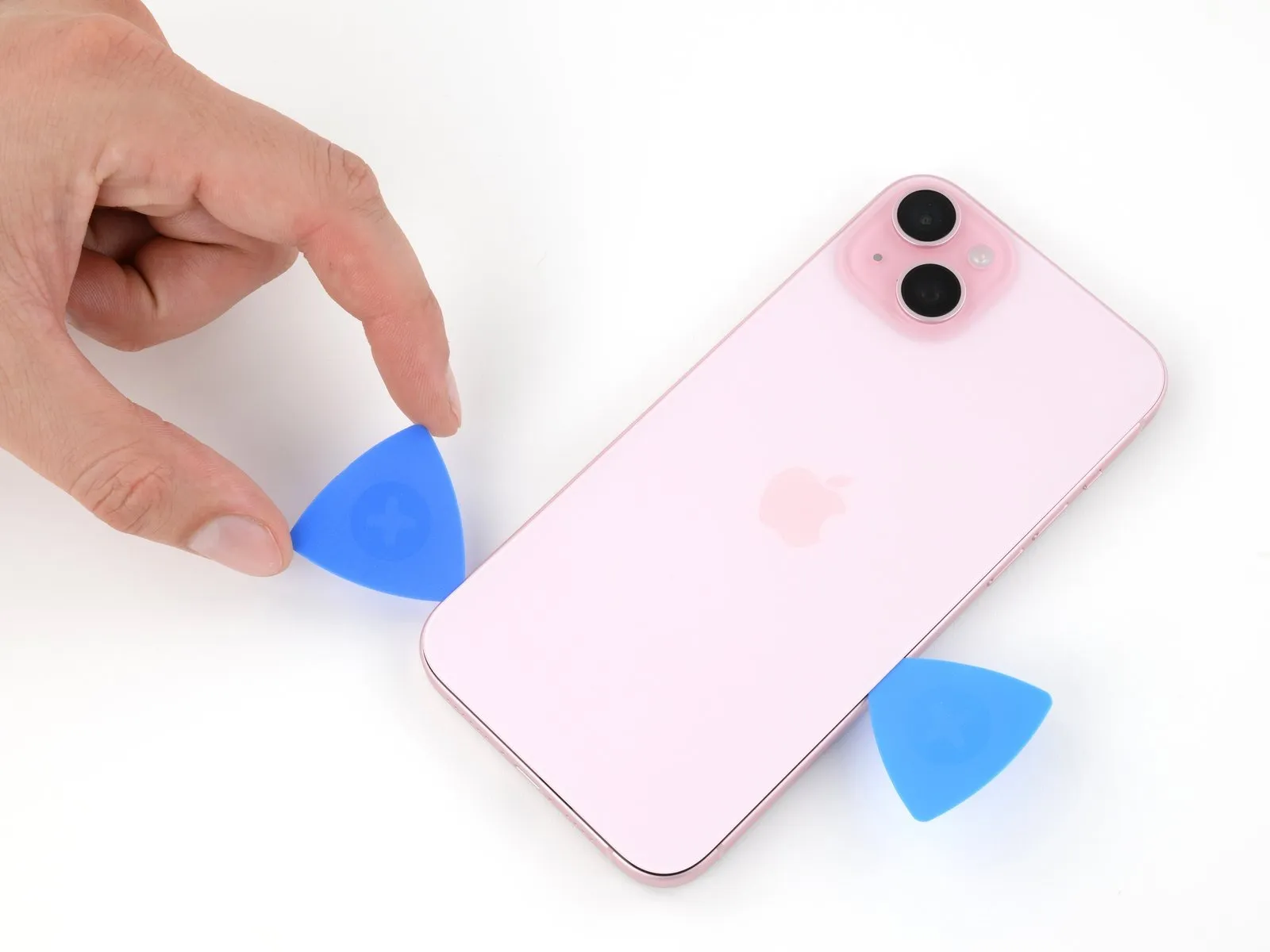
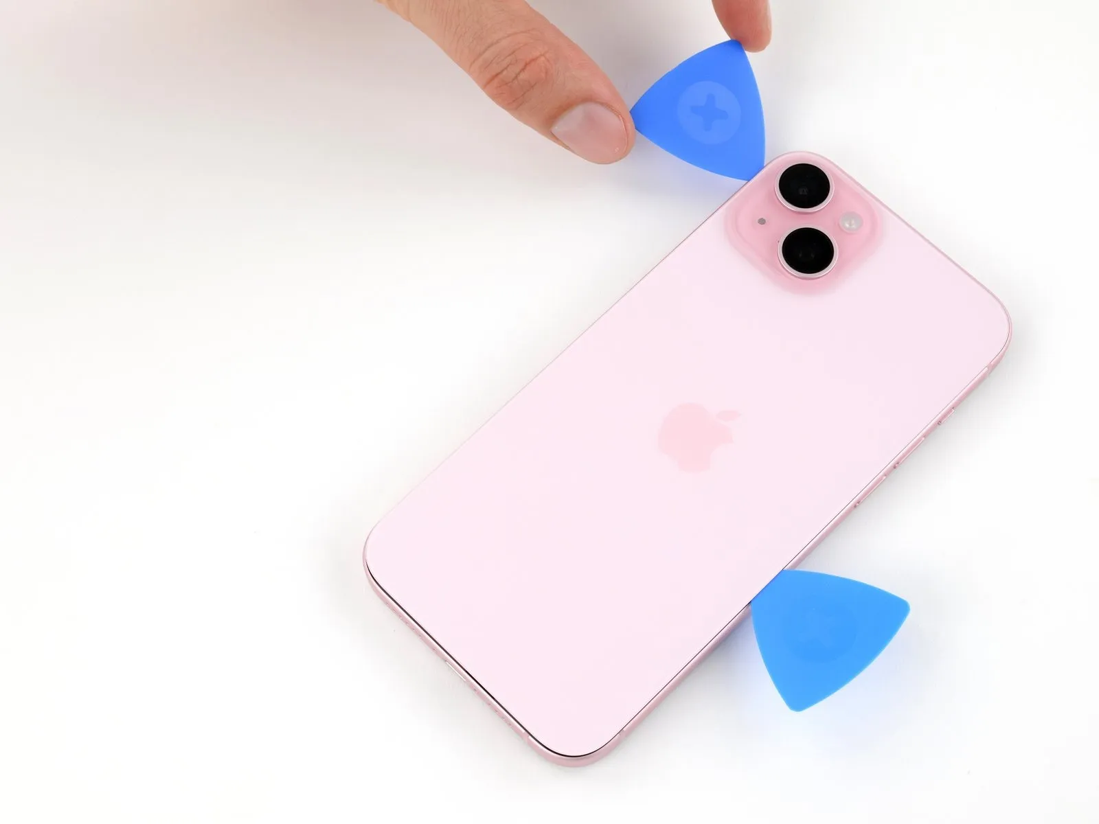
- Don't insert your pick deeper than 5 mm along the left edge.
- Insert a second opening pick at the bottom edge.
- Rotate the second pick around the bottom left corner.
- Slide this pick up to the top left corner to separate the adhesive.
- Leave this pick inserted to prevent the adhesive from resealing.
Step 13 | Heat the top edge

Heat the top edge of the back glass until it's hot to the touch.
Step 14 | Separate the top edge adhesive
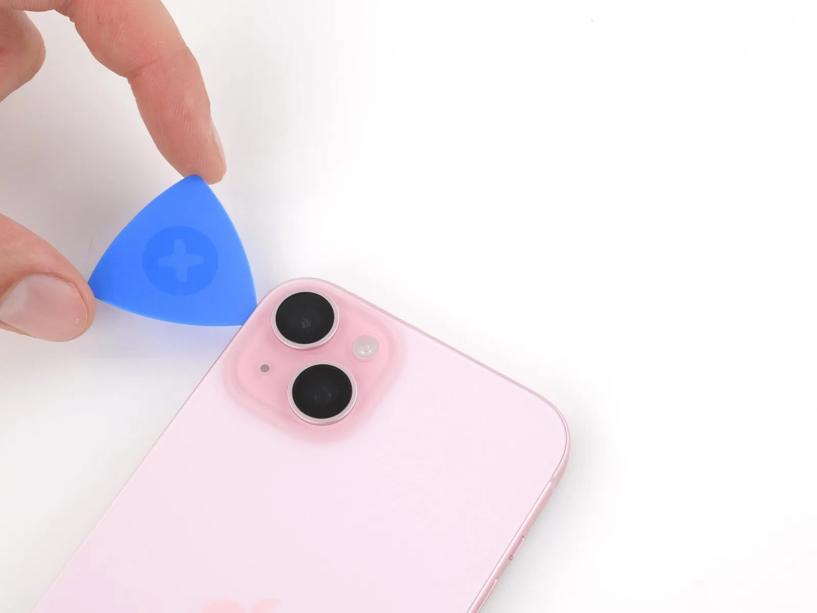
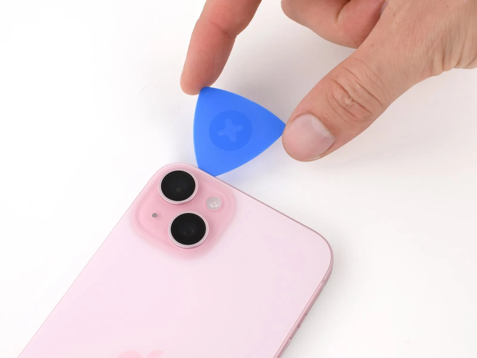
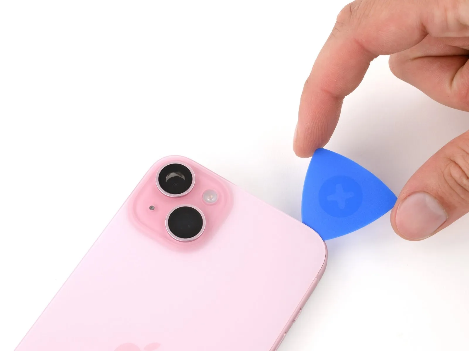
- Don't insert your pick deeper than 3 mm along the top edge.
- Rotate your second opening pick around the top left corner and slide it to the top right corner to separate the adhesive.
- You might hear and feel clicks as the top two clips release.
- Leave this pick in place to prevent the adhesive from resealing.
Step 15 | Heat the top right corner
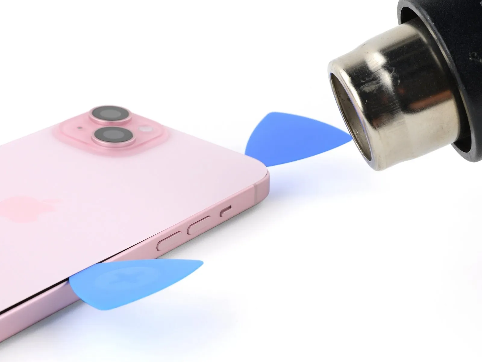
Heat the top right corner of the back glass until it's hot to the touch.
Step 16 | Separate the top right corner adhesive
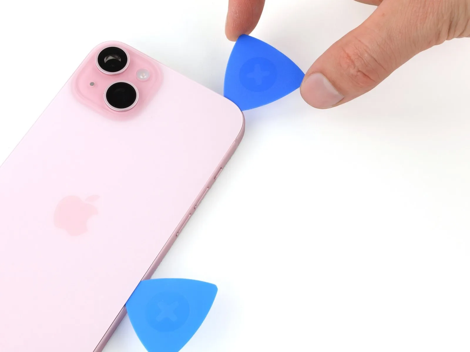

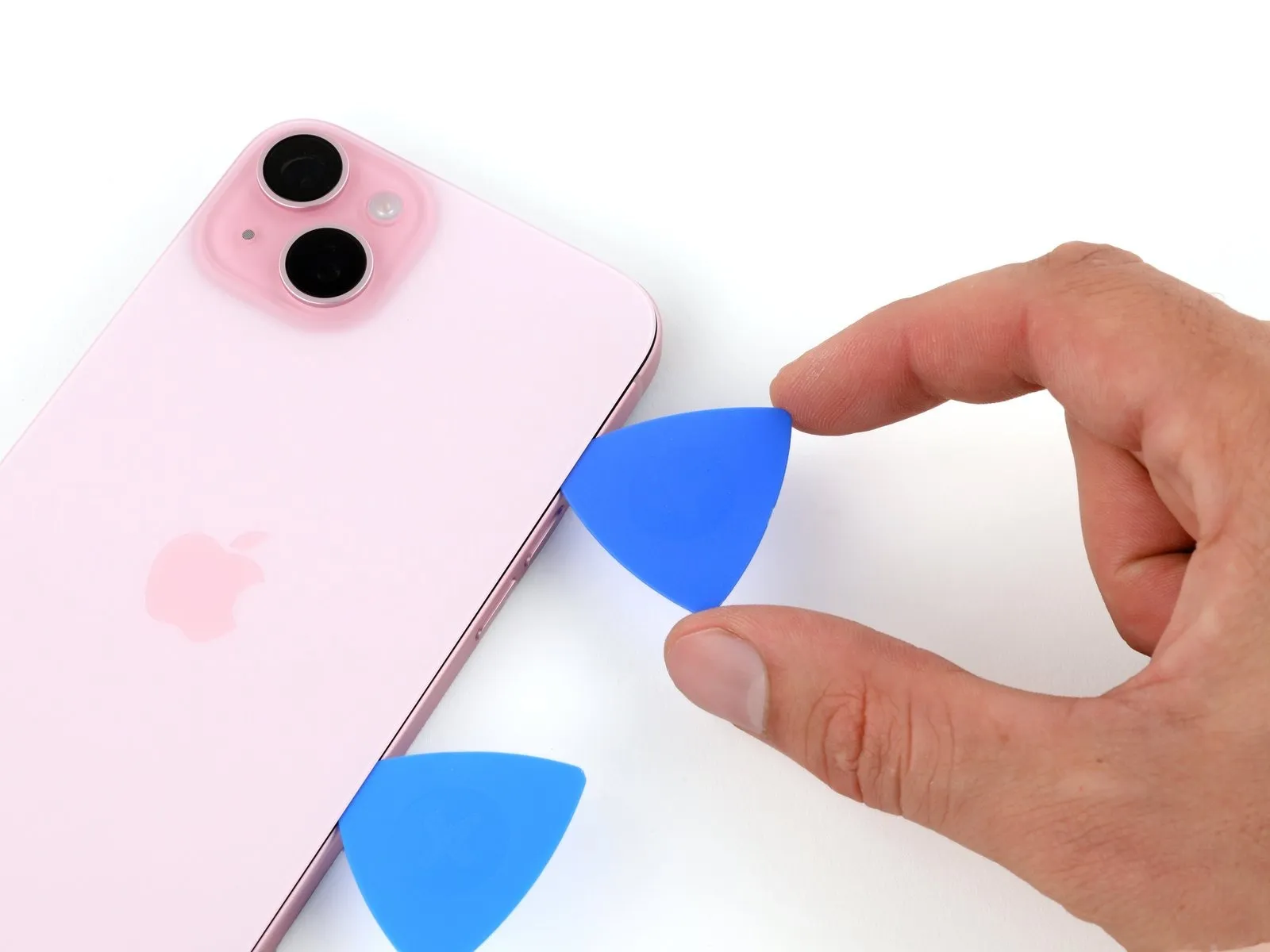
- Don't insert your pick deeper than 4 mm along the right edge.
- Rotate the second opening pick around the top right corner and slide it to the volume up button to separate the adhesive.
Step 17 | Swing open the back glass
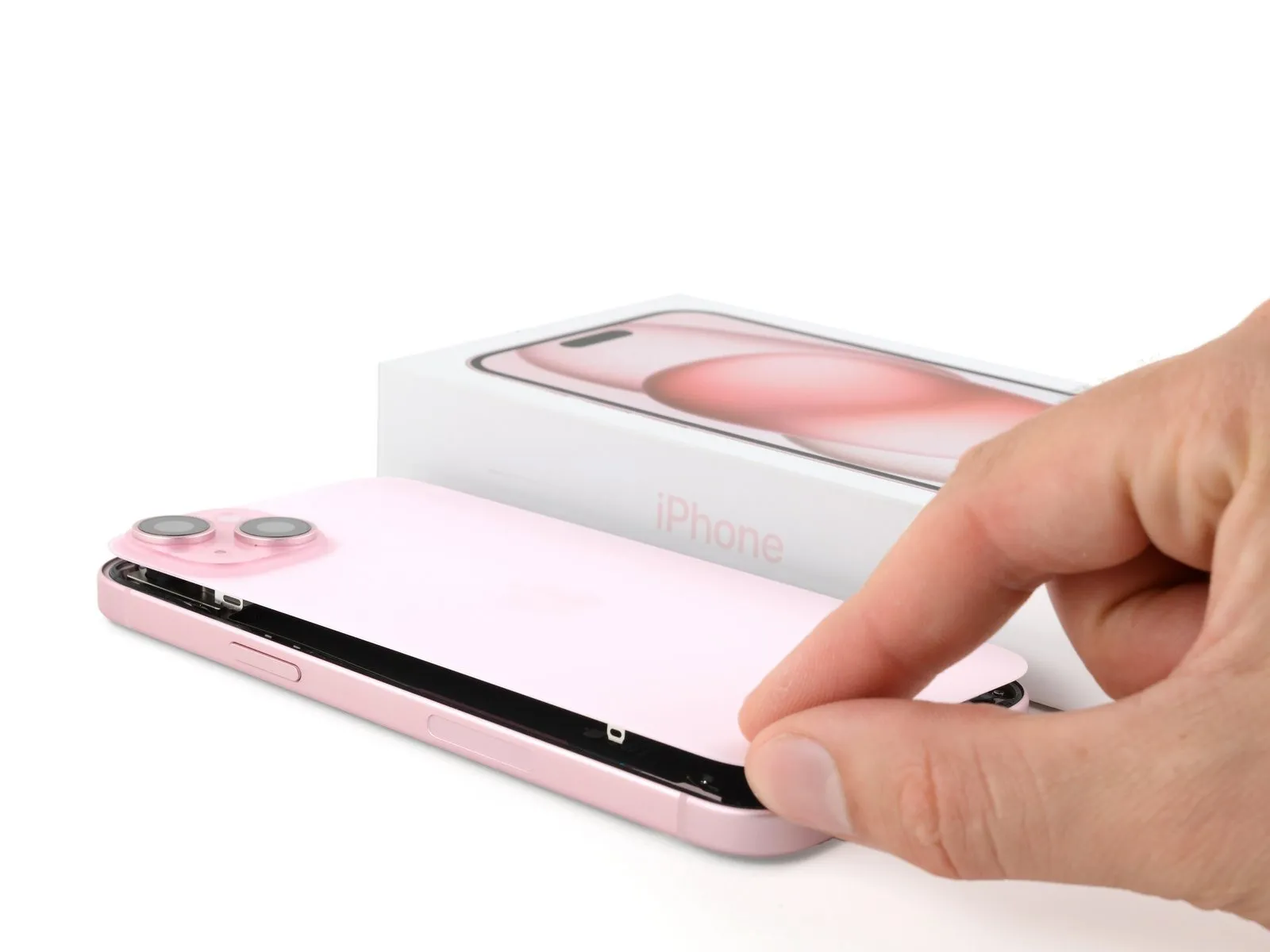
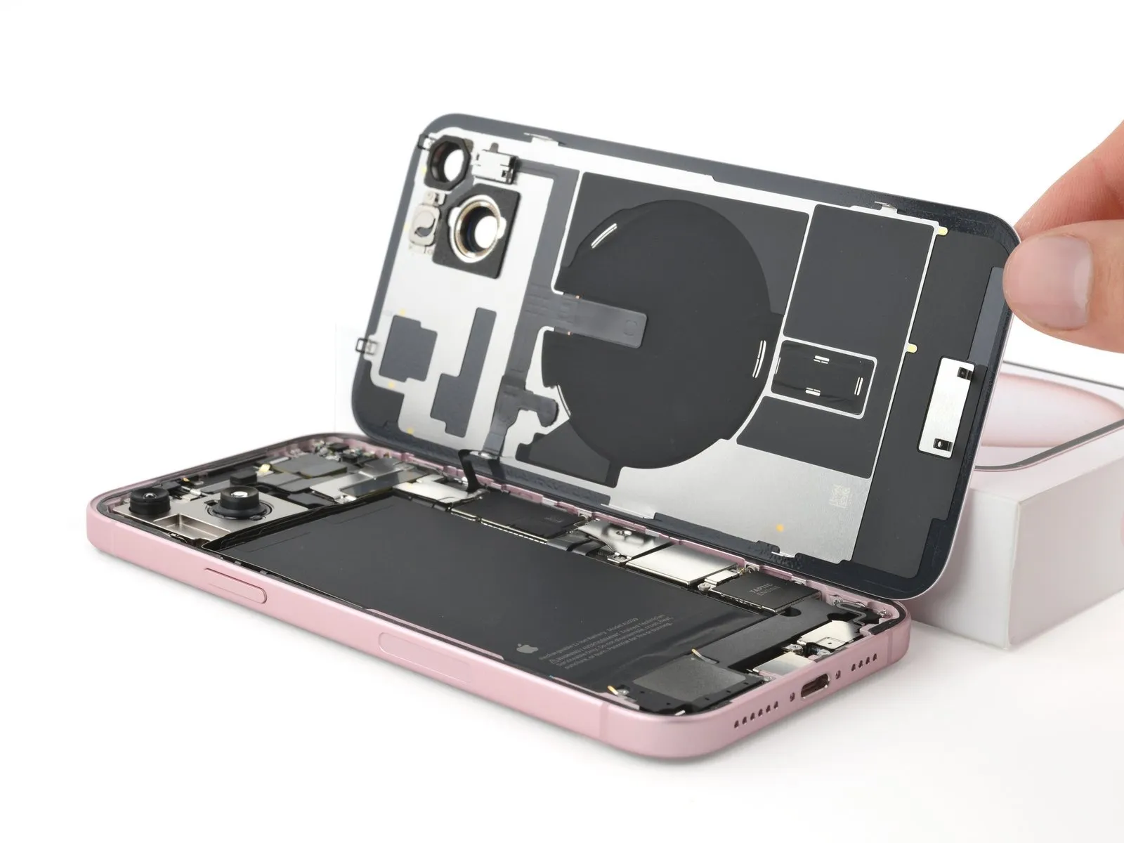
- Gently swing open the back glass to the right of the phone.
- If the back glass feels stuck, go back around the perimeter to check for missed sections of adhesive or stuck clips.
- Rest the back glass against a raised surface so it doesn't strain the cable.
Step 18 | Unfasten the lower connector cover
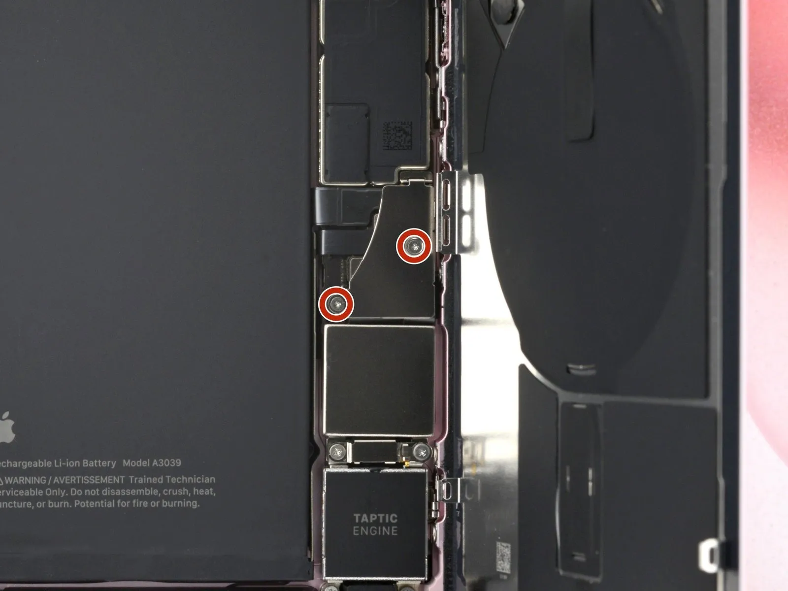

- Throughout this repair, keep track of each screw and make sure it goes back exactly where it came from.
- Use a tri-point Y000 driver to remove the two 1.3 mm-long screws securing the lower connector cover.
Step 19 | Remove the lower connector cover
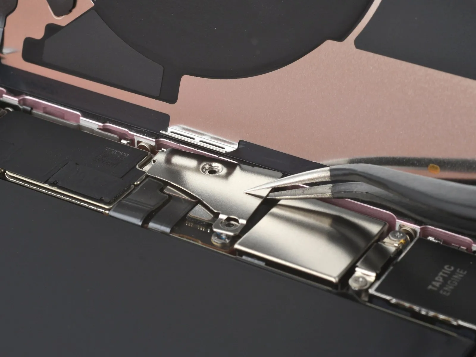
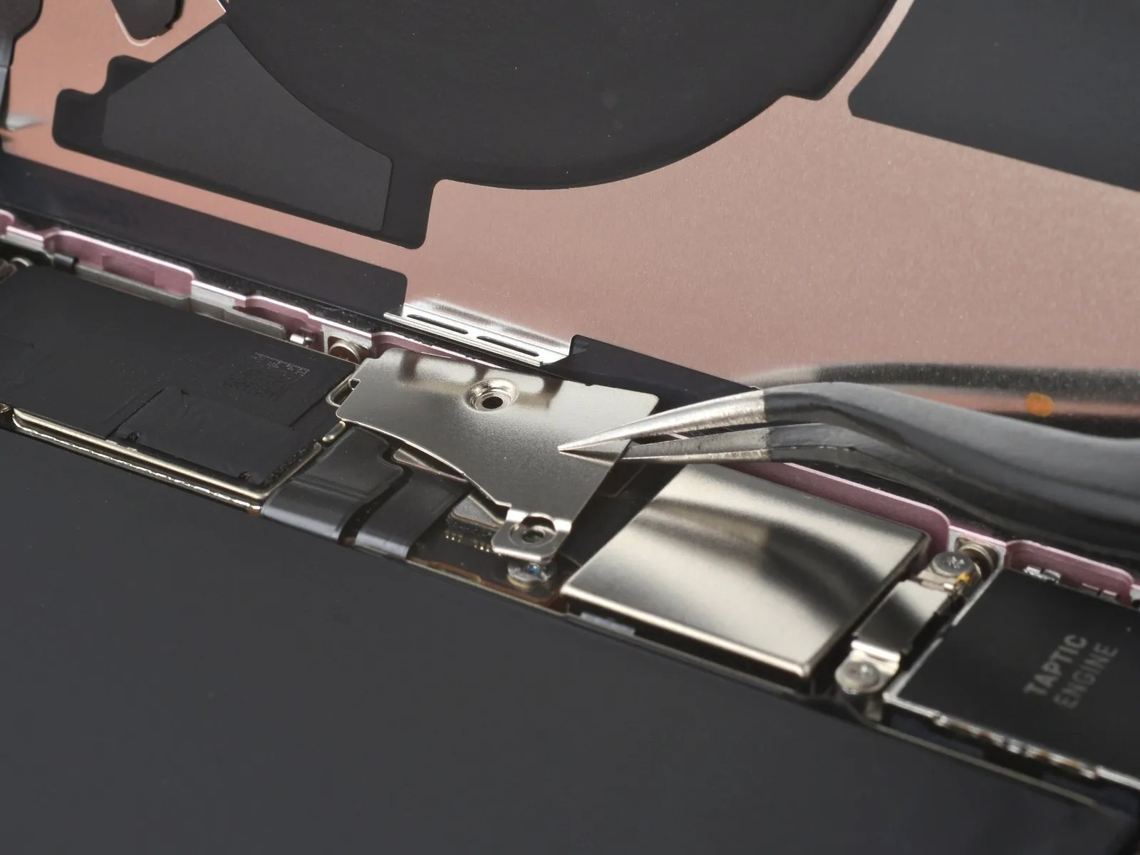
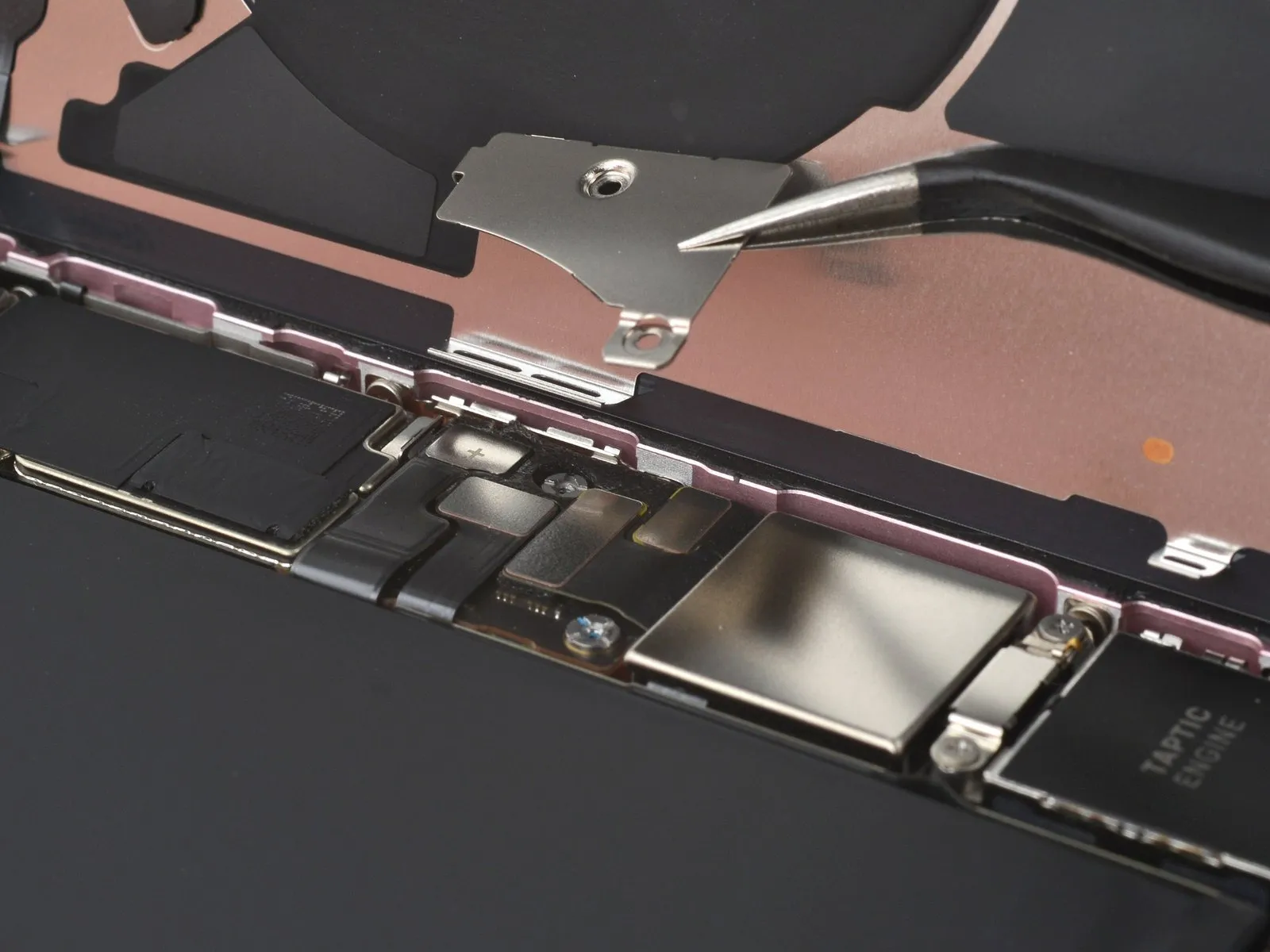
- Use tweezers to slide the cover toward the top of the phone to unlatch it from the logic board.
- Remove the cover.
Step 20
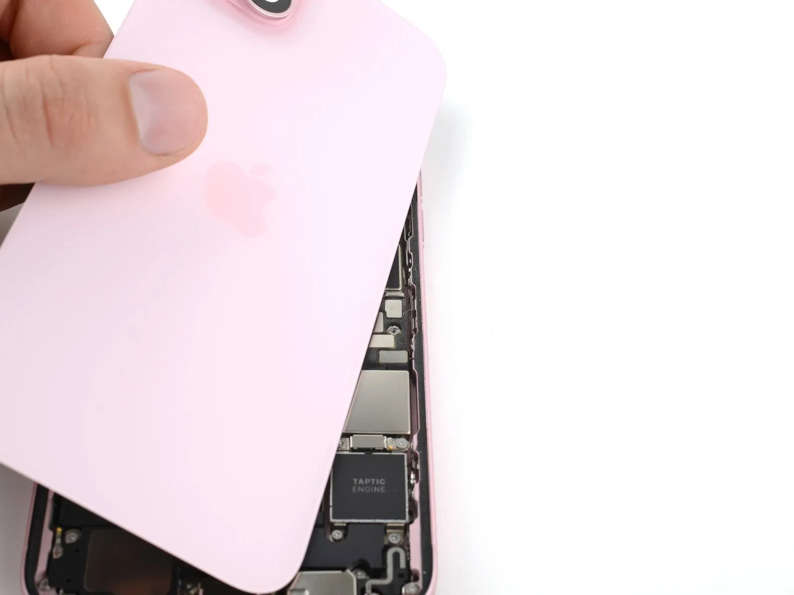
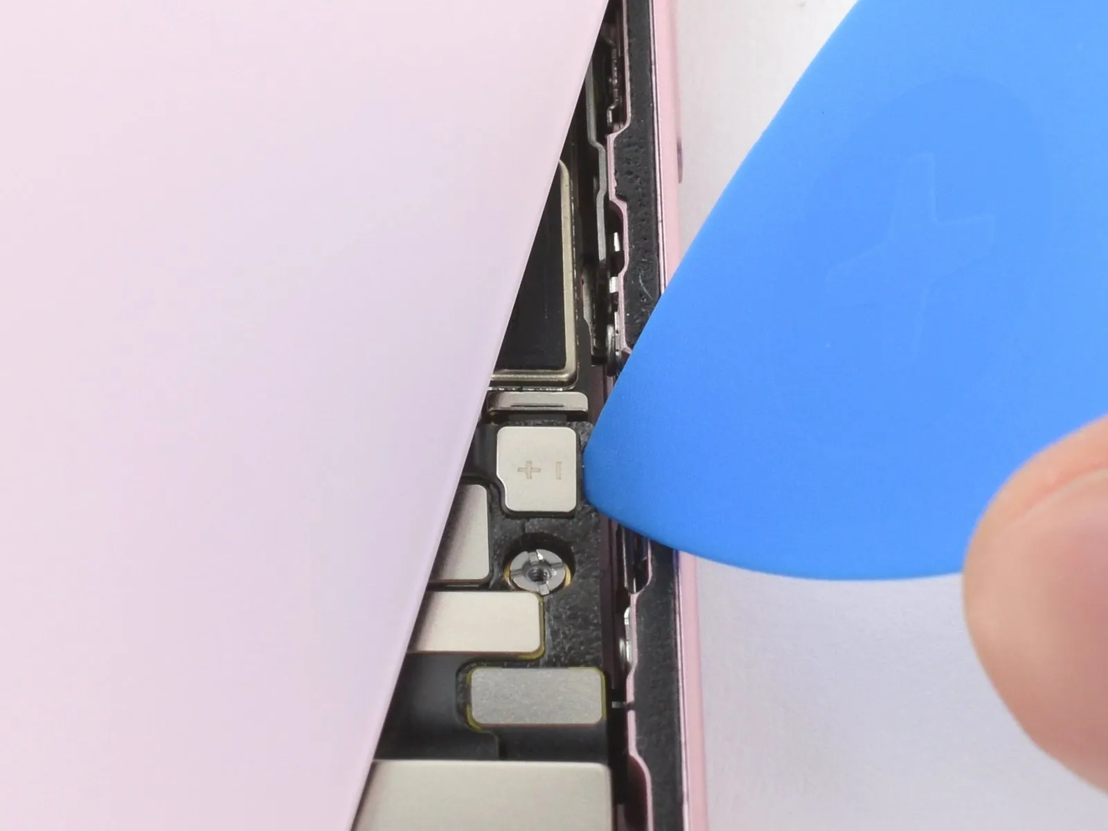
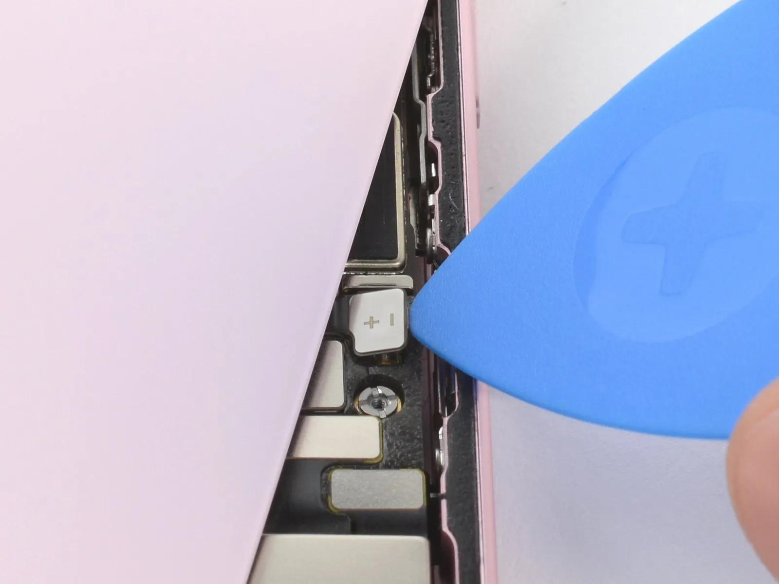
- Hold the back glass upright with one hand and rotate the bottom edge to the left to reveal the battery press connector just below the volume buttons.
- Use the tip of an opening pick to pry up and disconnect the battery press connector from the logic board.
- A plus and minus sign is printed on the head of this connector.
- To reconnect a press connector, align it over its socket and gently press down on one side until it clicks into place, then press down on the other side. Make sure it sits flat, as the insulating rubber around the sockets might prevent it from connecting fully.
Step 21 | Unfasten the Taptic Engine connector cover
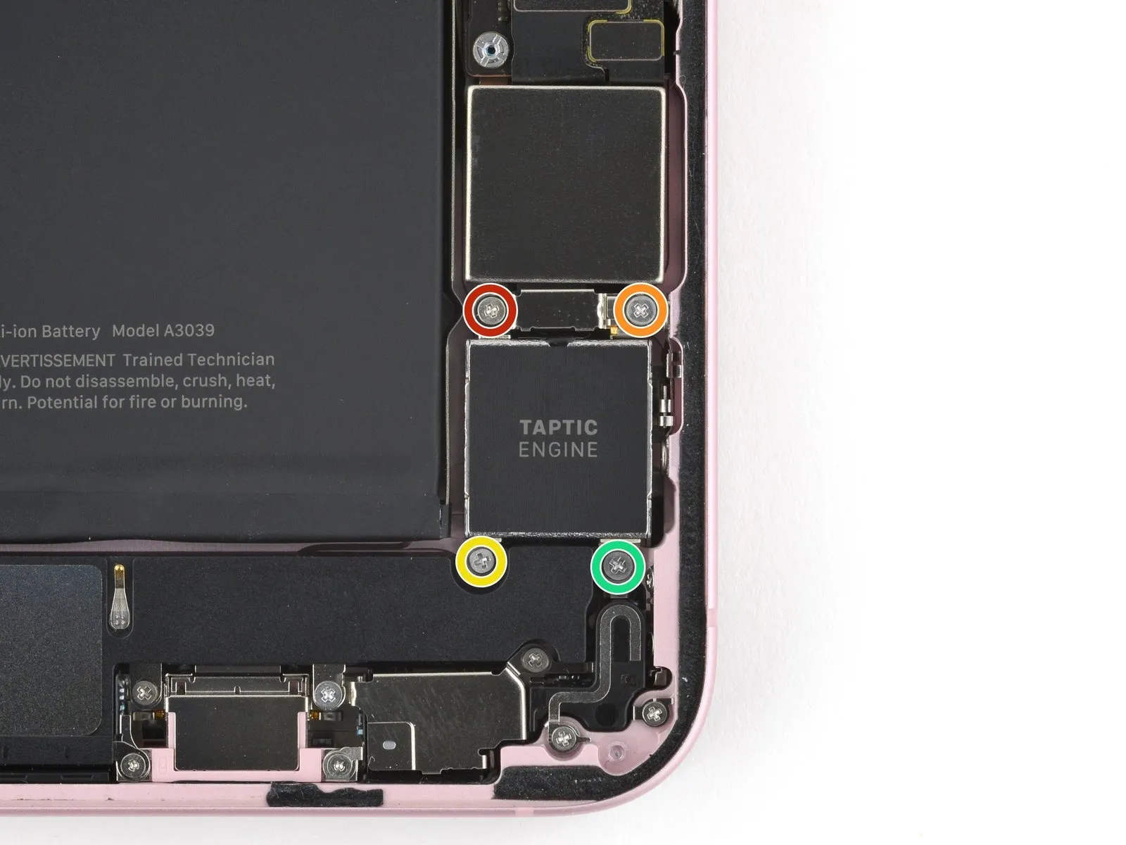
- Use your Phillips #000 driver to remove the four screws securing the Taptic Engine and its connector cover:
- One 1.4 mm-long screw
- One 1.9 mm-long screw (larger screw head)
- One 1.9 mm-long screw (smaller screw head)
- One 2.1 mm-long screw
Step 22 | Remove the cover


- Use tweezers to remove the Taptic Engine connector cover.
- During reassembly, orient the cover so that its gold spring contact is closest to the edge of the frame.
Step 23 | Disconnect the Taptic Engine


- Use the point of your spudger to pry up and disconnect the Taptic Engine press connector.
Step 24 | Unfasten the Taptic Engine

- Use a standoff driver to remove the 3.3 mm screw securing the top left of the Taptic Engine.
- If you don't have a standoff driver, you may use a thin flathead driver-but be careful not to strip the shallow notches in the screw heads.
Step 25 | Remove the Taptic Engine


Step 26 | Unfasten the loudspeaker

- Use your tri-point Y000 driver to remove the 1.3 mm screw securing a grounding contact and the loudspeaker.
- Use your Phillips #000 driver to remove the four screws securing the loudspeaker:
- Two 1.6 mm screws
- Two 2.0 mm screws
Step 27 | Remove the loudspeaker


Grab the loudspeaker and remove it.
Step 28 | Disconnect the microphone


Use the point of your spudger to pry up and disconnect the microphone press connector.
Step 29 | Unfasten the microphone

- Use your tri-point Y000 driver to remove the 1.3 mm screw securing a grounding contact and the microphone.
- Use your Phillips #000 driver to remove the two screws securing the right side of the microphone:
- One 1.9 mm screw
- One 1.3 mm screw
- Use your standoff driver to remove the 3.2 mm standoff screw securing the top left of the microphone.
Step 30 | Remove the microphone


Insert the flat end of a spudger under the top right screw mount of the microphone and pry up until you can grab it with your fingers.
Pull the microphone from the adhesive securing it to the frame and remove it.
During reassembly, you may replace the adhesive that secures the microphone with thin, double-sided tape, but make sure your new adhesive doesn't block the sound cutouts.