Fix iPhone 12 Pro Stuck on Apple Logo
Prior to commencing any repair work, disconnect the device entirely from all electrical power supplies to guarantee safety.
- The following implements are necessary to complete the repair process:A Phillips head screwdriver is needed for disassembly and reassembly.
Consult the device's user documentation for precise specifications related to your particular model and supplementary safety guidelines.
Step 1 | How to Fix iPhone 12 Pro Stuck on Apple Logo
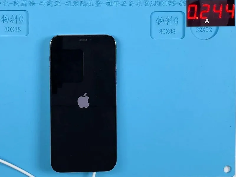
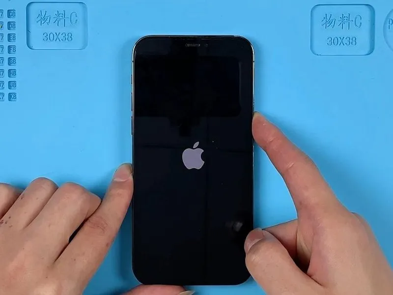
- Previously functional, the device now halts during the boot process, displaying the Apple logo, following a charging cycle.
- Isolate all flex cables, retaining only the power cable connection; subsequently, reconnect the display and power cable assembly; continued display of the Apple logo confirms a motherboard failure, as evidenced by a boot current interruption approximately 240 milliamperes in magnitude.
Step 2
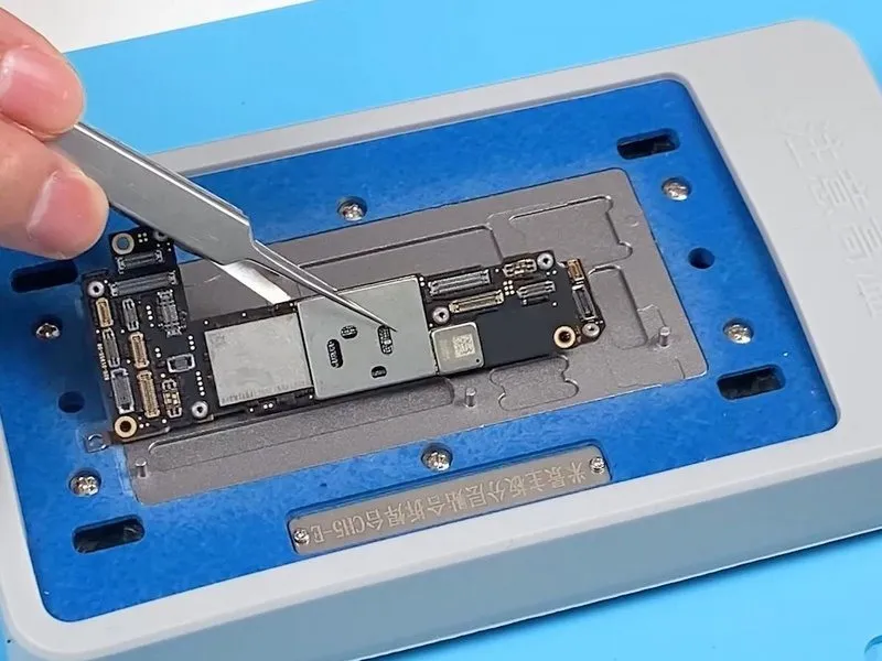
- The charging current plateaus around 240 milliamperes, and the device displays a static Apple logo following a charging attempt, indicating a likely issue within the USB charging circuit; the USB integrated circuit resides at the initial stage of this circuit.
- To address the suspected problem, proceed with replacing the USB IC component.
- Employ a 200°C heating platform to warm the motherboard, supplementing with a 330°C hot air gun applied vertically; utilize a pry bar to gently separate the logic board while applying heat, then extract the component with tweezers once it releases.
Step 3
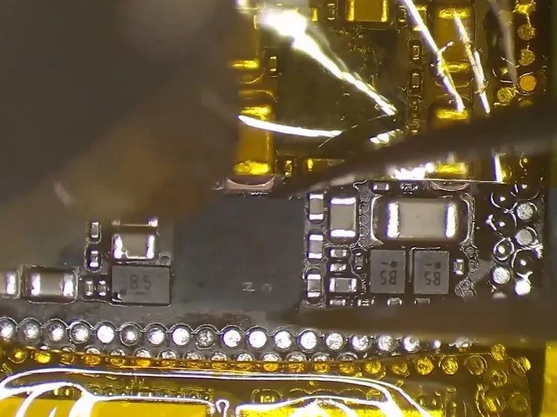
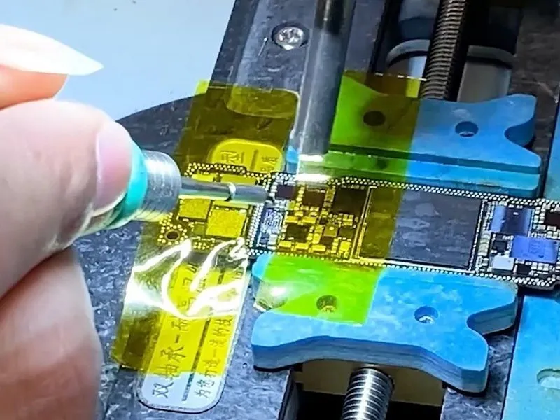
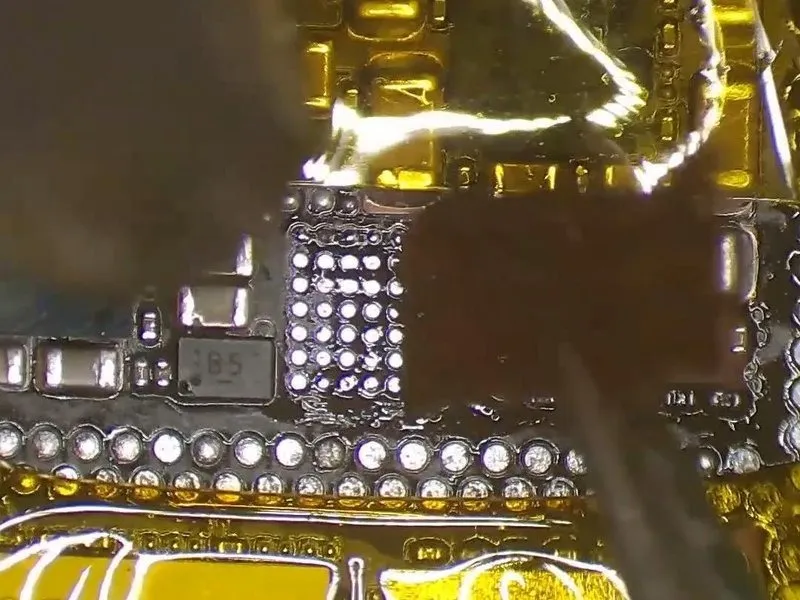
- Secure the main circuit board within the designated retention fixture.
- Introduce Paste Flux to the USB integrated circuit; then, utilize a hot air rework station, maintaining a temperature of 340 degrees Celsius and an airflow rate of 3.0, to heat the component, gently manipulating it with tweezers during the heating process to facilitate removal if separation occurs.
- Employ a soldering iron at 365 degrees Celsius, coupled with a hot air rework station at 340 degrees Celsius, to eliminate excess solder from the bonding pad, subsequently cleaning the area with solder wick to ensure complete removal.
Step 4
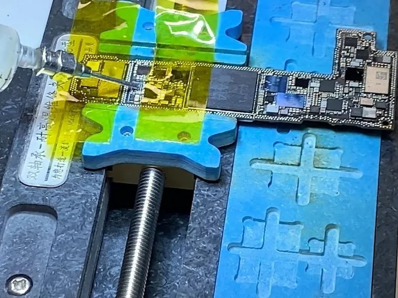
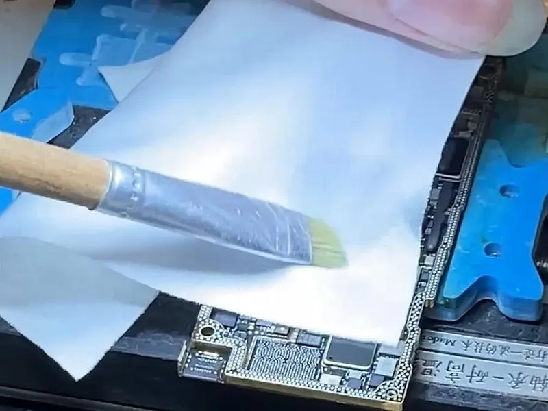
- To facilitate a secure solder connection, apply a thin layer of Paste Flux to the designated bonding pad area.
- Carefully position the replacement USB IC, ensuring precise alignment with its corresponding location.
- Utilize a Hot Air Gun, maintaining a temperature of 340 degrees Celsius, to reflow solder and secure the USB IC; subsequently, remove excess solder from the bonding pad using a soldering iron set to 365 degrees Celsius, combined with solder wick, and repeat this cleaning process on the signal board's bonding pad.
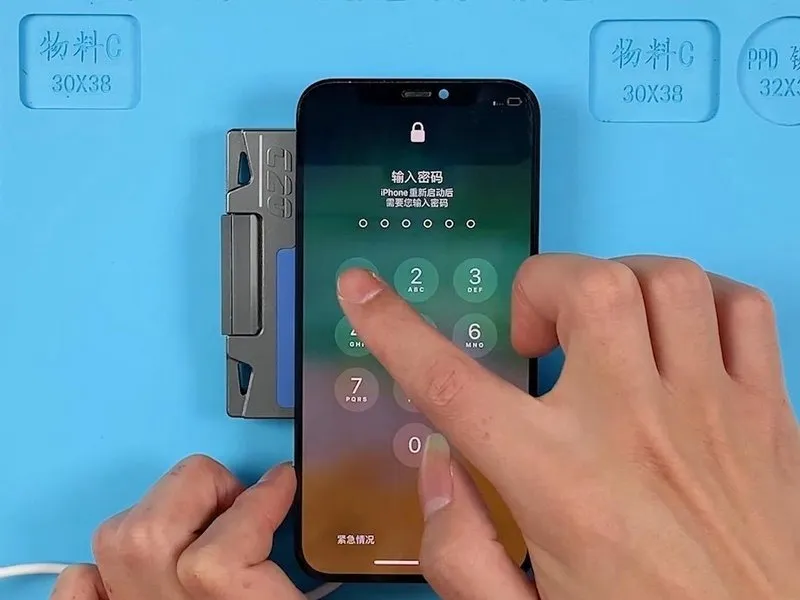
- Following the soldering procedure, mount the motherboard within the Testing Fixture, establish connections for the power cable and display screen, initiate the boot sequence using tweezers, and verify successful device activation.
Step 5
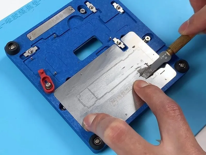
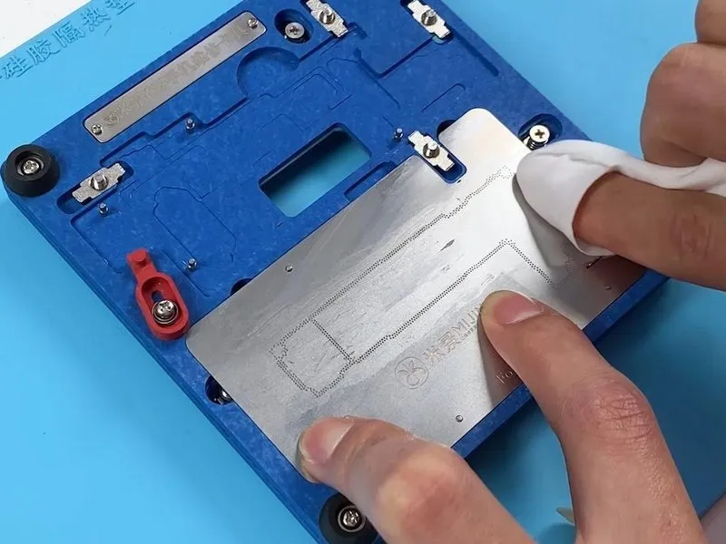
- Secure the signal board to the designated Reballing Platform.Position the reballing stencil precisely over the target area.Distribute a uniform layer of Solder Paste across the stencil’s openings.
- Carefully eliminate any surplus Solder Paste and then detach the reballing stencil.
- Ensure the Solder Paste application is consistent and complete.The Reballing Platform provides a stable base for the component attachment.Proper stencil placement is critical for accurate solder ball formation.
- Residual Solder Paste can cause shorts, so thorough cleaning is essential.
Step 6
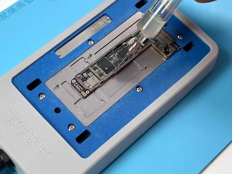
- Position the signal board onto the designated 160°C heating platform for thermal processing.Allow the formation of solder balls on the signal board's surface, then permit it to return to ambient temperature.Dispense a quantity of Paste Flux onto the bonding pad area to facilitate the reflow process.
Carefully position the logic board in precise alignment with the signal board.Resume heating the assembly to re-establish the connection between the motherboard and signal board.After approximately two minutes of continued heating, carefully remove the motherboard from the platform.
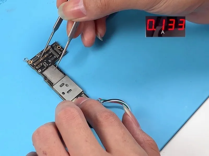
Allow the motherboard to cool down to a safe temperature before applying power. - Utilize tweezers to initiate the boot sequence; a momentary surge in boot current is a typical occurrence.
Securely install the motherboard within the device's housing.
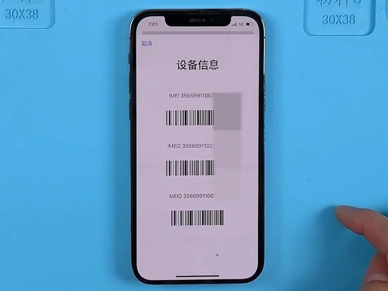
The device should now power on, displaying the IMEI number, indicating successful fault remediation. - Successful completion of this procedure demonstrates the resolution of the identified issue.
Ensure proper ventilation and avoid prolonged exposure to heat during the heating and cooling phases.